

Dell OptiPlex 755 User Manual [en, de, es, fr, it]

Dell™ OptiPlex™ 755
Quick Reference Guide
Models DCTR, DCNE, DCSM, and DCCY
www.dell.com | support.dell.com

Notes, Notices, and Cautions
NOTE: A NOTE indicates important information that helps you make better use of
your computer.
NOTICE: A NOTICE indicates either potential damage to hardware or loss of data
and tells you how to avoid the problem.
CAUTION: A CAUTION indicates a potential for property damage, personal injury,
or death.
____________________
Information in this document is subject to change without notice.
© 2007 Dell Inc. All rights reserved.
Reproduction in any manner whatsoever without the written permission of Dell Inc. is strictly
forbidden.
Trademarks used in this text: Dell, the DELL logo, OptiPlex, Inspiron, Dimension, Latitude, Dell
Precision, DellNet, TravelLite, OpenManage, PowerVault, Axim, PowerEdge, PowerConnect,
PowerApp, and StrikeZone are trademarks of Dell Inc.; Intel, Pentium, SpeedStep, and Celeron are
registered trademarks and Core and vPro are trademarks of Intel Corporation in the U.S and other
countries; Microsoft, MS-DOS, W indows, Windows V ista, and the W indows Vista Start b utton are either
registered trademarks or trademarks of Microsoft Corporation in the United States and/or other
countries; IBM is a registered trademark of International Business Machines Corporation; Bluetooth
is a trademark owned by Bluetooth SIG, Inc. and is used by Dell Inc. under license. ENERGY STAR
is a registered trademark of the U.S. Environmental Protection Agency . As an ENERGY ST AR partner,
Dell Inc. has determined that this product meets the ENERGY ST AR guidelines for energy ef ficiency.
Other trademarks and trade names may be used in this document to refer to either the entities claiming
the marks and names or their products. Dell Inc. disclaims any proprietary interest in trademarks and
trade names other than its own.
Models: DCTR, DCNE, DCSM, and DCCY
July 2007 FN392 Rev. A00

Contents
Finding Information . . . . . . . . . . . . . . . . . . . . 5
Setting Up Your Computer
Set Up Your Keyboard and Mouse
Set Up Your Monitor
Power Connections
. . . . . . . . . . . . . . . . 10
. . . . . . . . . 11
. . . . . . . . . . . . . . . . 12
. . . . . . . . . . . . . . . . 12
Before You Begin . . . . . . . . . . . . . . . . . . . . 13
Recommended Tools
Turning Off Your Computer
Before Working Inside Your Computer
Mini Tower Computer
System Views
Removing the Computer Cover
Inside Your Computer
System Board Components
Jumper Settings
Desktop Computer
System Views
Removing the Computer Cover
Inside Your Computer
System Board Components
Jumper Settings
. . . . . . . . . . . . . . . . 13
. . . . . . . . . . . . . 13
. . . . . . . 14
. . . . . . . . . . . . . . . . . . 16
. . . . . . . . . . . . . . . . . . . . 16
. . . . . . . . . . . 22
. . . . . . . . . . . . . . . 24
. . . . . . . . . . . . 25
. . . . . . . . . . . . . . . . . . 26
. . . . . . . . . . . . . . . . . . . . 27
. . . . . . . . . . . . . . . . . . . . 27
. . . . . . . . . . . 32
. . . . . . . . . . . . . . . 33
. . . . . . . . . . . . 35
. . . . . . . . . . . . . . . . . . 36
Small Form Factor Computer
System Views
. . . . . . . . . . . . . . . . . . . . 37
Removing the Computer Cover
. . . . . . . . . . . . . . 37
. . . . . . . . . . . 43
Contents 3

Inside Your Computer . . . . . . . . . . . . . . . . 44
System Board Components
Jumper Settings
. . . . . . . . . . . . . . . . . . 47
. . . . . . . . . . . . . 46
Ultra Small Form Factor Computer
System Views
. . . . . . . . . . . . . . . . . . . . 48
Removing the Computer Cover
Inside Your Computer
Cable Cover (Optional)
System Board Components
Jumper Settings
Solving Problems
Dell Diagnostics
System Lights
Diagnostic Lights
Beep Codes
. . . . . . . . . . . . . . . . . . . . . 70
. . . . . . . . . . . . . . . . 56
. . . . . . . . . . . . . . . 57
. . . . . . . . . . . . . . . 59
. . . . . . . . . . . . . . . . . . 60
. . . . . . . . . . . . . . . . . . . . 61
. . . . . . . . . . . . . . . . . . 61
. . . . . . . . . . . . . . . . . . . . 65
. . . . . . . . . . . . . . . . . . 66
Resolving Software and Hardware
Incompatibilities
. . . . . . . . . . . . . . . . . . 72
Restoring Your Operating System
Using Microsoft
Windows System Restore . . . . 73
Using Dell™ PC Restore and Dell Factory
Image Restore
. . . . . . . . . . . . . . . . . . . 75
Using the Drivers and Utilities Media
Reinstalling Drivers and Utilities
. . . . . . . . . . . 48
. . . . . . . . . . . 55
. . . . . . . . . 73
. . . . . . . 78
. . . . . . . . . . 79
Index . . . . . . . . . . . . . . . . . . . . . . . . . . . . . . . 83
4 Contents
Finding Information
NOTE: Some features or media may be optional and may not ship with your
computer. Some features or media may not be available in certain countries.
NOTE: Additional information may ship with your computer.
What Are You Looking For? Find It Here
• A diagnostic program for my computer
• Drivers for my computer
• Desktop System Software (DSS)
Drivers and Utilities Media
NOTE: The Drivers and Utilities media may
be optional and may not ship with your
computer.
Documentation and drivers are already
installed on your computer. You can use
the media to reinstall drivers (see
"Reinstalling Drivers and Utilities" on
page 79), to run the Dell Diagnostics (see
"Dell Diagnostics" on page 61).
Readme files may be included on your
media to provide last-minute updates
about technical changes to your computer
or advanced technical-reference material
for technicians or experienced users.
NOTE: Drivers and documentation updates
can be found at support.dell.com.
Quick Reference Guide 5
What Are You Looking For? Find It Here
• How to set up my computer
• How to run the Dell Diagnostics
• Error codes and diagnostic lights
• Tools and utilities
• How to set up a printer
• How to troubleshoot and solve problems
• How to remove and install parts
Owner’s Manual
NOTE: This document may be optional and
may not ship with your computer.
NOTE: This document is available as a PDF
at support.dell.com.
• Warranty information
• Terms and Conditions (U.S. only)
• Safety instructions
• Regulatory information
• Ergonomics information
• End User License Agreement
Dell™ Product Information Guide
• How to remove and replace parts
• Specifications
• How to configure system settings
• How to troubleshoot and solve problems
6 Quick Reference Guide
Dell™ OptiPlex™ User’s Guide
Microsoft Windows Help and Support
Center
1
Click
Start
or
→
Help and
→
Support
Guides
2
Click the
computer.
Dell User and System
→
System Guides
User’s Guide
for your
.
What Are You Looking For? Find It Here
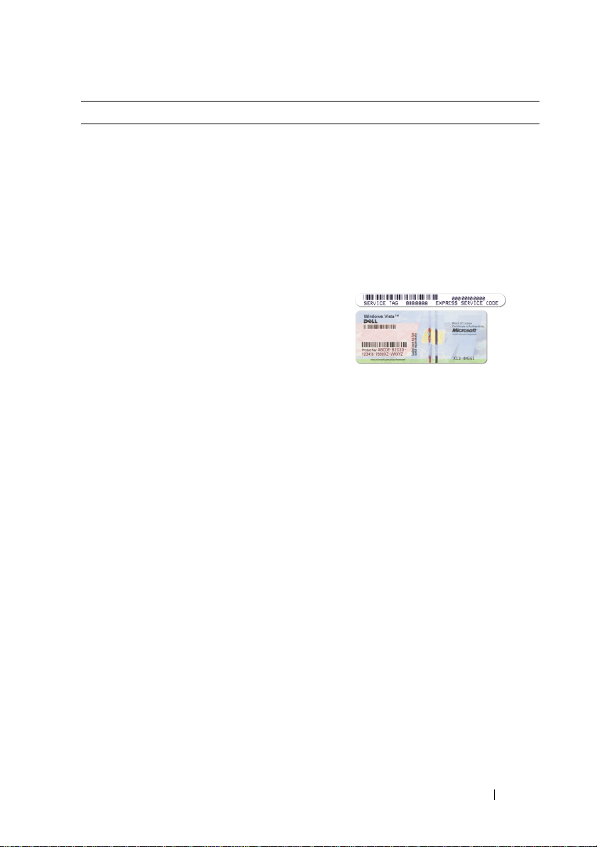
• Service Tag and Express Service Code
• Microsoft Windows License Label
Service Tag and Microsoft® Windows®
License
These labels are located on your
computer.
• Use the Service Tag to identify your
computer when you use
support.dell.com
• Enter the Express Service Code to direct
your call when contacting support.
NOTE: As an increased security measure,
the newly designed Microsoft Windows
license label incorporates a missing portion
or "hole" to discourage removal of the label.
or contact support.
Quick Reference Guide 7

What Are You Looking For? Find It Here
• Solutions — Troubleshooting hints and
tips, articles from technicians, and
online courses, frequently asked
questions
Dell Support Website — support.dell.com
NOTE: Select your region or business
segment to view the appropriate support
site.
• Community — Online discussion with
other Dell customers
• Upgrades — Upgrade information for
components, such as memory, the hard
drive, and the operating system
• Customer Care — Contact information,
service call and order status, warranty,
and repair information
• Service and support — Service call
status and support history, service
contract, online discussions with
technical support
• Dell Technical Update Service —
Proactive e-mail notification of software
and hardware updates for your computer
• Reference — Computer documentation,
details on my computer configuration,
product specifications, and white papers
• Downloads — Certified drivers, patches,
and software updates
• Desktop System Software (DSS)— If
you reinstall the operating system for
your computer, you should also reinstall
the DSS utility. DSS provides critical
updates for your operating system and
support for processors, optical drives,
USB devices, and so on. DSS is
necessary for correct operation of your
Dell computer. The software
automatically detects your computer
and operating system and installs the
updates appropriate for your
configuration.
To download Desktop System Software:
1
Go to
support.dell.com
Drivers & Downloads.
2
Enter your Service Tag or Product Type
and Product Model, and click
3
Scroll to
Utilities
Software
4
Select
Go
click
NOTE: The support.dell.com user interface
may vary depending on your selections.
and click
Go
System and Configuration
→
Dell Notebook System
and click
Drivers & Downloads
Download Now
and
.
.
.
8 Quick Reference Guide
What Are You Looking For? Find It Here
• How to use Windows XP
• How to work with programs and files
• How to personalize my desktop
Windows Help and Support Center
1
To access Windows Help and Support:
• In Windows XP, click
Help and Support
• In Windows Vista™, click the
Windows Vista Start button
Help and Support
click
2
Type a word or phrase that describes
your problem, and then click the arrow
icon.
3
Click the topic that describes your
problem.
4
Follow the instructions on the screen.
• How to reinstall my operating system
Operating System Media
NOTE: The Operating System media may be
optional and may not ship with your
computer.
The operating system is already installed
on your computer. To reinstall your
operating system, use the Operating
System media. See "Restoring Your
Operating System" in your User’s Guide or
Owner’s Manual.
Start and click
.
.
and
Quick Reference Guide 9

What Are You Looking For? Find It Here
After you reinstall your operating system,
use the Drivers and Utilities media to
reinstall drivers for the devices that came
with your computer.
Your operating system product key label is
located on your computer.
NOTE: The color of your CD varies based
on the operating system you ordered.
Setting Up Your Computer
CAUTION: Before performing any of the procedures in this section, follow the
safety instructions in Product Information Guide.
NOTICE: If your computer has an expansion card installed (such as a modem
card), connect the appropriate cable to the card, not to the connector on the back
panel.
NOTICE: To help allow the computer to maintain proper operating temperature,
ensure that you do not place the computer too close to a wall or other storage
compartment that might prevent air circulation around the chassis. See your
Product Information Guide for more information.
NOTE: Before you install any devices or software that did not ship with your
computer, read the documentation that came with the device or software, or
contact the vendor to verify that the device or software is compatible with your
computer and operating system.
You must complete all the steps to properly set up your computer. See the
appropriate figures that follow the instructions.
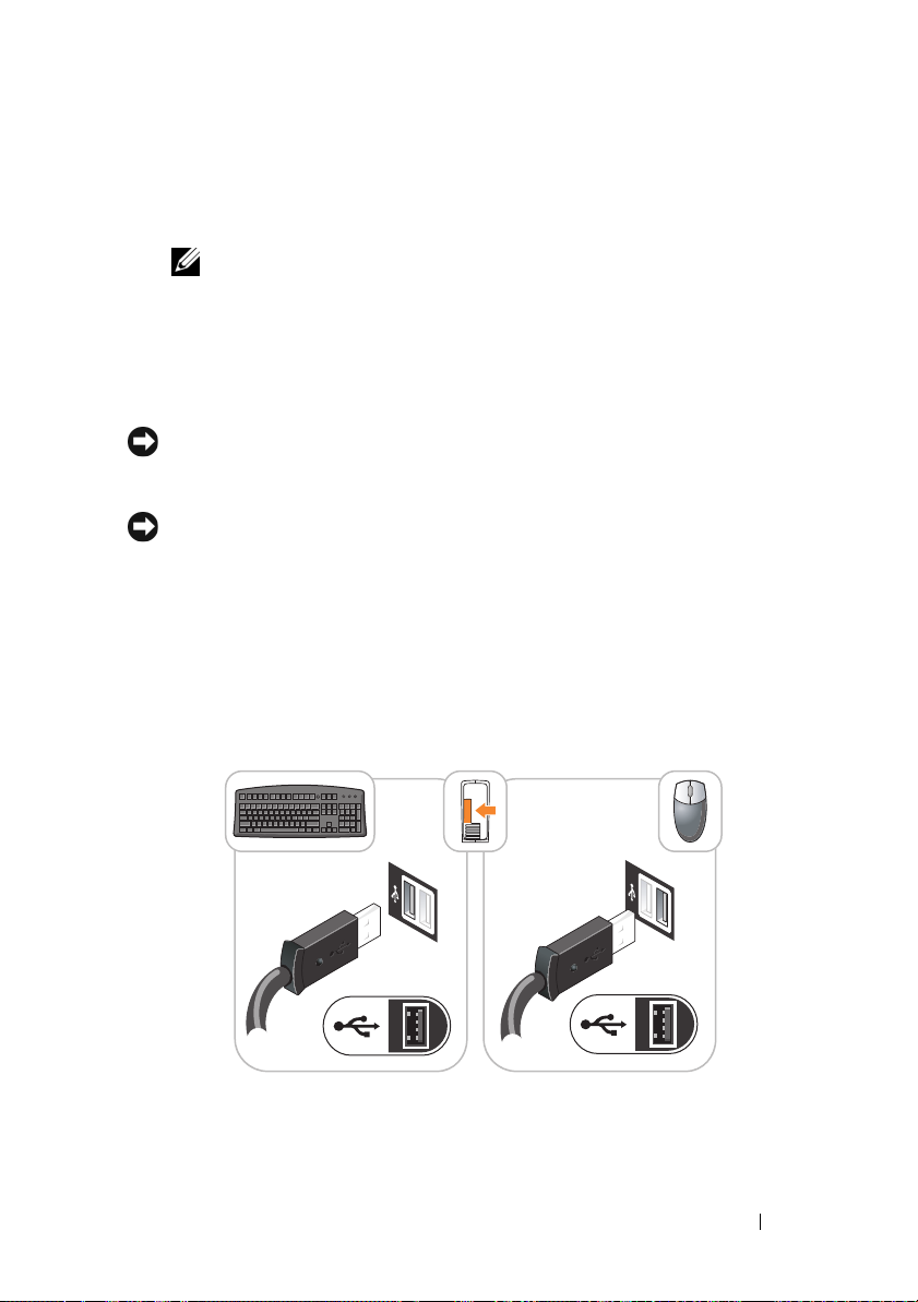
NOTICE: Do not attempt to operate a PS/2 mouse and a USB mouse simultaneously.
1
Connect the keyboard and mouse.
NOTICE: Do not connect a modem cable to the network adapter connector.
Voltage from telephone communications can cause damage to the network adapter
2
Connect the modem or network cable.
Insert the network cable, not the telephone line, into the network
connector. If you have an optional modem, connect the telephone line to
the modem.
10 Quick Reference Guide
3
Connect the monitor.
Align and gently insert the monitor cable to avoid bending connector pins.
Tighten the thumbscrews on the cable connectors.
NOTE: Some monitors have the video connector underneath the back of the
screen. See the documentation that came with your monitor for its connector
locations.
4
Connect the speakers.
5
Connect power cables to the computer, monitor, and devices and connect
the other ends of the power cables to electrical outlets.
NOTICE: To avoid damaging a computer with a manual voltage-selection switch,
set the switch for the voltage that most closely matches the AC power available in
your location.
NOTICE: In Japan, the voltage selection switch must be set to the 115-V position
even though the AC power available in Japan is 100 V.
6
Verify that the voltage selection switch is set correctly for your location.
Your computer has a manual voltage-selection switch. Computers with a
voltage selection switch on the back panel must be manually set to operate
at the correct operating voltage.
Set Up Your Keyboard and Mouse
Quick Reference Guide 11
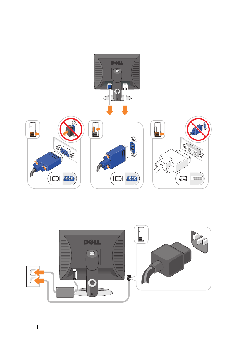
Set Up Your Monitor
Power Connections
12 Quick Reference Guide

Before You Begin
This chapter provides procedures for removing and installing the components
in your computer. Unless otherwise noted, each procedure assumes that the
following conditions exist:
• You have performed the steps in "Turning Off Your Computer" on page 13
and "Mini Tower Computer" on page 16.
• You have read the safety information in your Dell™
Guide.
• A component can be replaced by performing the removal procedure in
reverse order.
Recommended Tools
The procedures in this document may require the following tools:
• Small flat-blade screwdriver
• Phillips screwdriver
• Flash BIOS update program floppy disk or CD
Turning Off Your Computer
NOTICE: To avoid losing data, save and close all open files and exit all open
programs before you turn off your computer.
1
Shut down the operating system:
a
Save and close all open files and exit all open programs.
b
In the Microsoft® Windows® XP operating system
Down
→ Shut down
.
Product Information
, click
Start→
Shut
In the Microsoft® Windows Vista™ operating system,
Windows Vista Start Button , in the lower-left corner of the
desktop, click the arrow in the lower-right corner of the Start menu as
shown below, and then click
The computer turns off after the operating system shutdown process is
complete.
Shut Down
Quick Reference Guide 13
.
click the

NOTICE: Ensure that the computer and all attached devices are turned off. If your
computer and attached devices did not automatically turn off when you shut down
your operating system, press and hold the power button for about 4 seconds to turn
them off.
Before Working Inside Your Computer
Use the following safety guidelines to help protect your computer from
potential damage and to help ensure your own personal safety.
CAUTION: Before you begin any of the procedures in this section, follow the
safety instructions in the Product Information Guide.
CAUTION: Handle components and cards with care. Do not touch the components
or contacts on a card. Hold a card by its edges or by its metal mounting bracket.
Hold a component such as a processor by its edges, not by its pins.
NOTICE: Only a certified service technician should perform repairs on your
computer. Damage due to servicing that is not authorized by Dell is not covered by
your warranty.
NOTICE: When you disconnect a cable, pull on its connector or on its strain-relief
loop, not on the cable itself. Some cables have a connector with locking tabs; if you
are disconnecting this type of cable, press in on the locking tabs before you
disconnect the cable. As you pull connectors apart, keep them evenly aligned to
avoid bending any connector pins. Also, before you connect a cable, ensure that
both connectors are correctly oriented and aligned.
NOTICE: To avoid damaging the computer, perform the following steps before you
begin working inside the computer.
1
Turn off your computer.
2
If the computer is connected to a docking device (docked), undock it. See
the documentation that came with your docking device for instructions.
NOTICE: To disconnect a network cable, first unplug the cable from your computer
and then unplug it from the network wall jack.
3
Disconnect all telephone or network cables from the computer.
4
Disconnect your computer and all attached devices from their electrical
outlets, and then press the power button to ground the system board.
5
If applicable, remove the computer stand (for instructions, see the
documentation that came with the stand) and the cable cover, if attached
(see "Cable Cover (Optional)" on page 57).
14 Quick Reference Guide

CAUTION: To guard against electrical shock, always unplug your computer from
the electrical outlet before removing the cover.
6
Remove the computer cover.
• For a mini tower computer, see "Removing the Computer Cover" on
page 22.
• For a desktop computer, see "Removing the Computer Cover" on
page 32.
• For a small form factor computer, see "Removing the Computer
Cover" on page 43.
• For an ultra small form factor computer, see "Removing the Computer
Cover" on page 55.
NOTICE: Before touching anything inside your computer, ground yourself by
touching an unpainted metal surface, such as the metal at the back of the computer.
While you work, periodically touch an unpainted metal surface to dissipate any
static electricity that could harm internal components.
Quick Reference Guide 15
Mini Tower Computer
System Views
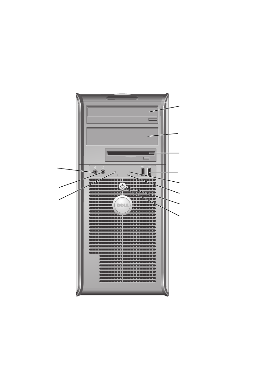
Front View
1
2
3
11
10
9
1 5.25-inch drive
bay
2 5.25-inch drive
bay
4
5
6
7
8
Can contain an optical drive. Insert a CD or DVD
(if supported) into this drive.
Can contain an optical drive. Insert a CD or DVD
(if supported) into this drive.
16 Quick Reference Guide

3 3.5-inch drive
bay
4 USB 2.0
connectors (2)
5 LAN indicator
light
6 diagnostic lights Use the lights to help you troubleshoot a computer problem
7 power button Press this button to turn on the computer.
Can contain an optional floppy drive or optional media card
reader.
Use the front USB connectors for devices that you connect
occasionally, such as joysticks or cameras, or for bootable
USB devices (see your online User’s Guide for more
information on booting to a USB device).
It is recommended that you use the back USB connectors
for devices that typically remain connected, such as printers
and keyboards.
This light indicates that a LAN (local area network)
connection is established.
based on the diagnostic code. For more information, see
"Diagnostic Lights" on page 66.
NOTICE: To avoid losing data, do not turn off the
computer by pressing the power button. Instead,
perform an operating system shutdown. See
Off Your Computer
NOTICE: If your operating system has ACPI enabled,
when you press the power button the computer will
perform an operating system shutdown.
" on page 13 for more information.
"Turning
Quick Reference Guide 17

8 power light The power light illuminates and blinks or remains solid to
indicate different operating modes:
• No light — The computer is turned off.
• Steady green — The computer is in a normal operating
state.
• Blinking green — The computer is in a power-saving mode
• Blinking or solid amber — The computer is receiving
electrical power, but an internal power problem may exist
9 hard drive
activity light
10 headphone
connector
11 microphone
connector
(see "Power Problems" in the
To exit from a power-saving mode, press the power button or
use the keyboard or the mouse if it is configured as a wake
device in the Windows Device Manager. For more
information about sleep modes and pwoer-saving mode, see
"Advanced Features’ in the User’s Guide.
See "Diagnostic Lights" on page 66 for a description of light
codes that can help you troubleshoot problems with your
computer.
This light flickers when the hard drive is being accessed.
Use the headphone connector to attach headphones and
most kinds of speakers.
Use the microphone connector to attach a microphone.
User’s Guide
).
18 Quick Reference Guide
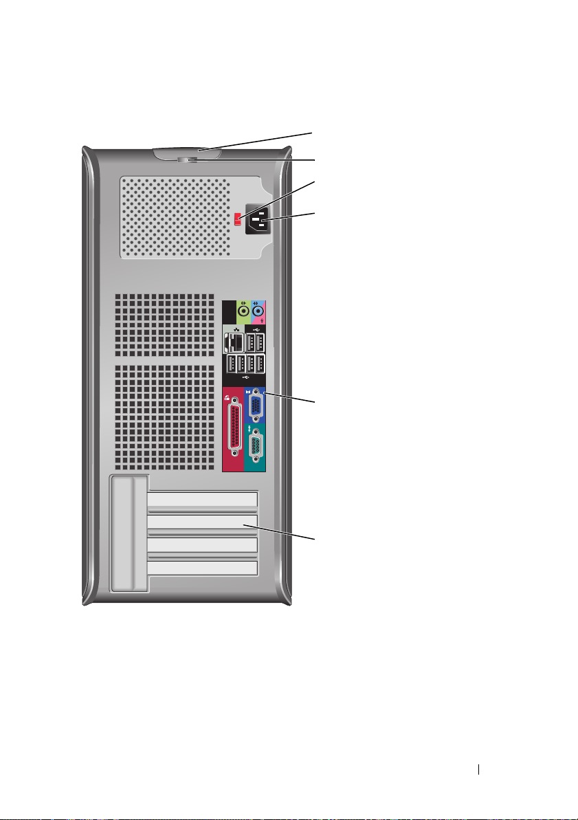
Back View
1
2
3
4
5
6
1 cover-release
latch
2 padlock ring Insert a padlock to lock the computer cover.
This latch allows you to open the computer cover.
Quick Reference Guide 19
3 voltage selection
switch
4 power connector Insert the power cable.
5 back panel
connectors
6 card slots (4) Access connectors for any installed PCI or PCI Express cards,
Your computer is equipped with a manual voltage-selection
switch. To help avoid damaging a computer with a manual
voltage-selection switch, set the switch for the voltage that
most closely matches the AC power available in your
location.
NOTICE: In Japan, the voltage selection switch must be
set to the 115-V position.
Also, ensure that your monitor and attached devices are
electrically rated to operate with the AC power available in
your location.
Plug serial, USB, and other devices into the appropriate
connectors. See "Back Panel Connectors" on page 20.
PS/2 connector, eSATA connector, etc.
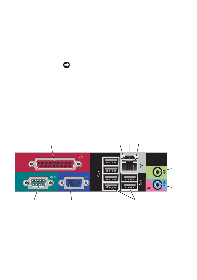
Back Panel Connectors
13
98 7
1 parallel connector Connect a parallel device, such as a printer, to the parallel
connector. If you have a USB printer, plug it into a USB
connector.
24
NOTE: The integrated parallel connector is automatically
disabled if the computer detects an installed card containing a
parallel connector configured to the same address. For more
information, see "System Setup Options" in the User’s Guide.
20 Quick Reference Guide
5
6

2 link integrity light
3 network adapter
connector
4 network activity
light
5 line-out
connector
6 line-
in/microphone
connector
7 USB 2.0
connectors (6)
• Green — A good connection exists between a 10-Mbps
network and the computer.
• Orange — A good connection exists between a 100-Mbps
network and the computer.
• Yellow — A good connection exists between a 1-Gbps
(or 1000-Mbps) network and the computer.
• Off — The computer is not detecting a physical
connection to the network.
To attach your computer to a network or broadband device,
connect one end of a network cable to either a network jack
or your network or broadband device. Connect the other
end of the network cable to the network adapter connector
on the back panel of your computer. A click indicates that
the network cable has been securely attached.
NOTE: Do not plug a telephone cable into the network
connector.
Remote management features require use of the onboard
NIC.
It is recommended that you use Category 5 wiring and
connectors for your network. If you must use Category 3
wiring, force the network speed to 10 Mbps to ensure
reliable operation.
Flashes a yellow light when the computer is transmitting or
receiving network data. A high volume of network traffic
may make this light appear to be in a steady "on" state.
Use the green line-out connector to attach headphones and
most speakers with integrated amplifiers.
Use the blue and pink line-in/microphone connector to
attach a record/playback device such as a cassette player, CD
player, or VCR.; or a personal computer microphone for
voice or musical input into a sound or telephony program.
Use the back USB connectors for devices that typically
remain connected, such as printers and keyboards.
Quick Reference Guide 21

8 video connector Plug the cable from your VGA-compatible monitor into the
blue connector.
NOTE: If you purchased an optional graphics card, this
connector will be covered by a cap. Connect your monitor to
the connector on the graphics card. Do not remove the cap.
NOTE: If you are using a graphics card that supports dual
monitors, use the y-cable that came with your computer.
9 serial connector Connect a serial device, such as a handheld device, to the
serial port. The default designations are COM1 for serial
connector 1 and COM2 for serial connector 2.
For more information, see "System Setup Options" in the
User’s Guide.
Removing the Computer Cover
CAUTION: Before you begin any of the procedures in this section, follow the
safety instructions located in the Product Information Guide.
CAUTION: To guard against electrical shock, always unplug your computer from
the electrical outlet before removing the computer cover.
1
Follow the procedures in "Before You Begin" on page 13.
2
Lay the computer on its side as shown in the illustration.
3
Locate the cover release latch shown in the illustration. Then, slide the
release latch back as you lift the cover.
4
Grip the sides of the computer cover and pivot the cover up using the
hinge tabs as leverage points.
5
Remove the cover from the hinge tabs and set it aside on a soft
nonabrasive surface.
CAUTION: Graphics card heat sinks can become very hot during normal
operation. Ensure that a graphics card heat sink has had sufficient time to
cool before you touch it.
22 Quick Reference Guide
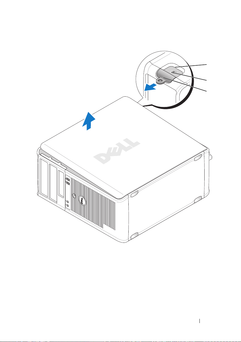
1
2
3
1 security cable slot 2 cover release latch
3 padlock ring
Quick Reference Guide 23
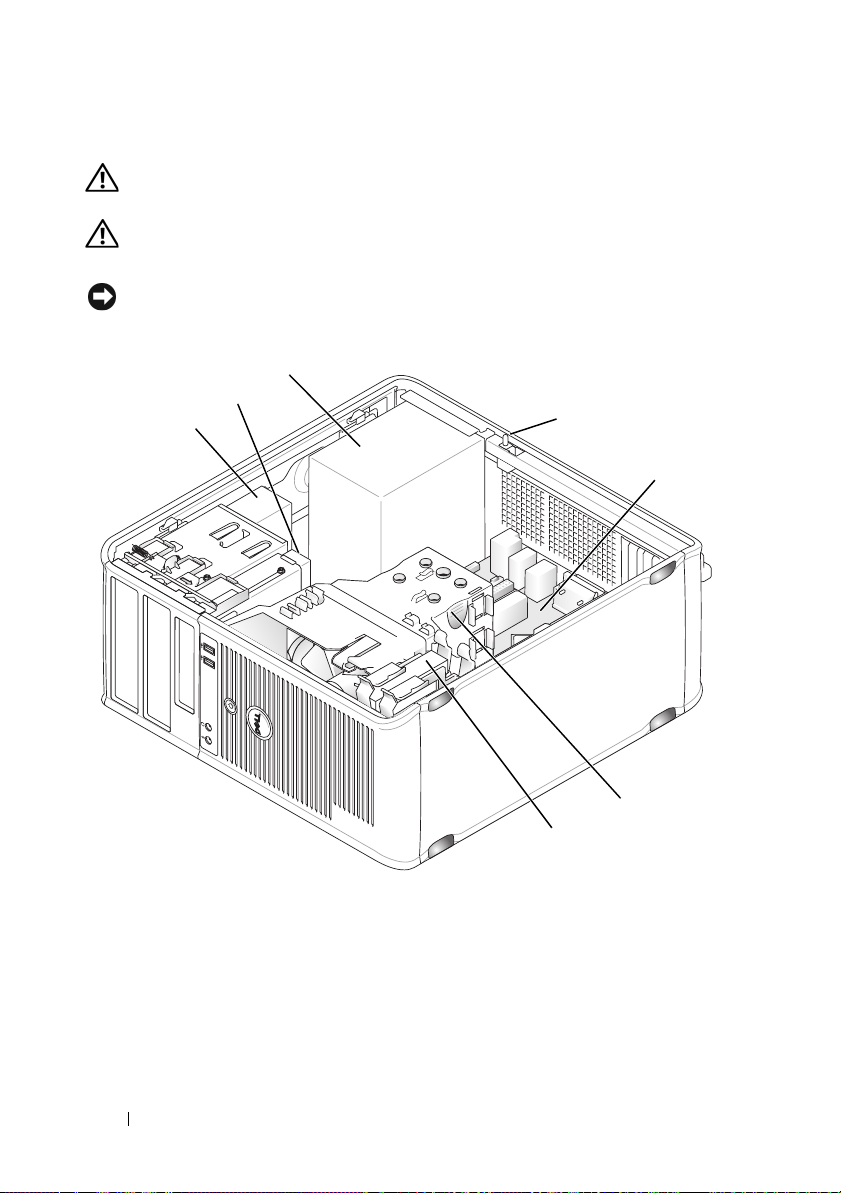
Inside Your Computer
CAUTION: Before you begin any of the procedures in this section, follow the
safety instructions located in the Product Information Guide.
CAUTION: To avoid electrical shock, always unplug your computer from the
electrical outlet before removing the computer cover.
NOTICE: Be careful when opening the computer cover to ensure that you do not
accidentally disconnect cables from the system board.
3
2
1
4
5
1 optical drive 2 disk drive
3 power supply 4 optional chassis-intrusion
5 system board 6 heat sink assembly
7 hard drive
24 Quick Reference Guide
6
7
switch
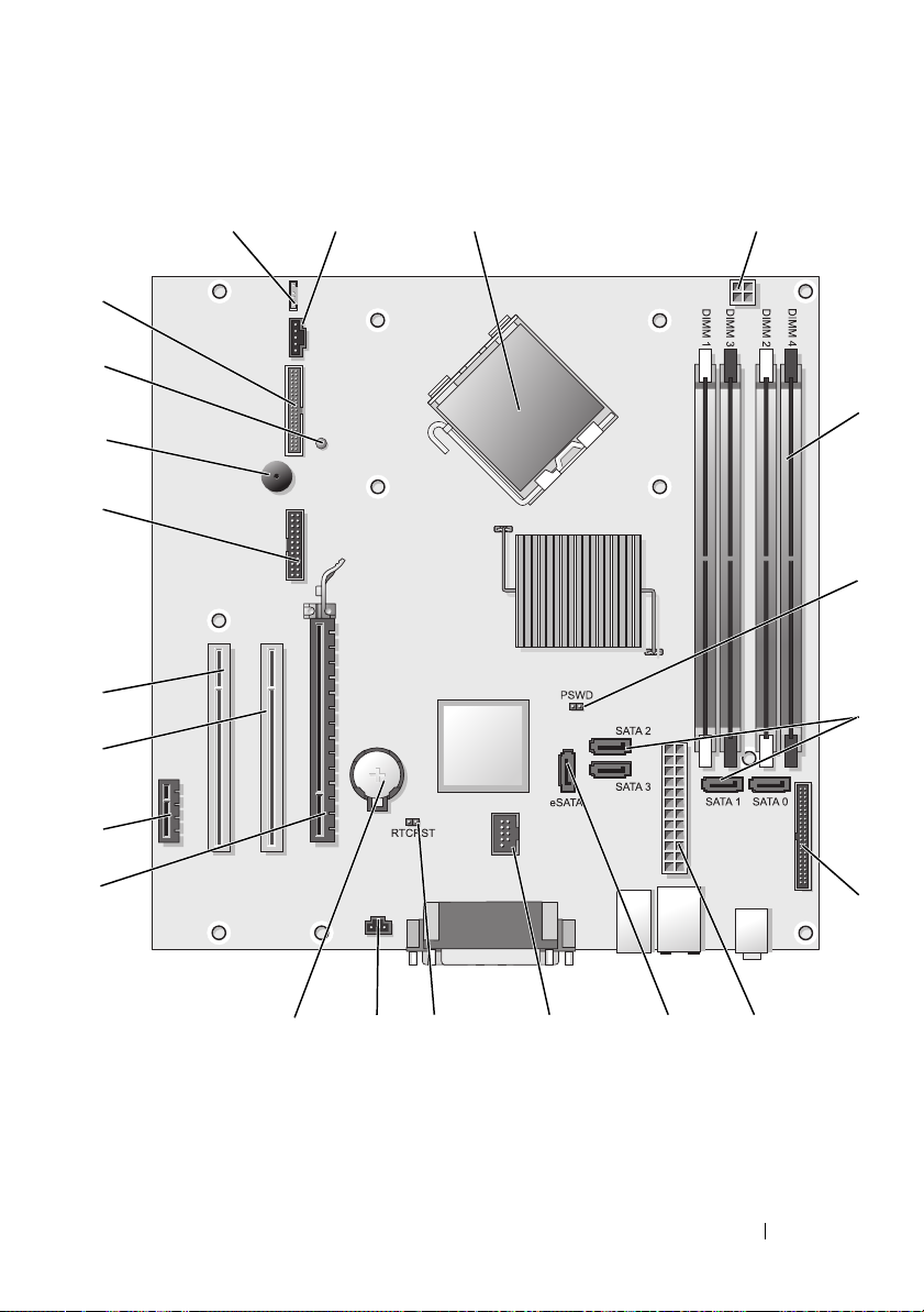
System Board Components
1
22
21
20
19
18
17
16
2
3
4
5
6
7
15
14 12
13
11
Quick Reference Guide 25
910
8
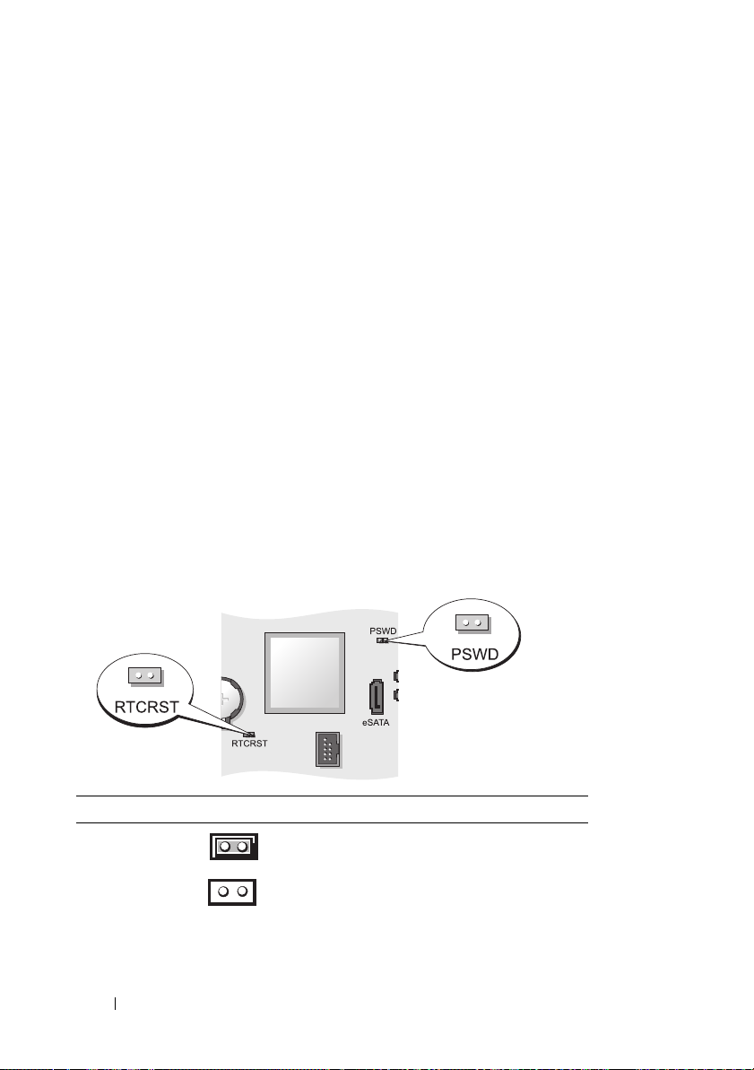
1 speaker connector (INT_SPKR) 12 RTC reset jumper (RTCRST)
2 fan (FAN_CPU) 13 intrusion switch connector
(INTRUDER)
3 processor connector (CPU) 14 battery socket (BATTERY)
4 processor power connector
(12VPOWER)
5 memory module connectors
(DIMM_1, DIMM_2, DIMM_3,
DIMM_4)
6 password jumper (PSWD) 17 PCI connector (SLOT2)
7 SATA drive connectors (SATA0,
SATA1, SATA2, SATA3)
8 front-panel connector (FRONTPANEL) 19 serial connector (SERIAL2)
9 power connector (POWER) 20 system board speaker (BEEP)
10 external SATA connector (eSATA) 21 aux power LED (AUX_LED)
11 internal USB (INT_USB) 22 floppy connector (DSKT)
15 PCI Express x16 connector (SLOT1)
16 PCI Express x1 connector (SLOT4)
18 PCI connector (SLOT3)
Jumper Settings
Jumper Setting Description
PSWD Password features are enabled
(default setting).
Password features are disabled.
26 Quick Reference Guide
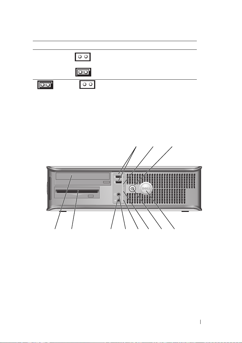
Jumper Setting Description
RTCRST The real-time clock has not been
reset.
jumpered unjumpered
The real-time clock is being reset
(jumpered temporarily).
Desktop Computer
System Views
Front View
1 USB 2.0
connectors (2)
2 LAN indicator
light
2
89
7
Use the front USB connectors for devices that you connect
occasionally, such as joysticks or cameras, or for bootable
USB devices (see "System Setup"
more information about booting to a USB device).
It is recommended that you use the back USB connectors
for devices that typically remain connected, such as
printers and keyboards.
This light indicates that a LAN (local area network)
connection is established.
514611 10
in the
3
User’s Guide
for
Quick Reference Guide 27

3 power button Press this button to turn on the computer.
NOTICE: To avoid losing data, do not turn off the
computer by pressing the power button. Instead,
perform an operating system shutdown. See "Turning
Off Your Computer" in the User’s Guide for more
information.
NOTICE: If your operating system has ACPI enabled,
when you press the power button the computer will
perform an operating system shutdown.
4 Dell badge This badge can be rotated to match the orientation of your
computer. To rotate, place fingers around the outside of
the badge, press firmly, and turn the badge. You can also
rotate the badge using the slot provided near the bottom of
the badge.
5 power light The power light illuminates and blinks or remains solid to
indicate different operating states:
• No light — The computer is turned off.
• Steady green — The computer is in a normal operating
state.
• Blinking green — The computer is in a power-saving
mode.
• Blinking or solid amber — See "Power Problems" in the
User’s Guide
To exit from a power-saving mode, press the power button
or use the keyboard or the mouse if it is configured as a
wake device in the Windows Device Manager. For more
information about sleep modes and exiting from a powersaving mode, see
Vista" in the
See "Diagnostic Lights" on page 66 for a description of
light codes that can help you troubleshoot problems with
your computer.
6 diagnostic lights Use the lights to help you troubleshoot a computer
problem based on the diagnostic code. For more
information, see "Diagnostic Lights" on page 66.
7 hard drive
activity light
This light flickers when the hard drive is being accessed.
.
"Power Management for Windows XP and
User’s Guide
.
28 Quick Reference Guide
8 headphone
connector
9 microphone
connector
10 3.5-inch drive
bay
11 5.25-inch drive
bay
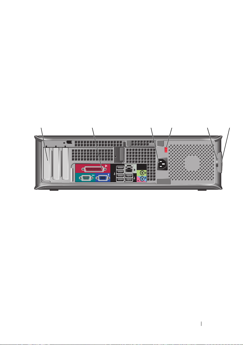
Back View
Use the headphone connector to attach headphones and
most kinds of speakers.
Use the microphone connector to attach a microphone.
Can contain an optional floppy drive, second hard drive, or
optional media card reader.
Can contain an optical drive. Insert a CD or DVD
(if supported) into this drive.
1
1 card slots (3) Access connectors for any installed PCI or PCI Express
2 3 4 6
cards, PS/2 connector, eSATA connector, etc.
NOTE: The back view of the system will be different if a riser is
installed.
2 back panel
connectors
3 power connector Insert the power cable.
Plug serial, USB, and other devices into the appropriate
connectors (see "Back Panel Connectors" on page 30).
5
Quick Reference Guide 29
4 voltage selection
switch
5 padlock ring Insert a padlock to lock the computer cover.
6 cover-release
latch
Your computer is equipped with a manual voltage selection
switch. To help avoid damaging a computer with a manual
voltage selection switch, set the switch for the voltage that
most closely matches the AC power available in your
location.
NOTICE: In Japan, the voltage selection switch must be
set to the 115-V position.
Also, ensure that your monitor and attached devices are
electrically rated to operate with the AC power available in
your location.
Allows you to open the computer cover.
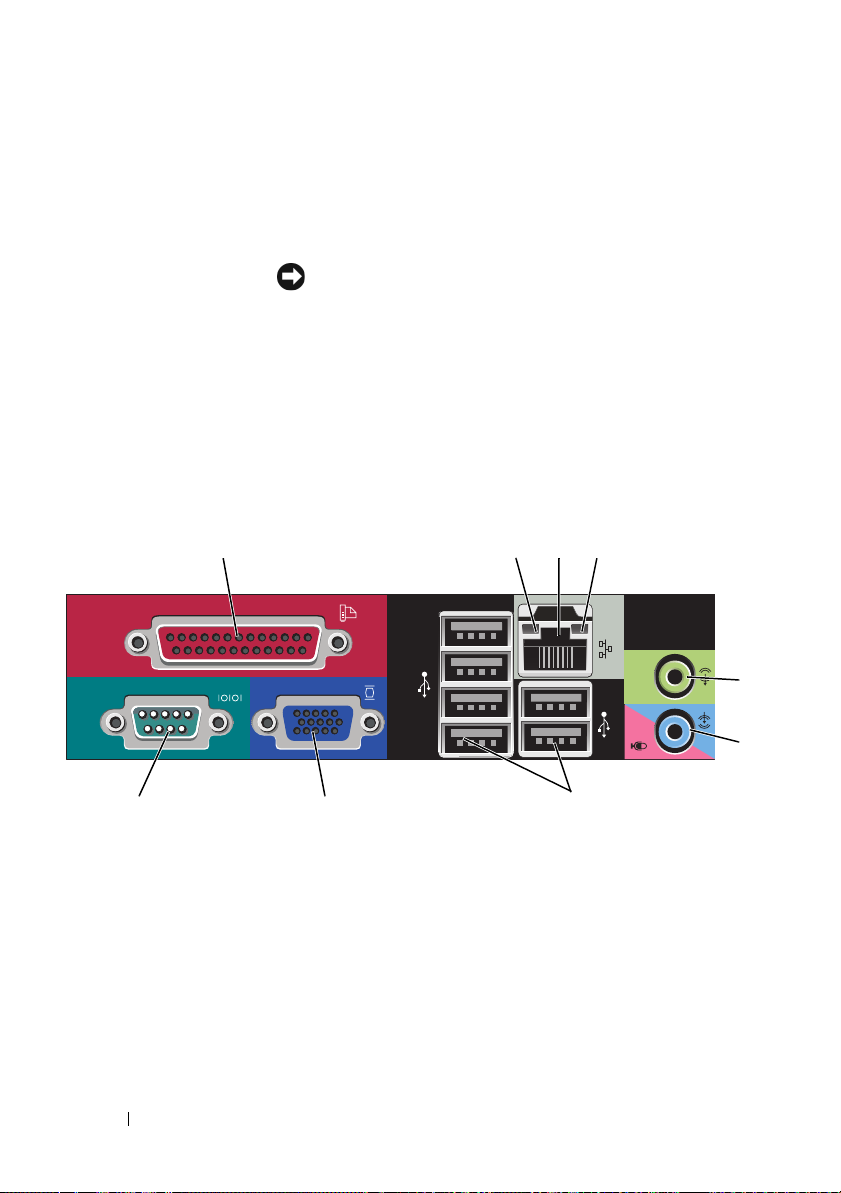
Back Panel Connectors
13
98 7
1 parallel connector Connect a parallel device, such as a printer, to the parallel
connector. If you have a USB printer, plug it into a USB
connector.
24
NOTE: The integrated parallel connector is automatically
disabled if the computer detects an installed card containing a
parallel connector configured to the same address. For more
information, see "System Setup Options" in the User’s Guide.
30 Quick Reference Guide
5
6
 Loading...