

Page 1

Dell™ OptiPlex™ 755
Quick Reference Guide
Models DCTR, DCNE, DCSM, and DCCY
www.dell.com | support.dell.com
Page 2

Notes, Notices, and Cautions
NOTE: A NOTE indicates important information that helps you make better use of
your computer.
NOTICE: A NOTICE indicates either potential damage to hardware or loss of data
and tells you how to avoid the problem.
CAUTION: A CAUTION indicates a potential for property damage, personal injury,
or death.
____________________
Information in this document is subject to change without notice.
© 2007 Dell Inc. All rights reserved.
Reproduction in any manner whatsoever without the written permission of Dell Inc. is strictly
forbidden.
Trademarks used in this text: Dell, the DELL logo, OptiPlex, Inspiron, Dimension, Latitude, Dell
Precision, DellNet, TravelLi te , OpenManage, PowerVault, Axim, PowerEdge, PowerConnect,
Pow er Ap p, and StrikeZone are trademarks of Dell Inc.; Intel, Pentium, SpeedStep, and Celeron are
registered trademarks and Core and vPro are trademarks of Intel Corporation in the U.S and other
countries; Microsoft, MS-DOS, Windows, Windows Vista, and the Windows Vista Start Button are either
registered trademarks or trademarks of Microsoft Corporation in the United States and/or other
countries; IBM is a registered trademark of International Business Machines Corporation; Bluetooth
is a trademark owned by Bluetooth SIG, Inc. and is used by Dell Inc. under license. ENERGY STAR
is a registered trademark of the U.S. Environmental Protection Agency. As an ENERGY STAR partner,
Dell Inc. has determined that this product meets the ENERGY STAR guidelines for energy efficiency.
Other trademarks and trade names may be used in this document to refer to either the entities claiming
the marks and names or their products. Dell Inc. disclaims any proprietary interest in trademarks and
trade names other than its own.
Models: DCTR, DCNE, DCSM, and DCCY
July 2007 FN394 Rev. A00
Page 3

Contents
Finding Information . . . . . . . . . . . . . . . . . . . . 5
Setting Up Your Computer
. . . . . . . . . . . . . . . . 10
Set Up Your Keyboard and Mouse
Set Up Your Monitor
Power Connections
Before You Begin
Recommended Tools
. . . . . . . . . . . . . . . . 12
. . . . . . . . . . . . . . . . 12
. . . . . . . . . . . . . . . . . . . . 13
. . . . . . . . . . . . . . . . 13
Turning Off Your Computer
Before Working Inside Your Computer
Mini Tower Computer
System Views
. . . . . . . . . . . . . . . . . . 16
. . . . . . . . . . . . . . . . . . . . 16
Removing the Computer Cover
Inside Your Computer
. . . . . . . . . . . . . . . 24
System Board Components
Jumper Settings
Desktop Computer
System Views
. . . . . . . . . . . . . . . . . . 26
. . . . . . . . . . . . . . . . . . . . 27
. . . . . . . . . . . . . . . . . . . . 27
Removing the Computer Cover
Inside Your Computer
. . . . . . . . . . . . . . . 33
System Board Components
Jumper Settings
. . . . . . . . . . . . . . . . . . 36
. . . . . . . . . 11
. . . . . . . . . . . . . 13
. . . . . . . 14
. . . . . . . . . . . 22
. . . . . . . . . . . . 25
. . . . . . . . . . . 32
. . . . . . . . . . . . 35
Small Form Factor Computer
System Views
. . . . . . . . . . . . . . . . . . . . 37
Removing the Computer Cover
. . . . . . . . . . . . . . 37
. . . . . . . . . . . 43
Contents 3
Page 4

Inside Your Computer . . . . . . . . . . . . . . . . 44
System Board Components
Jumper Settings
. . . . . . . . . . . . . . . . . . 47
. . . . . . . . . . . . . 46
Ultra Small Form Factor Computer
System Views
. . . . . . . . . . . . . . . . . . . . 48
Removing the Computer Cover
Inside Your Computer
Cable Cover (Optional)
System Board Components
Jumper Settings
Solving Problems
Dell Diagnostics
System Lights
Diagnostic Lights
Beep Codes
. . . . . . . . . . . . . . . . . . . . . 70
. . . . . . . . . . . . . . . . 56
. . . . . . . . . . . . . . . 57
. . . . . . . . . . . . . . . 59
. . . . . . . . . . . . . . . . . . 60
. . . . . . . . . . . . . . . . . . . . 61
. . . . . . . . . . . . . . . . . . 61
. . . . . . . . . . . . . . . . . . . . 65
. . . . . . . . . . . . . . . . . . 66
Resolving Software and Hardware
Incompatibilities
. . . . . . . . . . . . . . . . . . 72
Restoring Your Operating System
Using Microsoft
Windows System Restore . . . . 73
Using Dell™ PC Restore and Dell Factory
Image Restore
. . . . . . . . . . . . . . . . . . . 75
Using the Drivers and Utilities Media
Reinstalling Drivers and Utilities
. . . . . . . . . . . 48
. . . . . . . . . . . 55
. . . . . . . . . 73
. . . . . . . 78
. . . . . . . . . . 79
Index . . . . . . . . . . . . . . . . . . . . . . . . . . . . . . . 83
4 Contents
Page 5
Finding Information
NOTE: Some features or media may be optional and may not ship with your
computer. Some features or media may not be available in certain countries.
NOTE: Additional information may ship with your computer.
What Are You Looking For? Find It Here
• A diagnostic program for my computer
• Drivers for my computer
• Desktop System Software (DSS)
Drivers and Utilities Media
NOTE: The Drivers and Utilities media may
be optional and may not ship with your
computer.
Documentation and drivers are already
installed on your computer. You can use
the media to reinstall drivers (see
"Reinstalling Drivers and Utilities" on
page 79), to run the Dell Diagnostics (see
"Dell Diagnostics" on page 61).
Readme files may be included on your
media to provide last-minute updates
about technical changes to your computer
or advanced technical-reference material
for technicians or experienced users.
NOTE: Drivers and documentation updates
can be found at support.dell.com.
Quick Reference Guide 5
Page 6
What Are You Looking For? Find It Here
• How to set up my computer
• How to run the Dell Diagnostics
• Error codes and diagnostic lights
• Tools and utilities
• How to set up a printer
• How to troubleshoot and solve problems
• How to remove and install parts
Owner’s Manual
NOTE: This document may be optional and
may not ship with your computer.
NOTE: This document is available as a PDF
at support.dell.com.
• Warranty information
• Terms and Conditions (U.S. only)
• Safety instructions
• Regulatory information
• Ergonomics information
• End User License Agreement
Dell™ Product Information Guide
• How to remove and replace parts
• Specifications
• How to configure system settings
• How to troubleshoot and solve problems
6 Quick Reference Guide
Dell™ OptiPlex™ User’s Guide
Microsoft Windows Help and Support
Center
1
Click
Start
or
→
Help and
→
Support
Guides
2
Click the
computer.
Dell User and System
→
System Guides
User’s Guide
for your
.
Page 7
What Are You Looking For? Find It Here
• Service Tag and Express Service Code
• Microsoft Windows License Label
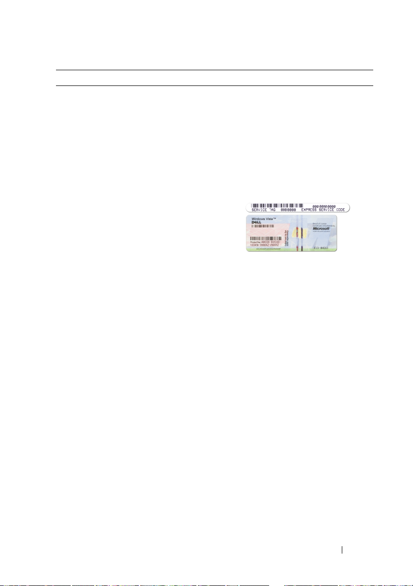
Service Tag and Microsoft® Windows®
License
These labels are located on your
computer.
• Use the Service Tag to identify your
computer when you use
support.dell.com
• Enter the Express Service Code to direct
your call when contacting support.
NOTE: As an increased security measure,
the newly designed Microsoft Windows
license label incorporates a missing portion
or "hole" to discourage removal of the label.
or contact support.
Quick Reference Guide 7
Page 8

What Are You Looking For? Find It Here
• Solutions — Troubleshooting hints and
tips, articles from technicians, and
online courses, frequently asked
questions
Dell Support Website — support.dell.com
NOTE: Select your region or business
segment to view the appropriate support
site.
• Community — Online discussion with
other Dell customers
• Upgrades — Upgrade information for
components, such as memory, the hard
drive, and the operating system
• Customer Care — Contact information,
service call and order status, warranty,
and repair information
• Service and support — Service call
status and support history, service
contract, online discussions with
technical support
• Dell Technical Update Service —
Proactive e-mail notification of software
and hardware updates for your computer
• Reference — Computer documentation,
details on my computer configuration,
product specifications, and white papers
• Downloads — Certified drivers, patches,
and software updates
• Desktop System Software (DSS)— If
you reinstall the operating system for
your computer, you should also reinstall
the DSS utility. DSS provides critical
updates for your operating system and
support for processors, optical drives,
USB devices, and so on. DSS is
necessary for correct operation of your
Dell computer. The software
automatically detects your computer
and operating system and installs the
updates appropriate for your
configuration.
To download Desktop System Software:
1
Go to
support.dell.com
Drivers & Downloads.
2
Enter your Service Tag or Product Type
and Product Model, and click
3
Scroll to
Utilities
Software
4
Select
Go
click
NOTE: The support.dell.com user interface
may vary depending on your selections.
and click
Go
System and Configuration
→
Dell Notebook System
and click
Drivers & Downloads
Download Now
and
.
.
.
8 Quick Reference Guide
Page 9
What Are You Looking For? Find It Here
• How to use Windows XP
• How to work with programs and files
• How to personalize my desktop
Windows Help and Support Center
1
To access Windows Help and Support:
• In Windows XP, click
Help and Support
• In Windows Vista™, click the
Windows Vista Start button
Help and Support
click
2
Type a word or phrase that describes
your problem, and then click the arrow
icon.
3
Click the topic that describes your
problem.
4
Follow the instructions on the screen.
• How to reinstall my operating system
Operating System Media
NOTE: The Operating System media may be
optional and may not ship with your
computer.
The operating system is already installed
on your computer. To reinstall your
operating system, use the Operating
System media. See "Restoring Your
Operating System" in your User’s Guide or
Owner’s Manual.
Start and click
.
.
and
Quick Reference Guide 9
Page 10
What Are You Looking For? Find It Here
After you reinstall your operating system,
use the Drivers and Utilities media to
reinstall drivers for the devices that came
with your computer.
Your operating system product key label is
located on your computer.
NOTE: The color of your CD varies based
on the operating system you ordered.
Setting Up Your Computer
CAUTION: Before performing any of the procedures in this section, follow the
safety instructions in Product Information Guide.
NOTICE: If your computer has an expansion card installed (such as a modem
card), connect the appropriate cable to the card, not to the connector on the back
panel.
NOTICE: To help allow the computer to maintain proper operating temperature,
ensure that you do not place the computer too close to a wall or other storage
compartment that might prevent air circulation around the chassis. See your
Product Information Guide for more information.
NOTE: Before you install any devices or software that did not ship with your
computer, read the documentation that came with the device or software, or
contact the vendor to verify that the device or software is compatible with your
computer and operating system.
You must complete all the steps to properly set up your computer. See the
appropriate figures that follow the instructions.
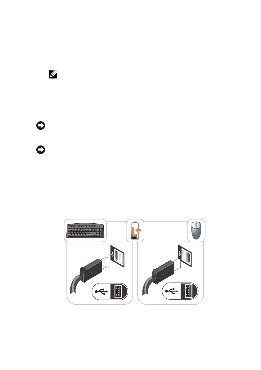
NOTICE: Do not attempt to operate a PS/2 mouse and a USB mouse simultaneously.
1
Connect the keyboard and mouse.
NOTICE: Do not connect a modem cable to the network adapter connector.
Voltage from telephone communications can cause damage to the network adapter
2
Connect the modem or network cable.
Insert the network cable, not the telephone line, into the network
connector. If you have an optional modem, connect the telephone line to
the modem.
10 Quick Reference Guide
Page 11
3
Connect the monitor.
Align and gently insert the monitor cable to avoid bending connector pins.
Tighten the thumbscrews on the cable connectors.
NOTE: Some monitors have the video connector underneath the back of the
screen. See the documentation that came with your monitor for its connector
locations.
4
Connect the speakers.
5
Connect power cables to the computer, monitor, and devices and connect
the other ends of the power cables to electrical outlets.
NOTICE: To avoid damaging a computer with a manual voltage-selection switch,
set the switch for the voltage that most closely matches the AC power available in
your location.
NOTICE: In Japan, the voltage selection switch must be set to the 115-V position
even though the AC power available in Japan is 100 V.
6
Verify that the voltage selection switch is set correctly for your location.
Your computer has a manual voltage-selection switch. Computers with a
voltage selection switch on the back panel must be manually set to operate
at the correct operating voltage.
Set Up Your Keyboard and Mouse
Quick Reference Guide 11
Page 12
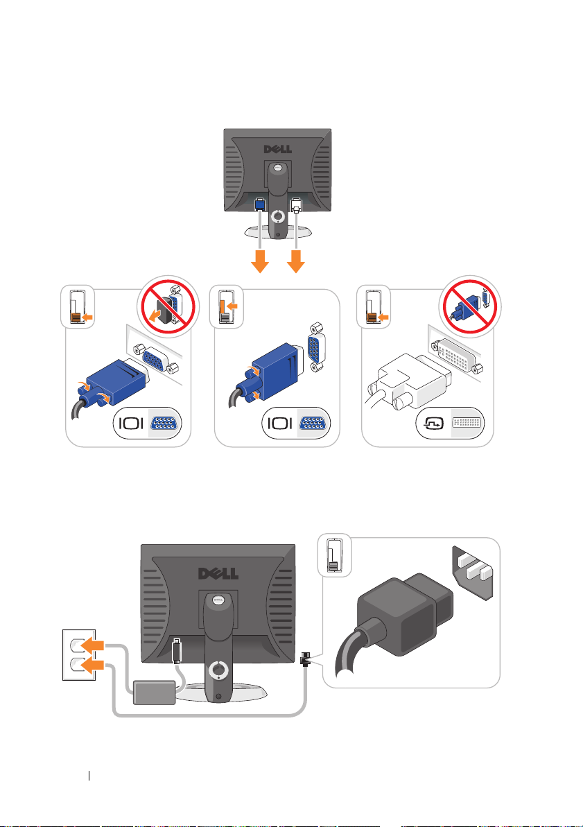
Set Up Your Monitor
Power Connections
12 Quick Reference Guide
Page 13

Before You Begin
This chapter provides procedures for removing and installing the components
in your computer. Unless otherwise noted, each procedure assumes that the
following conditions exist:
• You have performed the steps in "Turning Off Your Computer" on page 13
and "Mini Tower Computer" on page 16.
• You have read the safety information in your Dell™
Guide.
• A component can be replaced by performing the removal procedure in
reverse order.
Recommended Tools
The procedures in this document may require the following tools:
• Small flat-blade screwdriver
• Phillips screwdriver
• Flash BIOS update program floppy disk or CD
Turning Off Your Computer
NOTICE: To avoid losing data, save and close all open files and exit all open
programs before you turn off your computer.
1
Shut down the operating system:
a
Save and close all open files and exit all open programs.
b
In the Microsoft® Windows® XP operating system
Down
→ Shut down
.
Product Information
, click
Start→
Shut
In the Microsoft® Windows Vista™ operating system,
Windows Vista Start Button , in the lower-left corner of the
desktop, click the arrow in the lower-right corner of the Start menu as
shown below, and then click
The computer turns off after the operating system shutdown process is
complete.
Shut Down
Quick Reference Guide 13
.
click the
Page 14

NOTICE: Ensure that the computer and all attached devices are turned off. If your
computer and attached devices did not automatically turn off when you shut down
your operating system, press and hold the power button for about 4 seconds to turn
them off.
Before Working Inside Your Computer
Use the following safety guidelines to help protect your computer from
potential damage and to help ensure your own personal safety.
CAUTION: Before you begin any of the procedures in this section, follow the
safety instructions in the Product Information Guide.
CAUTION: Handle components and cards with care. Do not touch the components
or contacts on a card. Hold a card by its edges or by its metal mounting bracket.
Hold a component such as a processor by its edges, not by its pins.
NOTICE: Only a certified service technician should perform repairs on your
computer. Damage due to servicing that is not authorized by Dell is not covered by
your warranty.
NOTICE: When you disconnect a cable, pull on its connector or on its strain-relief
loop, not on the cable itself. Some cables have a connector with locking tabs; if you
are disconnecting this type of cable, press in on the locking tabs before you
disconnect the cable. As you pull connectors apart, keep them evenly aligned to
avoid bending any connector pins. Also, before you connect a cable, ensure that
both connectors are correctly oriented and aligned.
NOTICE: To avoid damaging the computer, perform the following steps before you
begin working inside the computer.
1
Turn off your computer.
2
If the computer is connected to a docking device (docked), undock it. See
the documentation that came with your docking device for instructions.
NOTICE: To disconnect a network cable, first unplug the cable from your computer
and then unplug it from the network wall jack.
3
Disconnect all telephone or network cables from the computer.
4
Disconnect your computer and all attached devices from their electrical
outlets, and then press the power button to ground the system board.
5
If applicable, remove the computer stand (for instructions, see the
documentation that came with the stand) and the cable cover, if attached
(see "Cable Cover (Optional)" on page 57).
14 Quick Reference Guide
Page 15

CAUTION: To guard against electrical shock, always unplug your computer from
the electrical outlet before removing the cover.
6
Remove the computer cover.
• For a mini tower computer, see "Removing the Computer Cover" on
page 22.
• For a desktop computer, see "Removing the Computer Cover" on
page 32.
• For a small form factor computer, see "Removing the Computer
Cover" on page 43.
• For an ultra small form factor computer, see "Removing the Computer
Cover" on page 55.
NOTICE: Before touching anything inside your computer, ground yourself by
touching an unpainted metal surface, such as the metal at the back of the computer.
While you work, periodically touch an unpainted metal surface to dissipate any
static electricity that could harm internal components.
Quick Reference Guide 15
Page 16
Mini Tower Computer
System Views
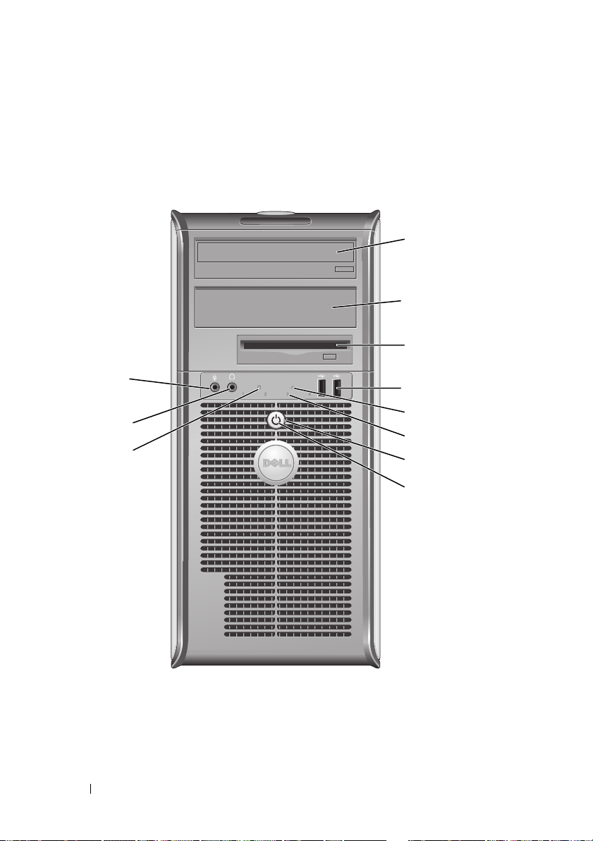
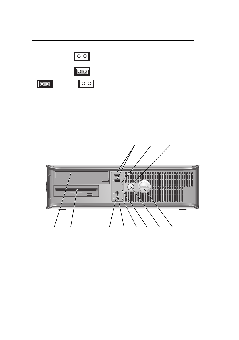
Front View
1
2
3
11
10
9
1 5.25-inch drive
bay
2 5.25-inch drive
bay
4
5
6
7
8
Can contain an optical drive. Insert a CD or DVD
(if supported) into this drive.
Can contain an optical drive. Insert a CD or DVD
(if supported) into this drive.
16 Quick Reference Guide
Page 17

3 3.5-inch drive
bay
4 USB 2.0
connectors (2)
5 LAN indicator
light
6 diagnostic lights Use the lights to help you troubleshoot a computer problem
7 power button Press this button to turn on the computer.
Can contain an optional floppy drive or optional media card
reader.
Use the front USB connectors for devices that you connect
occasionally, such as joysticks or cameras, or for bootable
USB devices (see your online User’s Guide for more
information on booting to a USB device).
It is recommended that you use the back USB connectors
for devices that typically remain connected, such as printers
and keyboards.
This light indicates that a LAN (local area network)
connection is established.
based on the diagnostic code. For more information, see
"Diagnostic Lights" on page 66.
NOTICE: To avoid losing data, do not turn off the
computer by pressing the power button. Instead,
perform an operating system shutdown. See
Off Your Computer
NOTICE: If your operating system has ACPI enabled,
when you press the power button the computer will
perform an operating system shutdown.
" on page 13 for more information.
"Turning
Quick Reference Guide 17
Page 18

8 power light The power light illuminates and blinks or remains solid to
indicate different operating modes:
• No light — The computer is turned off.
• Steady green — The computer is in a normal operating
state.
• Blinking green — The computer is in a power-saving mode
• Blinking or solid amber — The computer is receiving
electrical power, but an internal power problem may exist
9 hard drive
activity light
10 headphone
connector
11 microphone
connector
(see "Power Problems" in the
To exit from a power-saving mode, press the power button or
use the keyboard or the mouse if it is configured as a wake
device in the Windows Device Manager. For more
information about sleep modes and pwoer-saving mode, see
"Advanced Features’ in the User’s Guide.
See "Diagnostic Lights" on page 66 for a description of light
codes that can help you troubleshoot problems with your
computer.
This light flickers when the hard drive is being accessed.
Use the headphone connector to attach headphones and
most kinds of speakers.
Use the microphone connector to attach a microphone.
User’s Guide
).
18 Quick Reference Guide
Page 19
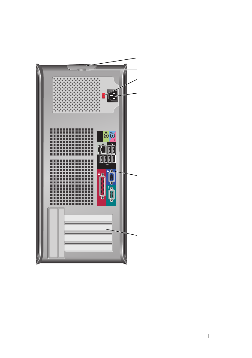
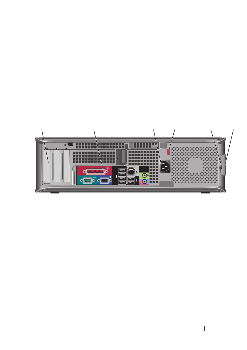
Back View
1
2
3
4
5
6
1 cover-release
latch
2 padlock ring Insert a padlock to lock the computer cover.
This latch allows you to open the computer cover.
Quick Reference Guide 19
Page 20
3 voltage selection
switch
4 power connector Insert the power cable.
5 back panel
connectors
6 card slots (4) Access connectors for any installed PCI or PCI Express cards,
Your computer is equipped with a manual voltage-selection
switch. To help avoid damaging a computer with a manual
voltage-selection switch, set the switch for the voltage that
most closely matches the AC power available in your
location.
NOTICE: In Japan, the voltage selection switch must be
set to the 115-V position.
Also, ensure that your monitor and attached devices are
electrically rated to operate with the AC power available in
your location.
Plug serial, USB, and other devices into the appropriate
connectors. See "Back Panel Connectors" on page 20.
PS/2 connector, eSATA connector, etc.
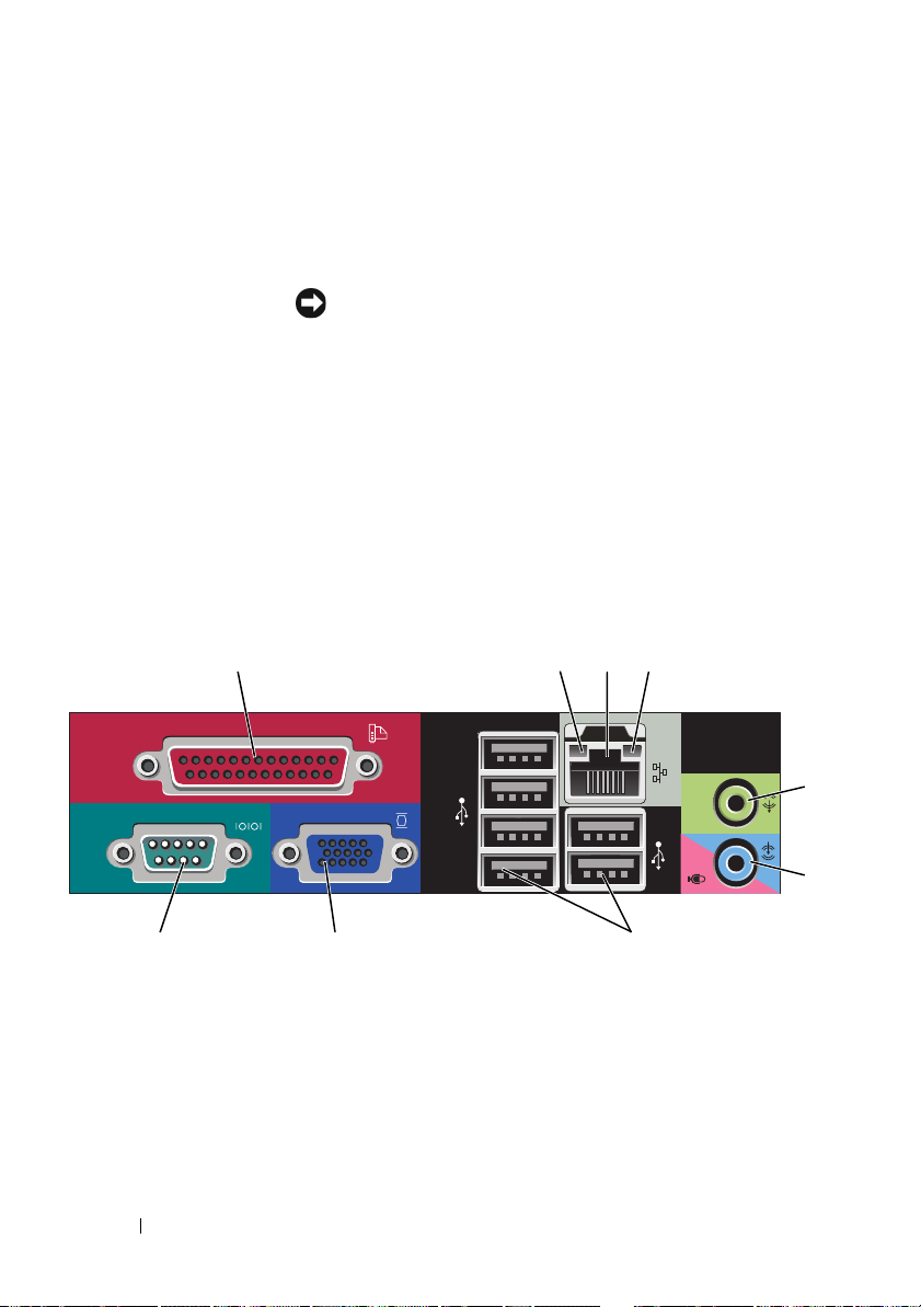
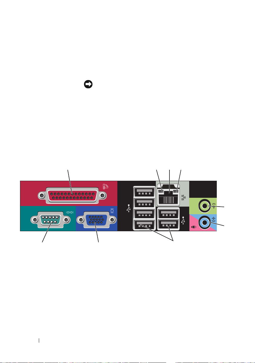
Back Panel Connectors
13
98 7
1 parallel connector Connect a parallel device, such as a printer, to the parallel
connector. If you have a USB printer, plug it into a USB
connector.
24
NOTE: The integrated parallel connector is automatically
disabled if the computer detects an installed card containing a
parallel connector configured to the same address. For more
information, see "System Setup Options" in the User’s Guide.
20 Quick Reference Guide
5
6
Page 21

2 link integrity light
3 network adapter
connector
4 network activity
light
5 line-out
connector
6 line-
in/microphone
connector
7 USB 2.0
connectors (6)
• Green — A good connection exists between a 10-Mbps
network and the computer.
• Orange — A good connection exists between a 100-Mbps
network and the computer.
• Yellow — A good connection exists between a 1-Gbps
(or 1000-Mbps) network and the computer.
• Off — The computer is not detecting a physical
connection to the network.
To attach your computer to a network or broadband device,
connect one end of a network cable to either a network jack
or your network or broadband device. Connect the other
end of the network cable to the network adapter connector
on the back panel of your computer. A click indicates that
the network cable has been securely attached.
NOTE: Do not plug a telephone cable into the network
connector.
Remote management features require use of the onboard
NIC.
It is recommended that you use Category 5 wiring and
connectors for your network. If you must use Category 3
wiring, force the network speed to 10 Mbps to ensure
reliable operation.
Flashes a yellow light when the computer is transmitting or
receiving network data. A high volume of network traffic
may make this light appear to be in a steady "on" state.
Use the green line-out connector to attach headphones and
most speakers with integrated amplifiers.
Use the blue and pink line-in/microphone connector to
attach a record/playback device such as a cassette player, CD
player, or VCR.; or a personal computer microphone for
voice or musical input into a sound or telephony program.
Use the back USB connectors for devices that typically
remain connected, such as printers and keyboards.
Quick Reference Guide 21
Page 22

8 video connector Plug the cable from your VGA-compatible monitor into the
blue connector.
NOTE: If you purchased an optional graphics card, this
connector will be covered by a cap. Connect your monitor to
the connector on the graphics card. Do not remove the cap.
NOTE: If you are using a graphics card that supports dual
monitors, use the y-cable that came with your computer.
9 serial connector Connect a serial device, such as a handheld device, to the
serial port. The default designations are COM1 for serial
connector 1 and COM2 for serial connector 2.
For more information, see "System Setup Options" in the
User’s Guide.
Removing the Computer Cover
CAUTION: Before you begin any of the procedures in this section, follow the
safety instructions located in the Product Information Guide.
CAUTION: To guard against electrical shock, always unplug your computer from
the electrical outlet before removing the computer cover.
1
Follow the procedures in "Before You Begin" on page 13.
2
Lay the computer on its side as shown in the illustration.
3
Locate the cover release latch shown in the illustration. Then, slide the
release latch back as you lift the cover.
4
Grip the sides of the computer cover and pivot the cover up using the
hinge tabs as leverage points.
5
Remove the cover from the hinge tabs and set it aside on a soft
nonabrasive surface.
CAUTION: Graphics card heat sinks can become very hot during normal
operation. Ensure that a graphics card heat sink has had sufficient time to
cool before you touch it.
22 Quick Reference Guide
Page 23
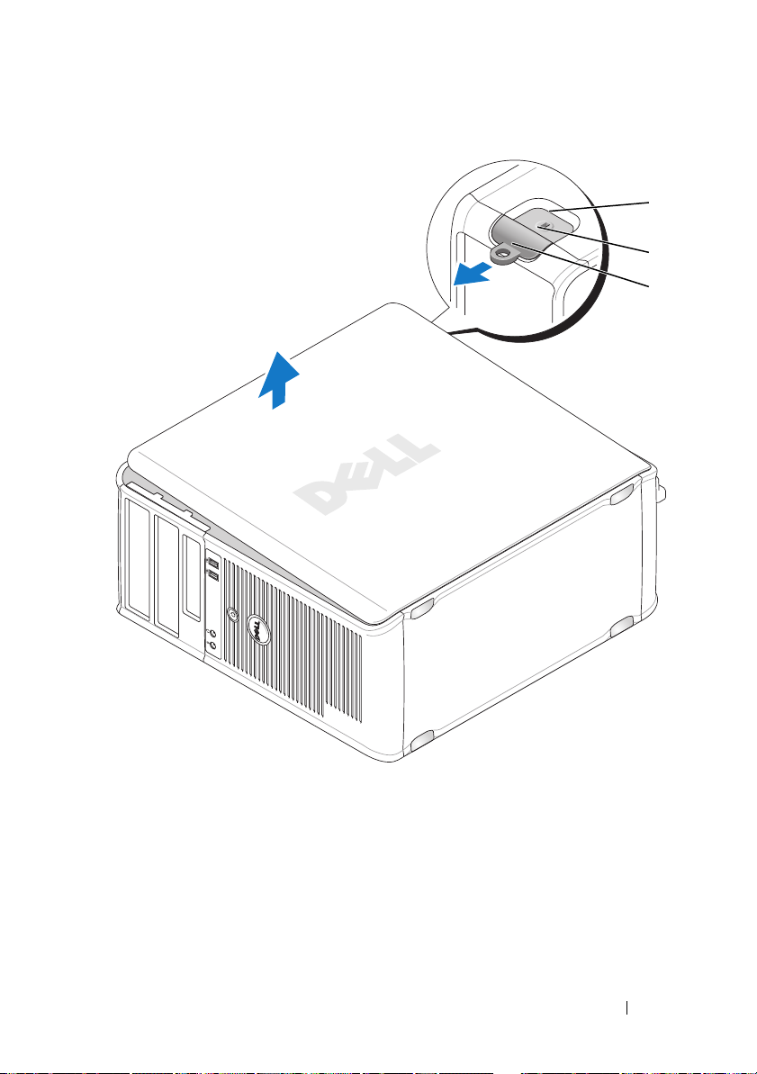
1
2
3
1 security cable slot 2 cover release latch
3 padlock ring
Quick Reference Guide 23
Page 24
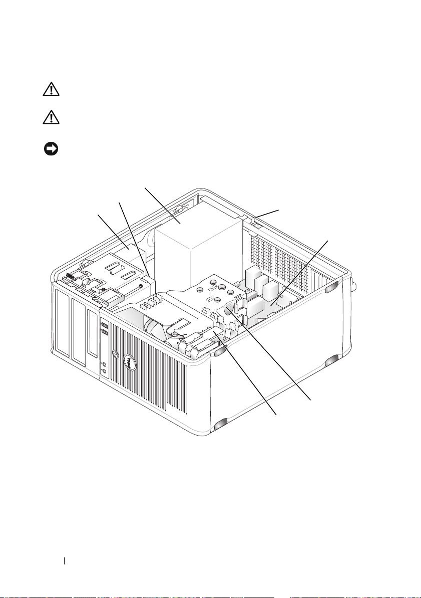
Inside Your Computer
CAUTION: Before you begin any of the procedures in this section, follow the
safety instructions located in the Product Information Guide.
CAUTION: To avoid electrical shock, always unplug your computer from the
electrical outlet before removing the computer cover.
NOTICE: Be careful when opening the computer cover to ensure that you do not
accidentally disconnect cables from the system board.
3
2
1
4
5
1 optical drive 2 disk drive
3 power supply 4 optional chassis-intrusion
5 system board 6 heat sink assembly
7 hard drive
24 Quick Reference Guide
6
7
switch
Page 25
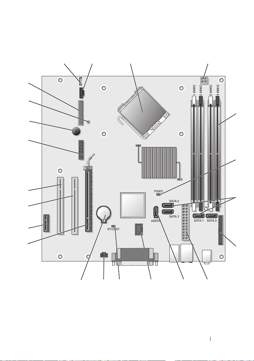
System Board Components
1
22
21
20
19
18
17
16
2
3
4
5
6
7
15
14 12
13
11
Quick Reference Guide 25
910
8
Page 26
1 speaker connector (INT_SPKR) 12 RTC reset jumper (RTCRST)
2 fan (FAN_CPU) 13 intrusion switch connector
(INTRUDER)
3 processor connector (CPU) 14 battery socket (BATTERY)
4 processor power connector
(12VPOWER)
5 memory module connectors
(DIMM_1, DIMM_2, DIMM_3,
DIMM_4)
6 password jumper (PSWD) 17 PCI connector (SLOT2)
7 SATA drive connectors (SATA0,
SATA1, SATA2, SATA3)
8 front-panel connector (FRONTPANEL) 19 serial connector (SERIAL2)
9 power connector (POWER) 20 system board speaker (BEEP)
10 external SATA connector (eSATA) 21 aux power LED (AUX_LED)
11 internal USB (INT_USB) 22 floppy connector (DSKT)
15 PCI Express x16 connector (SLOT1)
16 PCI Express x1 connector (SLOT4)
18 PCI connector (SLOT3)
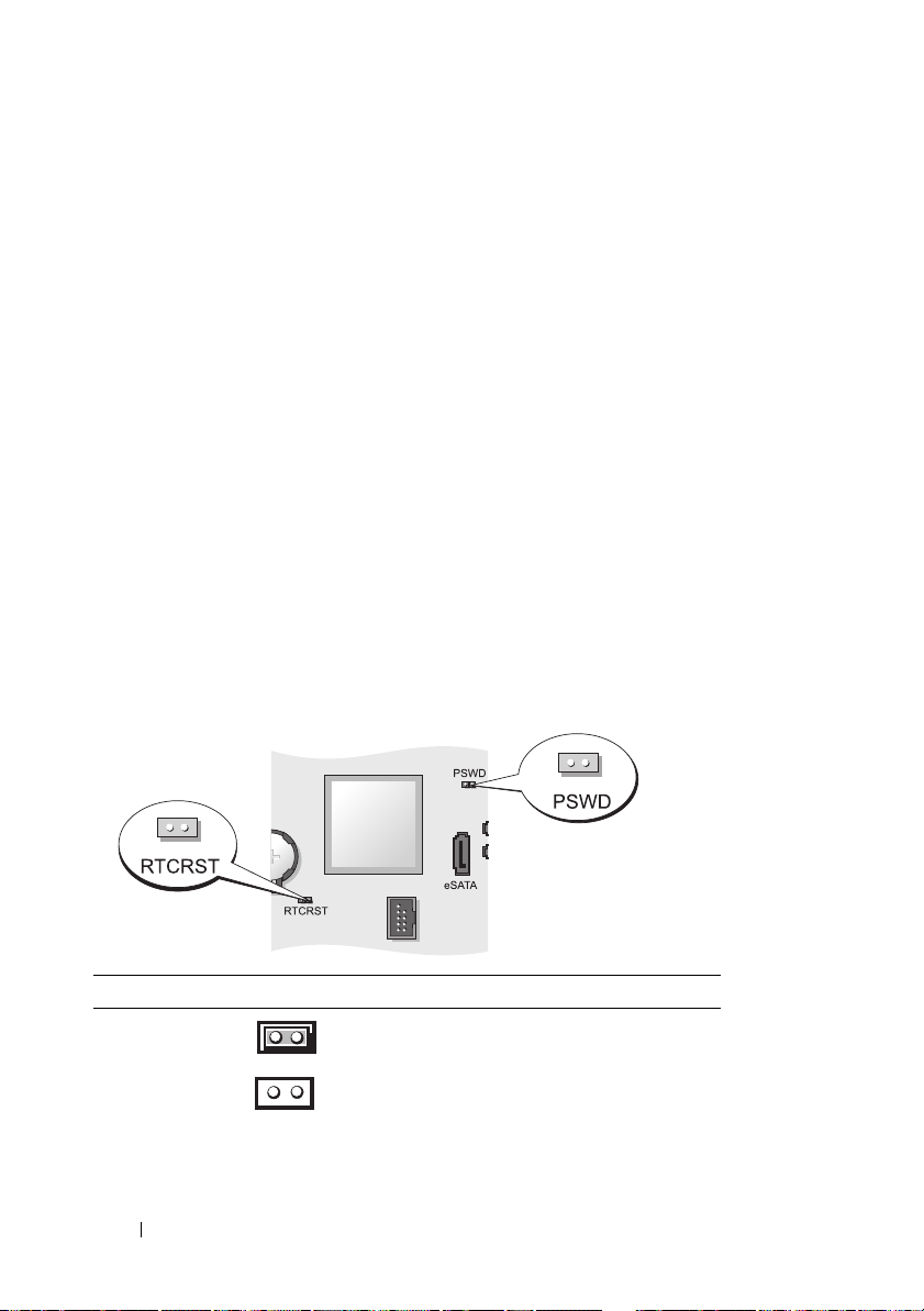
Jumper Settings
Jumper Setting Description
PSWD Password features are enabled
(default setting).
Password features are disabled.
26 Quick Reference Guide
Page 27
Jumper Setting Description
RTCRST The real-time clock has not been
reset.
jumpered unjumpered
The real-time clock is being reset
(jumpered temporarily).
Desktop Computer
System Views
Front View
1 USB 2.0
connectors (2)
2 LAN indicator
light
2
89
7
Use the front USB connectors for devices that you connect
occasionally, such as joysticks or cameras, or for bootable
USB devices (see "System Setup"
more information about booting to a USB device).
It is recommended that you use the back USB connectors
for devices that typically remain connected, such as
printers and keyboards.
This light indicates that a LAN (local area network)
connection is established.
514611 10
in the
3
User’s Guide
for
Quick Reference Guide 27
Page 28

3 power button Press this button to turn on the computer.
NOTICE: To avoid losing data, do not turn off the
computer by pressing the power button. Instead,
perform an operating system shutdown. See "Turning
Off Your Computer" in the User’s Guide for more
information.
NOTICE: If your operating system has ACPI enabled,
when you press the power button the computer will
perform an operating system shutdown.
4 Dell badge This badge can be rotated to match the orientation of your
computer. To rotate, place fingers around the outside of
the badge, press firmly, and turn the badge. You can also
rotate the badge using the slot provided near the bottom of
the badge.
5 power light The power light illuminates and blinks or remains solid to
indicate different operating states:
• No light — The computer is turned off.
• Steady green — The computer is in a normal operating
state.
• Blinking green — The computer is in a power-saving
mode.
• Blinking or solid amber — See "Power Problems" in the
User’s Guide
To exit from a power-saving mode, press the power button
or use the keyboard or the mouse if it is configured as a
wake device in the Windows Device Manager. For more
information about sleep modes and exiting from a powersaving mode, see
Vista" in the
See "Diagnostic Lights" on page 66 for a description of
light codes that can help you troubleshoot problems with
your computer.
6 diagnostic lights Use the lights to help you troubleshoot a computer
problem based on the diagnostic code. For more
information, see "Diagnostic Lights" on page 66.
7 hard drive
activity light
This light flickers when the hard drive is being accessed.
.
"Power Management for Windows XP and
User’s Guide
.
28 Quick Reference Guide
Page 29
8 headphone
connector
9 microphone
connector
10 3.5-inch drive
bay
11 5.25-inch drive
bay
Back View
Use the headphone connector to attach headphones and
most kinds of speakers.
Use the microphone connector to attach a microphone.
Can contain an optional floppy drive, second hard drive, or
optional media card reader.
Can contain an optical drive. Insert a CD or DVD
(if supported) into this drive.
1
1 card slots (3) Access connectors for any installed PCI or PCI Express
2 3 4 6
cards, PS/2 connector, eSATA connector, etc.
NOTE: The back view of the system will be different if a riser is
installed.
2 back panel
connectors
3 power connector Insert the power cable.
Plug serial, USB, and other devices into the appropriate
connectors (see "Back Panel Connectors" on page 30).
5
Quick Reference Guide 29
Page 30
4 voltage selection
switch
5 padlock ring Insert a padlock to lock the computer cover.
6 cover-release
latch
Your computer is equipped with a manual voltage selection
switch. To help avoid damaging a computer with a manual
voltage selection switch, set the switch for the voltage that
most closely matches the AC power available in your
location.
NOTICE: In Japan, the voltage selection switch must be
set to the 115-V position.
Also, ensure that your monitor and attached devices are
electrically rated to operate with the AC power available in
your location.
Allows you to open the computer cover.
Back Panel Connectors
13
98 7
1 parallel connector Connect a parallel device, such as a printer, to the parallel
connector. If you have a USB printer, plug it into a USB
connector.
24
NOTE: The integrated parallel connector is automatically
disabled if the computer detects an installed card containing a
parallel connector configured to the same address. For more
information, see "System Setup Options" in the User’s Guide.
30 Quick Reference Guide
5
6
Page 31

2 link integrity light
3 network adapter
connector
4 network activity
light
5 line-out
connector
6 line-
in/microphone
connector
7 USB 2.0
connectors (6)
• Green — A good connection exists between a 10-Mbps
network and the computer.
• Orange — A good connection exists between a 100-Mbps
network and the computer.
• Yellow — A good connection exists between a 1-Gbps
(or 1000-Mbps) network and the computer.
• Off — The computer is not detecting a physical
connection to the network.
To attach your computer to a network or broadband device,
connect one end of a network cable to either a network jack
or your network or broadband device. Connect the other
end of the network cable to the network adapter connector
on the back panel of your computer. A click indicates that
the network cable has been securely attached.
NOTE: Do not plug a telephone cable into the network
connector.
Remote management features require use of the onboard
NIC.
It is recommended that you use Category 5 wiring and
connectors for your network. If you must use Category 3
wiring, force the network speed to 10 Mbps to ensure
reliable operation.
Flashes a yellow light when the computer is transmitting or
receiving network data. A high volume of network traffic
may make this light appear to be in a steady "on" state.
Use the green line-out connector to attach headphones and
most speakers with integrated amplifiers.
Use the blue and pink line-in/microphone connector to
attach a record/playback device such as a cassette player, CD
player, or VCR; or a personal computer microphone for voice
or musical input into a sound or telephony program.
Use the back USB connectors for devices that typically
remain connected, such as printers and keyboards.
Quick Reference Guide 31
Page 32

8 video connector Plug the cable from your VGA-compatible monitor into the
blue connector.
NOTE: If you purchased an optional graphics card, this
connector will be covered by a cap. Connect your monitor to
the connector on the graphics card. Do not remove the cap.
NOTE: If you are using a graphics card that supports dual
monitors, use the y-cable that came with your computer.
9 serial connector Connect a serial device, such as a handheld device, to the
serial port. The default designations are COM1 for serial
connector 1 and COM2 for serial connector 2.
For more information, see "System Setup Options"
User’s Guide
.
in the
Removing the Computer Cover
CAUTION: Before you begin any of the procedures in this section, follow the
safety instructions in the Product Information Guide.
CAUTION: To guard against electrical shock, always unplug your computer from
the electrical outlet before removing the computer cover.
1
Follow the procedures in "Before You Begin" on page 13.
2
If you have installed a padlock through the padlock ring on the back panel,
remove the padlock.
3
Locate the cover release latch shown in the illustration. Then, slide the
release latch back as you lift the cover.
4
Grip the sides of the computer cover and pivot the cover up using the
hinge tabs as leverage points.
5
Remove the cover from the hinge tabs and set it aside on a soft
nonabrasive surface.
CAUTION: Graphics card heat sinks can become very hot during normal
operation. Ensure that a graphics card heat sink has had sufficient time to cool
before you touch it.
32 Quick Reference Guide
Page 33

1 security cable slot 2 cover release latch
3 padlock ring
1
2
3
Inside Your Computer
CAUTION: Before you begin any of the procedures in this section, follow the
safety instructions in the Product Information Guide.
CAUTION: To avoid electrical shock, always unplug your computer from the
electrical outlet before removing the computer cover.
NOTICE: Be careful when opening the computer cover to ensure that you do not
accidentally disconnect cables from the system board.
Quick Reference Guide 33
Page 34

2
1
7
1 drive bays (media card reader
or floppy drive, optical drive
and hard drive)
3 optional chassis-intrusion
switch
5 card slots 6 heat sink assembly
7 front I/O panel
2 power supply
4 system board
3
6
4
5
34 Quick Reference Guide
Page 35

System Board Components
12
22
21
20
19
18
17
16
15
3
4
5
6
7
14
91013
Quick Reference Guide 35
81112
Page 36

1 internal speaker (INT_SPKR) 12 intrusion switch connector
(INTRUDER)
2 processor connector (CPU) 13 battery socket (BATTERY)
3 processor power connector
(12VPOWER)
4 memory module connectors
(DIMM_1, DIMM_2, DIMM_3,
DIMM_4)
5 password jumper (PSWD) 16 PCI connector (SLOT3)
6 SATA connectors (SATA0, SATA1,
SATA2)
7 front-panel connector (FRONTPANEL) 18 serial connector (SERIAL2)
8 power connector (POWER) 19 system board speaker (BEEP)
9 external SATA connector (eSATA) 20 aux power LED (AUX_LED)
10 internal USB (INT_USB) 21 floppy connector (DSKT)
11 RTC reset jumper (RTCRST) 22 fan connector (FAN_CPU)
14 PCI Express x16 connector (SLOT1)
15 PCI connector (SLOT2)
17 riser connector (uses PCI-E
port/SLOT1 and PCI port/SLOT2)
Jumper Settings
Jumper Setting Description
PSWD Password features are enabled
(default setting).
Password features are disabled.
36 Quick Reference Guide
Page 37

Jumper Setting Description
RTCRST The real-time clock has not been
reset.
jumpered unjumpered
The real-time clock is being reset
(jumpered temporarily).
Small Form Factor Computer
System Views
Front View
11 10
1 USB 2.0
connectors (2)
2
1
89
Use the front USB connectors for devices that you connect
occasionally, such as joysticks or cameras, or for bootable
USB devices (see "System Setup" in the User’s Guide for
more information about booting to a USB device).
It is recommended that you use the back USB connectors
for devices that typically remain connected, such as
printers and keyboards.
7
3
4
5
6
Quick Reference Guide 37
Page 38

2 power button Press to turn on the computer.
NOTICE: To avoid losing data, do not turn off the
computer by pressing the power button. Instead,
perform an operating system shutdown. See "Turning
Off Your Computer" on page 13 for more information.
NOTICE: If your operating system has ACPI enabled,
when you press the power button the computer will
perform an operating system shutdown.
3 Dell badge Can be rotated to match the orientation of your computer.
To rotate, place fingers around the outside of the badge,
press firmly, and turn the badge. You can also rotate the
badge using the slot provided near the bottom of the
badge.
4 LAN indicator
light
5 diagnostic lights Use the lights to help you troubleshoot a computer
6 hard drive
activity light
Indicates that a LAN (local area network) connection is
established.
problem based on the diagnostic code. For more
information, see "Diagnostic Lights" on page 66.
This light flickers when the hard drive is being accessed.
38 Quick Reference Guide
Page 39

7 power light The power light illuminates and blinks or remains solid to
indicate different operating states:
• No light — The computer is turned off.
• Steady green — The computer is in a normal operating
state.
• Blinking green — The computer is in a power-saving
mode.
"Power Problems" in the
8 headphone
connector
9 microphone
connector
10 3.5-inch drive
bay
11 5.25-inch drive
bay
• Blinking or solid amber — See
User’s Guide
To exit from a power-saving mode, press the power button
or use the keyboard or the mouse if it is configured as a
wake device in the Windows Device Manager. For more
information about sleep modes and exiting from a powersaving mode, see "Power Management for Windows XP
and Vista" in the User’s Guide.
See "Dell Diagnostics" on page 61 for a description of light
codes that can help you troubleshoot problems with your
computer.
Use the headphone connector to attach headphones and
most kinds of speakers.
Use the microphone connector to attach a microphone.
Can contain an optional slimline floppy drive or optional
media card reader.
Can contain a slimline optical drive. Insert a CD or DVD
(if supported) into this drive.
.
Quick Reference Guide 39
Page 40

Back View
1 card slots (2) Access connectors for any installed PCI cards, PCI Express
cards, PS/2, eSATA, and so on.
2 back panel
connectors
3 power connector Insert the power cable.
4 voltage selection
switch
Plug serial, USB, and other devices into the appropriate
connectors (see "Back Panel Connectors" on page 41).
Your computer is equipped with a manual voltage-selection
switch. To help avoid damaging a computer with a manual
voltage selection switch, set the switch for the voltage that
most closely matches the AC power available in your
location.
51 2 3 4
6
NOTICE: In Japan, the voltage selection switch must be
set to the 115-V position.
Also, ensure that your monitor and attached devices are
electrically rated to operate with the AC power available in
your location.
5 padlock ring Insert a padlock to lock the computer cover.
6 cover release
latch
Allows you to open the computer cover.
40 Quick Reference Guide
Page 41

Back Panel Connectors
13
98 7
1 parallel connector Connect a parallel device, such as a printer, to the parallel
connector. If you have a USB printer, plug it into a USB
connector.
24
NOTE: The integrated parallel connector is automatically
disabled if the computer detects an installed card containing a
parallel connector configured to the same address. For more
information, see "System Setup Options" in the User’s Guide.
2 link integrity light
• Green — A good connection exists between a 10-Mbps
network and the computer.
• Orange — A good connection exists between a 100-Mbps
network and the computer.
• Yellow — A good connection exists between a 1-Gbps
(or 1000-Mbps) network and the computer.
• Off — The computer is not detecting a physical
connection to the network.
5
6
Quick Reference Guide 41
Page 42

3 network adapter
connector
4 network activity
light
5 line-out
connector
6 line-
in/microphone
connector
7 USB 2.0
connectors (6)
To attach your computer to a network or broadband device,
connect one end of a network cable to either a network jack
or your network or broadband device. Connect the other
end of the network cable to the network adapter connector
on the back panel of your computer. A click indicates that
the network cable has been securely attached.
NOTE: Do not plug a telephone cable into the network
connector.
Remote management features require use of the onboard
NIC.
It is recommended that you use Category 5 wiring and
connectors for your network. If you must use Category 3
wiring, force the network speed to 10 Mbps to ensure
reliable operation.
Flashes a yellow light when the computer is transmitting or
receiving network data. A high volume of network traffic
may make this light appear to be in a steady "on" state.
Use the green line-out connector (available on computers
with integrated sound) to attach headphones and most
speakers with integrated amplifiers.
Use the blue and pink line-in/microphone connector
(available on computers with integrated sound) to attach a
record/playback device such as a cassette player, CD player,
or VCR; or a personal computer microphone for voice or
musical input into a sound or telephony program.
Use the back USB connectors for devices that typically
remain connected, such as printers and keyboards.
42 Quick Reference Guide
Page 43

8 video connector Plug the cable from your VGA-compatible monitor into the
blue connector.
NOTE: If you purchased an optional graphics card, this
connector will be covered by a cap. Connect your monitor to
the connector on the graphics card. Do not remove the cap.
NOTE: If you are using a graphics card that supports dual
monitors, use the y-cable that came with your computer.
9 serial connector Connect a serial device, such as a handheld device, to the
serial port.
For more information, see "System Setup Options" in the
User’s Guide.
Removing the Computer Cover
CAUTION: Before you begin any of the procedures in this section, follow the
safety instructions in the Product Information Guide.
CAUTION: To guard against electrical shock, always unplug your computer from
the electrical outlet before removing the computer cover.
1
Follow the procedures in "Before You Begin" on page 13.
2
If you have installed a padlock through the padlock ring on the back panel,
remove the padlock.
3
Locate the cover release latch shown in the illustration. Then, slide the
release latch back as you lift the cover.
4
Grip the sides of the computer cover and pivot the cover up using the
bottom hinges as leverage points.
5
Remove the cover from the hinge tabs and set it aside on a soft
nonabrasive surface.
CAUTION: Graphics card heat sinks can become very hot during normal
operation. Ensure that a graphics card heat sink has had sufficient time to cool
before you touch it.
Quick Reference Guide 43
Page 44

1
3
1 security cable slot 2 cover release latch
3 computer cover
2
Inside Your Computer
CAUTION: Before you begin any of the procedures in this section, follow the
safety instructions in the Product Information Guide.
CAUTION: To avoid electrical shock, always unplug your computer from the
electrical outlet before removing the computer cover.
NOTICE: Be careful when opening the computer cover to ensure that you do not
accidentally disconnect cables from the system board.
44 Quick Reference Guide
Page 45

3
2
1
6
1 drive-release latch 2 optical drive
3 power supply 4 hard drive
5 system board 6 heat sink assembly
4
5
Quick Reference Guide 45
Page 46

System Board Components
12
21
20
19
18
17
16
3
4
5
6
15
14
12 10
13
46 Quick Reference Guide
7
911
8
Page 47

1 internal speaker connector
(INT_SPKR)
2 processor connector (CPU) 13 intrusion switch connector
3 processor power connector
(12VPOWER)
4 memory module connectors
(DIMM_1, DIMM_2, DIMM_3,
DIMM_4)
5 password jumper (PSWD) 16 PCI connector (SLOT2)
6 SATA connectors (SATA0, SATA1) 17 serial connector (SERIAL2)
7 front-panel connector (FRONTPANEL) 18 system board speaker (BEEP)
8 power connector (POWER) 19 aux power LED (AUX_LED)
9 fan connector (FAN_HDD) 20 floppy drive connector (DSKT)
10 eSATA connector (eSATA) 21 fan connector (FAN_CPU)
11 internal USB connector (INT_USB)
12 RTC reset jumper (RTCRST)
(INTRUDER)
14 battery socket (BATTERY)
15 PCI Express x16 connector (SLOT1)
Jumper Settings
Jumper Setting Description
PSWD Password features are enabled
(default setting).
Password features are disabled.
Quick Reference Guide 47
Page 48

Jumper Setting Description
RTCRST The real-time clock has not been
reset.
jumpered unjumpered
The real-time clock is being reset
(jumpered temporarily).
Ultra Small Form Factor Computer
System Views
NOTICE: Do not place your monitor on the computer. Use a
monitor stand.
NOTICE: When setting up your computer, secure all cables
toward the back of your work area to prevent the cables
from being pulled, tangled, or stepped on.
NOTE: If you want to orient your computer under a desk top
or on a wall surface, use the optional wall-mount bracket.
To order this bracket
Front View
1234 5
, contact Dell (see "Contacting Dell"
in the
User’s Guide
).
48 Quick Reference Guide
7896
Page 49

1 USB connectors
(2)
2 microphone
connector
3 headphone
connector
4 power light The power light illuminates and blinks or remains solid to
5 power button Press this button to turn on the computer.
Use the front USB connectors for devices that you connect
occasionally, such as joysticks or cameras, or for bootable
USB devices (see "System Setup" in the User’s Guide for
more information about booting to a USB device).
It is recommended that you use the back USB connectors for
devices that typically remain connected, such as printers and
keyboards.
Use the microphone connector to attach a microphone.
Use the headphone connector to attach headphones and
most kinds of speakers.
indicate different states:
• No light — The computer is turned off.
• Steady green — The computer is in a normal operating
state.
• Blinking green — The computer is in a power-saving mode.
• Blinking or solid yellow — See "Power Problems" in the
User’s Guide
To exit from a power-saving mode, press the power button or
use the keyboard or the mouse if it is configured as a wake
device in the Windows Device Manager. For more
information about sleep modes and exiting from a powersaving mode, see
Vista
" in the User’s Guide.
See "System Lights" on page 65 for a description of light
codes that can help you troubleshoot problems with your
computer.
.
"Power Management for Windows XP and
NOTICE: To avoid losing data, do not turn off the
computer by pressing the power button. See "Turning Off
Your Computer" on page 13 for more information
6 vents The vents help prevent your computer from overheating. To
ensure proper ventilation, do not block these cooling vents.
7 module bay Install a D-module optical drive, second hard drive, or floppy
drive in the module bay.
Quick Reference Guide 49
Page 50

8 hard drive access
light
9 vents The vents help prevent your computer from overheating. To
The hard drive access light is on when the computer reads
data from or writes data to the hard drive. The light might
also be on when devices such as your CD player are
operating.
ensure proper ventilation, do not block these cooling vents.
Side View
1
1 vents The vents located on each side of the computer help prevent your
computer from overheating. To ensure proper ventilation, do not
block these cooling vents.
2 mounting
holes
For mounting optional stand.
2
50 Quick Reference Guide
Page 51

Back View
231
5
1 diagnostic lights See "Diagnostic Lights" on page 66 for a description
2 computer cover release
knob
3 back panel connectors See "Back Panel Connectors" on page 52 for a
4 power connector Insert the AC power adapter plug.
5 vents The vents help prevent your computer from
4
of light codes that can help you troubleshoot
problems with your computer.
Rotate this knob in a clockwise direction to remove
the cover.
description of the connectors for your computer.
overheating. To ensure proper ventilation, do not
block these cooling vents.
Quick Reference Guide 51
Page 52

Back Panel Connectors
2134
5
6
10 7811
1 parallel
connector
2 link integrity
light
3 network adapter To attach your computer to a network or broadband device,
9
Connect a parallel device, such as a printer, to the parallel
connector. If you have a USB printer, plug it into a USB
connector.
• Green — A good connection exists between a 10-Mbps
network and the computer.
• Orange — A good connection exists between a 100-Mbps
network and the computer.
• Yellow — A good connection exists between a 1000-Mbps
(1-Gbps) network and the computer.
• Off — The computer is not detecting a physical
connection to the network or the network controller is
turned off in system setup.
connect one end of a network cable to either a network jack
or your network or broadband device. Connect the other
end of the network cable to the network adapter connector
on the back panel of your computer. A click indicates that
the network cable has been securely attached.
NOTE: Do not plug a telephone cable into the network
connector.
It is recommended that you use Category 5 wiring and
connectors for your network. If you must use Category 3
wiring, force the network speed to 10 Mbps to ensure
reliable operation.
52 Quick Reference Guide
Page 53

4 network activity
light
5 line-out
connector
6 line-
in/microphone
connector
7 USB connectors
(5)
8 serial connector Connect a serial device, such as a handheld device, to the
9 video connector If you have a DVI-compatible monitor, plug the cable from
10 power connector Insert the AC power adapter plug.
11 diagnostic lights See "Diagnostic Lights" on page 66 for a description of light
The amber light flashes when the computer is transmitting
or receiving network data. A high volume of network traffic
may make this light appear to be in a steady "on" state.
Use the green line-out connector to attach an amplified
speaker set.
Use the blue and pink line-in/microphone connector to
attach a record/playback device such as a cassette player,
CD player, or VCR.; or a personal computer microphone for
voice or musical input into a sound or telephony program.
Use the back USB connectors for devices that typically
remain connected, such as printers and keyboards.
serial connector.
your monitor into the white DVI video connector on the
back panel.
If you have a VGA monitor, see "Connecting a VGA
Monitor" on page 53.
codes that can help you troubleshoot problems with your
computer.
Connecting a VGA Monitor
If you have a VGA monitor, plug the adapter cable into the white DVI video
connector on the back panel of your computer, and connect the monitor cable
to the VGA connector on the adapter.
Quick Reference Guide 53
Page 54

1 cable adapter 2 VGA connector
3 monitor cable
Connecting Two Monitors
1
1
1 cable adapter
Use the cable adapter to connect a VGA monitor and a DVI monitor to the
DVI-I connector on the back panel.
54 Quick Reference Guide
Page 55

When you connect two monitors, the video driver will detect this connection
and activate the multimonitor functionality.
Removing the Computer Cover
CAUTION: Before you begin any of the procedures in this section, follow the
safety instructions in the Product Information Guide.
NOTICE: To prevent static damage to components inside your computer, discharge
static electricity from your body before you touch any of your computer’s electronic
components. You can do so by touching an unpainted metal surface on the
computer chassis.
1
Follow the procedures in "Before You Begin" on page 13.
2
Remove the computer cover (see "Removing the Computer Cover" on
page 55).
NOTICE: Before touching anything inside your computer, ground yourself by
touching an unpainted metal surface. While you work, periodically touch an
unpainted metal surface to dissipate any static electricity that could harm internal
components.
3
If applicable, remove the cable cover, (see "Cable Cover (Optional)" on
page 57).
4
Remove the computer cover:
a
Rotate the cover release knob in a clockwise direction, as shown in the
illustration.
b
Slide the computer cover forward by 1 cm (½ inch), or until it stops,
and then raise the cover.
CAUTION: Graphics card heat sinks can become very hot during normal
operation. Ensure that a graphics card heat sink has had sufficient time to cool
before you touch it.
Quick Reference Guide 55
Page 56

1 release knob
Inside Your Computer
CAUTION: Before you begin any of the procedures in this section, follow the
safety instructions in the Product Information Guide.
CAUTION: To avoid electrical shock, always unplug your computer from the AC
power adapter before removing the cover.
NOTICE: To prevent static damage to components inside your computer, discharge
static electricity from your body before you touch any of your computer’s electronic
components. You can do so by touching an unpainted metal surface on the
computer chassis.
56 Quick Reference Guide
Page 57

1
2
6
5
1 fan shroud/heat sink assembly 2 speaker (optional)
3 memory modules (2) 4 hard drive
5 security cable slot 6 chassis intrusion switch
4
Cable Cover (Optional)
Attaching the Cable Cover
1
Ensure that all external device cables are threaded through the hole in the
cable cover.
2
Connect all device cables to the connectors on the back of the computer.
3
Hold the bottom of the cable cover so as to align the tabs with the slots on
the computer’s back panel.
4
Insert the tabs into the slots and slide the cover to align the ends of the
cover with the ends of the chassis (see the illustration) until the cable
cover is securely positioned.
5
Install a security device in the security cable slot (optional).
3
Quick Reference Guide 57
Page 58

1
2
1 cable cover 2 security cable slot
Removing the Cable Cover
1
If a security device is installed in the security cable slot, remove the device.
1
1 release button
2
Slide the release button, grasp the cable cover, and slide the cover sideways
as shown until it stops, and then lift the cable cover up and away.
58 Quick Reference Guide
Page 59

System Board Components
1234
14
13
12
5
6
7
8
9
10
11
Quick Reference Guide 59
Page 60

1 fan connector (FAN_FRONT) 8 password jumper (PSWD)
2 internal speaker connector
(INT_SPKR)
3 system board speaker (BEEP) 10 clear CMOS jumper (RTCRST)
4 channel B memory connector
(DIMM_2)
5 channel A memory connector
(DIMM_1)
6 SATA data cable connector
(SATA0)
7 battery (BATT) 14 processor (CPU)
9 hard drive fan connector (FAN_HDD)
11 hard drive power connector (SATA_PWR)
12 fan connector (FAN_REAR)
13 intrusion switch connector (INTRUDER)
Jumper Settings
Jumper Setting Description
PSWD Password features are enabled
(default setting).
Password features are disabled.
60 Quick Reference Guide
Page 61

Jumper Setting Description
RTCRST The real-time clock has not been
reset.
jumpered unjumpered
The real-time clock is being reset
(jumpered temporarily).
Solving Problems
Dell provides a number of tools to help you if your computer does not
perform as expected. For the latest troubleshooting information available for
your computer, see the Dell Support website at support.dell.com.
If computer problems occur that require help from Dell, write a detailed
description of the error, beep codes, or diagnostics light patterns, record your
Express Service Code and Service Tag below, and then contact Dell from the
same location as your computer. For information on contacting Dell, see your
online User’s Guide.
For an example of the Express Service Code and Service Tag, see "Finding
Information" in your computer User’s Guide.
Express Service Code:___________________________
Service Tag:___________________________
Dell Diagnostics
CAUTION: Before you begin any of the procedures in this section, follow the
safety instructions located in the Product Information Guide.
When to Use the Dell Diagnostics
If you experience a problem with your computer, perform the checks in this
section and run the Dell Diagnostics before you contact Dell for technical
assistance.
It is recommended that you print these procedures before you begin.
NOTICE: The Dell Diagnostics works only on Dell™ computers.
Enter system setup (see "Entering System Setup" in the User’s Guide), review
your computer’s configuration information, and ensure that the device you
want to test displays in system setup and is active.
Quick Reference Guide 61
Page 62

Start the Dell Diagnostics from either your hard drive or from the Drivers and
Utilities media (an optional CD). See "Starting the Dell Diagnostics From
Your Hard Drive" on page 62 or "Starting the Dell Diagnostics From the
Drivers and Utilities CD (Optional)" on page 63 for more information.
Starting the Dell Diagnostics From Your Hard Drive
The Dell Diagnostics is located on a hidden diagnostic utility partition on
your hard drive.
NOTE: If your computer cannot display a screen image, contact Dell.
1
Shut down the computer. Turn on (or restart) your computer.
2
If the computer is connected to a docking device (docked), undock it. See
the documentation that came with your docking device for instructions.
3
Connect the computer to an electrical outlet.
4
Turn on the computer. When the DELL™ logo appears, press <F12>
immediately.
NOTE: If you see a message stating that no diagnostics utility partition has been
found, run the Dell Diagnostics from your optional Drivers and Utilities CD. See
"Using the Drivers and Utilities Media" on page 78 for more information about the
optional Drivers and Utilities CD.
If you wait too long and the operating system logo appears, continue to
wait until you see the Microsoft
®
Windows® desktop. Then shut down
your computer and try again.
5
When the boot device list appears, highlight
Partition
6
Press any key to choose a diagnostic option on your hard drive. The
and press <Enter>.
DiagnosticsBoot to Utility
resulting menu displays:
• Test Memory - this takes you to the MPMemory Diagnostic
• Test System - takes you to the Dell Diagnostic Utility
• Exit - exits Diagnostics
7
Select
Test System
8
When the Dell Diagnostics
.
Main Menu
appears, select the test you want
to run (see "Dell Diagnostics Main Menu" on page 63).
62 Quick Reference Guide
Page 63

Starting the Dell Diagnostics From the Drivers and Utilities CD (Optional)
1
Insert the
2
Shut down and restart the computer.
Drivers and Utilities
CD (optional).
When the DELL logo appears, press <F12> immediately.
If you wait too long and the Windows logo appears, continue to wait until
you see the Windows desktop. Then shut down your computer and try
again.
NOTE: The next steps change the boot sequence for one time only. On the next
start-up, the computer boots according to the devices specified in system setup.
3
When the boot device list appears, highlight
SATA CD-ROM Device
press <Enter>.
4
Select the
5
Select the
6
Ty p e 1 to start the
7
Ty p e 2 to start the Dell Diagnostics.
8
Select
SATA CD-ROM Device
Boot from CD-ROM
option from the CD boot menu.
option from the menu that appears.
Drivers and Utilities
Run the 32 Bit Dell Diagnostics
CD menu.
from the numbered list. If
multiple versions are listed, select the version appropriate for your
computer.
9
When the Dell Diagnostics
Main Menu
appears, select the test you want
to run (see "Dell Diagnostics Main Menu" on page 63).
and
Dell Diagnostics Main Menu
1
After the Dell Diagnostics loads and the
Main Menu
screen appears, click
the button for the option you want.
Option Function
Express Test Performs a quick test of devices. This test typically takes
10 to 20 minutes and requires no interaction on your part.
Run Express Test first to increase the possibility of tracing
the problem quickly.
Extended Test Performs a thorough check of devices. This test typically
takes an hour or more and requires you to answer
questions periodically.
Quick Reference Guide 63
Page 64

Option Function
Custom Test Tests a specific device. You can customize the tests you
want to run.
Symptom Tree Lists the most common symptoms encountered and
allows you to select a test based on the symptom of the
problem you are having.
2
If a problem is encountered during a test, a message appears with an error
code and a description of the problem. Write down the error code and
problem description and follow the instructions on the screen.
If you cannot resolve the error condition, contact Dell (see "Contacting
Dell"
in the
User’s Guide
NOTE: The Service Tag for your computer is located at the top of each test screen.
If you contact Dell, technical support will ask for your Service Tag. Your computer’s
Service Tag is listed in the System Info option in system setup. See "System Setup" in
the User’s Guide for more information.
3
If you run a test from the
).
Custom Test
or
Symptom Tree
option, click the
applicable tab described in the following table for more information.
Tab Function
Results Displays the results of the test and any error conditions
encountered.
Errors Displays error conditions encountered, error codes, and the
problem description.
Help Describes the test and may indicate requirements for running
the test.
Configuration Displays your hardware configuration for the selected device.
The Dell Diagnostics obtains configuration information for all
devices from system setup, memory, and various internal tests,
and it displays the information in the device list in the left pane
of the screen. The device list may not display the names of all
the components installed on your computer or all devices
attached to your computer.
Parameters Allows you to customize the test by changing the test settings.
64 Quick Reference Guide
Page 65

4
When the tests are completed, if you are running the Dell Diagnostics
from the
5
When the tests are complete, close Close the test screen to return to the
Main Menu
close the
Drivers and Utilities CD
, remove the CD.
screen. To exit the Dell Diagnostics and restart the computer,
Main Menu
screen.
System Lights
Your power button light and hard drive light may indicate a computer
problem.
Power Light Problem Description Suggested Resolution
Solid green Power is on, and the computer is
operating normally. On the
desktop computer, a solid green
light indicates a network
connection.
Blinking green The computer is in a power-
saving mode.
Blinks green
several times and
then turns off
Solid yellow The Dell Diagnostics is running
Blinking yellow A power supply or system board
A configuration error exists. Check the diagnostic lights to
a test, or a device on the system
board may be faulty or
incorrectly installed.
failure has occurred.
No corrective action is required.
Press the power button, move
the mouse, or press a key on the
keyboard to wake the computer.
see if the specific problem is
identified (see "Diagnostic
Lights" on page 66).
If the Dell Diagnostics is
running, allow the testing to
complete.
If the computer does not boot,
contact Dell for technical
assistance (see "Contacting
in the
Dell"
See "Power Problems" in the
User’s Guide.
User’s Guide
).
Quick Reference Guide 65
Page 66

Power Light Problem Description Suggested Resolution
Solid green and a
beep code during
POST
Solid green
power light and
no beep code
and no video
during POST
Solid green
power light and
no beep code but
the computer
locks up during
POST
A problem was detected while
the BIOS was executing.
The monitor or the graphics
card may be faulty or incorrectly
installed.
An integrated system board
device may be faulty.
See "Beep Codes" on page 70 for
instructions on diagnosing the
beep code. Also, check the
diagnostic lights to see if the
specific problem is identified
(see "Diagnostic Lights" on
page 66).
Check the diagnostic lights to
see if the specific problem is
identified (see "Diagnostic
Lights" on page 66).
See "Video and Monitor
Problems" in the User’s Guide.
Check the diagnostic lights to
see if the specific problem is
identified (see "Diagnostic
Lights" on page 66). If the
problem is not identified,
contact Dell for technical
assistance (see "Contacting
Dell" in the User’s Guide).
Diagnostic Lights
CAUTION: Before you begin any of the procedures in this section, follow the
safety instructions in the Product Information Guide.
To help troubleshoot a problem, your computer has four lights labeled 1, 2, 3,
and 4 on the front panel. When the computer starts normally, the lights flash
before turning off. If the computer malfunctions, the sequence of the lights
help to identify the problem.
NOTE: After the computer completes POST, all four lights turn off before booting to
the operating system.
66 Quick Reference Guide
Page 67

Power Light Problem Description Suggested Resolution
The computer is in a normal off
condition or a possible pre-BIOS
failure has occurred.
The diagnostic lights are not lit
after the system successfully
boots to the operating system.
A possible processor failure has
occurred.
Memory modules are detected,
but a memory failure has
occurred.
• Plug the computer into a
working electrical outlet (see
"Power Problems" in the
).
Guide
• If the problem persists,
contact Dell (see
in the
Dell"
• Reseat the processor (see
Processor information for your
system).
• If the problem persists,
contact Dell (see
Dell" in the User’s Guide
• If two or more memory
modules are installed, remove
the modules (see "Removing
Memory" in the
then reinstall one module (see
"Installing Memory" in the
User’s Guide
computer. If the computer
starts normally, continue to
install additional memory
modules (one at a time) until
you have identified a faulty
module or reinstalled all
modules without error.
• If available, install working
memory of the same type into
your computer (see "Installing
Memory" in the
• If the problem persists,
contact Dell (see
Dell" in the User’s Guide
User’s Guide
User’s Guide
) and restart the
User’s Guide
User’s
"Contacting
).
"Contacting
).
),
).
"Contacting
).
Quick Reference Guide 67
Page 68

Power Light Problem Description Suggested Resolution
A possible graphics card failure
has occurred.
A possible floppy drive or hard
drive failure has occurred.
• Reseat any installed graphics
cards (see the "Cards"
information for your system).
• If available, install a working
graphics card into your
computer.
• If the problem persists,
contact Dell (see
Dell" in the User’s Guide
Reseat all power and data cables.
"Contacting
).
A possible USB failure has
occurred.
No memory modules are
detected.
Reinstall all USB devices and
check all cable connections.
• If two or more memory
modules are installed, remove
the modules (see "Removing
Memory" in the
then reinstall one module (see
"Installing Memory" in the
User’s Guide
computer. If the computer
starts normally, continue to
install additional memory
modules (one at a time) until
you have identified a faulty
module or reinstalled all
modules without error.
• If available, install working
memory of the same type into
your computer (see "Installing
Memory" in the
• If the problem persists,
contact Dell (see
Dell"
in the
User’s Guide
) and restart the
User’s Guide
"Contacting
User’s Guide
).
),
).
68 Quick Reference Guide
Page 69

Power Light Problem Description Suggested Resolution
Memory modules are detected,
but a memory configuration or
compatibility error has occurred.
• Ensure that no special
requirements for memory
module/connector placement
exist (see "Memory" in the
User’s Guide
).
• Ensure that the memory you
are using is supported by your
computer (see the
specifications for your system).
• If the problem persists,
contact Dell (see
in the
User’s Guide
A possible expansion card failure
has occurred.
Dell"
1
Determine if a conflict exists
by removing an expansion card
(not a graphics card) and
restarting the computer (see
the "Cards" section for your
system).
2
If the problem persists,
reinstall the card you removed,
then remove a different card
and restart the computer.
3
Repeat this process for each
expansion card installed. If the
computer starts normally,
troubleshoot the last card
removed from the computer
for resource conflicts (see
"Resolving Software and
Hardware Incompatibilities"
on page 72).
4
If the problem persists,
contact Dell (see
Dell" in the User’s Guide
"Contacting
).
"Contacting
).
Quick Reference Guide 69
Page 70

Power Light Problem Description Suggested Resolution
Another failure has occurred.
• Ensure that all hard drive and
optical drive cables are
properly connected to the
system board (see "System
Board Components" for your
system).
• If there is an error message on
the screen identifying a
problem with a device (such as
the floppy drive or hard drive),
check the device to make sure
it is functioning properly.
• If the operating system is
attempting to boot from a
device (such as the floppy
drive or optical drive), check
system setup (see "System
in the
User’s Guide
User’s Guide
Setup" in the
ensure the boot sequence is
correct for the devices
installed on your computer.
• If the problem persists,
contact Dell (see
Dell"
) to
"Contacting
).
Beep Codes
Your computer might emit a series of beeps during start-up if the monitor
cannot display errors or problems. This series of beeps, called a beep code,
identifies a problem. For example, beep code 1-3-1 (one possible beep code)
consists of one beep, a burst of three beeps, and then one beep. This beep
code tells you that the computer encountered a memory problem.
Reseating the memory modules may correct the following beep code errors. If
the problem persists, contact Dell (see "Contacting Dell"
for instructions on obtaining technical assistance.
70 Quick Reference Guide
in the
User’s Guide
)
Page 71

Code Cause
1-3-1 through
2-4-4
4-3-1 Memory failure above address 0FFFFh
Memory not being properly identified or used
If you experience any of the following beep code errors, see "Contacting Dell"
in the
User’s Guide
Code Cause
1-1-2 Microprocessor register failure
1-1-3 NVRAM read/write failure
1-1-4 ROM BIOS checksum failure
1-2-1 Programmable interval timer failure
1-2-2 DMA initialization failure
1-2-3 DMA page register read/write failure
1-3 Video Memory Test failure
1-3-1 through
2-4-4
3-1-1 Slave DMA register failure
3-1-2 Master DMA register failure
3-1-3 Master interrupt mask register failure
3-1-4 Slave interrupt mask register failure
3-2-2 Interrupt vector loading failure
3-2-4 Keyboard Controller Test failure
3-3-1 NVRAM power loss
3-3-2 Invalid NVRAM configuration
3-3-4 Video Memory Test failure
3-4-1 Screen initialization failure
3-4-2 Screen retrace failure
3-4-3 Search for video ROM failure
for instructions on obtaining technical assistance.
Memory not being properly identified or used
Quick Reference Guide 71
Page 72

Code Cause
4-2-1 No timer tick
4-2-2 Shutdown failure
4-2-3 Gate A20 failure
4-2-4 Unexpected interrupt in protected mode
4-3-1 Memory failure above address 0FFFFh
4-3-3 Timer-chip counter 2 failure
4-3-4 Time-of-day clock stopped
4-4-1 Serial or parallel port test failure
4-4-2 Failure to decompress code to shadowed memory
4-4-3 Math-coprocessor test failure
4-4-4 Cache test failure
Resolving Software and Hardware Incompatibilities
If a device is either not detected during the operating system setup or is
detected but incorrectly configured, you can use the Hardware
Troubleshooter to resolve the incompatibility.
To start the Hardware Troubleshooter:
Windows XP:
1
Click
Start→
2
Ty p e
hardware troubleshooter
<Enter> to start the search.
3
In the
4
In the
the problem and click
Windows Vista:
1
Click the Windows Vista start button , and click
2
Ty p e
hardware troubleshooter
<Enter> to start the search.
3
In the search results, select the option that best describes the problem and
follow the remaining troubleshooting steps.
Help and Support
Fix a Problem
section, click
Hardware Troubleshooter
Next
to follow the remaining troubleshooting steps.
.
in the search field and press
Hardware Troubleshooter
.
list, select the option that best describes
Help and Support.
in the search field and press
72 Quick Reference Guide
Page 73

Restoring Your Operating System
You can restore your operating system in the following ways:
• System Restore returns your computer to an earlier operating state without
affecting data files. Use System Restore as the first solution for restoring
your operating system and preserving data files.
• Dell PC Restore by Symantec (available in Windows XP) and Dell Factory
Image Restore (available in Windows Vista) returns your hard drive to the
operating state it was in when you purchased the computer. Both
permanently delete all data on the hard drive and remove any programs
installed after you received the computer. Use Dell PC Restore or Dell
Factory Image Restore only if System Restore did not resolve your
operating system problem.
• If you received an
it to restore your operating system. However, using the
disc also deletes all data on the hard drive. Use the disc
Operating System
disc with your computer, you can use
Operating System
only
if System
Restore did not resolve your operating system problem.
Using Microsoft Windows System Restore
The Windows operating systems provide a System Restore option which
allows you to return your computer to an earlier operating state (without
affecting data files) if changes to the hardware, software, or other system
settings have left the computer in an undesirable operating state. Any
changes that System Restore makes to your computer are completely
reversible.
NOTICE: Make regular backups of your data files. System Restore does not
monitor your data files or recover them.
NOTE: The procedures in this document were written for the Windows default
view, so they may not apply if you set your Dell™ computer to the Windows Classic
view.
Quick Reference Guide 73
Page 74

Starting System Restore
Windows XP:
NOTICE: Before you restore the computer to an earlier operating state, save and
close any open files and exit any open programs. Do not alter, open, or delete any
files or programs until the system restoration is complete.
1
Click
Restore
2
Click either
point
3
Click
Start→
.
Next
All Programs→ Accessories→ System Tools→
.
Restore my computer to an earlier time
and follow the remaining on-screen prompts.
System
or
Create a restore
Windows Vista:
1
Click
Start
.
2
In the Start Search box, type
NOTE: The User Account Control window may appear. If you are an
administrator on the computer, click Continue; otherwise, contact your
administrator to continue the desired action.
3
Click
Next
and follow the remaining prompts on the screen.
System Restore
and press <Enter>.
In the event that System Restore did not resolve the issue, you may undo the
last system restore.
Undoing the Last System Restore
NOTICE: Before you undo the last system restore, save and close all open files and
exit any open programs. Do not alter, open, or delete any files or programs until the
system restoration is complete.
Windows XP:
1
Click
2
Start→
Restore
Click
Undo my last restoration
All Programs→ Accessories→ System Tools→
.
and click
Next
System
.
Windows Vista:
Click
Start
1
2
In the Start Search box, type
3
Click
Undo my last restoration
.
System Restore
and click
Next
and press <Enter>.
.
74 Quick Reference Guide
Page 75

Enabling System Restore
NOTE: Windows Vista does not disable System Restore; regardless of low disk
space. Therefore, the steps below apply only to Windows XP.
If you reinstall Windows XP with less than 200 MB of free hard-disk space
available, System Restore is automatically disabled.
To see if System Restore is enabled:
1
Click
2
Click the
Start→
Control Panel→ Performance and Maintenance→ System
System Restore
tab and ensure that
Turn off System Restore
is
unchecked.
Using Dell™ PC Restore and Dell Factory Image Restore
NOTICE: Using Dell PC Restore or Dell Factory Image Restore permanently deletes
all data on the hard drive and removes any programs or drivers installed after you
received your computer. If possible, back up the data before using these options.
Use PC Restore or Dell Factory Image Restore only if System Restore did not resolve
your operating system problem.
NOTE: Dell PC Restore by Symantec and Dell Factory Image Restore may not be
available in certain countries or on certain computers.
Use Dell PC Restore (Windows XP) or Dell Factory Image Restore (Windows
Vista) only as the last method to restore your operating system. These options
restore your hard drive to the operating state it was in when you purchased
the computer. Any programs or files added since you received your
computer—including data files—are permanently deleted from the hard
drive. Data files include documents, spreadsheets, e-mail messages, digital
photos, music files, and so on. If possible, back up all data before using PC
Restore or Factory Image Restore.
.
Windows XP: Dell PC Restore
Using PC Restore:
Turn on the computer.
1
During the boot process, a blue bar with
of the screen.
www.dell.com
Quick Reference Guide 75
appears at the top
Page 76

2
Immediately upon seeing the blue bar, press <Ctrl><F11>.
If you do not press <Ctrl><F11> in time, let the computer finish
starting, and then restart the computer again.
NOTICE: If you do not want to proceed with PC Restore, click Reboot.
3
Click
Restore
and click
Confirm
.
The restore process takes approximately 6 to 10 minutes to complete.
4
When prompted, click
NOTE: Do not manually shut down the computer. Click Finish and let the computer
completely reboot.
5
When prompted, click
Finish
to reboot the computer.
Yes
.
The computer restarts. Because the computer is restored to its original
operating state, the screens that appear, such as the End User License
Agreement, are the same ones that appeared the first time the computer
was turned on.
6
Click
Next
.
The
System Restore
7
After the computer restarts, click OK.
screen appears and the computer restarts.
Removing PC Restore:
NOTICE: Removing Dell PC Restore from the hard drive permanently deletes the PC
Restore utility from your computer. After you have removed Dell PC Restore, you will
not be able to use it to restore your computer operating system.
Dell PC Restore enables you to restore your hard drive to the operating state
it was in when you purchased your computer. It is recommended that you do
not remove PC Restore from your computer, even to gain additional hard
drive space. If you remove PC Restore from the hard drive, you cannot ever
recall it, and you will never be able to use PC Restore to return your computer
operating system to its original state.
1
Log on to the computer as a local administrator.
2
In Microsoft Windows Explorer, go to
c:\dell\utilities\DSR
.
76 Quick Reference Guide
Page 77

3
Double-click the filename
NOTE: If you do not log on as a local administrator, a message appears
stating that you that you must log on as administrator. Click Quit, and then log
on as a local administrator.
NOTE: If the partition for PC Restore does not exist on your computer hard
drive, a message appears stating that the partition was not found. Click Quit;
there is no partition to delete.
4
Click OK to remove the PC Restore partition on the hard drive.
5
Click
Yes
when a confirmation message appears.
DSRIRRemv2.exe
.
The PC Restore partition is deleted and the newly available disk space is
added to the free space allocation on the hard drive.
6
Right-click
Local Disk (C)
in Windows Explorer, click
Properties
verify that the additional disk space is available as indicated by the
increased value for
7
Click
Finish
Free Space
to close the
.
PC Restore Removal
window and restart the
computer.
Windows Vista: Dell Factory Image Restore
1
Turn on the computer. When the Dell logo appears, press <F8> several
times to access the Vista Advanced Boot Options Window.
2
Select
Repair Your Computer
.
The System Recovery Options window appears.
, and
3
Select a keyboard layout and click
4
To access the recovery options, log on as a local user. To access the
command prompt, type
click
OK
.
5
Click
Dell Factory Image Restore
NOTE: Depending upon your configuration, you may need to select Dell
Factory Tools, then Dell Factory Image Restore.
administrator
Next
.
.
in the User name field, then
The Dell Factory Image Restore welcome screen appears.
Quick Reference Guide 77
Page 78

6
Click
Next.
The Confirm Data Deletion screen appears.
NOTICE: If you do not want to proceed with Factory Image Restore, click Cancel.
7
Click the checkbox to confirm that you want to continue reformatting the
hard drive and restoring the system software to the factory condition, then
click
Next
.
The restore process begins and may take five or more minutes to complete.
A message appears when the operating system and factory-installed
applications have been restored to factory condition.
8
Click
Finish
to reboot the system.
Using the Drivers and Utilities Media
NOTICE: The Drivers and Utilities media may contain drivers for operating systems
that are not on your computer. Ensure that you are installing software appropriate
for your operating system.
Many drivers, such as the keyboard driver, come with your Microsoft
Windows operating system. You may need to install drivers if you:
• Upgrade your operating system.
• Reinstall your operating system.
• Connect or install a new device.
Identifying Drivers
If you experience a problem with any device, identify whether the driver is the
source of your problem and, if necessary, update the driver.
®
Microsoft
1
2
3
Windows® XP
Click
Start→
Under
Pick a Category
System
.
In the
System Properties
Manager
.
Control Panel
, click
window, click the
.
Performance and Maintenance
Hardware
tab, and click
, and click
Device
78 Quick Reference Guide
Page 79

Microsoft Windows Vista™
1
Click the Windows Vista start button , and right-click
2
Click
Properties→ Device Manager
NOTE: The User Account Control window may appear. If you are an
administrator on the computer, click Continue; otherwise, contact your
administrator to continue.
.
Computer
.
Scroll down the list to see if any device has an exclamation point (a yellow
circle with a [!]) on the device icon.
If an exclamation point is next to the device name, you may need to reinstall
the driver or install a new driver (see "Reinstalling Drivers and Utilities" on
page 79).
Reinstalling Drivers and Utilities
NOTICE: The Dell Support website at support.dell.com and your Drivers and
Utilities media provide approved drivers for Dell™ computers. If you install drivers
obtained from other sources, your computer might not work correctly.
Using Windows Device Driver Rollback
If a problem occurs on your computer after you install or update a driver, use
Windows Device Driver Rollback to replace the driver with the previously
installed version.
Windows XP:
1
Click
Start→
2
Right-click the device for which the new driver was installed and click
Properties
3
Click the
Windows Vista:
1
Click the Windows Vista start button , and right-click
2
Click
Properties→ Device Manager
My Computer→ Properties→ Hardware→
.
Drivers
tab→
Roll Back Driver
.
.
Device Manager
Computer
.
.
NOTE: The User Account Control window may appear. If you are an
administrator on the computer, click Continue; otherwise, contact your
administrator to enter the Device Manager.
Quick Reference Guide 79
Page 80

3
Right-click the device for which the new driver was installed and click
Properties
4
Click the
.
Drivers
tab→ Roll Back Driver
.
If Device Driver Rollback does not resolve the problem, then use System
Restore (see "Restoring Your Operating System" on page 73) to return your
computer to the operating state that existed before you installed the new
driver.
Manually Reinstalling Drivers
After extracting the driver files to your hard drive as described in the previous
section:
Windows XP:
Click
1
2
3
4
5
6
Start→ My Computer→ Properties→ Hardware→ Device Manager
Double-click the type of device for which you are installing the driver (for
example,
Audio
or
Video
).
Double-click the name of the device for which you are installing the driver.
Click the
Click
Click
Driver
tab→
Update Driver
.
Install from a list or specific location (Advanced)→ Next
Browse
and browse to the location to which you previously copied
.
the driver files.
7
When the name of the appropriate driver appears, click
8
Click
Finish
and restart your computer.
Next
.
Windows Vista:
Click the Windows Vista start button , and right-click
1
2
Click
Properties→ Device Manager
.
Computer
.
.
NOTE: The User Account Control window may appear. If you are an
administrator on the computer, click Continue; otherwise, contact your
administrator to enter the Device Manager.
3
Double-click the type of device for which you are installing the driver (for
example,
4
Double-click the name of the device for which you are installing the driver.
Audio
or
Video
).
80 Quick Reference Guide
Page 81

5
Click the
software
6
Click
Driver
tab→
Update Driver→ Browse my computer for driver
.
Browse
and browse to the location to which you previously copied
the driver files.
7
When the name of the appropriate driver appears, click the name of the
driver
8
Click
→ OK→
Finish
Next
.
and restart your computer.
Quick Reference Guide 81
Page 82

82 Quick Reference Guide
Page 83

Index
B
beep codes, 70
C
CDs
operating system, 9
computer
beep codes, 70
restore to previous state, 73
cover
opening, 22, 32, 43
D
Dell support site, 8
diagnostic lights, 65-66
diagnostics
beep codes, 70
lights, 65-66
documentation
End User License Agreement, 6
ergonomics, 6
online, 8
Product Information Guide, 6
regulatory, 6
safety, 6
documentation (continued)
User’s Guide, 6
warranty, 6
drivers
identifying, 78
reinstalling, 79
E
End User License Agreement, 6
ergonomics information, 6
error messages
beep codes, 70
diagnostic lights, 65-66
F
Factory Image Restore, 75, 77
H
hardware
beep codes, 70
Help and Support Center, 9
help file
Windows Help and Support
Center, 9
Index 83
Page 84

I
P
installing parts
before you begin, 13, 61
recommended tools, 13
turning off your computer, 13
L
labels
Microsoft Windows, 7
Service Tag, 7
lights
diagnostic, 65-66
front of computer, 65-66
power, 28, 39
power button, 65
system, 65
M
motherboard. See system board
PC Restore, 75
power
light, 28, 39
power button light, 65
problems
beep codes, 70
diagnostic lights, 65-66
restore to previous state, 73
Product Information Guide, 6
R
regulatory information, 6
S
safety instructions, 6
Service Tag, 7
support website, 8
system board, 25, 35, 59
O
operating system
reinstalling, 9
Operating System CD, 9
84 Index
system lights, 65
System Restore, 73
Page 85

T
troubleshooting
diagnostic lights, 65-66
Help and Support Center, 9
restore to previous state, 73
U
User’s Guide, 6
W
warranty information, 6
Windows Vista
Factory Image Restore, 75
System Restore, 73
Windows XP
Device Driver Rollback, 79
Help and Support Center, 9
PC Restore, 75
reinstalling, 9
System Restore, 73
Index 85
Page 86

86 Index
Page 87

Stručná referenční příručka pro
Dell™ OptiPlex™ 755
Modely DCTR, DCNE, DCSM a DCCY
www.dell.com | support.dell.com
Page 88

Poznámky, upozornění a varování
POZNÁMKA:
POZNÁMKA označuje důležité informace, které pomáhají lepšímu využití
počítače.
UPOZORNENÍ:
UPOZORNĚNÍ označuje nebezpečí poškození hardwaru nebo ztráty dat
a popisuje, jak se lze problému vyhnout.
OSTRZEŻENIE: VAROVÁNÍ upozorňuje na potenciální poškození majetku a riziko
úrazu nebo smrti.
____________________
Změna informací v tomto dokumentu vyhrazena.
© 2007 Dell Inc. Všechna práva vyhrazena.
Jakákoli reprodukce bez předchozího písemného povolení společnosti Dell Inc. je přísně zakázána.
Obchodní značky použité v tomto textu: Dell, logo DELL, OptiPlex, Inspiron, Dimension, Latitude,
Dell Precision, DellNet, TravelL ite, OpenManage, PowerVault, Axim, PowerEdge, PowerConnect,
PowerApp a StrikeZone jsou ochranné známky společnosti Dell Inc.; Intel, Pentium, SpeedStep a
Celeron jsou registrované ochranné známky a Core a vPro jsou ochranné známky společnosti Intel
Corporation ve Spojených státech a dalších zemích; Microsoft, MS-DOS, Windows, Windows Vista a
Windows Vista Start Button jsou registrované ochranné známky nebo ochranné známky společnosti
Microsoft Corporation ve Spojených státech a/nebo dalších zemích; IBM je registrovaná ochranná
známka společnosti International Business Machines Corporation; Bluetooth je ochranná známka ve
vlastnictví společnosti Bluetooth SIG, Inc. a její použití společností Dell Inc. je licencováno. ENERGY
STAR je registrovaná ochranná známka organizace U.S. Environmental Protection Agency. Jako
partner projektu ENERGY STAR, společ
projektu ENERGY STAR pro úsporu energie.
Ostatní obchodní značky a názvy mohou být v tomto dokumentu použity buď v souvislosti s
organizacemi, které si na tyto značky a názvy činí nárok, nebo s jejich produkty. Společnost Dell Inc.
si nečiní nárok na jiné obchodní značky a názvy, než své vlastní.
nost Dell Inc. určila, že tento produkt splňuje nařízení
Modely: DCTR, DCNE, DCSM a DCCY
Červenec 2007 Č. dílu FN394 Rev. A00
Page 89

Obsah
Kde hledat informace
Instalace počítače
. . . . . . . . . . . . . . . . . . . . .
Instalace klávesnice a myši
Instalace monitoru
Připojení napájení
Než začnete
. . . . . . . . . . . . . . . . . . . . . . . . .
Doporučené nástroje
Vypnutí počítače
Před manipulací uvnitř počítače
Počítač typu minivěž
Pohledy na počítač
Odstranění krytu počítače
Uvnitř počítače
. . . . . . . . . . . . . . . . . . . . .
Součásti systémové desky
Nastavení propojek
Stolní počítač
. . . . . . . . . . . . . . . . . . . . . . . .
Pohledy na počítač
Odstranění krytu počítače
Uvnitř počítače
. . . . . . . . . . . . . . . . . . . . .
Součásti systémové desky
Nastavení propojek
. . . . . . . . . . . . . . . . . . . .
. . . . . . . . . . . . . . .
. . . . . . . . . . . . . . . . . . .
. . . . . . . . . . . . . . . . . . . .
. . . . . . . . . . . . . . . . . .
. . . . . . . . . . . . . . . . . . . .
. . . . . . . . . . . . .
. . . . . . . . . . . . . . . . . . . .
. . . . . . . . . . . . . . . . . . .
. . . . . . . . . . . . . . . .
. . . . . . . . . . . . . . .
. . . . . . . . . . . . . . . . . . .
. . . . . . . . . . . . . . . . . . .
. . . . . . . . . . . . . . . .
. . . . . . . . . . . . . . .
. . . . . . . . . . . . . . . . . . .
91
96
97
98
98
99
99
99
100
102
102
108
110
111
112
113
113
118
119
121
122
Úsporný počítač
Pohledy na počítač
Odstranění krytu počítače
Uvnitř počítače
Součásti základní desky
Nastavení propojek
. . . . . . . . . . . . . . . . . . . . . .
. . . . . . . . . . . . . . . . . . .
. . . . . . . . . . . . . . . .
. . . . . . . . . . . . . . . . . . . . .
. . . . . . . . . . . . . . . . .
. . . . . . . . . . . . . . . . . . .
Obsah
123
123
128
129
131
132
89
Page 90

Počítač Ultra Small Form Factor
Pohledy na počítač
. . . . . . . . . . . . . . . . . . .
Odstranění krytu počítače
Uvnitř počítače
Kryt kabelů (volitelný)
. . . . . . . . . . . . . . . . . . . . .
. . . . . . . . . . . . . . . . . .
. . . . . . . . . . . . . .
. . . . . . . . . . . . . . . .
133
133
140
141
142
Součásti základní desky
Nastavení propojek
Řešení problémů
Dell Diagnostics
Systémové kontrolky
Diagnostické kontrolky
Zvukové signály
Řešení nekompatibility softwaru a hardwaru
Obnovení operačního systému
Použití funkce Obnovení systému v systému
Microsoft
Používání nástrojů Dell™ PC Restore a
Dell Factory Image Restore
Používání média s ovladači a nástroji
Přeinstalování ovladačů a nástrojů
Rejstrík
. . . . . . . . . . . . . . . . . . . . . . . . . . . .
. . . . . . . . . . . . . . . . . .
. . . . . . . . . . . . . . . . . . .
. . . . . . . . . . . . . . . . . . . . . .
. . . . . . . . . . . . . . . . . . . . .
. . . . . . . . . . . . . . . . . .
. . . . . . . . . . . . . . . . . .
. . . . . . . . . . . . . . . . . . . . .
. . . . . . .
. . . . . . . . . . . . . .
Windows
. . . . . . . . . . . . . . . . . . .
. . . . . . . . . . . . . . .
. . . . . . . . . . .
. . . . . . . . . . . .
144
145
146
146
150
152
156
158
159
159
161
164
165
169
90
Obsah
Page 91

Kde hledat informace
POZNÁMKA:
počítačem dodána. Některé funkce nebo média pravděpodobně nebudou v některých
zemích k dispozici.
POZNÁMKA:
Hledané informace Kde je naleznete
• Diagnostický program pro počítač
• Ovladače pro počítač
• Software DSS (Desktop System
Software)
Některé funkce nebo média jsou doplňková a nemusela být s tímto
Dodatečné informace byly pravděpodobně dodány s počítačem.
Médium s ovladači a nástroji
POZNÁMKA:
může být volitelné a nemusí být s počítačem
dodáno.
Dokumentace a ovladače jsou již v
počítači nainstalovány. Pomocí média
můžete nainstalovat ovladače (viz část
„Přeinstalování ovladačů a nástrojů“ Na
straně 165), spustit nástroj Dell
Diagnostics (viz část „Dell Diagnostics“
Na straně 146).
Na médiu se mohou nacházet soubory
Readme obsahující nejnovější aktualizace
o technických změnách počítače nebo
technický referenční materiál pro techniky
a zkušené uživatele.
Médium
Drivers and Utilities
POZNÁMKA:
dokumentace jsou k dispozici na webu
support.dell.com
Stručná referenční příručka
Ovladače a aktualizace
.
91
Page 92

Hledané informace Kde je naleznete
• Postup při nastavení počítače
• Spuštění nástroje Dell Diagnostics
• Chybové kódy a diagnostické kontrolky
•Nástroje
• Nastavení tiskárny
• Odstraňování a řešení problémů
• Odstranění a instalace součástí
Příručka majitele
POZNÁMKA:
volitelný a nemusí být s počítačem dodán.
Tento dokument může být
• Informace o záruce
• Podmínky (jen USA)
• Bezpečnostní pokyny
• Informace o předpisech
• Informace o ergonomii
• Licenční smlouva s koncovým
uživatelem
• Odstraňování a výměna součástí
• Technické údaje
• Konfigurace systému
• Odstraňování a řešení problémů
POZNÁMKA:
ve formátu PDF na webové stránce
support.dell.com
Příručka s informacemi o produktu Dell™
Uživatelská příručka Dell™ OptiPlex™
Nápověda a odborná pomoc systému
Microsoft Windows
1
Klepněte na nabídku
Nápověda a odborná pomoc→ Dell
User and System Guides
Guides
2
Klepněte na
váš počítač.
Tento dokument je k dispozici
.
Start
nebo
→
.
uživatelskou příručku
System
pro
→
92
Stručná referenční příručka
Page 93

Hledané informace Kde je naleznete
• Servisní štítek a kód expresní služby
• Licenční štítek systému Microsoft
Windows
Servisní štítek a licence Microsoft®
Windows
Štítky jsou umístěny na vašem počítači.
• Při používání webu
• Zadejte heslo expresní služby, aby vaše
®
License
nebo kontaktování podpory použijte
servisní štítek k identifikaci počítače.
volání mohlo být při kontaktování
podpory přesměrováno.
support.dell.com
POZNÁMKA:
opatření obsahuje nový licenční štítek systému
Microsoft Windows vybrání („díru“), které
znesnadňuje sundání štítku.
Stručná referenční příručka
Jako dodatečné bezpečnostní
93
Page 94

Hledané informace Kde je naleznete
• Řešení — Rady a tipy k řešení potíží,
články techniků a online kurzy, časté
otázky
• Community (Veřejnost) — Diskuse
Web podpory Dell — support.dell.com
POZNÁMKA:
obchodního segmentu se zobrazí příslušná
stránka odborné pomoci.
online s ostatními zákazníky společnosti
Dell
• Upgrade (Aktualizace) — aktualizace
informací pro součásti jako je pamět’,
pevný disk a operační systém
• Péče o zákazníky — kontaktní
informace, servisní volání a stav
objednávky, záruka a informace o
opravách
• Servis a podpora — stav servisního
požadavku a historie odborné podpory,
servisní kontrakt, diskuze online s
odbornou podporou
• Technická aktualizační služba Dell —
Proaktivní e-mailové upozornění na
aktualizace softwaru a hardwaru pro váš
počítač
• Reference — dokumentace k počítači,
podrobnosti o individuální konfiguraci
počítače, specifikace produktů a oficiální
dokumenty
• Soubory ke stažení — certifikované
ovladače, opravy a aktualizace softwaru
• Desktop System Software (DSS) — Při
přeinstalaci operačního systému v
počítači byste také měli přeinstalovat
nástroj DSS. Nástroj DSS poskytuje
kritické aktualizace pro operační systém
a podporu pro procesory, optické
jednotky, zařízení USB a tak dále.
Software DSS je nezbytný pro správnou
funkci vašeho počítače Dell. Tento
software automaticky rozpozná počítač a
operační systém a nainstaluje
aktualizace, které odpovídají
individuální konfiguraci.
Stažení softwaru Desktop System
Software:
1
Přejděte na web
klepněte na možnost Drivers &
Downloads (Ovladače a soubory ke
stažení).
2
Zadejte svoji služební značku nebo typ
produktu a model produktu a klepněte
na možnost
3
Přejděte do části
Configuration Utilities
konfigurační nástroje)
System Software
pro notebooky Dell) a klepněte na
možnost
4
Vyberte položku
Download Now
(Ovladače a soubory ke stažení) a
klepněte na tlačítko
POZNÁMKA:
support.dell.com
provedených výběrech.
Po vybrání oblasti nebo
support.dell.com
Go
(Přejít).
System and
(Systémové a
→
Dell Notebook
(Systémový software
(Stáhnout).
Drivers & Downloads
Go
(Přejít).
Uživatelské rozhraní webu
se může lišit v závislosti na
a
94
Stručná referenční příručka
Page 95

Hledané informace Kde je naleznete
• Práce se systémem Windows XP
• Jak pracovat s programy a soubory
• Jak přizpůsobit pracovní plochu
Centrum pro nápovědu a odbornou pomoc
Windows
1
Část Nápověda a odborná pomoc
systému Windows otevřete takto:
• V systému Windows XP klepněte na
nabídku
Start a klepněte na možnost
Nápověda a odborná pomoc
• V systému Windows Vista™ klepněte
na tlačítko Start systému Windows
Vista
Nápověda a podpora
2
Zadejte slovo nebo frázi, která popisuje
váš problém, a klepněte na ikonu se
šipkou.
3
Klepněte na téma popisující vaše potíže.
4
Postupujte podle pokynů na obrazovce.
• Nová instalace operačního systému
Médium s operačním systémem
POZNÁMKA:
může být volitelné a nemusí být s počítačem
dodáno.
Operační systém je již v počítači
nainstalován. Když budete chtít
přeinstalovat operační systém, použijte
médium Operační systém. Viz část
„Obnovení operačního systému“ v
Uživatelské příručce nebo Příručce
majitele.
.
a klepněte na možnost
.
Médium
Operační systém
Stručná referenční příručka
95
Page 96

Hledané informace Kde je naleznete
Po přeinstalování operačního systému
přeinstalujte ovladače pro zařízení dodaná
s počítačem pomocí média Drivers and
Utilities.
Štítek s kódem operačního systému
product key se nachází na počítači.
POZNÁMKA:
systému, který jste si objednali.
Barva CD závisí na operačním
Instalace počítače
VAROVÁNÍ: Před prováděním některého z postupů uvedených v této části si
přečtěte bezpečnostní pokyny v Příručce s informacemi o produktu.
UPOZORNENÍ:
modemu), připojte příslušný kabel ke kartě,
Pokud je v počítači nainstalována karta pro rozšíření (například karta
nikoli
ke konektoru na zadním panelu.
UPOZORNENÍ:
jej příliš blízko ke zdi nebo některé části nábytku, což by mohlo bránit cirkulaci vzduchu
okolo skříně. Další informace získáte v Informační příručce k produktu.
POZNÁMKA:
počítačem, si přečtěte dokumentaci dodanou se zařízením nebo softwarem nebo se
obrat’te na výrobce a ověřte, zda dané zařízení nebo software jsou kompatibilní s tímto
počítačem a operačním systémem.
Aby si mohl počítač udržovat správnou provozní teplotu, neumíst’ujte
Před instalací zařízení nebo softwaru, které nebyly dodány společně s
Aby byla zajištěna správná instalace počítače, musíte provést všechny kroky.
Postupujte podle příslušných obrázků, které doplňují pokyny.
UPOZORNENÍ:
1
Připojte klávesnici a myš.
UPOZORNENÍ:
telefonní linky může sít’ový adaptér poškodit.
2
Připojte modem nebo sít’ový kabel.
Nezkoušejte používat současně myš PS/2 a USB.
Nepřipojujte kabel modemu ke konektoru sít’ového adaptéru. Napětí
Připojte sít’ový kabel k sít’ovému konektoru (nikoli telefonní linku).
Používáte-li doplňkový modem, připojte telefonní linku k modemu.
96
Stručná referenční příručka
Page 97

3
Připojte monitor.
Nasad’te a opatrně připojte kabel monitoru - zabraňte ohnutí kolíků.
Utáhněte ruční šrouby na kabelových konektorech.
POZNÁMKA:
straně obrazovky. Informace o umístění konektorů najdete v dokumentaci dodané s
monitorem.
4
Připojte reproduktory.
5
Připojte napájecí kabely k počítači, monitoru a k zařízením; opačné konce
U některých monitorů se konektor videa nachází na spodní zadní
napájecích kabelů připojte do elektrických zásuvek.
UPOZORNENÍ:
nastavte přepínač na takovou hodnotu napětí, která co nejblíže odpovídá napájení
střídavým proudem v síti v místě instalace systému.
UPOZORNENÍ:
v této zemi k dispozici střídavý proud o napětí 100 V.
6
Zkontrolujte, zda poloha přepínače napětí odpovídá napětí, které je k
Aby se zabránilo poškození počítače ručním přepínačem napětí,
V Japonsku musí být přepínač napětí nastaven v poloze 115-V, ačkoli je
dispozici.
Tento počítač je vybaven ručním přepínačem napětí. U počítačů, které
jsou na zadním panelu vybaveny přepínačem napětí, je třeba ručně
nastavit správné provozní napětí.
Instalace klávesnice a myši
Stručná referenční příručka
97
Page 98

Instalace monitoru
Připojení napájení
98
Stručná referenční příručka
Page 99

Než začnete
V této části jsou uvedeny pokyny pro odinstalování a instalování součástí do
počítače. Není-li uvedeno jinak, u každého postupu se předpokládá, že jsou
splněny následující podmínky:
• Provedli jste kroky popsané v částech „Vypnutí počítače“ Na straně 99 a
„Počítač typu minivěž“ Na straně 102.
• Přečetli jste si bezpečnostní pokyny v
Dell™.
• Součást lze vrátit zpět provedením postupu v obráceném pořadí.
Doporučené nástroje
Pro postupy popsané v tomto dokumentu mohou být nutné následující nástroje:
• Malý plochý šroubovák
• Křížový šroubovák
• Disketa nebo disk CD s aktualizačním programem pro systém BIOS
Vypnutí počítače
Průvodci produktovými informacemi
UPOZORNENÍ:
všechny otevřené soubory a ukončete všechny spuštěné programy.
1
Ukončete operační systém:
a
Uložte a zavřete všechny otevřené soubory a ukončete všechny
spuštěné programy.
b
V operačním systému Microsoft® Windows® XP
Start→
V operačním systému Microsoft® Windows Vista™
Start systému Windows Vista v levém dolním rohu plochy,
klepněte na šipku v pravém dolním rohu nabídky Start podle ilustrace
uvedené níže a klepněte na možnost
Po ukončení operačního systému se počítač vypne.
Abyste zabránili ztrátě dat, před vypnutím počítače uložte a zavřete
Vypnout počítač→
Vypnou t
.
Vypnou t
Stručná referenční příručka
klepněte na nabídku
klepněte na tlačítko
.
99
Page 100

UPOZORNENÍ:
se počítač a připojená zařízení nevypnuly automaticky při vypnutí operačního systému,
vypněte je stisknutím a podržením vypínače přibližně na 4 sekundy.
Zkontroluje, zda je vypnut počítač a všechna připojená zařízení. Pokud
Před manipulací uvnitř počítače
Dodržujte následující bezpečnostní zásady, abyste zabránili možnému
poškození počítače nebo úrazu.
VAROVÁNÍ: Před prováděním některého z postupů uvedených v této části si
přečtěte bezpečnostní pokyny v Informační příručce k produktu.
VAROVÁNÍ: Zacházejte s komponentami a deskami opatrně. Nedotýkejte se
komponent nebo kontaktů na desce. Držte desku za její hrany nebo kovový
montážní držák. Součásti (například procesor) držte za hrany, nikoli za kolíky
(piny).
UPOZORNENÍ:
škody způsobené neoprávněným servisním zásahem se nevztahuje záruka.
UPOZORNENÍ:
samotný kabel. Některé kabely jsou vybaveny konektory s pojistkami; pokud rozpojujete
tento typ kabelu, před rozpojením kabelu pojistky stiskněte. Při odtahování konektorů od
sebe je udržujte rovnoměrně seřízené, abyste neohnuli některé kolíky konektorů. Také se
před zapojením kabelu ujistěte, že jsou oba konektory správně nasměrovány a zarovnány.
UPOZORNENÍ:
následující kroky.
1
Vypněte počítač.
2
Je-li počítač připojen k základnové stanici, odpojte ho. Pokyny naleznete v
Opravy počítače smí provádět pouze kvalifikovaný servisní technik. Na
Při odpojování kabelu táhněte za konektor nebo pojistné šrouby, nikoli za
Aby se zabránilo poškození, před manipulací uvnitř počítače proved’te
dokumentaci dodané se základnovou stanicí.
UPOZORNENÍ:
potom se sít’ové zásuvky.
3
Odpojte od počítače veškeré telefonní a sít’ové kabely.
4
Odpojte počítač a veškerá připojená zařízení z elektrických zásuvek a
Při odpojování sít’ového kabelu nejprve odpojte kabel od počítače a
potom stisknutím vypínače uzemněte systémovou desku.
5
Pokud je to nutné, odstraňte stojan počítače (pokyny naleznete v
dokumentaci dodané se stojanem) a kryt kabelů, pokud je připojen (viz
část „Kryt kabelů (volitelný)“ Na straně 142).
VAROVÁNÍ: Zabraňte nebezpečí úrazu elektrickým proudem - před demontáží
krytu počítače vždy odpojte počítač z elektrické zásuvky.
100
Stručná referenční příručka
 Loading...