

Page 1

DELL™
optipLEx™ 755
tEchnicaL guiDE book
insiDE thE optipLEx 755
Page 2

TABLE OF CONTENTS
ovErviEw 3
Mini Tower Computer (MT) View 5
Desktop Computer (DT) View 6
Small Form Factor Computer (SFF) View 7
Ultra Small Form Factor Computer (USFF) View 8
MarkEting systEM configurations
Operating System, Chipset 9
Processor 10
Advanced System Manageability Modes, Deployment Mode Options 11
Memory 12
Drives and Removable Storage 13
System Board Connectors 14
System Board Connector Maximum Allowable Dimensions,
Graphics/Video Controller 15
External Ports/Connectors 20
Communications – Network Adapter (NIC) 21
Communications – Modem 23
Audio and Speakers, Keyboard and Mouse, Security 24
Service and Support, Software 25
DEtaiLED EnginEEring spEcifications
System Dimensions (Physical) 26
System Level Environmental and Operating Conditions 27
Power 28
Audio 29
Hard Drives 30
Optical Drives 34
BIOS Defaults 38
chassis EncLosurE anD vEntiLation rEquirEMEnts 41
rEguLatory coMpLiancE anD EnvironMEntaL
Acoustic Noise Emission Information 42
Page 3
DELL™ OPTIPLEX™ 755 TECHNICAL GUIDE
robust MainstrEaM
DEsktop DEsignED
to MEEt your
nEEDs, now anD
in thE futurE
The new Dell OptiPlex 755 offers a compelling, versatile solution that can help you meet evolving business needs with the right
technologies and services. Thanks to Dell’s innovative approach to scalable remote client management, the OptiPlex 755 offers
you a choice between several systems-management options. These options allow you to select an approach that’s appropriate
for your current infrastructure, while easily scaling to meet future needs. Options include:
• Widely installed ASF (Alert Standard Format) standards-based technology, which supports basic in- and out-of-band
hardware inventory, alerting, and power control
• Intel® Active Management Technology (Intel AMT), which adds encrypted communications to ASF requirements, and also
provides remote diagnosis and troubleshooting capabilities
• Intel® vPRO™ processor-based technology adds processor-specic security technologies to Intel AMT’s functionality
In addition, Dell continues to expand our Deployment Services — now featuring ImageDirect, a web-based tool that can enable you
to build and apply custom images for current and future systems. And because we know data security is a vital concern, the OptiPlex
755 offers optional RAID 1 support for real-time data-mirroring protection. Plus, those who elect for a full vPRO platform can enjoy
additional advanced security and remote remediation features.
version 1.0 3
3
Page 4

DELL™ OPTIPLEX™ 755 TECHNICAL GUIDE
aDvancED rEMotE ManagEMEnt: New capabilities that allow IT to have greater control
• Your choice of exible options — from ASF 2.0 to Intel AMT 3.0, and even full Intel vPro processor technology
• Standards-based management (DASH 1.0 and WS-MAN) help ensure simplicity and interoperability
• Dell Client Manager brings it all together in one management console
powEr EfficiEncy: Productivity and power savings in a proven, reliable design
• Dell’s Energy Smart is a unique approach to energy efcient computing which includes hardware and software, tool,
and partnerships.
• Energy Smart hardware and software includes Intel® Core™ 2 Duo processors, efcient management power settings and
remote power policy management, available 80+ power supplies and ENERGY STAR® 4.0 congurations
• Dell’s online Energy Calculator indicates potential savings of up to 78% by choosing the most efcient congurations
• Dell is working alongside industry leaders and standards organizations worldwide to help drive revolutionary change
sMart sEcurity: Strategic, comprehensive endpoint solutions for all types of businesses
• Intel vPro technology helps simplify asset inventory, isolation of virus-infected PCs, security patch deployment and more
• RAID 1 support helps keep data intact and accessible via real-time redundancy
• Built-in TPM 1.2 helps protect the network from unauthorized access, while enabling multi-factor authentication via
optional Smart Card Reader and/or ngerprint reader
DELL DEpLoyMEnt sErvicEs: Image management, customization and deployment made easy
• Specic provisioning and pre-congured setting options for iAMT and Intel vPro technology customers
• ImageDirect allows you to create, manage and load your custom images to Dell client systems
• Microsoft® Windows Vista® Assessment and Migration options help streamline and optimize your deployment processes
SIMPLY PUT:
rEMotE ManagEMEnt, sMart
sEcurity, anD custoMizED
DEpLoyMEnts hELp siMpLify
your opErations
version 1.0 4
4
Page 5
DELL™ OPTIPLEX™ 755 TECHNICAL GUIDE
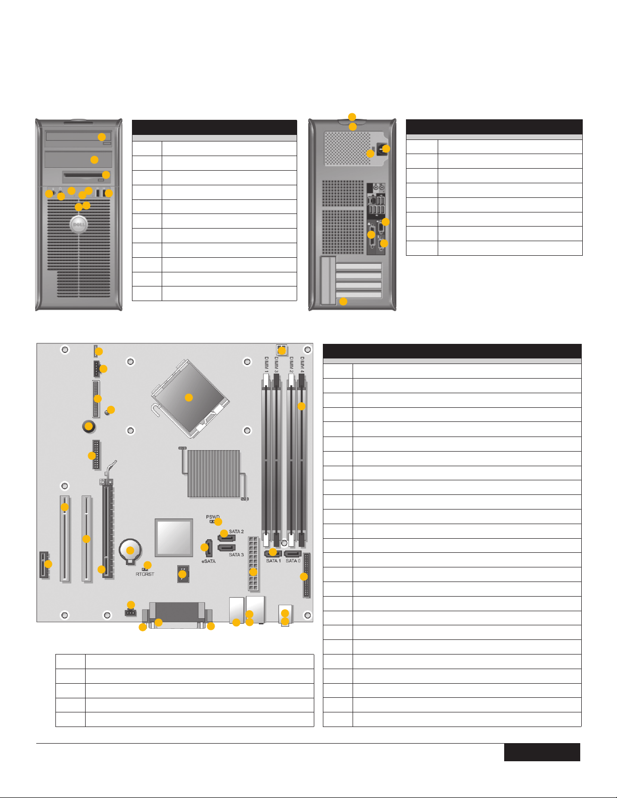
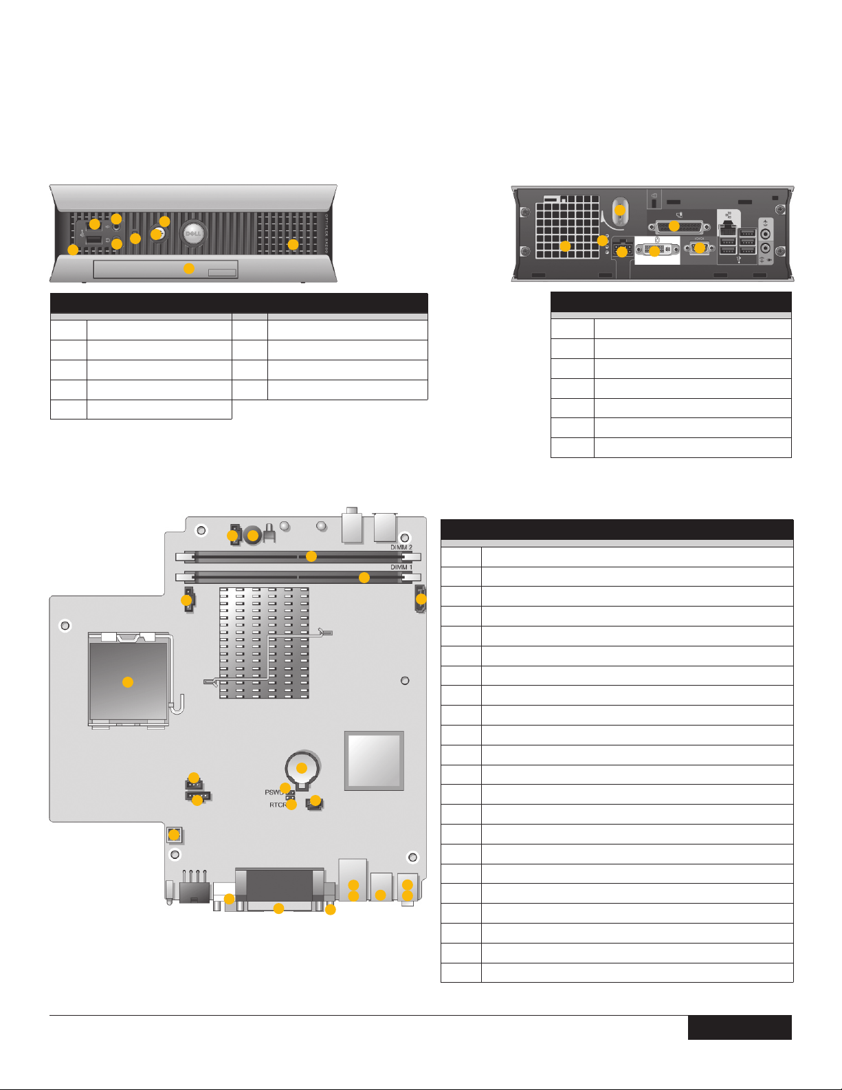
Mini towEr coMputEr (Mt) viEw
1
2
3
5
9
11
10
4
6
7
8
FRONT VIEW
5.25-inch drive bay
1
5.25-inch drive bay
2
3.5-inch drive bay
3
USB 2.0 connectors (2)
4
LAN indicator light
5
diagnostic lights
6
power button
7
power light
8
hard drive activity light
9
headphone connector
10
microphone connector
11
6
5
4
7
1
3
8
2
BACK VIEW
1
2
3
4
5
6
7
8
card slots
serial port
power connector
voltage selection switch
padlock ring
cover release latch
parallel port
VGA port
1
2
22
21
20
19
18
17
14
16
26
27
28
29
30
15
4x USB 2.0 ports
1 - RJ 45 network port
2 - USB 2.0 ports
stereo in/microphone
stereo out
12
13
24
23
3
6
7
10
11
28
27
26
25
4
7
9
29
30
SYSTEM BOARD COMPONENTS
speaker connector (INT_SPKR)
1
fan (FAN_CPU)
2
processor connector (CPU)
5
8
3
processor power connector (12VPOWER)
4
memory module connectors (DIMM_1, DIMM_2, DIMM_3, DIMM_4)
5
password jumper (PSWD)
6
SATA drive connectors (SATA0, SATA1, SATA2, SATA3)
7
front-panel connector (FRONTPANEL)
8
power connector (POWER)
9
external SATA connector (eSATA)
10
internal USB (INT_USB)
11
RTC reset jumper (RTCRST)
12
intrusion switch connector (INTRUDER)
13
battery socket (BATTERY)
14
PCI Express x16 connector (SLOT1)
15
PCI Express x1 connector (SLOT4)
16
PCI connector (SLOT2)
17
PCI connector (SLOT3)
18
serial connector (SERIAL2)
19
system board speaker (BEEP)
20
aux power LED (aux_LED)
21
oppy connector (DSKT)
22
VGA connector
23
parallel port
24
serial port
25
version 1.0 5
55
Page 6
DELL™ OPTIPLEX™ 755 TECHNICAL GUIDE
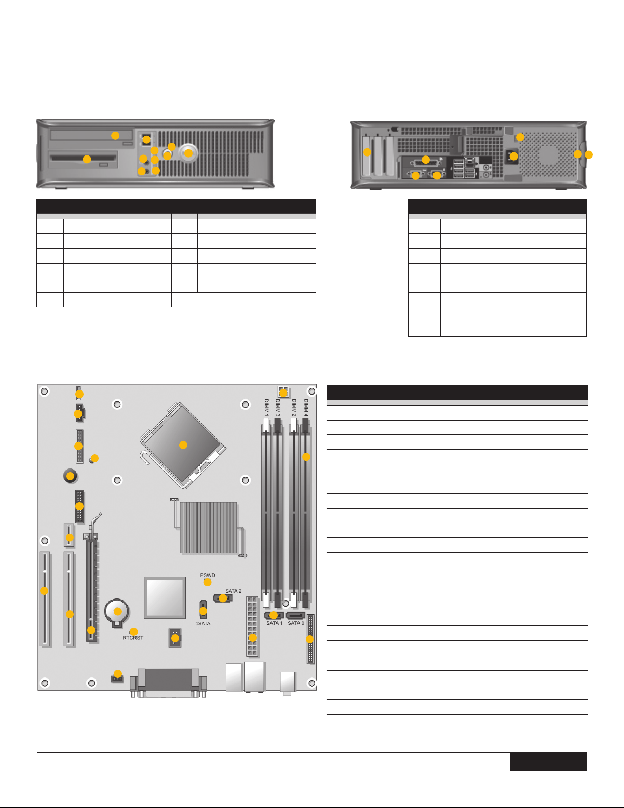
DEsktop coMputEr (Dt) viEw
10
FRONT VIEW
USB 2.0 connectors (2)
1
LAN indicator light
2
power button
3
Dell badge
4
power light
5
diagnostic lights
6
1
22
21
19
18
17
16
15
11
20
14
1
3
2
8
6
7
9
13
11
12
4
5
hard drive activity light
7
headphone connector
8
microphone connector
9
3.5-inch drive bay
10
5.25-inch drive bay
11
3
2
5
6
9
10
6
8
SYSTEM BOARD COMPONENTS
4
7
1
internal speaker (INT_SPKR)
1
processor connector (CPU)
2
processor power connector (12VPOWER)
3
memory module connectors (DIMM_1, DIMM_2, DIMM_3, DIMM_4)
4
password jumper (PSWD)
5
SATA connectors (SATA0, SATA1, SATA2)
6
front-panel connector (FRONTPANEL)
7
power connector (POWER)
8
external SATA connector (eSATA)
9
internal USB (INT_USB)
10
RTC reset jumper (RTCRST)
11
intrusion switch connector (INTRUDER)
12
battery socket (BATTERY)
13
PCI Express x16 connector (SLOT1)
14
PCI connector (SLOT2)
15
PCI connector (SLOT3)
16
riser connector (uses PCI-E port/SLOT1 and PCI port/SLOT2)
17
serial connector (SERIAL2)
18
system board speaker (BEEP)
19
aux power LED (aux_LED)
20
oppy connector (DSKT)
21
fan connector (FAN_CPU)
22
7
8
2
BACK VIEW
1
2
3
4
5
6
7
8
card slots
serial port
power connector
voltage selection switch
padlock ring
cover-release latch
parallel port
VGA port
4
5
3
6
version 1.0 6
6
Page 7
DELL™ OPTIPLEX™ 755 TECHNICAL GUIDE
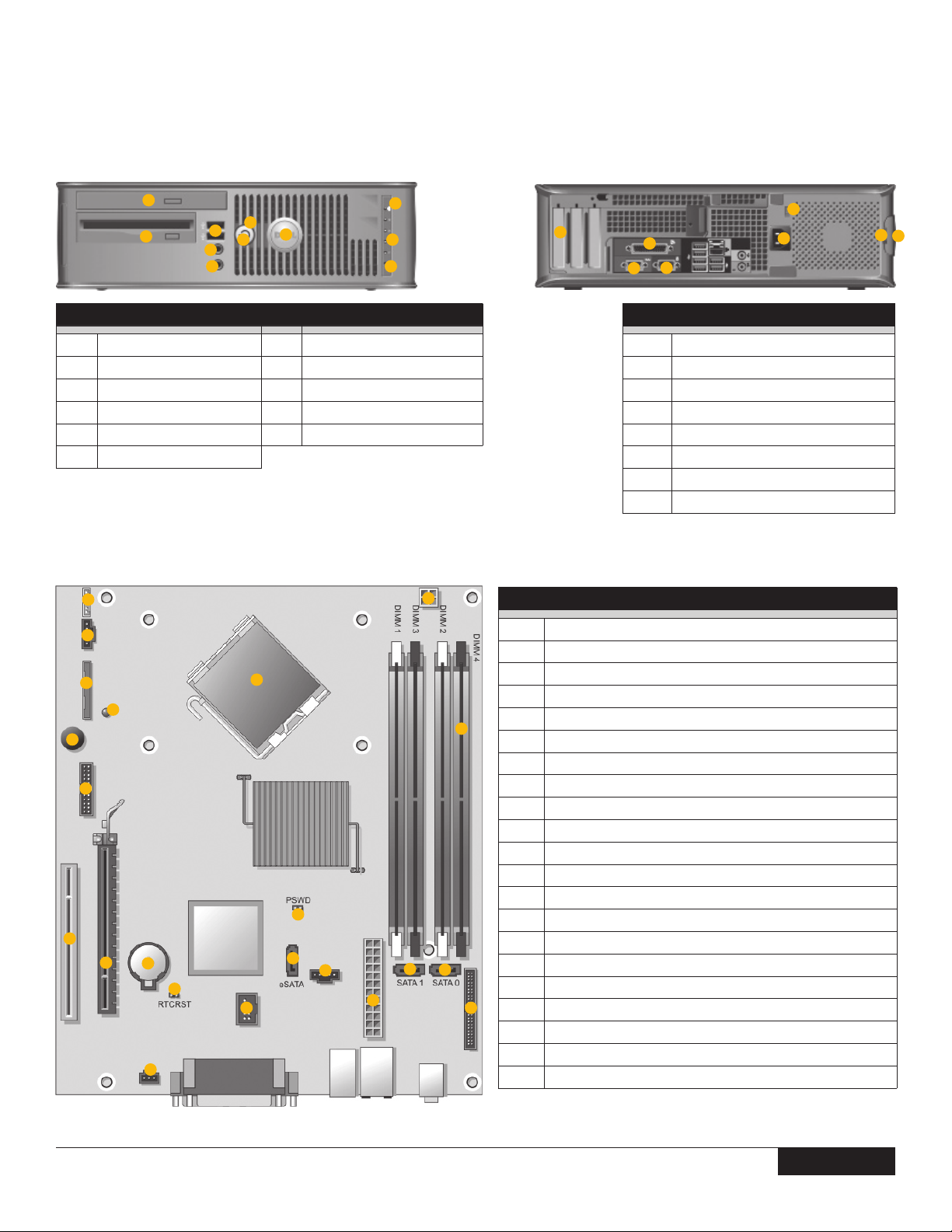
sMaLL forM factor coMputEr (sff) viEw
FRONT VIEW
USB 2.0 connectors (2)
1
power button
2
Dell badge
3
LAN indicator light
4
diagnostic lights
5
hard drive activity light
6
1
21
20
19
18
17
16
15
11
2
10
14
13
1
8
9
12
3
7
power light
7
headphone connector
8
microphone connector
9
3.5-inch drive bay
10
5.25-inch drive bay
11
2
5
10
9
11
4
5
6
3
4
6
6
8
SYSTEM BOARD COMPONENTS
7
1
internal speaker connector (INT_SPKR)
1
processor connector (CPU)
2
processor power connector (12VPOWER)
3
memory module connectors (DIMM_1, DIMM_2, DIMM_3, DIMM_4)
4
password jumper (PSWD)
5
SATA connectors (SATA0, SATA1)
6
front-panel connector (FRONTPANEL)
7
power connector (POWER)
8
fan connector (FAN_HDD)
9
eSATA connector (eSATA)
10
internal USB connector (INT_USB)
11
RTC reset jumper (RTCRST)
12
intrusion switch connector (INTRUDER)
13
battery socket (BATTERY)
14
PCI Express x16 connector (SLOT1)
15
PCI connector (SLOT2)
16
serial connector (SERIAL2)
17
system board speaker (BEEP)
18
aux power LED (aux_LED)
19
oppy drive connector (DSKT)
20
fan connector (FAN_CPU)
21
7
8
2
BACK VIEW
1
2
3
4
5
6
7
8
card slots
serial port
power connector
voltage selection switch
padlock ring
cover-release latch
parallel port
VGA port
4
5
3
6
version 1.0 7
7
Page 8
DELL™ OPTIPLEX™ 755 TECHNICAL GUIDE
uLtra sMaLL forM factor coMputEr (usff) viEw
2
1
9
FRONT VIEW
1
2
3
4
5
3
USB connectors (2)
headphone connector
microphone connector
power light
power button
5
4
8
7
6
7
8
9
6
vents
module bay
hard drive access light
vents
5
BACK VIEW
1
2
3
4
5
6
7
2 3
4
5
1
14
13
12
11
15
7
8
9
10
19
16
18
17
22
20
21
SYSTEM BOARD COMPONENTS
fan connector (FAN_FRONT)
1
internal speaker connector (INT_SPKR)
2
system board speaker (BEEP)
3
6
channel B memory connector (DIMM_2)
4
channel A memory connector (DIMM_1)
5
SATA data cable connector (SATA0)
6
battery (BATT)
7
password jumper (PSWD)
8
hard drive fan connector (FAN_HDD)
9
clear CMOS jumper (RTCRST)
10
hard drive power connector (SATA_PWR)
11
fan connector (FAN_REAR)
12
intrusion switch connector (INTRUDER)
13
processor (CPU)
14
DVI-1 connector
15
parallel port
16
serial port
17
1- RJ 45 network connector
18
2 - USB 2.0 connectors
19
3 - USB 2.0 ports
20
line-out connector
21
line-in microphone connector
22
2
3
1
7
4
6
diagnostic lights
computer cover release knob
parallel port
power connector
vents
serial port
DVH port
version 1.0 8
8
Page 9
DELL™ OPTIPLEX™ 755 TECHNICAL GUIDE
MarkEting systEM configurations
Oerings may vary by region. For more information regarding the configuration of your computer, click
Start Help and Support and select the option to view information about your computer.
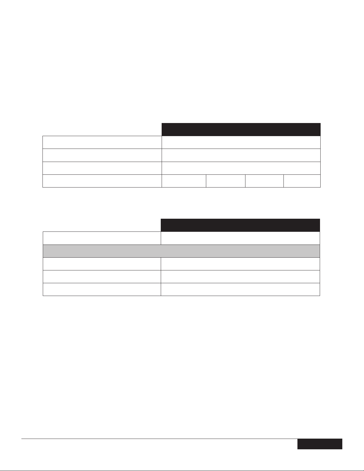
opErating systEM
One of the following Operating Systems will be preinstalled.
MT DT SFF USFF
Windows Vista® Operating System
Windows XP® Operating System
Other
OS Media Support
chipsEt
Chipset
Non-volatile Memory on Chipset
BIOS Conguration SPI (serial peripheral interface)
TPM 1.2 Security Device (Trusted Platform Module)
NIC EEPROM
Windows Vista® Ultimate 32-bit, Windows Vista® Business 32- and 64-bit,
Windows Vista® Home Basic 32 bit
Windows® XP Professional SP2, Windows® XP Home Edition SP2
(all 32-bit only)
FreeDOS for (n-series), Red Flag Linux (China only)
✓ ✓ ✓ ✓
MT DT SFF USFF
Intel® Q35 Express Chipset (ICH9DO)
32Mbit (4MB) located at SPI_FLASH on chipset
16KB located at TPM1P2 on chipset
LOM conguration contained within SPI_FLASH – no dedicated LOM EEPROM
version 1.0 9
9
9
Page 10
DELL™ OPTIPLEX™ 755 TECHNICAL GUIDE
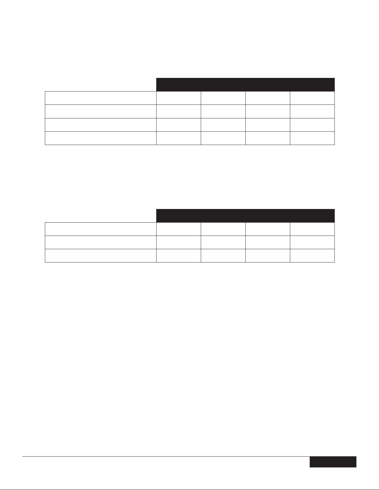
procEssor
Global Standard Products (GSP) are a subset of Dell’s relationship products that are managed for availability and synchronized
transitions on a worldwide basis. They ensure the same platform is available for purchase globally. This allows customers to reduce
the number of configurations managed on a worldwide basis, thereby reducing their costs. They also enable companies to implement
global IT standards by locking in specic product congurations worldwide. The following GSP processors identied below will be made
available to Dell customers.
Processor numbers are not a measure of performance.
PROCESSOR (SPEED, CACHE, FSB)
Intel® Core™ 2 Quad with Intel VT, Enhanced Intel SpeedStep Technology, Intel 64 and Execute Disable Bit
Intel Core 2 Quad Q6700 Processor (2.66GHz, 8MB L2 cache, 1066MHz FSB, VT)
Intel Core 2 Quad Q6600 Processor (2.4GHz, 8MB L2 cache, 1066MHz FSB, VT)
Intel® Core 2 Duo with Intel vPro Technology, Intel VT, Intel TXT, Enhanced Intel SpeedStep Technology, Intel 64 and Execute Disable Bit
Intel Core 2 Duo E6850 Processor (3.0GHz, 4MB L2 cache, 1333MHz FSB, vPro, VT)
Intel Core 2 Duo E6750 Processor (2.66GHz, 4MB L2 cache, 1333MHz FSB, vPro, VT)
Intel Core 2 Duo E6550 Processor (2.33GHz, 4MB L2 cache, 1333MHz FSB, vPro, VT)
Intel® Core 2 Duo with Enhanced Intel SpeedStep Technology, Intel 6.4 and Execute Disable Bit
Intel Core 2 Duo E4600 Processor (2.4GHz, 2MB L2 cache, 800MHz FSB)
Intel Core 2 Duo E4500 Processor (2.2GHz, 2MB L2 cache, 800MHz FSB)
Intel Core 2 Duo E4400 Processor (2.0GHz, 2MB L2 cache, 800MHz FSB)
Intel Core 2 Duo E2180 Processor (2.0GHz, 1MB L2 cache, 800MHz FSB)
Intel Core 2 Duo E2160 Processor (1.8GHz, 1MB L2 cache, 800MHz FSB)
MT DT SFF USFF
✓ ✓ ✓
✓ ✓ ✓
X-GSP X-GSP X-GSP X-GSP
X-GSP X-GSP X-GSP X-GSP
X-GSP X-GSP X-GSP X-GSP
✓ ✓ ✓ ✓
✓ ✓ ✓ ✓
✓ ✓ ✓ ✓
✓ ✓ ✓ ✓
✓ ✓ ✓ ✓
Intel Core 2 Duo E2140 Processor (1.6GHz, 1MB L2 cache, 800MHz FSB)
Intel® Celeron with Execute Disable Bit
Intel Celeron 440 Processor (2.0GHz, 512K L2 cache, 800MHz FSB)
Intel Celeron 430 Processor (2.0GHz, 512K L2 cache, 800MHz FSB)
version 1.0 10
✓ ✓ ✓ ✓
✓ ✓ ✓ ✓
✓ ✓ ✓ ✓
10
Page 11
DELL™ OPTIPLEX™ 755 TECHNICAL GUIDE
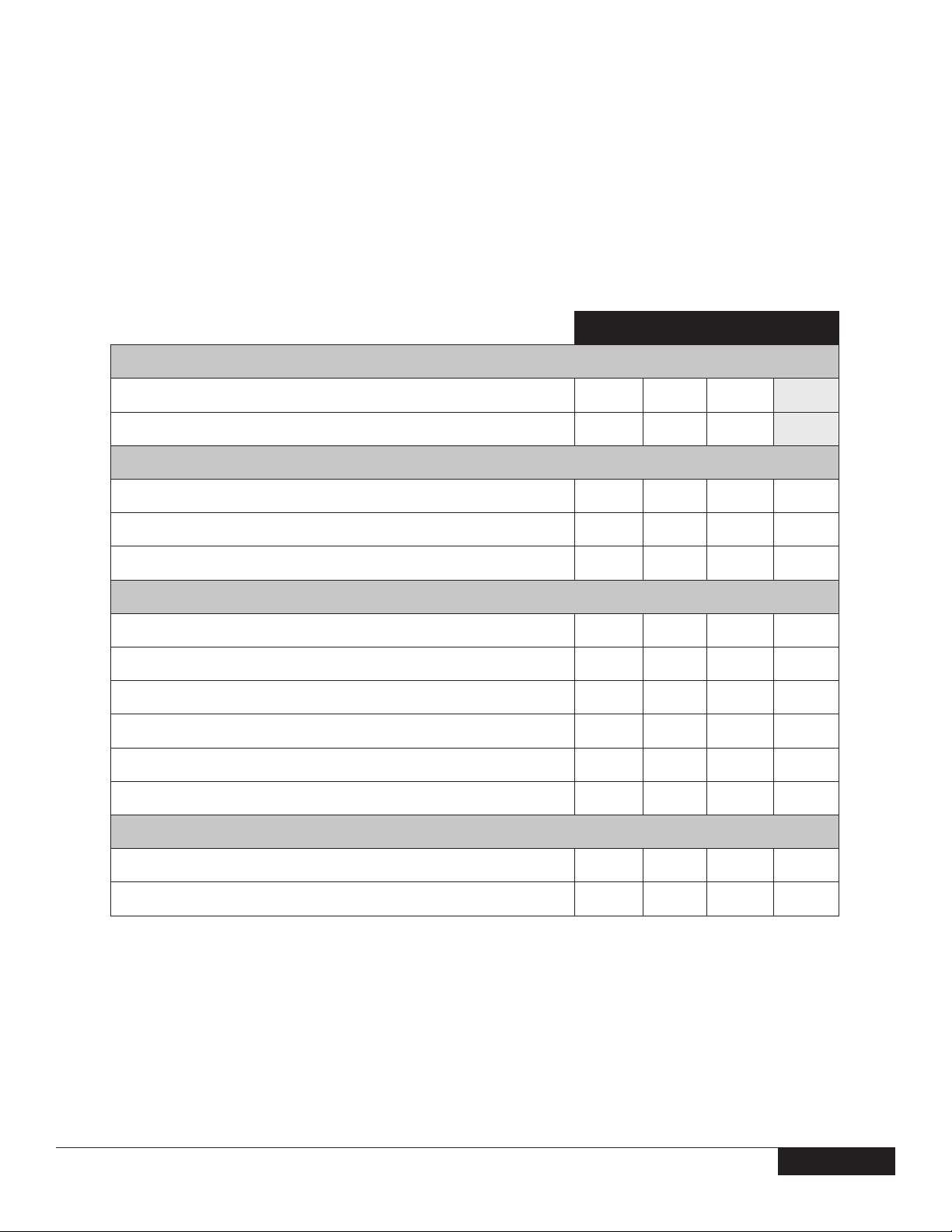
aDvancED systEM ManagEabiLity MoDEs
MT DT SFF USFF
Secure Advanced Client Systems Management1
(w/ vPro)
Advanced Client Systems Management
(w/ iAMT)
Basic Client Systems Management (w/ ASF)
Client Systems Management Disabled
1
Secure Advanced Client Systems Management requires Intel Core 2 Duo or Core 2 Quad Processors in addition to iAMT.
DEpLoyMEnt MoDE options
Requires Secure Advanced Client Systems Management (with/vPro) or Advanced Client Systems Management (with iAMT) modes only.
Deployment options to enable easy deployment of systems management options.
One-Touch Provisioning Support
TLS Encryption Disabled
Legacy ASF Setting for iAMT
✓ ✓ ✓ ✓
✓ ✓ ✓ ✓
✓ ✓ ✓ ✓
✓ ✓ ✓ ✓
MT DT SFF USFF
✓ ✓ ✓ ✓
✓ ✓ ✓ ✓
✓ ✓ ✓ ✓
version 1.0 11
11
Page 12

DELL™ OPTIPLEX™ 755 TECHNICAL GUIDE
MEMory
Your computer supports a maximum of 8GB of memory when you use four 2GB DIMMs; however, 32-bit operating systems, such as the
32-bit version of Microsoft® Windows® XP, can only use a maximum of 4GB of address space. Moreover, certain components within the
computer require address space in the 4GB range. Any address space reserved for these components cannot be used by computer
memory; therefore, the amount of memory available to the operating system is less than 4GB.
The entire 8GB memory range is available to 64-bit operating systems.
Memory modules should be installed in pairs of matched memory size, speed, and technology. If the memory modules are not installed
in matched pairs, the computer will continue to operate, but with a slight reduction in performance.
MT DT SFF USFF
DDR2 Synch DRAM Non-ECC Memory 667MHz or 800MHz speeds
DIMM Slots
DIMM Capacities
Minimum Memory
Maximum Memory with 667MHz Speed Memory
Maximum Memory with 800MHz Speed Memory
Configurations:
800MHz Memory Configurations
4GB1 DDR2 Non-ECC SDRAM, 800MHz,
(2 DIMM)
4GB1 DDR2 Non-ECC SDRAM, 800MHz,
(4 DIMM)
2GB DDR2 Non-ECC SDRAM, 800MHz,
(1DIMM)
2GB DDR2 Non-ECC SDRAM, 800MHz,
(2 DIMM)
1GB DDR2 Non-ECC SDRAM, 800MHz,
(1 DIMM)
667MHz Memory Configurations
4GB1 DDR2 Non-ECC SDRAM, 667MHz,
(4 DIMM)
4GB1 DDR2 Non-ECC SDRAM, 667MHz,
(2 DIMM)
3GB DDR2 Non-ECC SDRAM, 667MHz,
(4 DIMM)
2GB DDR2 Non-ECC SDRAM, 667MHz,
(4 DIMM)
2GB DDR2 Non-ECC SDRAM, 667MHz,
(2 DIMM)
1GB DDR2 Non-ECC SDRAM, 667MHz,
(2 DIMM)
1GB DDR2 Non-ECC SDRAM, 667MHz,
(1 DIMM)
512MB DDR2 Non-ECC SDRAM, 667MHz,
(1 DIMM)
1
The total amount of available memory will be less, depending on actual system configuration.
4 4 4 2
Up to 2GB Up to 2GB Up to 2GB Up to 2GB
512MB 512MB 512MB 512MB
1
8GB
1
8GB
✓ ✓ ✓ ✓
✓ ✓ ✓
✓ ✓ ✓ ✓
✓ ✓ ✓ ✓
✓ ✓ ✓ ✓
✓ ✓ ✓
✓ ✓ ✓ ✓
✓ ✓ ✓
✓ ✓ ✓
✓ ✓ ✓ ✓
✓ ✓ ✓ ✓
✓ ✓ ✓ ✓
✓ ✓ ✓ ✓
8GB
8GB
1
1
8GB
8GB
1
1
4GB
4GB
1
1
version 1.0 12
12
Page 13
DELL™ OPTIPLEX™ 755 TECHNICAL GUIDE
DrivEs anD rEMovabLE storagE
Bays:
MT DT SFF USFF
3.5-inch bay Externally Accessible
3.5-inch bay Internally Accessible
5.25-inch bay
Hard Drives Supported
1
Optical Drives Supported
Interface:
SATA (number of connectors - includes one dedicated
eSATA on MT, DT & SFF)
Floppy/Diskette
eSATA (requires additional bracket)
Hard Drive: Size, type, speed, RPM
80GB2 SATA 10K RPM HDD
250GB2 SATA 7200 RPM HDD
160GB2 High Reliability SATA 7200 RPM HDD
160GB2 SATA 7200 RPM HDD
80GB2 SATA 7200 RPM HDD
RAID 0 Enhanced Performance:
(includes two matching capacity/speed hard drives)
80GB2 SATA 10K RPM HDD
160GB2 SATA 7200 RPM HDD
320B2 SATA 7200 RPM HDD
500GB2 SATA 7200 RPM HDD
RAID 1 Data Protection:
(includes two matching capacity/speed hard drives)
80GB2 SATA 10K RPM HDD
1 1* 1 (slimline) D/bay module
2 1* 1 1
2 1 1 (slimline)
2 2 1 1
2 1 1 D/bay module
5 4 3 1
1 1 1
1 1 1
✓ ✓ ✓ ✓
✓ ✓ ✓ ✓
✓ ✓ ✓ ✓
✓ ✓ ✓ ✓
✓ ✓ ✓ ✓
✓ ✓
✓ ✓
✓ ✓
✓ ✓
3
3
3
3
✓ ✓
250GB2 SATA 7200 RPM HDD
160GB2 SATA 7200 RPM HDD
80GB2 SATA 7200 RPM HDD
1
This only pertains to drives physically contained within the chassis and does not refer to HDDs attached via eSATA (including port multiplier), USB or optional 1394.
2
For hard drives, GB means 1 billion bytes and TB equals 1 trillion bytes; actual capacity varies with preloaded material and operating environment and will be less.
3
RAID 1 in DT chassis restricted to Western Digital and Samsung HDDs.
* Card length can be longer than standard Half-Length Card but cannot be a Full-Length Card.
version 1.0 13
✓ ✓
✓ ✓
✓ ✓
13
Page 14
DELL™ OPTIPLEX™ 755 TECHNICAL GUIDE
DrivEs anD rEMovabLE storagE, cont.
MT DT SFF USFF
Optical Drive:
DVD+/-RW
DVD-ROM
Combo Drive CD-RW
CD-ROM
16x SATA 8x EIDE 8x EIDE
16x SATA 8x EIDE 8x EIDE
48x/32x/48x/16x SATA 24x/24x/24x EIDE 24x/24x/24x EIDE
48x SATA 24x EIDE 24x EIDE
Floppy Diskette Drive:
Floppy Drive
1.44MB 1.44MB (slimline) 1.44MB (D/Bay)
Media Card Reader: (uses Externally Accessible 3.5-inch bay)
Dell 19-in-1 Media Card Reader
✓ ✓ ✓
systEM boarD connEctors
See Detailed Engineering Specications for maximum card dimensions support.
SFF requires
a slimline
optical drive
USFF requires
a D-module
Slimline drive
PCI Slot(s):
PCIe x16 Slot:
PCIe x1 Slot:
Flexbay (used for Media Card Reader)
Serial ATA (SATA) (Includes eSATA Connector)
MT DT SFF USFF
2 2 1
1 1 1
1
1 1 1
5 4 3 1
version 1.0 14
14
Page 15

DELL™ OPTIPLEX™ 755 TECHNICAL GUIDE
systEM boarD connEctor MaxiMuM aLLowabLE DiMEnsions
MT DT SFF USFF
PCI Slot(s) Dimensions: (HxL)
Height i n c h e s /c e n t i m e t e r s
Length i n c h e s /c e n t i m e t e r s
PCIe x16 Slot Dimensions: (HxL)
Height i n c h e s /c e n t i m e t e r s
Length i n c h e s /c e n t i m e t e r s
PCIe x1 Slot Dimensions: (HxL)
Height i n c h e s /c e n t i m e t e r s
Length i n c h e s /c e n t i m e t e r s
Combo Full Height Riser with 1 PCI and
1 PCIe connector (HxL)
Height i n c h e s /c e n t i m e t e r s
Length i n c h e s /c e n t i m e t e r s
Dual Full Height Riser with 2 PCI connectors
(HxL)
Height i n c h e s /c e n t i m e t e r s
2 2 1
4.376 / 11.115 2.731 / 6.89
6.6 / 16.765* 6.6 / 16.765
1 1 1
4.376 / 11.115 2.731 / 6.89
6.6 / 16.765* 6.6 / 16.765
1
4.376 / 11.115
6.6 / 16.765
1 /1
4.376 / 11.115
6.9 / 17.53**
2
4.376 / 11.115
Length i n c h e s /c e n t i m e t e r s
* Card length can be longer than standard Half-Length Card but cannot be a Full-Length Card.
** 6.9/17.53 in/cm is longer than the standard Half-Length Card. Risers replace 1 PCl slot and 1 PCle slot on DT system board.
6.9 / 17.53**
graphics/viDEo controLLEr
MT supports full height card, DT supports low prole card or full height card with optional riser. SFF supports low prole card.
MT DT SFF USFF
Integrated Intel® Graphics Media
Accelerator 3100*
Integrated on system board
Enhanced Graphic/Video Options
DVI (Digital)
* Signicant memory may be used to support graphics, depending on system memory size and other factors.
Optional full height or low prole Add-2 card
Native DVI
Connector
version 1.0 15
15
Page 16

DELL™ OPTIPLEX™ 755 TECHNICAL GUIDE
graphics/viDEo controLLEr, cont.
Enhanced Graphic/Video Options , Cont.
MT DT SFF USFF
128MB ATI Radeon X1300* with DVI and
TV Out
256MB ATI Radeon™ HD 2400 PRO* with
DVI and TV Out
256MB ATI Radeon™ HD 2400 XT* Dual
Monitor with VGA cable and TV Out
256MB ATI Radeon™ HD 2400 XT* Dual
Monitor with DVI and VGA cables and TV Out
* Signicant system memory may be used to support graphics, depending on system memory size and other factors.
INTEGRATED INTEL GRAPHICS
MEDIA ACCELERATOR 3100
*
Optional full height or low profile card
Optional full height or low profile card
Optional full height or low profile card
Optional full height or low profile card
MT DT SFF USFF
Bus Type
GPU Core Clock
Frame Buffer Memory Size
350 MHz Integrated 24 bit RAMDAC
Up to 256MB of shared system memory*
Maximum Power Consumption
Overlay Planes
Maximum Color Depth
Integrated
9.63 W
Yes
32 bit
Maximum Vertical Refresh Rate
Multiple Display Support
Operating Systems Graphics/ Video API Support
Supported Resolutions and Max Refresh Rates
(Hz) (Note: analog and/or digital)
External Connectors
Dimensions i n c h e s /c e n t i m e t e r s (L x H)
Yes, with optional DVI Add-2 card
OpenGL® 1.4/DirectX 9.0c
Supports at panels up to 1920x1200 @ 60 Hz or
digital CRT/HDTV at 1400x1050 @ 85 Hz
VGA DVI
85 Hz
Up to 2048x1566 @ 75 Hz
N/A
Environmental Operating Conditions:
Operating Temperature Range
Relative Humidity Range
Altitude Range
* Signicant system memory may be used to support graphics, depending on system memory size and other factors.
version 1.0 16
0° to 106° C (32° to 223° F)
20% to 80% (non-condensing)
–15.2 to 3048 m (–50 to 10,000 ft)
16
Page 17

DELL™ OPTIPLEX™ 755 TECHNICAL GUIDE
DVI (DIGITAL) ADD-2 CARD
Bus Type
Maximum Supported Resolution
Dimensions of Full Height Card
i n c h e s /c e n t i m e t e r s (L x H)
Dimensions of Low Profile Card
i n c h e s /c e n t i m e t e r s (L x H)
Maximum Power Consumption
External Connectors
128MB ATI RADEON X1300
WITH DVI AND TV OUT
Bus Type
GPU Core Clock
Frame Buffer Memory (onboard) Size and Speed
MT DT SFF USFF
sDVO
Up to 2048x1566 @ 75 Hz
Supports at panels up to 1920x1200 @ 60 Hz or digital CRT/
HDTV at 1400x1050 @ 85 Hz
5.75x2.75in/
14.61x6.99cm
5.75x2.75in/
14.61x6.99cm
DVI
MT DT SFF USFF
PCIEx16
400Mhz
128MB 400Mhz
Maximum Power Consumption
Overlay Planes
Maximum Color Depth
Maximum Vertical Refresh Rate
Multiple Display Support
Operating Systems Graphics/ Video API Support
Supported Resolutions and Max Refresh Rates
(Hz) (Note: analog and/or digital)
External Connectors
Dimensions of Full Height Card
i n c h e s /c e n t i m e t e r s (L x H)
Dimensions of Low Profile Card
i n c h e s /c e n t i m e t e r s (L x H)
Environmental Operating Conditions:
Operating Temperature Range
Relative Humidity Range
20W
Yes
32-bit
85Hz
No
D3D and Open GL
Max : 1920x1440/32bpp @ 75Hz
Min : 640x480/8bpp @ 60Hz
DVI-D and S-video with Composite
6.6x4.72in/167.64x120mm
6.6x3.35in/167.64x85mm
50°-122°F (10°-50° C)
5-90% RH (non-condensing)
®
Altitude Range
version 1.0 17
0-20,000 ft.
17
Page 18

DELL™ OPTIPLEX™ 755 TECHNICAL GUIDE
graphics/viDEo controLLEr, cont.
256MB ATI RADEON™ HD 2400 PRO
WITH DVI AND TV OUT
Bus Type
GPU Core Clock
Frame Buffer Memory (onboard) Size and Speed
Maximum Power Consumption
Overlay Planes
Maximum Color Depth
Maximum Vertical Refresh Rate
Multiple Display Support
Operating Systems Graphics/ Video API Support
Supported Resolutions and Max Refresh Rates
(Hz) (Note: analog and/or digital)
External Connectors
Dimensions of Full Height Card
i n c h e s /c e n t i m e t e r s (L x H)
Dimensions of Low Profile Card
i n c h e s /c e n t i m e t e r s (L x H)
MT DT SFF USFF
PCIEx16
400MHz
256MB 500Mhz
21W
Yes
32-bit
85Hz
No
D3D and Open GL
Max : 1920x1440/32bpp @ 75Hz
Min : 640x480/8bpp @ 60Hz
DVI-D and S-video
6.6x4.72in/167.64x120mm
6.6x3.35in/167.64x85mm
Environmental Operating Conditions:
Operating Temperature Range
Relative Humidity Range
Altitude Range
version 1.0 18
50°-122°F (10°-50° C)
5-90% RH (non-condensing)
0-20,000 ft.
18
Page 19

DELL™ OPTIPLEX™ 755 TECHNICAL GUIDE
graphics/viDEo controLLEr, cont.
256MB ATI RADEON™ HD 2400 XT DUAL
MONITOR WITH DVI/VGA VIA CABLES
AND TV OUT
Bus Type
MT DT SFF USFF
PCIEx16
GPU Core Clock
Frame Buffer Memory (onboard) Size and Speed
Maximum Power Consumption
Overlay Planes
Maximum Color Depth
Maximum Vertical Refresh Rate
Multiple Display Support
Operating Systems Graphics/ Video API Support
Supported Resolutions and Max Refresh Rates
(Hz) (Note: analog and/or digital)
External Connectors
Dimensions of Full Height Card
i n c h e s /c e n t i m e t e r s (L x H)
Dimensions of Low Profile Card
i n c h e s /c e n t i m e t e r s (L x H)
Environmental Operating Conditions for Graphics Cards:
600Mhz
256MB 500Mhz
25W
Yes
32-bit
85Hz
2
D3D, Open GL
Max : 1920x1440/32bpp @ 75Hz
Min : 640x480/8bpp @ 60Hz
DMS-59
6.6x4.72in/167.64x120mm
6.6x3.35in/167.64x85mm
Operating Temperature Range
Relative Humidity Range
Altitude Range
version 1.0 19
50°-122°F (10°-50° C)
5-90% RH (non-condensing)
0-20,000 ft.
19
Page 20

DELL™ OPTIPLEX™ 755 TECHNICAL GUIDE
ExtErnaL ports/connEctors
MT supports full height cards, DT supports low prole cards or full height cards with optional riser. SFF supports low prole cards.
See chassis diagrams section for
port/connector locations
MT DT SFF USFF
USB 2.0 (totals)
Front
Back
Internal
Serial
PS/2 and 1 additional Serial
(low profile bracket includes PS/2 dongle)
eSATA Bracket
Parallel
Network Connector (RJ-45)
1394 Controller
Video:
VGA
DVI
Audio:
10 7
2 2
6 5
2 0
One rear
Optional full height or low profile bracket
Optional full height or low profile bracket
One rear
One rear
Optional full height or low profile card
One rear
Optional full height or low prole Add-2 card One rear
Microphone-in
Headphone
Stereo line-in
Speakers line out
One minijack front
One minijack front
One minijack front
One minijack rear
Risers:
(replaces 1 PCI slot and 1 PCIe slot on DT system board)
Combo full height riser with 1 PCI and
1 PCIe connector
Dual full height riser with 2 PCI connectors
version 1.0 20
✓
✓
20
Page 21

DELL™ OPTIPLEX™ 755 TECHNICAL GUIDE
coMMunications - nEtwork aDaptEr (nic)
MT supports full height card, DT supports low prole card or full height card with optional riser. SFF supports low prole card.
MT DT SFF USFF
Intel® 82566DM Gigabit LAN 10/100/1000
(Remote Wake Up, PXE, and Intel Active Management
Technology support)
Broadcom NetXtreme 10/100/1000 PCIe
Gigabit Networking Card
INTEGRATED INTEL 82566DM GIGABIT LAN
External Connector Type
Data Rates Supported
Controller Details
Controller bus architecture
Integrated memory
Data transfer mode
Power consumption
(full operation per data rate connection speed)
Power consumption (standby operation)
IEEE Standards Compliance
Integrated on system board
Supports
full height
Intel Gigabit LAN Connect Interface (GLCI) and LAN Connect Interface (LCI)
Low profile
card or full
height card with
optional riser
RJ45
10/100/1000 Mbps
N/A
N/A
1000 Mbps: 2468 mW
100 Mbps: 772 mW
10 Mbps: 607 mW
No Link (no wake): 40 mW
10 Mbps Idle (wake): 271 mW
100 Mbps Idle (wake): 756 mW
802.3ab
Supports low
profile card
Hardware Certifications
Boot ROM Support
EEPROM (located in SPI)
N/A
Network Transfer Mode
Network Transfer Rate
10BASE-T (full-duplex) 20 Mbps
100BASE-TX (half-duplex) 100 Mbps
100BASE-TX (full-duplex) 200 Mbps
Full duplex at 10, 100, or 1000 Mbps and
half duplex at 10 or 100 Mbps.
1000BASE-T (full-duplex) 2000 Mbps
Environmental
Operating temperature
Operating humidity
Operating System Driver Support
Windows® XP, Windows Vista® Ultimate, Windows Vista® Business 32 bit/64 bit,
Manageability
Management Capabilities Alerting
version 1.0 21
0° C to 70° C (32° F to 158° F)
20% to 80% (non-condensing)
Windows Vista Home Basic, Linux
WOL, PXE
ASF2.0, AMT 3.0
21
Page 22

DELL™ OPTIPLEX™ 755 TECHNICAL GUIDE
coMMunications - nEtwork aDaptEr (nic), cont.
BROADCOM NETXTREME 10/100/1000
PCIE GIGABIT NETWORKING CARD
MT DT SFF USFF
Connector Type
Data Rates Supported
Controller Details
Controller bus architecture
Integrated memory
Data transfer mode
Power consumption
(full operation per data rate connection speed)
Power consumption (standby operation)
IEEE Standards Compliance
Hardware Certifications
Boot ROM Support
Network Transfer Mode
Network Transfer Rate
RJ-45
10/100/1000 Mbps Half/full duplex
PCIe c1.0a x1
64KBytes RX, 8KBytes TX
Bus-Master DMA
2.84W (860mA @ +3.3V)
Less than 300mW
802.3, 802.2, 802.3x, 802.1p
FCC B, VCCI B, CE
No
Full Duplex/Half Dup[lex
10BASE-T (full-duplex) 20 Mbps Max*
100BASE-TX (half-duplex) 100 Mbps Max*
100BASE-TX (full-duplex) 200 MbpsMax*
1000BASE-T (full-duplex) 2000 Mbps Max*
* Depends on the system environment.
Environmental
Operating temperature
Operating humidity
Operating System Driver Support
Windows® XP, Windows Vista® Ultimate, Windows Vista®
Business 32 bit/64 bit, Windows Vista Home Basic, Linux
Manageability
Management Capabilities Alerting
version 1.0 22
0° C to 55° C (32° F - 131° F)
5% ~ 85% (non-condensing)
WOL, PXE2.1, ACPI
None
22
Page 23

DELL™ OPTIPLEX™ 755 TECHNICAL GUIDE
coMMunications – MoDEM
MT supports full height card, DT supports low prole card or full height card with optional riser. SFF supports low prole card.
V.92 DATA/FAX
CONTROLLERLESS MODEM
Bus
External Connector
Data Transmission
Data Speeds
Data Standards
Fax Speeds
Fax Mode Capabilities
Error Correction and Data Compression
Power Management
Upgradeability
Video
MT DT SFF USFF
Supports
full height
PCM - Pulse Coded Modulation (V.92/V.90)
TCM - Trellis Coded Modulation (V.90/V.34/V.32 bis/V.32)
56kbps receive, 48kbps transmit
ITU V.92/V.90, V.34/V.32 bis/V.32
2-wire, half-duplex, synchronous
V.44, V.42, V.42bis, MNP 2-4, MNP 5
V.80 Synchronous Access Mode (SAM) can be
supported by software applications (not driver)
Low profile
card or full
height card with
optional riser
PCI
RJ-11
14.4kbps
WOR (wake on ring) capable
Driver upgradeable
Supports low
profile card
Operating Temperature
Operating Humidity
Operating System Support
Operating System Driver Support
Power Requirements
Chipset
Dimensions of Full Height Card
i n c h e s /c e n t i m e t e r s (L X H)
Dimensions of Low Profile Card
i n c h e s /c e n t i m e t e r s (L X H)
0° C-50° C (32° F-122° F)
45° C (113° F) 90% max
Vista 32/64, Windows XP 32/64
Vista 32/64, Windows XP 32/64
+3.0V~+3.6V, 116.6mW max
Conexant SmartHSFs/LF (CX11256 & CX20493)
L: 5.25in/13.325cm H: 4.73in/12.002cm
L: 5.26in/13.366cm H: 3.12in/7.923cm
version 1.0 23
23
Page 24

DELL™ OPTIPLEX™ 755 TECHNICAL GUIDE
auDio anD spEakErs
MT DT SFF USFF
ADI 1984 High Definition Audio
Internal Chassis Speaker
Dell A225 Speakers
Dell A525 Speakers
Dell AS501 Flat Panel Speakers (Sound Bar)
Dell AS501PA Flat Panel Speakers (Sound Bar)
kEyboarD anD MousE
Dell USB Entry QuietKey Keyboard
Dell USB Enhanced Multimedia Keyboard
Dell Smart Card USB Keyboard
Dell Bluetooth Keyboard and Mouse
Dell USB Entry 2-Button Scroll Mouse
Integrated on system board
Optional
Optional
Optional
Optional
Optional
MT DT SFF USFF
Optional
Optional
Optional
Optional
Optional
Dell USB Optical 2-Button Scroll Mouse
Dell USB Premium 5-Button Mouse
Dell Palmrest
Dell Logo Mouse Pad
Optional
Optional
Optional
Optional
sEcurity
MT DT SFF USFF
Trusted Platform Module (TPM) 1.2
Chassis Intrusion Switch
Dell USB External Biometric Fingerprint Reader
Chassis Lock Slot
version 1.0 24
Integrated on system board
Optional
Optional
Standard
24
Page 25

DELL™ OPTIPLEX™ 755 TECHNICAL GUIDE
sErvicE anD support
For more details on Dell Service Plans please to go to www.dell.com/service/service_plans/
MT DT SFF USFF
3-Year Limited Warranty1 (3-3-0)
3-Year Next Business Day On-site2 Service
(3-3-3)
Gold Tech Support
1
For a copy of limited warranty, write Dell USA L.P., Attn: Warranties, One Dell Way, Round Rock, TX 78682 or visit www.dell.com/warranty.
2
May be provided by third-party. Technician dispatched, if necessary, following phone-based troubleshooting. Availability varies. See dell.com/servicecontracts for details.
Standard
Optional
Optional
softwarE
MT DT SFF USFF
Dell Client Manager Standard
Wave EMBASSY® Trust Suite
Norton Internet Security
McAfee Security Center
Available via Dell.com
Standard
90-Day Trial or Optional Subscription
90-Day Trial or Optional Subscription
version 1.0 25
25
Page 26

DELL™ OPTIPLEX™ 755 TECHNICAL GUIDE
DEtaiLED EnginEEring spEcifications
systEM DiMEnsions (physicaL)
System Weight1 and Shipping Weight1 is based on a typical conguration and may vary based on PC conguration. A typical conguration
includes: integrated graphics, one hard drive, one optical drive, and one diskette drive.
MT DT SFF USFF
Chassis Volume l i t e r s
Chassis Weight1 p o u n d s /k i l o g r a m s
33.0 16.0 10.7 6.0
25.8 / 11.70 18.2 / 8.26 15 / 6.80 10 / 4.54
Chassis Dimensions: (HxWxD)
Height i n c h e s /c e n t i m e t e r s
Width i n c h e s /c e n t i m e t e r s
Depth i n c h e s /c e n t i m e t e r s
Shipping Weight1 p o u n d s /k i l o g r a m s
(includes packaging materials)
Packaging Parameters (HxWxD)
2
Height i n c h e s /c e n t i m e t e r s
Width i n c h e s /c e n t i m e t e r s
Depth i n c h e s /c e n t i m e t e r s
1
Weights are approximates and may change based on system conguration and included accessories.
2
Dimensions are DAO specic. Each region has unique packing.
16.3 / 41.4 4.5 / 11.4 3.65 / 9.26 10.3 / 26.4
7.3 / 18.5 15.7 / 39.9 12.4 / 31.4 3.5 / 8.9
17.3 / 43.9 13.9 / 35.3 13.4 / 34 9.9 / 25.3
43.5 / 19.73 28 / 12.7 21.3 / 9.66 26.1 / 11.84
22.38 / 56.85 20.63 / 52.4 20.88 / 50.04 19.88 / 50.5
22.25 / 56.52 20.31 / 51.59 19.38 / 49.23 17.5 / 44.45
14.25 / 36.2 11.75 / 29.85 10.63 / 27 10.44 / 26.52
version 1.0 26
26
Page 27

DELL™ OPTIPLEX™ 755 TECHNICAL GUIDE
systEM LEvEL EnvironMEntaL anD opErating conDitions
Temperature
MT DT SFF USFF
Operating
Non-Operating (Storage)
Relative Humidity
Maximum Vibration
Operating
Non-Operating (Storage)
Maximum Shock
Operating
Non-Operating (Storage)
Maximum Altitude
Operating
Non-Operating (Storage)
10° to 35° C (50° to 95° F)
-40° to 65° C (-40° to -149° F)
20% to 80% (non-condensing)
0.25 G at 3 to 200 Hz at 0.5 octave/min
0.5 G at 3 to 200 Hz at 1 octave/min
Bottom half-sine pulse with a change in velocity of 50.8 cm/sec (20 inches/sec)
27-G faired square wave with a velocity change of 508 cm/sec (200 inches/sec)
–15.2 to 3,048 m (–50 to 10,000 ft)
–15.2 to 10,668 m (–50 to 35,000 ft)
version 1.0 27
27
Page 28

DELL™ OPTIPLEX™ 755 TECHNICAL GUIDE
powEr
MT DT SFF USFF
Power Supply Wattage
AC Input Voltage Range
AC Input Current
(low ac range/high AC range)
AC Input Frequency
AC Holdup Time
(50% load)
Minimum Efciency
Energy Star 4.0
Compliant Power Supply
PFC (Active)
DC Parameters
+3.3v Output
+5.0v Output
+12.0v Output
305W
90-135A/
180-
264A
9.0A/4.5A 4.5A/2.3A 9.0A/4.5A 4.5A/2.3A 8.8A/4.3A 4.3A/2.2A 3.2A/1.7A
50/60Hz 50/60Hz 50/60Hz 50/60Hz 50/60Hz 50/60Hz 50/60Hz
16ms 16ms 16ms 16ms 16ms 16ms 10ms at 100% load
65% 80% 65% 80% 65% 80% 85%
305W
High
Efficiency
90-264A
280W
90-135A/
180-
264A
280W
High
Efficiency
90-264A
275W
90-135A/
180-
264A
275W
High
Efficiency
90-264A 90-264A
220W High Efciency
External PSU
✓ ✓ ✓ ✓
✓ ✓ ✓ ✓
17.0A 17.0A 10.0A 10.0A 5.0A 5.0A
22.0A 22.0A 15.0A 15.0A 18.0A 18.0A
18.0+18.0A 18.0+18.0A 16.0A 16.0A 17.0A 17.0A 18.0A
+5.0v Auxiliary Output
-12.0v Output
Max Total Power
Max Combined
+3.3v / +5.0v Power
Max Combined
12.0v Power
BTUs/h
(based on PSU max wattage)
4.0A 4.0A 4.0A 4.0A 4.0A 4.0A
1.0A 1.0A 0.5A 0.5A 0.5A 0.5A
305W 305W 280W 280W 275W 275W 220W
150W 150W 108W 108W 106W 106W
264W 264W N/A N/A N/A N/A
1600 1300 1468 1195 1444 1171 880
3.3v CMOS Battery
(type and estimated battery life)
RTC accuracy
(time of day)
Power Supply Fan
Sleeve
bearing
Power Supply Meets Requirements of:
Energy Star 4.0
Compliant Power Supply
N Y N Y N Y Y
Sleeve
bearing
3-V CR2032 lithium coin cell. Est. 5-year life
Drift 2 seconds per month
Sleeve
bearing
Sleeve
bearing
Ball
bearing
Ball
bearing
None
version 1.0 28
28
Page 29

DELL™ OPTIPLEX™ 755 TECHNICAL GUIDE
powEr, cont.
MT DT SFF USFF
Blue Angel Compliant
UL Certied
FEMP Executive
Order 13221
auDio
INTEGRATED ADI 1984
HIGH DEFINITION AUDIO
High Definition Stereo Support
Number of Channels
Number of Bits / Audio Resolution
Sampling Rate (recording/playback)
Signal to Noise Ratio
Wavetable Voices
N Y N Y N Y Y
✓ ✓ ✓ ✓ ✓ ✓ ✓
N Y N Y N Y Y
MT DT SFF USFF
✓ ✓ ✓ ✓
2
16, 20, and 24-bit resolution
Independent 8, 11.025, 16, 22.05, 32, 44.1,
48, 88.2, 96, 176.4, and 192 kHz sample rates
96+ dB audio outputs, 90+ dB audio inputs
Analog Audio
Dolby Digital
THX
Digital Out (S/PDIF)
Audio Jack Impedance
Microphone
Line-In
Line-Out
Headphone
Internal Speaker Power Rating
✓ ✓ ✓ ✓
150 kΩ
150 kΩ
190 kΩ
.5 Ω
2 Watts
version 1.0 29
29
Page 30

DELL™ OPTIPLEX™ 755 TECHNICAL GUIDE
harD DrivEs
80GB SATA 10000 RPM HDD
1
Capacity (b y t e s )
Dimensions i n c h e s (W x D x H)
Interface Type and Maximum Speed
Internal Buffer Size (range)
Average Seek Time
Rotational Speed
Logical Blocks
Power Source
DC Power (Max)
DC Current
Environmental Operating Conditions:
Temperature Range
MT DT SFF USFF
80,026,361,856
5.87 x 4 x 1
Up to 3Gb/s
16MB
4.6 ms
10000 rpm
156,301,488
Idle 7.0W, Active 10.0W
5V (.8A) and 12V (1.8A)
41°F to 140°F (5°C to 60°C)
Relative Humidity Range
Maximum Wet Bulb Temperature
Altitude Range
20% to 80% non-condensing
84°F (29°C)
-50 ft to 10000 ft
Environmental Non-Operating Conditions:
Temperature Range
Relative Humidity Range
Maximum Wet Bulb Temperature
Altitude Range
1
For hard drives, GB means 1 billion bytes and TB equals 1 trillion bytes; actual capacity varies with preloaded material and operating environment and will be less.
-40°F to 149°F (-40°C to 65°C)
10% to 90% non-condensing
100.4°F (38°C)
-50 ft to 35000 ft
version 1.0 30
30
Page 31

DELL™ OPTIPLEX™ 755 TECHNICAL GUIDE
harD DrivEs, cont.
80GB SATA 7200 RPM HDD
1
Capacity (b y t e s )
Dimensions i n c h e s (W x D x H)
Interface Type and Maximum Speed
Internal Buffer Size (range)
Average Seek Time
Rotational Speed
Logical Blocks
Power Source
DC Power (Max)
DC Current
Environmental Operating Conditions:
Temperature Range
MT DT SFF USFF
80,026,361,856
5.87 x 4 x 1
Up to 3Gb/s
8MB
8.5 ms
7200 rpm
156,301,488
Idle 7.0W, Active 10.0W
5V (.8A) and 12V (1.8A)
41°F to 140°F (5°C to 60°C)
Relative Humidity Range
Maximum Wet Bulb Temperature
Altitude Range
20% to 80% non-condensing
84°F (29°C)
-50 ft to 10000 ft
Environmental Non-Operating Conditions:
Temperature Range
Relative Humidity Range
Maximum Wet Bulb Temperature
Altitude Range
1
For hard drives, GB means 1 billion bytes and TB equals 1 trillion bytes; actual capacity varies with preloaded material and operating environment and will be less.
-40°F to 149°F (-40°C to 65°C)
10% to 90% non-condensing
100.4°F (38°C)
-50 ft to 35000 ft
version 1.0 31
31
Page 32

DELL™ OPTIPLEX™ 755 TECHNICAL GUIDE
harD DrivEs, cont.
160GB SATA 7200 RPM HDD
1
Capacity (b y t e s )
Dimensions i n c h e s (W x D x H)
Interface Type and Maximum Speed
Internal Buffer Size (range)
Average Seek Time
Rotational Speed
Logical Blocks
Power Source
DC Power (Max)
DC Current
Environmental Operating Conditions:
Temperature Range
MT DT SFF USFF
160,041,885,696
5.87 x 4 x 1
Up to 3Gb/s
8MB
8.5 ms
7200 rpm
312,581,808
Idle 7.0W, Active 10.0W
5V (.8A) and 12V (1.8A)
41°F to 140°F (5°C to 60°C)
Relative Humidity Range
Maximum Wet Bulb Temperature
Altitude Range
20% to 80% non-condensing
84°F (29°C)
-50 ft to 10000 ft
Environmental Non-Operating Conditions:
Temperature Range
Relative Humidity Range
Maximum Wet Bulb Temperature
Altitude Range
1
For hard drives, GB means 1 billion bytes and TB equals 1 trillion bytes; actual capacity varies with preloaded material and operating environment and will be less.
-40°F to 149°F (-40°C to 65°C)
10% to 90% non-condensing
100.4°F (38°C)
-50 ft to 35000 ft
version 1.0 32
32
Page 33

DELL™ OPTIPLEX™ 755 TECHNICAL GUIDE
harD DrivEs, cont.
250GB SATA 7200 RPM HDD
1
Capacity (b y t e s )
Dimensions i n c h e s (W x D x H)
Interface Type and Maximum Speed
Internal Buffer Size (range)
Average Seek Time
Rotational Speed
Logical Blocks
Power Source
DC Power (Max)
DC Current
Environmental Operating Conditions:
Temperature Range
MT DT SFF USFF
250,059,350,016
5.87 x 4 x 1
Up to 3Gb/s
8-16MB
8.5 ms
7200 rpm
488,397,168
Idle 7.0W, Active 10.0W
5V (.8A) and 12V (1.8A)
41°F to 140°F (5°C to 60°C)
Relative Humidity Range
Maximum Wet Bulb Temperature
Altitude Range
20% to 80% non-condensing
84°F (29°C)
-50 ft to 10000 ft
Environmental Non-Operating Conditions:
Temperature Range
Relative Humidity Range
Maximum Wet Bulb Temperature
Altitude Range
1
For hard drives, GB means 1 billion bytes and TB equals 1 trillion bytes; actual capacity varies with preloaded material and operating environment and will be less.
-40°F to 149°F (-40°C to 65°C)
10% to 90% non-condensing
100.4°F (38°C)
-50 ft to 35000 ft
version 1.0 33
33
Page 34

DELL™ OPTIPLEX™ 755 TECHNICAL GUIDE
opticaL DrivEs
DVD +/- RW
External Dimensions i n c h e s /c e n t i m e t e r s
(Of Actual Drive Without Bezel – W x H x D):
Weight (max) p o u n d s /k i l o g r a m s
Interface Type and Speed
Disc Capacity
Internal Buffer Size
Access Times (typical)
Maximum Data Transfer Rates
Writes
Reads
Power Source
DC Power Requirements
DC Current
MT DT SFF USFF
148.2mm(6in)/
42mm (2in)/ 190.5
(max)
800g 800g 180g 180g
SATA 16x SATA 16x
Standard Standard Standard Standard
Supplier-
dependent
Supplier-
dependent
16x DVD/48x CD 16x DVD/48x CD 8x DVD/ 24x CD 8x DVD/ 24x CD
16x DVD/48x CD 16x DVD/48x CD 8x DVD/ 24x CD 8x DVD/ 24x CD
12V 12V 5V 5V
1200mA (12V)/
900mA (5V)
148.2mm(6in)/
42mm (2in)/ 190.5
(max)
Supplier-
dependent
Supplier-
dependent
1200mA (12V)/
900mA (5V)
128.0 mm (5.04)/
12.7mm (0.5in)/
126.1mm (4.97in)
PATA 8x or SATA
8x
Supplier-
dependent
Supplier-
dependent
1000mA 1000mA
128.0 mm (5.04)/
126.1mm (4.97in)
12.7mm (0.5in)/
PATA 8X
Supplier-
dependent
Supplier-
dependent
Environmental Operating Conditions:
Operating Temperature Range
Relative Humidity Range
Maximum Wet Bulb Temperature
Altitude Range
Environmental Non-Operating Conditions:
Operating Temperature Range
Relative Humidity Range
Maximum Wet Bulb Temperature
Altitude Range
5°C to 50°C 5°C to 50°C 5°C to 50°C 5°C to 50°C
20% to 80% RH 20% to 80% RH 20% to 80% RH 20% to 80% RH
29°C 29°C 29°C 29°C
-200 to 10600m -200 to 10600m -200 to 10600m -200 to 10600m
-45°C to 65°C -45°C to 65°C -45°C to 65°C -45°C to 65°C
5% to 95% RH 5% to 95% RH 5% to 95% RH 5% to 95% RH
38°C 38°C 38°C 38°C
-200 to 10600m -200 to 10600m -200 to 10600m -200 to 10600m
version 1.0 34
34
Page 35

DELL™ OPTIPLEX™ 755 TECHNICAL GUIDE
opticaL DrivEs, cont.
DVD-ROM
External Dimensions i n c h e s /c e n t i m e t e r s
(Of Actual Drive Without Bezel – W x H x D):
Weight (max) p o u n d s /k i l o g r a m s
Interface Type and Speed
Disc Capacity
Internal Buffer Size
Access Times (typical)
Maximum Data Transfer Rates
Writes
Reads
Power Source
DC Power Requirements
DC Current
MT DT SFF USFF
148.2mm(6in)/
42mm (2in)/ 190.5
(max)
750g 750g 175g 175g
SATA 48x SATA 48x
Standard Standard Standard Standard
Supplier-
dependent
Supplier-
dependent
N/A N/A N/A N/A
16x DVD/48x CD 16x DVD/48x CD 8x DVD/ 24x CD 8x DVD/ 24x CD
12V 12V 5V 5V
1200mA (12V)/
900mA (5V)
148.2mm(6in)/
42mm (2in)/ 190.5
(max)
Supplier-
dependent
Supplier-
dependent
1200mA (12V)/
900mA (5V)
128.0 mm (5.04)/
12.7mm (0.5in)/
126.1mm (4.97in)
PATA 24x or
SATA 24x
Supplier-
dependent
Supplier-
dependent
800mA 800mA
128.0 mm (5.04)/
12.7mm (0.5in)/
126.1mm (4.97in)
PATA 24x
Supplier-
dependent
Supplier-
dependent
Environmental Operating Conditions:
Operating Temperature Range
Relative Humidity Range
Maximum Wet Bulb Temperature
Altitude Range
Environmental Non-Operating Conditions:
Operating Temperature Range
Relative Humidity Range
Maximum Wet Bulb Temperature
Altitude Range
5°C to 50°C 5°C to 50°C 5°C to 50°C 5°C to 50°C
20% to 80% RH 20% to 80% RH 20% to 80% RH 20% to 80% RH
29°C 29°C 29°C 29°C
-200 to 10600m -200 to 10600m -200 to 10600m -200 to 10600m
-45°C to 65°C -45°C to 65°C -45°C to 65°C -45°C to 65°C
5% to 95% RH 5% to 95% RH 5% to 95% RH 5% to 95% RH
38°C 38°C 38°C 38°C
-200 to 10600m -200 to 10600m -200 to 10600m -200 to 10600m
version 1.0 35
35
Page 36

DELL™ OPTIPLEX™ 755 TECHNICAL GUIDE
opticaL DrivEs, cont.
COMBO CD-RW
External Dimensions i n c h e s /c e n t i m e t e r s
(Of Actual Drive Without Bezel – W x H x D):
Weight (max) p o u n d s /k i l o g r a m s
Interface Type and Speed
Disc Capacity
Internal Buffer Size
Access Times (typical)
Maximum Data Transfer Rates
Writes
Reads
Power Source
DC Power Requirements
DC Current
MT DT SFF USFF
148.2mm(6in)/
42mm (2in)/ 190.5
(max)
750g 750g 175g 175g
SATA 48x SATA 48x
Standard Standard Standard Standard
Supplier-
dependent
Supplier-
dependent
48x CD 48x CD 24x CD 24x CD
16x DVD/48x CD 16x DVD/48x CD 8x DVD/ 24x CD 8x DVD/ 24x CD
12V 12V 5V 5V
1200mA (12V)/
900mA (5V)
148.2mm(6in)/
42mm (2in)/ 190.5
(max)
Supplier-
dependent
Supplier-
dependent
1200mA (12V)/
900mA (5V)
128.0 mm (5.04)/
12.7mm (0.5in)/
126.1mm (4.97in)
PATA 24x or
SATA 24x
Supplier-
dependent
Supplier-
dependent
900mA 900mA
128.0 mm (5.04)/
12.7mm (0.5in)/
126.1mm (4.97in)
PATA 24x
Supplier-
dependent
Supplier-
dependent
Environmental Operating Conditions:
Operating Temperature Range
Relative Humidity Range
Maximum Wet Bulb Temperature
Altitude Range
Environmental Non-Operating Conditions:
Operating Temperature Range
Relative Humidity Range
Maximum Wet Bulb Temperature
Altitude Range
5°C to 50°C 5°C to 50°C 5°C to 50°C 5°C to 50°C
20% to 80% RH 20% to 80% RH 20% to 80% RH 20% to 80% RH
29°C 29°C 29°C 29°C
-200 to 10600m -200 to 10600m -200 to 10600m -200 to 10600m
-45°C to 65°C -45°C to 65°C -45°C to 65°C -45°C to 65°C
5% to 95% RH 5% to 95% RH 5% to 95% RH 5% to 95% RH
38°C 38°C 38°C 38°C
-200 to 10600m -200 to 10600m -200 to 10600m -200 to 10600m
version 1.0 36
36
Page 37

DELL™ OPTIPLEX™ 755 TECHNICAL GUIDE
opticaL DrivEs, cont.
CD-ROM
External Dimensions i n c h e s /c e n t i m e t e r s
(Of Actual Drive Without Bezel – W x H x D):
Weight (max) p o u n d s /k i l o g r a m s
Interface Type and Speed
Disc Capacity
Internal Buffer Size
Access Times (typical)
Maximum Data Transfer Rates
Writes
Reads
Power Source
DC Power Requirements
DC Current
MT DT SFF USFF
148.2mm(6in)/
42mm (2in)/ 190.5
(max)
750g 750g 157g 157g
SATA 48x SATA 48x PATA 24x PATA 24x
Standard Standard Standard Standard
Supplier-
dependent
Supplier-
dependent
N/A N/A N/A N/A
48x CD 48x CD 24x CD 24x CD
12V 12V 5V 5V
1200mA (12V)/
900mA (5V)
148.2mm(6in)/
42mm (2in)/ 190.5
(max)
Supplier-
dependent
Supplier-
dependent
1200mA (12V)/
900mA (5V)
128.0 mm (5.04)/
12.7mm (0.5in)/
126.1mm (4.97in)
Supplier-
dependent
Supplier-
dependent
800mA 800mA
128.0 mm (5.04)/
12.7mm (0.5in)/
126.1mm (4.97in)
Supplier-
dependent
Supplier-
dependent
Environmental Operating Conditions:
Operating Temperature Range
Relative Humidity Range
Maximum Wet Bulb Temperature
Altitude Range
5°C to 50°C 5°C to 50°C 5°C to 50°C 5°C to 50°C
20% to 80% RH 20% to 80% RH 20% to 80% RH 20% to 80% RH
29°C 29°C 29°C 29°C
-200 to 10600m -200 to 10600m -200 to 10600m -200 to 10600m
Environmental Non-Operating Conditions:
Operating Temperature Range
Relative Humidity Range
Maximum Wet Bulb Temperature
Altitude Range
-45°C to 65°C -45°C to 65°C -45°C to 65°C -45°C to 65°C
5% to 95% RH 5% to 95% RH 5% to 95% RH 5% to 95% RH
38°C 38°C 38°C 38°C
-200 to 10600m -200 to 10600m -200 to 10600m -200 to 10600m
More details for optical drives can be found at:
http://support.dell.com/support/systemsinfo/documentation.aspx?c=us&l=en&s=gen&~cat=7
version 1.0 37
37
Page 38

DELL™ OPTIPLEX™ 755 TECHNICAL GUIDE
bios DEfauLts
BIOS FACTORY DEFAULTS (ALL CHASSIS UNLESS NOTED)
Feature Setting
DRIVES
SATA-0: Depends on chassis and HDDs installed
SATA-1: Depends on chassis and HDDs installed
SATA-21: Depends on chassis and HDDs installed
SATA-32: Depends on chassis and HDDs installed
External SATA
SATA Operation: RAID Autodetect/AHCI
SMART Reporting: Off
Integrated NIC: On
Integrated Audio: On
USB Controller: On
Rear Quad USB: On
Rear Dual USB: On
3,4
: On
ONBOARD DEVICES
Default Value
Front USB: On
PCI Slots3: On
LPT Port Mode: PS/2
LPT Port Address: 378h
Serial Port #1: Auto
VIDEO
Primary Video3: Auto
version 1.0 38
38
Page 39

DELL™ OPTIPLEX™ 755 TECHNICAL GUIDE
bios DEfauLts, cont.
BIOS FACTORY DEFAULTS (ALL CHASSIS UNLESS NOTED)
Feature Setting
PERFORMANCE
Multiple CPU Core: On
SpeedStep: Off
Virtualization: Off
VT for Direct I/O: Off
Limit CPUID Value: Off
HDD Acoustic Mode: Bypass
SECURITY
Admin Password: (none)
System Password: (none)
SATA-0 Password: (none)
SATA-1 Password: (none)
SATA-2 Password1: (none)
SATA-3 Password2: (none)
Default Value
External SATA Password
Password Changes: Unlocked
TPM Security: Off
Execute Disable: On
Computrace®: Deactivate
version 1.0 39
3,4
: (none)
39
Page 40

DELL™ OPTIPLEX™ 755 TECHNICAL GUIDE
bios DEfauLts, cont.
BIOS FACTORY DEFAULTS (ALL CHASSIS UNLESS NOTED)
Feature Setting
Default Value
POWER MANAGEMENT
AC Recovery: Off
Auto Power On: Off
Auto Power Time: 12:00 AM
Low Power Mode: Off
Remote Wake Up: Off
Suspend Mode: S3
MAINTENANCE
Service Tag: System specic
SERR Message: On
Load Defaults: Cancel
Event Log: Mark All Entries
POST BEHAVIOR
Fast Boot: On
Numlock Key: On
POST Hotkeys: Setup & Boot Menu
MEBx Hotkey: On
Keyboard Errors: Report
1
Not present on USFF or SFF
2
Only present on MT
3
Not present on USFF
4
External SATA option only becomes exposed if eSATA dongle is attached to eSATA port.
version 1.0 40
40
Page 41

DELL™ OPTIPLEX™ 755 TECHNICAL GUIDE
chassis EncLosurE anD vEntiLation rEquirEMEnts
EncLosurE vEntiLation
If your enclosure has doors, they need to be of a type that
allows at least 30% airow through the enclosure (front and back).
EncLosurE MiniMuM cLEarancE
Leave a 10.2 cm (4 in.) minimum clearance on all vented sides of
the computer to permit the airow required for proper ventilation.
rEcoMMEnDED EncLosurE
Do not install your computer in an enclosure that does not
allow airow. This restricts the airow and impacts your
computer’s performance, possibly causing it to overheat.
opEn DEsk MiniMuM cLEarancE
If your computer is installed in a corner, on a desk, or under
a desk, leave at least 5.1 cm (2 in.) clearance from the back
of the computer to the wall to permit the airow required for
proper ventilation.
version 1.0 41
41
Page 42

DELL™ OPTIPLEX™ 755 TECHNICAL GUIDE
rEguLatory coMpLiancE anD EnvironMEntaL
Product related conformity assessment and regulatory authorizations including Product Safety, Electromagnetic Compatibility (EMC),
Ergonomics, and Communication Devices relevant to this product may be viewed at www.dell.com/regulatory_compliance. The Regulatory
Datasheet for this product is located at: http://www.dell.com/content/topics/global.aspx/corp/environment/en/prod_datasheets
Details of Dell’s environmental stewardship program to conserve product energy consumption, reduce or eliminate materials for
disposal, prolong product life span and provide effective and convenient equipment recovery solutions may be viewed at www.dell.
com/environment. Product related conformity assessment, regulatory authorizations, and information encompassing Environmental,
Energy Consumption, Noise Emissions, Product Materials Information, Packaging, Batteries, and Recycling relevant to this product may
be viewed by clicking the Design for Environment link on the webpage.
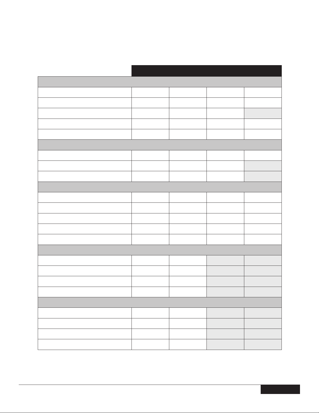
acoustic noisE EMission inforMation
COMPONENT TYPICAL CONFIGURATION HIGH-END CONFIGURATION
OPTIPLEX 755 MT
CPU E4500 E6850
Memory 1GB DDRII 667MHz 2GB DDRII 800MHz
HDD (#, capacity) 80GB 7200 RPM SATA 2 x 160GB 7200 RPM SATA
RMSD DVD/CD-RW Combo DVD/DVD+/-R
Graphics Adapter Integrated Adapter ATI 2400 Pro
The Declared Noise Emission in accordance with ISO 9296 for the Dell Optiplex 755 MT is as follows1: (all values L
bels2 ; 1 bel=10 decibels, re 10
OPERATING MODE
-12
Watts).
OPTIPLEX 755 MT
TYPICAL CONFIGURATION
DECLARED SOUND POWER (L
WAd
)
HIGH-END CONFIGURATION
DECLARED SOUND POWER (L
expressed in
WAd
WAd
)
Idle 3.7 3.8
HDD Operating 3.8 3.8
ODD Operating 5.0 5.0
90% CPU 3.7 4.1
1
All tests are conducted according to ISO 7779 and declared according to ISO 9296 except 90% CPU. For this mode, the system CPU was stressed at 90% utilization with no other
peripheral device actively seeking. This test mode is not specied in ISO 7779, but was measured using the same microphone distances and measurement techniques dened
for the other reported operating modes.
2
Declared Sound Power rounded to nearest tenth of a bel per ISO 9296 section 4.4.2
version 1.0 42
42
Page 43

DELL™ OPTIPLEX™ 755 TECHNICAL GUIDE
acoustic noisE EMission inforMation, cont.
The Declared A-weighted Sound Pressure Level in decibels (re 2x10⁻⁵ Pa), at Operator, Bystander, and Desk Side Positions are measured
in accordance with ISO 7779 7.6.1, 7.6.2, and C.15.2 and declared in accordance with ISO 9296 for this product is as follows1:
OPTIPLEX 755 MT
TYPICAL CONFIGURATION
DECLARED SOUND PRESSURE (LpA)
OPERATING
MODE
Idle 28 23 22 31 26 22
HDD Operating 29 24 22 31 26 22
ODD Operating 42 36 33 42 36 34
90% CPU 29 24 22 34 29 25
1
All tests are conducted according to ISO 7779 and declared according to ISO 9296 except 90% CPU. For this mode, the system CPU was stressed at 90% utilization with no other
peripheral device actively seeking. This test mode is not specied in ISO 7779, but was measured using the same microphone distances and measurement techniques dened
for the other reported operating modes.
Operator
Position
(LpA)
Bystander
Position
(LpA)
DeskSide
Position
(LpA)
HIGH-END CONFIGURATION
DECLARED SOUND PRESSURE (LpA)
Operator
Position
(LpA)
Bystander
Position
(LpA)
DeskSide
Position
(LpA)
version 1.0 43
43
Page 44

DELL™ OPTIPLEX™ 755 TECHNICAL GUIDE
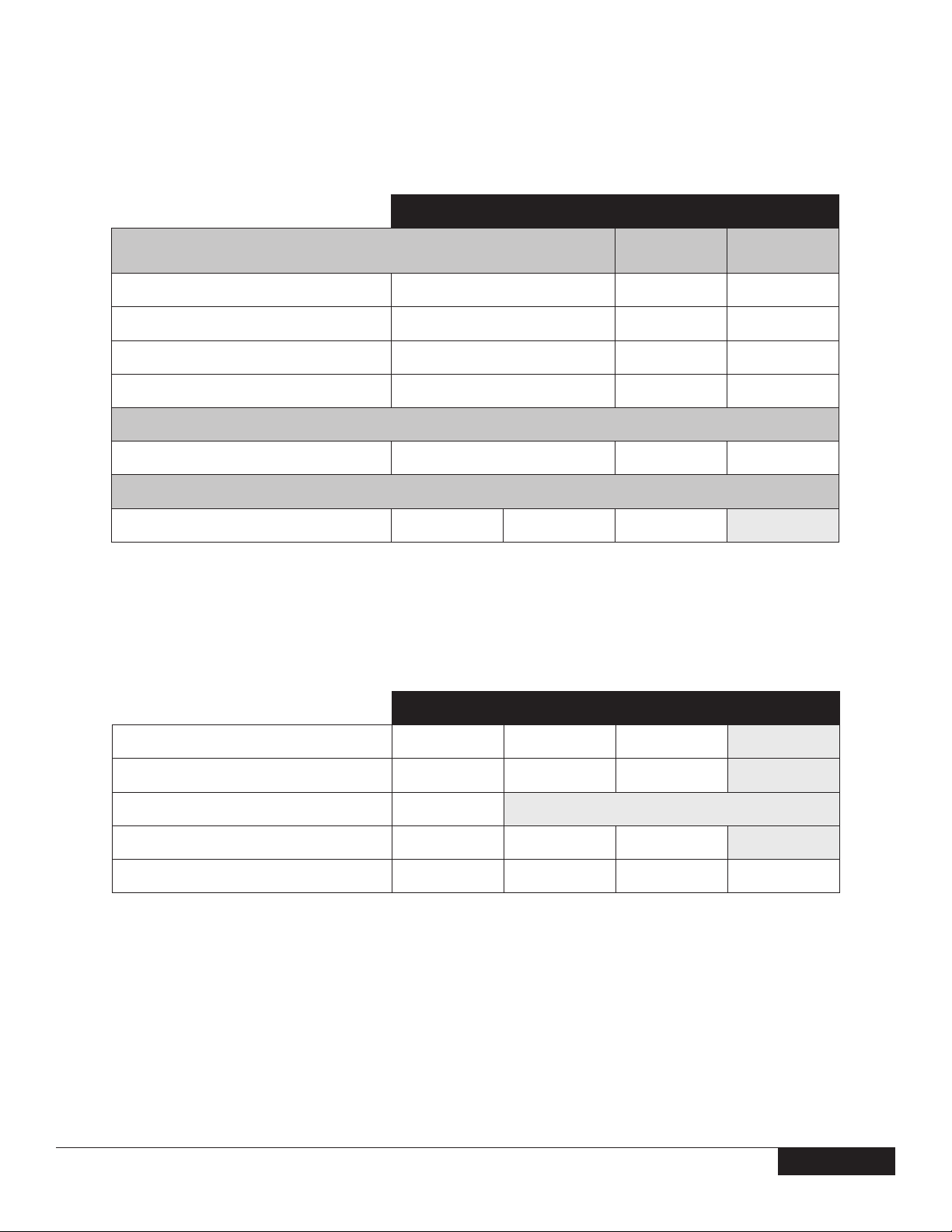
acoustic noisE EMission inforMation, cont.
COMPONENT TYPICAL CONFIGURATION HIGH-END CONFIGURATION
CPU E4500 E6850
Memory 1GB DDRII 667MHz 2GB DDRII 800MHz
HDD (#, capacity) 80GB 7200 RPM SATA 80GB 10,000 RPM SATA
RMSD DVD/CD-RW Combo DVD/CD-RW Combo
Graphics Adapter Integrated Adapter ATI 2400 Pro
OPTIPLEX 755 DT
The Declared Noise Emission in accordance with ISO 9296 for the Dell Optiplex 755 DT is as follows3: (all values L
bels4 ; 1 bel=10 decibels, re 10
OPERATING MODE
-12
Watts)
OPTIPLEX 755 DT
TYPICAL CONFIGURATION
DECLARED SOUND POWER (L
WAd
)
HIGH-END CONFIGURATION
DECLARED SOUND POWER (L
expressed in
WAd
WAd
)
Idle 3.7 4.0
HDD Operating 3.8 4.1
ODD Operating 5.2 5.1
90% CPU 3.7 4.4
The Declared A-weighted Sound Pressure Level in decibels (re 2x10⁻⁵ Pa), at Operator, Bystander, and Desk Side Positions are measured
in accordance with ISO 7779 7.6.1, 7.6.2, and C.15.2 and declared in accordance with ISO 9296 for this product is as follows3:
OPTIPLEX 755 DT
OPERATING MODE
TYPICAL CONFIGURATION
DECLARED SOUND PRESSURE (LpA)
Operator
Position
(LpA)
Bystander
Position
(LpA)
DeskSide
Position
(LpA)
HIGH-END CONFIGURATION
DECLARED SOUND PRESSURE (LpA)
Operator
Position
(LpA)
Bystander
Position
(LpA)
DeskSide
Position
(LpA)
Idle 27 22 23 32 27 24
HDD Operating 28 23 23 33 28 25
ODD Operating 43 37 36 42 38 33
90% CPU 27 22 22 36 31 27
3
All tests are conducted according to ISO 7779 and declared according to ISO 9296 except 90% CPU. For this mode, the system CPU was stressed at 90% utilization with no
other peripheral device spinning. This test mode is not specied in ISO 7779, but was measured using the same microphone distances and measurement techniques dened
for the other reported operating modes.
4
Declared Sound Power rounded to nearest tenth of a bel per ISO 9296 section 4.4.2
version 1.0 44
44
Page 45

DELL™ OPTIPLEX™ 755 TECHNICAL GUIDE
acoustic noisE EMission inforMation, cont.
COMPONENT TYPICAL CONFIGURATION HIGH-END CONFIGURATION
CPU E4500 E6850
Memory 1GB DDRII 667MHz 2GB DDRII 800MHz
HDD (#, capacity) 80GB 7200 RPM SATA 160GB 7200 RPM SATA
RMSD DVD/CD-RW Combo DVD/DVD+/-R
Graphics Adapter Integrated Adapter ATI 2400 Pro
OPTIPLEX 755 SFF
The Declared Noise Emission in accordance with ISO 9296 for the Dell Optiplex 755 SFF is as follows5: (all values L
-12
re 10
Watts)
OPTIPLEX 755 SFF
OPERATING MODE
TYPICAL CONFIGURATION
DECLARED SOUND POWER (L
WAd
)
WAd
expressed in bels6 ; 1 bel=10 decibels,
HIGH-END CONFIGURATION
DECLARED SOUND POWER (L
WAd
)
Idle 4.0 4.3
HDD Operating 4.1 4.3
ODD Operating 5.0 5.2
90% CPU 4.1 4.5
The Declared A-weighted Sound Pressure Level in decibels (re 2x10⁻⁵ Pa), at Operator, Bystander, and Desk Side Positions are measured in accordance
with ISO 7779 7.6.1, 7.6.2, and C.15.2 and declared in accordance with ISO 9296 for this product is as follows5:
OPTIPLEX 755 SFF
OPERATING MODE
TYPICAL CONFIGURATION
DECLARED SOUND PRESSURE (LpA)
Operator
Position
(LpA)
Bystander
Position
(LpA)
DeskSide
Position
(LpA)
HIGH-END CONFIGURATION
DECLARED SOUND PRESSURE (LpA)
Operator
Position
(LpA)
Bystander
Position
(LpA)
DeskSide
Position
(LpA)
Idle 31 26 26 35 31 26
HDD Operating 31 26 26 35 31 26
ODD Operating 38 33 30 44 39 33
90% CPU 32 27 27 36 32 28
5
All tests are conducted according to ISO 7779 and declared according to ISO 9296 except 90% CPU. For this mode, the system CPU was stressed at 90% utilization with no
other peripheral device spinning. This test mode is not specied in ISO 7779, but was measured using the same microphone distances and measurement techniques dened
for the other reported operating modes.
6
Declared Sound Power rounded to nearest tenth of a bel per ISO 9296 section 4.4.2
version 1.0 45
45
 Loading...