

Page 1

Dell™ OptiPlex™ 745c
Quick Reference Guide
Model DCSM
www.dell.com | support.dell.com
Page 2

Notes, Notices, and Cautions
NOTE: A NOTE indicates important information that helps you make better use of your computer.
NOTICE: A NOTICE indicates potential damage to hardware or loss of data and tells you how to avoid the problem.
CAUTION: A CAUTION indicates a potential for property damage, personal injury, or death.
If you purchased a Dell™ n Series computer, any references in this document to Microsoft® Windows®
operating systems are not applicable.
____________________
Information in this document is subject to change without notice.
© 2007 Dell Inc. All rights reserved.
Reproduction in any manner whatsoever without the written permission of Dell Inc. is strictly forbidden.
Trademarks used in this text: Dell, the DELL logo, and OptiPlex are trademarks of Dell Inc.; Intel is registered trademarks of Intel Corporation;
Microsoft, Windows, and Vista are registered trademarks of Microsoft Corporation.
Other trademarks and trade names may be used in this document to refer to either the entities claiming the marks and names or their products.
Dell Inc. disclaims any proprietary interest in trademarks and trade names other than its own.
Model DCSM
February 2007 P/N PJ179 Rev. A00
Page 3

Contents
Finding Information . . . . . . . . . . . . . . . . . . . . . . . . . . . . . . . . 5
System Views
Mini Tower Computer — Front View
Mini Tower Computer — Back View
. . . . . . . . . . . . . . . . . . . . . . . . . . . . . . . . . . . 8
. . . . . . . . . . . . . . . . . . . . . 8
. . . . . . . . . . . . . . . . . . . . 10
Mini Tower Computer — Back-Panel Connectors
Removing the Computer Cover
Before You Begin
Mini Tower Computer
Inside Your Computer
Mini Tower Computer
Setting Up Your Computer
Set Up Your Keyboard and Mouse
Set Up Your Monitor
Power Connections
Solving Problems
Dell Diagnostics
System Lights
. . . . . . . . . . . . . . . . . . . . . . . . . . . . . . . . 21
. . . . . . . . . . . . . . . . . . . . . . . . . . . . . . . 21
. . . . . . . . . . . . . . . . . . . . . . . . . . . . . . . . 24
Diagnostic Lights
Beep Codes
. . . . . . . . . . . . . . . . . . . . . . . . . . . . . . . . . 27
. . . . . . . . . . . . . . . . . . . . . . . . . . 13
. . . . . . . . . . . . . . . . . . . . . . . . . . . . . . 13
. . . . . . . . . . . . . . . . . . . . . . . . . . . . 14
. . . . . . . . . . . . . . . . . . . . . . . . . . . . . . 16
. . . . . . . . . . . . . . . . . . . . . . . . . . . . 16
. . . . . . . . . . . . . . . . . . . . . . . . . . . . 19
. . . . . . . . . . . . . . . . . . . . . 20
. . . . . . . . . . . . . . . . . . . . . . . . . . . . 20
. . . . . . . . . . . . . . . . . . . . . . . . . . . . . 21
. . . . . . . . . . . . . . . . . . . . . . . . . . . . . . 25
Resolving Software and Hardware Incompatibilities
Using Microsoft Windows XP System Restore
Reinstalling Microsoft Windows XP
Microsoft
®
Windows Vista™. . . . . . . . . . . . . . . . . . . . . . . . 32
. . . . . . . . . . . . . . . . . . . . 30
. . . . . . . . . . . . . 11
. . . . . . . . . . . 28
. . . . . . . . . . . . . . . 28
The support.dell.com user interface may vary depending
on your selections.
Using the Drivers and Utilities CD
Drivers for Your Computer
. . . . . . . . . . . . . . . . . . . . . . . . . . . . . . . . 34
. . . . . . . . . . . . . . . . . . . . . . . . 34
. . . . . . . . . . . . . . . . . . . . . . . . . 34
Index . . . . . . . . . . . . . . . . . . . . . . . . . . . . . . . . . . . . . . . . . 35
Contents 3
Page 4

4 Contents
Page 5

Finding Information
NOTE: Some features or media may be optional and may not ship with your computer. Some features or media may
not be available in certain countries.
NOTE: Additional information may ship with your computer.
What Are You Looking For? Find It Here
• A diagnostic program for my computer
• Drivers for my computer
• My computer documentation
• My device documentation
• Desktop System Software (DSS)
• How to remove and replace parts
• Specifications
• How to configure system settings
• How to troubleshoot and solve problems
Drivers and Utilities CD (ResourceCD)
NOTE: The Drivers and Utilities CD may be optional
and may not ship with your computer.
Documentation and drivers are already installed on
your computer. You can use the CD to reinstall
drivers (see "Using the Drivers and Utilities CD" on
page 34), run the Dell Diagnostics (see "Dell
Diagnostics" on page 21), or access your
documentation.
Readme files may
be included on your
CD to provide lastminute updates
about technical
changes to your
computer or
advanced technical
reference material
for technicians or
experienced users.
NOTE: Drivers and documentation updates can be
found at support.dell.com.
Dell™ OptiPlex™ User’s Guide
Microsoft Windows XP Help and Support Center
1
Click
Start→
Help and Support→ Dell User and
→
System Guides
2
Click the
The User’s Guide is also available on the optional
Drivers and Utilities CD.
User’s Guide
System Guides
for your computer.
.
Quick Reference Guide 5
Page 6

What Are You Looking For? Find It Here
• Warranty information
Dell™ Product Information Guide
• Terms and Conditions (U.S. only)
• Safety instructions
• Regulatory information
• Ergonomics information
• End User License Agreement
• How to reinstall my operating system
• How to use Windows XP
• How to work with programs and files
• How to personalize my desktop
Operating System CD
NOTE: The Operating System CD may be optional and
may not ship with your computer.
The operating system is already installed on your
computer. To reinstall your operating system, use
the Operating System CD (see "Reinstalling
Microsoft Windows XP" on page 30).
After you reinstall
your operating
system, use the
optional Drivers and
Utilities CD
(ResourceCD) to
reinstall drivers for
the devices that
came with your
computer. For more
information, see
"Drivers and Utilities CD (ResourceCD)" on page 5.
Your operating system product key label is located
on your computer (see "Service Tag and Microsoft®
Windows® Product Key" on page 7).
NOTE: The color of your Operating System CD varies
according to the operating system you ordered.
Windows Help and Support Center
1
Click
Start→
Help and Support
2
Type a word or phrase that describes your problem
and click the arrow icon.
3
Click the topic that describes your problem.
4
Follow the instructions on the screen.
.
6 Quick Reference Guide
Page 7

What Are You Looking For? Find It Here
• Service Tag and Express Service Code
• Microsoft Windows Product Key Label
Service Tag and Microsoft® Windows® Product Key
These labels are located on your computer.
• Use the Service
Tag to identify
your computer
when you use
support.dell.co
or contact
m
support.
• Enter the Express Service Code to direct your call
when contacting support.
• Solutions — Troubleshooting hints and tips, articles
from technicians, online courses, and frequently asked
questions
Dell Support Website — support.dell.com
NOTE: Select your region or business segment to
view the appropriate support site.
• Community — Online discussion with other Dell
customers
• Upgrades — Upgrade information for components, such
as the memory, hard drive, and operating system
• Customer Care — Contact information, service call and
order status, and warranty and repair information
• Service and support — Service call status, support
history, service contract, and online discussions with
support
• Reference — Computer documentation, details on my
computer configuration, product specifications, and
white papers
• Downloads — Certified drivers, patches, and software
updates
• Desktop System Software (DSS)— If you reinstall the
operating system on your computer, you should also
reinstall the DSS utility. DSS automatically detects your
computer and operating system and installs the updates
appropriate for your configuration, providing critical
updates for your operating system and support for Dell™
3.5-inch USB floppy drives, Intel
®
processors, optical
drives, and USB devices. DSS is necessary for correct
operation of your Dell computer.
To download Desktop System Software:
1
Go to
support.dell.com
business segment, then enter your Service Tag.
2
Select
3
Click your operating system, and then search for
the keyword
NOTE: The support.dell.com user interface may vary
depending on your selections.
, select your region or
Drivers & Downloads
Desktop System Software
, then click Go.
.
Quick Reference Guide 7
Page 8
System Views
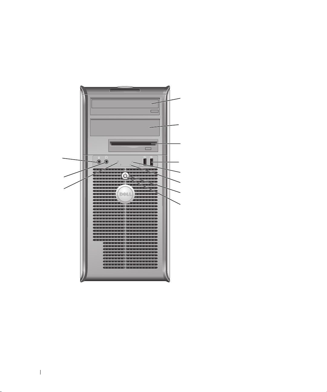
Mini Tower Computer — Front View
1
2
3
11
10
9
4
5
6
7
8
8 Quick Reference Guide
Page 9

1 5.25-inch drive bay Can contain an optical drive. Insert a CD or DVD (if supported) into this drive.
2 5.25-inch drive bay Can contain an optical drive. Insert a CD or DVD (if supported) into this drive.
3 3.5-inch drive bay Can contain an optional floppy drive or optional media card reader.
4 USB 2.0 connectors (2) Use the front USB connectors for devices that you connect occasionally, such as
joysticks or cameras, or for bootable USB devices (see your online User’s Guide
for more information on booting to a USB device).
It is recommended that you use the back USB connectors for devices that
typically remain connected, such as printers and keyboards.
5 LAN indicator light This light indicates that a LAN (local area network) connection is established.
6 diagnostic lights Use the lights to help you troubleshoot a computer problem based on the
diagnostic code. For more information, see "Diagnostic Lights" on page 25.
7 power button Press this button to turn on the computer.
NOTICE: To avoid losing data, do not turn off the computer by pressing the
power button. Instead, perform an operating system shutdown. See "Before
You Begin" on page 13 for more information.
NOTICE: If your operating system has ACPI enabled, when you press the
power button the computer will perform an operating system shutdown.
8 power light The power light illuminates and blinks or remains solid to indicate different
operating modes:
• No light — The computer is turned off.
• Steady green — The computer is in a normal operating state.
• Blinking green — The computer is in a power-saving mode.
• Blinking or solid amber — See
To exit from a power-saving mode, press the power button or use the keyboard or
the mouse if it is configured as a wake device in the Windows Device Manager.
For more information about sleep modes and exiting from a power-saving mode,
see your online User’s Guide.
See "System Lights" on page 24 for a description of light codes that can help you
troubleshoot problems with your computer.
9 hard-drive activity light This light flickers when the hard drive is being accessed.
10 headphone connector Use the headphone connector to attach headphones and most kinds of speakers.
11 microphone connector Use the microphone connector to attach a microphone.
your online User’s Guide
.
Quick Reference Guide 9
Page 10
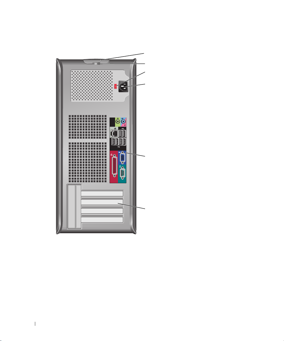
Mini Tower Computer — Back View
1
2
3
4
5
10 Quick Reference Guide
6
Page 11
1 cover-release latch This latch allows you to open the computer cover.
2 padlock ring Insert a padlock to lock the computer cover.
3 voltage selection switch Your computer is equipped with a manual voltage-selection switch.
To help avoid damaging a computer with a manual voltage-selection switch, set
the switch for the voltage that most closely matches the AC power available in
your location.
NOTICE: The voltage selection switch must be set to the 115-V position even
though the AC power available in Japan is 100 V.
Also, ensure that your monitor and attached devices are electrically rated to
operate with the AC power available in your location.
4 power connector Insert the power cable.
5 back-panel connectors Plug serial, USB, and other devices into the appropriate connectors (see "Mini
Tower Computer — Back-Panel Connectors" on page 11).
6 card slots Access connectors for any installed PCI and PCI Express cards.
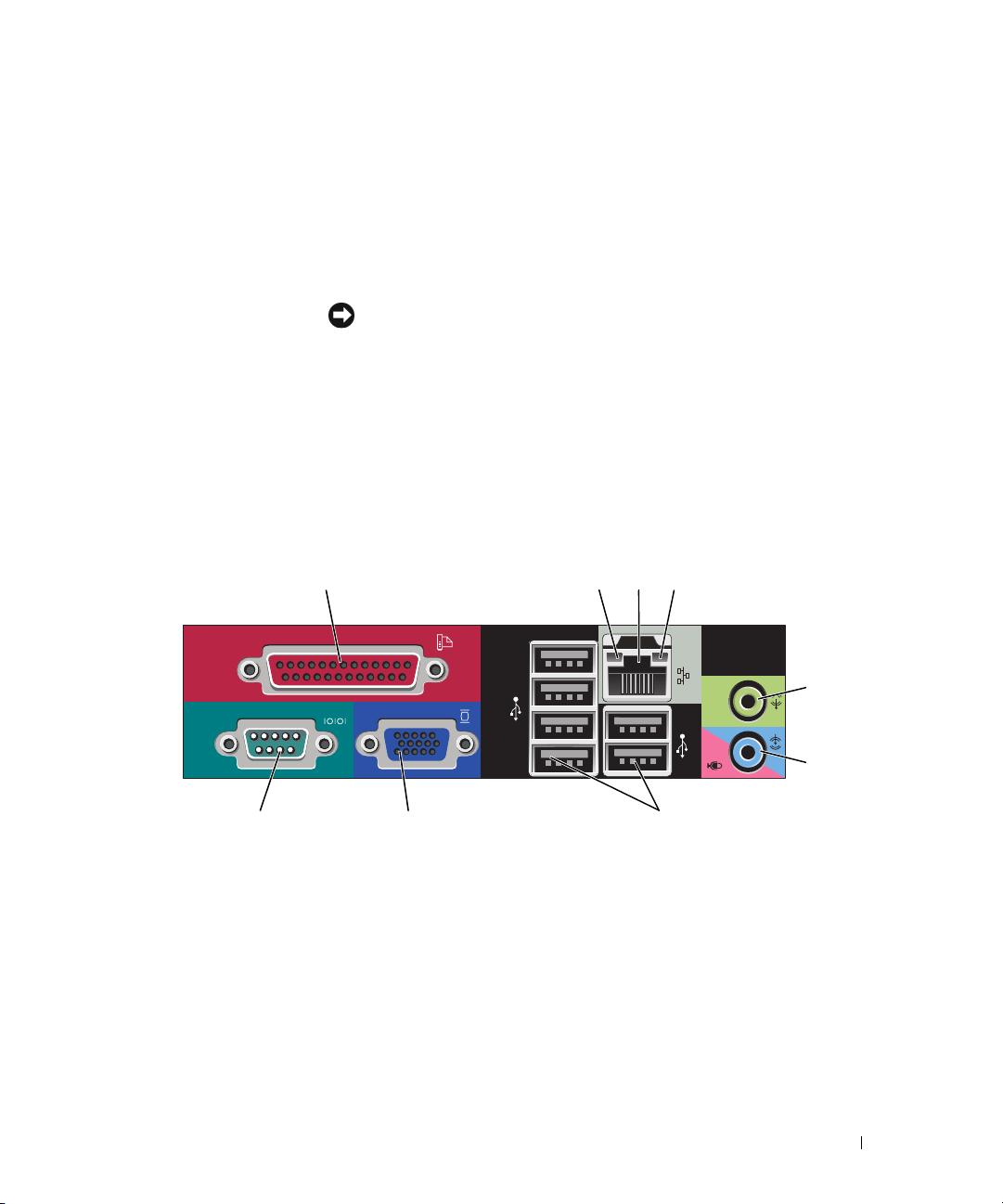
Mini Tower Computer — Back-Panel Connectors
13
98 7
24
5
6
Quick Reference Guide 11
Page 12

1 parallel connector Connect a parallel device, such as a printer, to the parallel connector. If you have a
USB printer, plug it into a USB connector.
NOTE: The integrated parallel connector is automatically disabled if the computer
detects an installed card containing a parallel connector configured to the same
address. For more information, see your online User’s Guide.
2 link integrity light
3 network adapter
connector
• Green — A good connection exists between a 10-Mbps network and the
computer.
• Orange — A good connection exists between a 100-Mbps network and the
computer.
• Yellow — A good connection exists between a 1-Gbps (or 1000-Mbps) network
and the computer.
• Off — The computer is not detecting a physical connection to the network.
To attach your computer to a network or broadband device, connect one end of a
network cable to either a network jack or your network or broadband device.
Connect the other end of the network cable to the network adapter connector on
the back panel of your computer. A click indicates that the network cable has been
securely attached.
NOTE: Do not plug a telephone cable into the network connector.
On computers with a network connector card, use the connector on the card.
It is recommended that you use Category 5 wiring and connectors for your
network. If you must use Category 3 wiring, force the network speed to 10 Mbps to
ensure reliable operation.
4 network activity light Flashes a yellow light when the computer is transmitting or receiving network
data. A high volume of network traffic may make this light appear to be in a steady
"on" state.
5 line-out connector Use the green line-out connector to attach most speakers with integrated
amplifiers.
6 line-in/microphone
connector
7 USB 2.0 connectors (6) Use the back USB connectors for devices that typically remain connected, such as
8 video connector Plug the cable from your VGA-compatible monitor into the blue connector.
Use the blue and pink line-in/microphone connector to attach a record/playback
device such as a cassette player, CD player, or VCR.; or a personal computer
microphone for voice or musical input into a sound or telephony program.
printers and keyboards.
NOTE: If you purchased an optional graphics card, this connector will be covered by
a cap. Connect your monitor to the connector on the graphics card. Do not remove
the cap.
NOTE: If you are using a graphics card that supports dual monitors, use the y-cable
that came with your computer.
9 serial connector Connect a serial device, such as a handheld device, to the serial port. The default
designations are COM1 for serial connector 1 and COM2 for serial connector 2.
For more information, see your online User’s Guide.
12 Quick Reference Guide
Page 13

Removing the Computer Cover
CAUTION: Before you begin any of the procedures in this section, follow the safety instructions in the
Product Information Guide.
CAUTION: To guard against electrical shock, always unplug your computer from the electrical outlet before
removing the cover.
Before You Begin
NOTICE: To avoid losing data, save and close any open files and exit any open programs before you turn off
your computer.
1
Shut down the operating system:
a
Save and close any open files, exit any open programs, click the
Turn Off Computer
b
In the
Turn off computer
.
window, click
Tur n o ff
.
The computer turns off after the operating system shutdown process finishes.
2
Ensure that the computer and any attached devices are turned off. If your computer and attached
devices did not automatically turn off when you shut down your operating system, turn them off now.
Before Working Inside Your Computer
Use the following safety guidelines to help protect your computer from potential damage and to help
ensure your own personal safety.
CAUTION: Before you begin any of the procedures in this section, follow the safety instructions in the
Product Information Guide.
Start
button, and then click
CAUTION: Handle components and cards with care. Do not touch the components or contacts on a card. Hold a
card by its edges or by its metal mounting bracket. Hold a component such as a processor by its edges, not by
its pins.
NOTICE: Only a certified service technician should perform repairs on your computer. Damage due to servicing
that is not authorized by Dell is not covered by your warranty.
NOTICE: When you disconnect a cable, pull on its connector or on its strain-relief loop, not on the cable itself.
Some cables have a connector with locking tabs; if you are disconnecting this type of cable, press in on the locking
tabs before you disconnect the cable. As you pull connectors apart, keep them evenly aligned to avoid bending any
connector pins. Also, before you connect a cable, ensure that both connectors are correctly oriented and aligned.
To avoid damaging the computer, perform the following steps before you begin working inside the
computer.
1
Turn off your computer.
NOTICE: To disconnect a network cable, first unplug the cable from your computer and then unplug it from the
network wall jack.
2
Disconnect any telephone or telecommunication lines from the computer.
Quick Reference Guide 13
Page 14

3
Disconnect your computer and all attached devices from their electrical outlets, and then press the
power button to ground the system board.
4
If applicable, remove the computer stand (for instructions, see the documentation that came with the
stand).
CAUTION: To guard against electrical shock, always unplug your computer from the electrical outlet before
removing the cover.
5
Remove the computer cover. See "Mini Tower Computer" on page 14.
NOTICE: Before touching anything inside your computer, ground yourself by touching an unpainted metal surface,
such as the metal at the back of the computer. While you work, periodically touch an unpainted metal surface to
dissipate any static electricity that could harm internal components.
Mini Tower Computer
CAUTION: Before you begin any of the procedures in this section, follow the safety instructions in the
Product Information Guide.
CAUTION: To guard against electrical shock, always unplug your computer from the electrical outlet before
removing the computer cover.
1
Follow the procedures in "Before You Begin" on page 13.
2
Lay the computer on its side as shown in the illustration.
3
Locate the cover release latch shown in the illustration. Then, slide the release latch back as you lift the
cover.
4
Grip the sides of the computer cover and pivot the cover up using the hinge tabs as leverage points.
5
Remove the cover from the hinge tabs and set it aside on a soft nonabrasive surface.
CAUTION: Graphic card heatsinks may become very hot during normal operation. Ensure that a graphic card
heatsink has had sufficient time to cool before you touch it.
14 Quick Reference Guide
Page 15

1
2
3
1 security cable slot 2 cover release latch 3 padlock ring
Quick Reference Guide 15
Page 16
Inside Your Computer
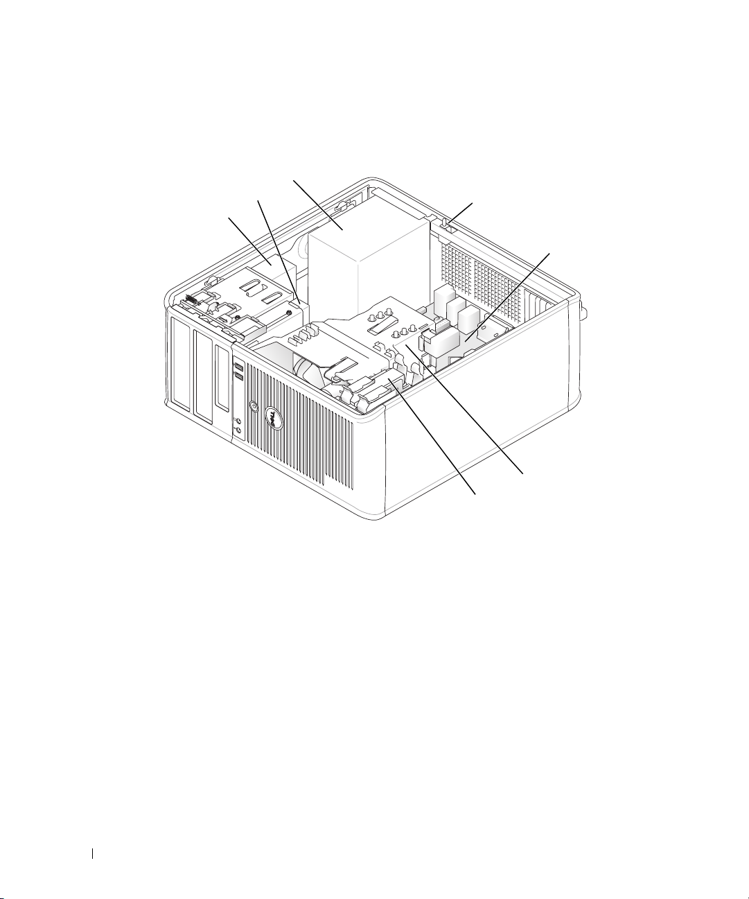
Mini Tower Computer
2
1
3
4
5
6
7
1 optical drive 2 floppy drive 3 power supply
4 chassis-intrusion switch 5 system board 6 heat-sink assembly
7 hard drive
16 Quick Reference Guide
Page 17
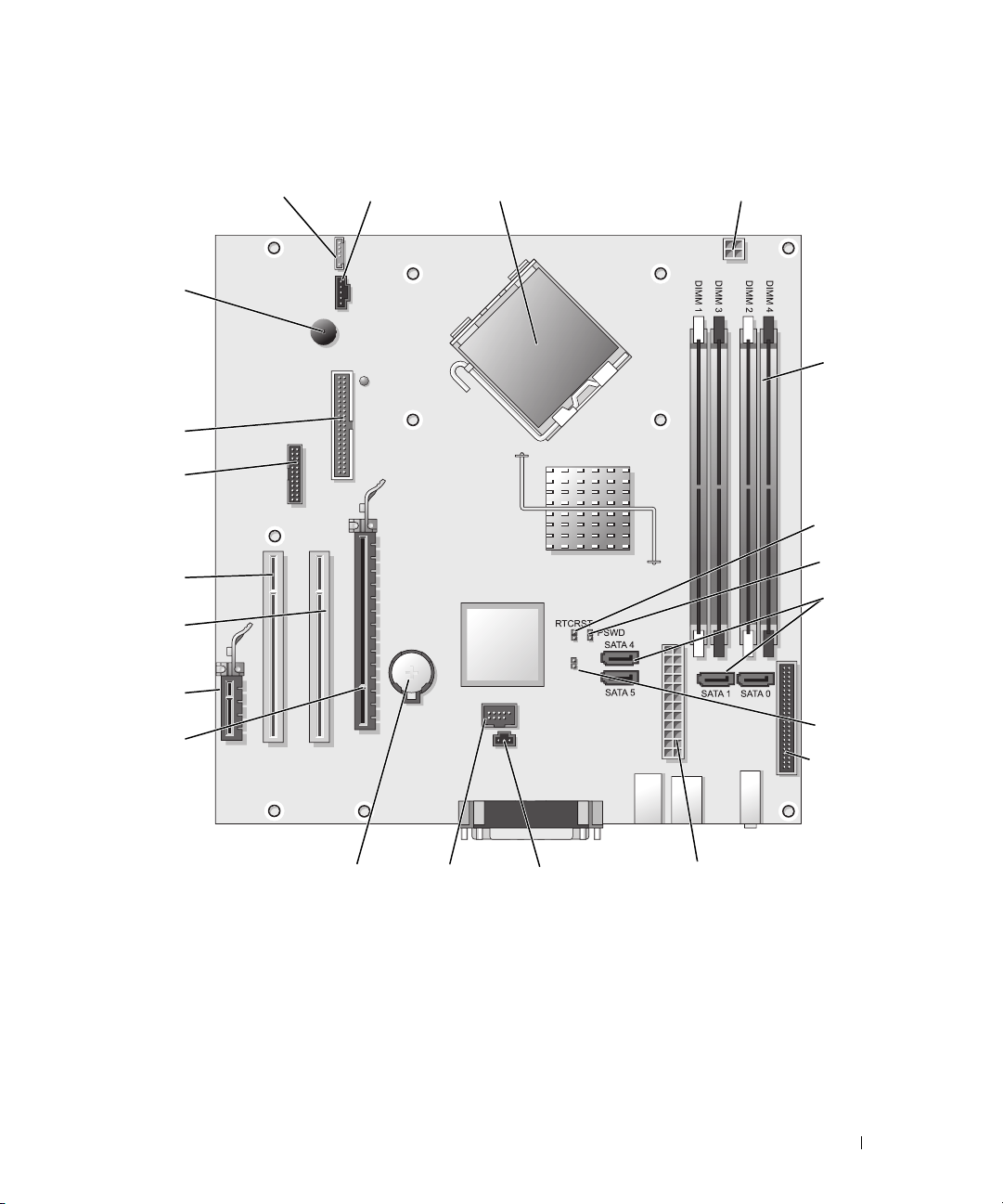
System Board Components
21
1
2
3
20
4
19
18
5
6
17
7
16
MFG_MODE
15
14
8
9
13
12
11
10
Quick Reference Guide 17
Page 18
1 fan connector (FAN) 12 internal USB (INTERNAL_USB)
2 processor connector (CPU) 13 battery socket (BATT)
3 processor power connector (12VPOWER) 14 PCI Express x16 connector (SLOT1)
4 memory module connectors (DIMM_1, DIMM_2,
DIMM_3, DIMM_4)
5 RTC reset jumper (RTCRST) 16 PCI connector (SLOT2)
6 password jumper (PSWD) 17 PCI connector (SLOT3)
7 SATA drive connectors (SATA0, SATA1, SATA4, SATA5) 18 serial connector (SER2)
8 manufacturing mode jumper (MFG_MODE) 19 floppy drive connector (DSKT)
9 front-panel connector (FNT_PANEL) 20 system board speaker (BEEP)
10 power connector (POWER) 21 speaker connector (INT_SPKR)
11 intrusion switch connector (INTRUDER)
15 PCI Express x1 connector (SLOT4)
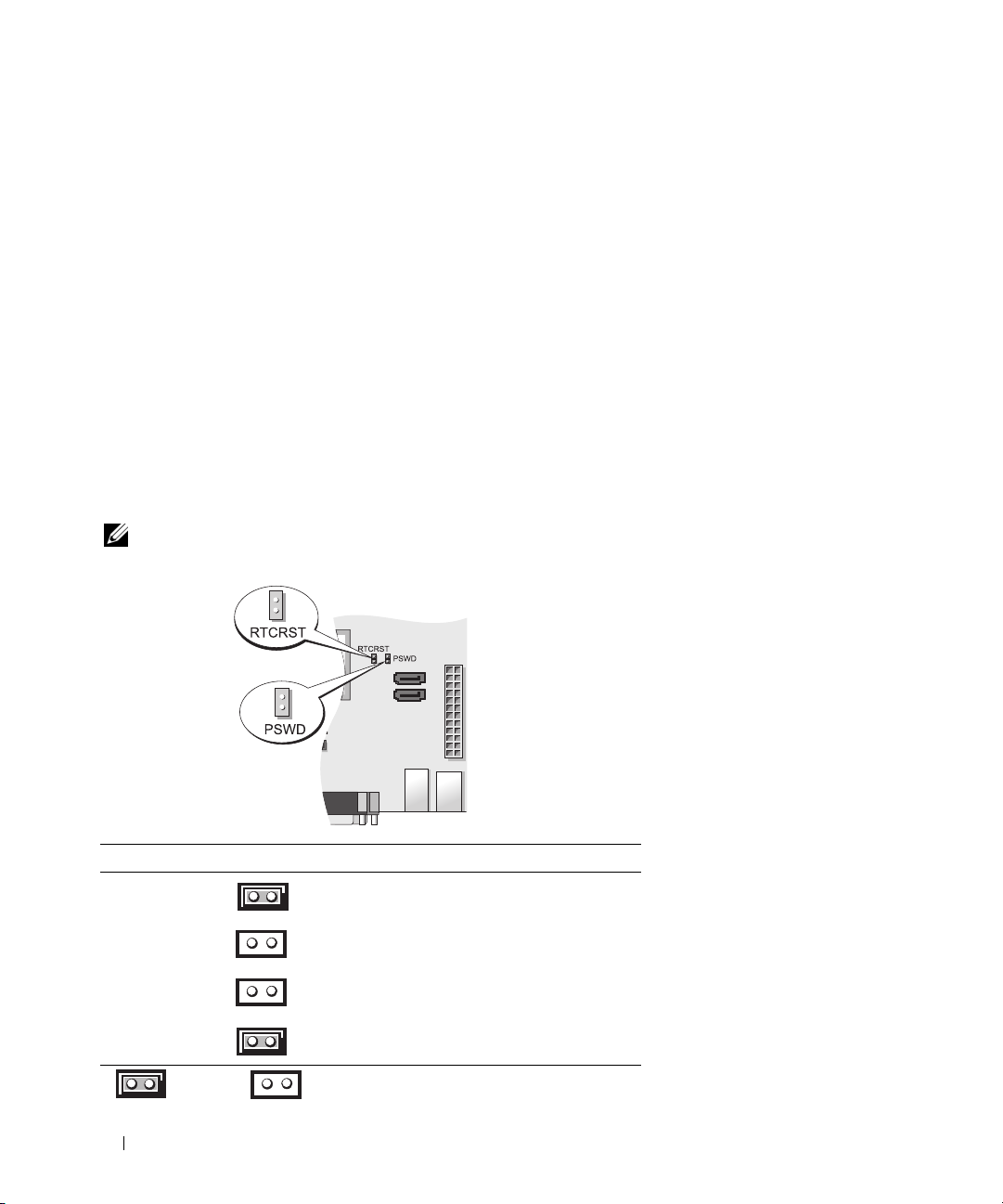
Jumper Settings
NOTE: Do not populate the MFG_MODE jumper. Active Management technology will not function properly. Only
manufacturing uses this jumper.
Jumper Setting Description
PSWD Password features are enabled
(default setting).
Password features are
disabled.
RTCRST The real-time clock has
not been reset.
jumpered unjumpered
The real-time clock is being reset
(jumpered temporarily).
18 Quick Reference Guide
Page 19

Setting Up Your Computer
CAUTION: Before performing any of the procedures in this section, follow the safety instructions in
Product Information Guide.
NOTICE: If your computer has an expansion card installed (such as a modem card), connect the appropriate cable
to the card, not to the connector on the back panel.
NOTICE: To help allow the computer to maintain proper operating temperature, ensure that you do not place the
computer too close to a wall or other storage compartment that might prevent air circulation around the chassis.
See your Product Information Guide for more information.
NOTE: Before you install any devices or software that did not ship with your computer, read the documentation
that came with the device or software, or contact the vendor to verify that the device or software is compatible
with your computer and operating system.
You must complete all the steps to properly set up your computer. See the appropriate figures that follow
the instructions.
NOTICE: Do not attempt to operate a PS/2 mouse and a USB mouse simultaneously.
1
Connect the keyboard and mouse.
NOTICE: Do not connect a modem cable to the network adapter connector. Voltage from telephone
communications can cause damage to the network adapter
2
Connect the modem or network cable.
Insert the network cable, not the telephone line, into the network connector. If you have an optional
modem, connect the telephone line to the modem.
3
Connect the monitor.
Align and gently insert the monitor cable to avoid bending connector pins. Tighten the thumbscrews
on the cable connectors.
NOTE: Some monitors have the video connector underneath the back of the screen. See the documentation
that came with your monitor for its connector locations.
4
Connect the speakers.
5
Connect power cables to the computer, monitor, and devices and connect the other ends of the power
cables to electrical outlets.
NOTICE: To avoid damaging a computer with a manual voltage-selection switch, set the switch for the voltage that
most closely matches the AC power available in your location.
NOTICE: In Japan, the voltage selection switch must be set to the 115-V position even though the AC power
available in Japan is 100 V.
6
Verify that the voltage selection switch is set correctly for your location.
Your computer has a manual voltage-selection switch. Computers with a voltage selection switch on
the back panel must be manually set to operate at the correct operating voltage.
Quick Reference Guide 19
Page 20
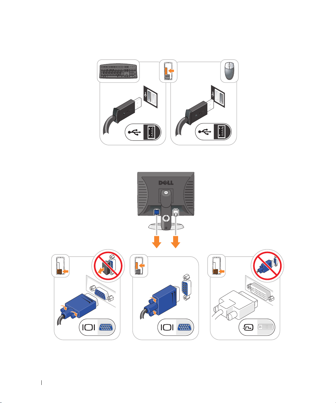
Set Up Your Keyboard and Mouse
Set Up Your Monitor
20 Quick Reference Guide
Page 21
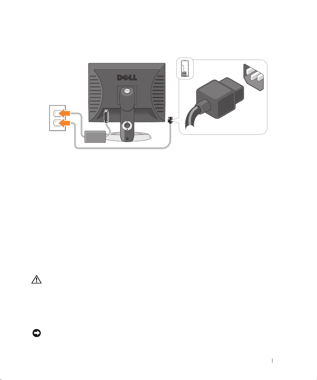
Power Connections
Solving Problems
Dell provides a number of tools to help you if your computer does not perform as expected. For the latest
troubleshooting information available for your computer, see the Dell Support website at
support.dell.com.
If computer problems occur that require help from Dell, write a detailed description of the error, beep
codes, or diagnostics light patterns, record your Express Service Code and Service Tag below, and then
contact Dell from the same location as your computer. For information on contacting Dell, see your
online User’s Guide.
For an example of the Express Service Code and Service Tag, see "Finding Information" in your computer
User’s Guide.
Express Service Code: ___________________________
Service Tag: ___________________________
Dell Diagnostics
CAUTION: Before you begin any of the procedures in this section, follow the safety instructions in the
Product Information Guide.
When to Use the Dell Diagnostics
If you experience a problem with your computer, perform the checks in "Solving Problems" in your online
User’s Guide and run the Dell Diagnostics before you contact Dell for technical assistance. For
information on contacting Dell, see your online User’s Guide.
NOTICE: The Dell Diagnostics works only on Dell™ computers.
Quick Reference Guide 21
Page 22

Enter system setup (see "System Setup" in your online User’s Guide for instructions), review your
computer’s configuration information, and ensure that the device you want to test displays in system
setup and is active.
Start the Dell Diagnostics from either your hard drive or from the optional Drivers and Utilities CD
(ResourceCD).
Starting the Dell Diagnostics From Your Hard Drive
1
Turn on (or restart) your computer.
2
When the DELL logo appears, press <F12> immediately.
NOTE: If you see a message stating that no diagnostics utility partition has been found, run the Dell
Diagnostics from the optional Drivers and Utilities CD (see "Starting the Dell Diagnostics From the Drivers and
Utilities CD" on page 22).
If you wait too long and the operating system logo appears, continue to wait until you see the
Microsoft
®
Windows® desktop. Then shut down your computer and try again.
When the boot device list appears, highlight
3
When the Dell Diagnostics
Starting the Dell Diagnostics From the Drivers and Utilities CD
1
Insert the
2
Shut down and restart the computer.
Drivers and Utilities
Main Menu
CD.
Boot to Utility Partition
appears, select the test you want to run.
and press <Enter>.
When the DELL logo appears, press <F12> immediately.
If you wait too long and the operating system logo appears, continue to wait until you see the
Microsoft Windows desktop. Then shut down your computer and try again.
NOTE: The next steps change the boot sequence for one time only. On the next start-up, the computer boots
according to the devices specified in system setup.
3
When the boot device list appears, highlight the listing for the CD/DVD drive and press <Enter>.
4
Select the listing for the CD/DVD drive option from the CD boot menu.
5
Select the option to boot from the CD/DVD drive from the menu that appears.
6
Ty p e 1 to start the
7
Ty p e 2 to start the Dell Diagnostics.
8
Select
Run the 32 Bit Dell Diagnostics
Drivers and Utilities
CD menu.
from the numbered list. If multiple versions are listed, select
the version appropriate for your computer.
9
When the Dell Diagnostics
Main Menu
appears, select the test you want to run.
22 Quick Reference Guide
Page 23

Dell Diagnostics Main Menu
1
After the Dell Diagnostics loads and the
Main Menu
screen appears, click the button for the option
you want.
Option Function
Express Test Performs a quick test of devices. This test typically takes 10 to 20 minutes and
requires no interaction on your part. Run Express Test first to increase the
possibility of tracing the problem quickly.
Extended Test Performs a thorough check of devices. This test typically takes an hour or more
and requires you to answer questions periodically.
Custom Test Tests a specific device. You can customize the tests you want to run.
Symptom Tree Lists the most common symptoms encountered and allows you to select a test
based on the symptom of the problem you are having.
2
If a problem is encountered during a test, a message appears with an error code and a description of the
problem. Write down the error code and problem description and follow the instructions on the
screen.
If you cannot resolve the error condition, contact Dell. For information on contacting Dell, see your
online
User’s Guide
NOTE: The Service Tag for your computer is located at the top of each test screen. If you contact Dell,
technical support will ask for your Service Tag.
3
If you run a test from the
.
Custom Test
or
Symptom Tree
option, click the applicable tab described in
the following table for more information.
Tab Function
Results Displays the results of the test and any error conditions encountered.
Errors Displays error conditions encountered, error codes, and the problem
description.
Help Describes the test and may indicate requirements for running the test.
Configuration Displays your hardware configuration for the selected device.
The Dell Diagnostics obtains configuration information for all devices from
system setup, memory, and various internal tests, and it displays the
information in the device list in the left pane of the screen. The device list may
not display the names of all the components installed on your computer or all
devices attached to your computer.
Parameters You can customize the test by changing the test settings.
Quick Reference Guide 23
Page 24

4
When the tests are completed, if you are running the Dell Diagnostics from the
CD (optional), remove the CD.
5
Close the test screen to return to the
computer, close the
Main Menu
Main Menu
screen.
screen. To exit the Dell Diagnostics and restart the
System Lights
Your power light may indicate a computer problem.
Power Light Problem Description Suggested Resolution
Solid green Power is on, and the computer is
operating normally.
Blinking green The computer is in a power-saving
mode.
Blinks green several
times and then
turns off
Solid yellow A device on the system board may be
Blinking yellow A power supply or system board
Solid green and a
beep code during
POST
Solid green power
light, no beep code
and no video during
POST
Solid green power
light and no beep
code, but the
computer locks up
during POST
A configuration error exists. Check Diagnostic Lights to see if the specific problem
faulty or incorrectly installed or the
voltage selection switch on the power
supply may be set incorrectly.
failure has occurred.
A problem was detected while the
BIOS was executing.
The monitor or the graphics card may
be faulty or incorrectly installed.
An integrated system board device
may be faulty.
No corrective action is required.
Press the power button, move the mouse, or press a
key on the keyboard to wake the computer.
is identified (see "Diagnostic Lights" on page 25).
Check Diagnostic Lights to see if the specific problem
is identified (see "Diagnostic Lights" on page 25).
See "Power Problems" in your online User’s Guide.
If the computer does not boot, contact Dell for
technical assistance.
Dell, see your online
Check Diagnostic Lights to see if the specific problem
is identified (see "Diagnostic Lights" on page 25).
See "Power Problems" in your online User’s Guide.
If the computer does not boot, contact Dell for
technical assistance.
Dell, see your online
For instructions on diagnosing the beep code see
"Beep Codes" on page 27. Also, check Diagnostic
Lights to see if the specific problem is identified.
Check Diagnostic Lights to see if the specific problem
is identified.
Check Diagnostic Lights to see if the specific problem
is identified. If the problem is not identified, contact
Dell for technical assistance.
contacting Dell, see your online
Drivers and Utilities
For information on contacting
User’s Guide
For information on contacting
User’s Guide
.
.
For information on
User’s Guide
.
24 Quick Reference Guide
Page 25

Diagnostic Lights
CAUTION: Before you begin any of the procedures in this section, follow the safety instructions in the
Product Information Guide.
To help you troubleshoot a problem, your computer has four lights labeled "1," "2," "3," and "4" on the
front or back panel. The lights can be "off" or green. When the computer starts normally, the patterns or
codes on the lights change as the boot process completes. If the POST portion of system boot completes
successfully, all four lights display solid green for a short time, and then turn off.
If the computer malfunctions during the POST process, the pattern displayed on the LEDs may help
identify where in the process the computer halted. If the computer malfunctions after a successful
POST, the diagnostic lights do not indicate the cause of the problem.
NOTE: The orientation of the diagnostic lights may vary depending on the system type. The diagnostic lights can be
either vertically or horizontally oriented.
Light Pattern Problem Description Suggested Resolution
The computer is in a normal "off" condition, or a
possible pre-BIOS failure has occurred.
The diagnostic lights are not lit after the computer
successfully boots to the operating system.
A possible BIOS failure has occurred; the
computer is in recovery mode.
A possible processor failure has occurred. Reinstall the processor and restart the
Memory modules are detected, but a memory
failure has occurred.
Plug the computer into a working
electrical outlet and press the power
button.
Run the BIOS Recovery utility, wait for
recovery completion, and then restart the
computer.
computer.
the processor, see your online
• If you have one memory module installed,
• If you have two or more memory modules
• If available, install properly working
• If the problem persists,
For information on reinstalling
User’s Guide
reinstall it and restart the computer. For
information on reinstalling memory
modules, see your online
installed, remove the modules, reinstall
one module, and then restart the computer.
If the computer starts normally, reinstall
an additional module. Continue until
you have identified a faulty module or
reinstalled all modules without error.
memory of the same type into your
computer.
For information on contacting Dell, see
your online
User’s Guide
User’s Guide
contact Dell
.
.
.
.
Quick Reference Guide 25
Page 26

Light Pattern Problem Description Suggested Resolution
A possible graphics card failure has occurred.
A possible floppy or hard drive failure has
occurred.
A possible USB failure has occurred. Reinstall all USB devices, check cable
No memory modules are detected.
• If the computer has a graphics card,
remove the card, reinstall it, and then
restart the computer.
• If the problem still exists, install a
graphics card that you know works and
restart the computer.
• If the problem persists or the computer
has integrated graphics,
For information on contacting Dell, see
your online
Reseat all power and data cables and
restart the computer.
connections, and then restart the
computer.
• If you have one memory module
installed, reinstall it and restart the
computer. For information on
reinstalling memory modules, see your
online
• If you have two or more memory
modules installed, remove the modules,
reinstall one module, and then restart
the computer. If the computer starts
normally, reinstall an additional module.
Continue until you have identified a
faulty module or reinstalled all modules
without error.
• If available, install properly working
memory of the same type into your
computer.
• If the problem persists,
information on contacting Dell, see your
online
User’s Guide
User’s Guide
User’s Guide
contact Dell
.
.
contact Dell
.
.
. For
26 Quick Reference Guide
Page 27

Light Pattern Problem Description Suggested Resolution
Memory modules are detected, but a memory
configuration or compatibility error exists.
A failure has occurred.
This pattern also displays when you enter system
setup and may not indicate a problem.
• Ensure that no
module/memory connector placement
requirements
• Verify that the
you are installing are compatible with
your computer.
• If the problem persists,
information on contacting Dell, see your
User’s Guide
online
• Ensure that the cables are properly
connected to the system board from the
hard drive, CD drive, and DVD drive.
• Check the computer message that
appears on your monitor screen.
• If the problem persists,
information on contacting Dell, see your
User’s Guide
online
special memory
exist.
memory modules
contact Dell
.
contact Dell
.
that
. For
. For
Beep Codes
Your computer might emit a series of beeps during start-up if the monitor cannot display errors or problems.
This series of beeps, called a beep code, identifies a problem. One possible beep code (code 1 3-1)
consists of one beep, a burst of three beeps, and then one beep. This beep code tells you that the
computer encountered a memory problem.
If your computer beeps during start-up:
1
Write down the beep code.
2
See "Dell Diagnostics" on page 21 to identify a more serious cause.
3
Contact Dell for technical assistance. For information on contacting Dell, see your online
User’s Guide
.
Code Cause Code Cause
1-1-2 Microprocessor register failure 3-1-4 Slave interrupt mask register failure
1-1-3 NVRAM read/write failure 3-2-2 Interrupt vector loading failure
1-1-4 ROM BIOS checksum failure 3-2-4 Keyboard Controller test failure
1-2-1 Programmable interval timer failure 3-3-1 NVRAM power loss
1-2-2 DMA initialization failure 3-3-2 Invalid NVRAM configuration
1-2-3 DMA page register read/write failure 3-3-4 Video Memory test failure
1-3 Video Memory test failure 3-4-1 Screen initialization failure
Quick Reference Guide 27
Page 28

Code Cause Code Cause
1-3-1 through
2-4-4
3-1-1 Slave DMA register failure 3-4-3 Search for video ROM failure
3-1-2 Master DMA register failure 4-2-1 No timer tick
3-1-3 Master interrupt mask register failure 4-2-2 Shutdown failure
4-2-3 Gate A20 failure 4-4-1 Serial or parallel port test failure
4-2-4 Unexpected interrupt in protected mode 4-4-2 Failure to decompress code to
4-3-1 Memory failure above address 0FFFFh 4-4-3 Math-coprocessor test failure
4-3-3 Timer-chip counter 2 failure 4-4-4 Cache test failure
4-3-4 Time-of-day clock stopped
Memory not being properly
identified or used
3-4-2 Screen retrace failure
shadowed memory
Resolving Software and Hardware Incompatibilities
If a device is either not detected during the operating system setup or is detected but incorrectly
configured, you can use the Hardware Troubleshooter to resolve the incompatibility.
1
Click the
2
Ty p e
3
Click
4
In the
click
Start
button and click
Help and Support
hardware troubleshooter
Hardware Troubleshooter
Hardware Troubleshooter
Next
.
in the
list, click
.
in the
Search
field and click the arrow to start the search.
Search Results
list.
I need to resolve a hardware conflict on my computer
, and
Using Microsoft Windows XP System Restore
The Microsoft Windows XP operating system provides System Restore to allow you to return your
computer to an earlier operating state (without affecting data files) if changes to the hardware, software,
or other system settings have left the computer in an undesirable operating state. See the Windows Help
and Support Center for information on using System Restore. To access the Windows Help and Support
Center, see "Windows Help and Support Center" on page 6.
NOTICE: Make regular backups of your data files. System Restore does not monitor your data files or recover them.
Creating a Restore Point
1
Click the
2
Click
3
Follow the instructions on the screen.
28 Quick Reference Guide
Start
button and click
System Restore
Help and Support
.
.
Page 29

Restoring the Computer to an Earlier Operating State
NOTICE: Before you restore the computer to an earlier operating state, save and close any open files and exit any
open programs. Do not alter, open, or delete any files or programs until the system restoration is complete.
1
Click the
2
Ensure that
3
Click a calendar date to which you want to restore your computer.
The
Start
button, point to
Restore my computer to an earlier time
Select a Restore Point
All Programs→
Accessories→
is selected, and click
System Tools
, and then click
Next
.
System Restore
screen provides a calendar that allows you to see and select restore points.
All calendar dates with available restore points appear in boldface type.
4
Select a restore point and click
Next
.
If a calendar date has only one restore point, then that restore point is automatically selected. If two or
more restore points are available, click the restore point that you prefer.
5
Click
Next
.
The
Restoration Complete
screen appears after System Restore finishes collecting data and then the
computer restarts.
6
After the computer restarts, click OK.
To change the restore point, you can either repeat the steps using a different restore point, or you can
undo the restoration.
Undoing the Last System Restore
NOTICE: Before you undo the last system restore, save and close all open files and exit any open programs. Do not
alter, open, or delete any files or programs until the system restoration is complete.
1
Click the
2
Click
3
Click
The
Start
button, point to
Undo my last restoration
Next
.
System Restore
screen appears and the computer restarts.
All Programs→ Accessories→ System Tools
and click
Next
.
, and then click
System Restore
.
.
4
After the computer restarts, click OK.
Enabling System Restore
If you reinstall Windows XP with less than 200 MB of free hard-disk space available, System Restore is
automatically disabled. To verify that System Restore is enabled:
1
Click the
2
Click
3
Click
4
Click the
5
Ensure that
Start
button and click
Control Panel
Performance and Maintenance
System
.
System Restore
tab.
Turn off System Restore
.
.
is unchecked.
Quick Reference Guide 29
Page 30

Reinstalling Microsoft Windows XP
Getting Started
NOTE: The procedures in this document were written for the Windows default view in Windows XP Home Edition, so
the steps will differ if you set your Dell computer to the Windows Classic view or are using Windows XP Professional.
If you are considering reinstalling the Windows XP operating system to correct a problem with a newly
installed driver, first try using Windows XP Device Driver Rollback.
1
Click the
2
Under
3
Click
4
In the
5
Click
6
Right-click the device for which the new driver was installed and click
7
Click the
8
Click
If Device Driver Rollback does not resolve the problem, then use System Restore to return your operating
system to the operating state it was in before you installed the new device driver (see "Using Microsoft
Windows XP System Restore" on page 28).
NOTE: The Drivers and Utilities CD contains drivers that were installed during assembly of the computer. Use the
Drivers Utilities CD to load any required drivers, including the drivers required if your computer has a RAID controller.
Start
button and click
Pick a Category
System
.
System Properties
Device Manager
Drivers
tab.
Roll Back Driver
Control Pane
, click
Performance and Maintenance
window, click the
l.
Hardware
.
.
tab.
.
Properties
.
Reinstalling Windows XP
NOTICE: You must use Windows XP Service Pack 1 or later when you reinstall Windows XP.
NOTICE: Before performing the installation, back up all data files on your primary hard drive. For conventional
hard drive configurations, the primary hard drive is the first drive detected by the computer.
To reinstall Windows XP, you need the following items:
•Dell
•Dell
Operating System
CD
Drivers and Utilities
CD
To reinstall Windows XP, perform all the steps in the following sections in the order in which they are listed.
The reinstallation process can take 1 to 2 hours to complete. After you reinstall the operating system, you
must also reinstall the device drivers, virus protection program, and other software.
NOTICE: The Operating System CD provides options for reinstalling Windows XP. The options can overwrite files
and possibly affect programs installed on your hard drive. Therefore, do not reinstall Windows XP unless a Dell
technical support representative instructs you to do so.
NOTICE: To prevent conflicts with Windows XP, disable any virus protection software installed on your computer
before you reinstall Windows XP. See the documentation that came with the software for instructions.
30 Quick Reference Guide
Page 31

Booting From the Operating System CD
1
Save and close any open files and exit any open programs.
2
Insert the
3
Restart the computer.
4
Press <F12> immediately after the DELL logo appears.
Operating System
CD. Click
Exit
if the
Install Windows XP
message appears.
If the operating system logo appears, wait until you see the Windows desktop, and then shut down the
computer and try again.
5
Press the arrow keys to select
6
When the
Windows XP Setup
1
When the
2
Read the information on the
Press any key to boot from CD
Windows XP Setup
CD-ROM
, and press <Enter>.
message appears, press any key.
screen appears, press <Enter> to select
Microsoft Windows Licensing Agreement
To set up Windows now
screen, and press <F8> to
accept the license agreement.
3
If your computer already has Windows XP installed and you want to recover your current Windows XP
r
data, type
4
If you want to install a new copy of Windows XP, press <Esc> to select that option.
5
Press <Enter> to select the highlighted partition (recommended), and follow the instructions on the
to select the repair option, and remove the CD.
screen.
The
Windows XP Setup
screen appears, and the operating system begins to copy files and install the
devices. The computer automatically restarts multiple times.
.
NOTE: The time required to complete the setup depends on the size of the hard drive and the speed of your
computer.
NOTICE: Do not press any key when the following message appears: Press any key to boot from
the CD
6
When the
click
7
Enter your name and organization (optional) in the
8
At the
accept the one provided) and a password, and click
9
If the
10
Enter the date, time, and time zone in the
11
If the
.
Regional and Language Options
Next
.
screen appears, select the settings for your location and
Computer Name and Administrator Password
Modem Dialing Information
screen appears, enter the requested information and click
Date and Time Settings
Networking Settings
screen appears, click
Personalize Your Software
screen, and click
window, enter a name for your computer (or
Next
.
Typical
and click
window, and click
Next
.
Quick Reference Guide 31
Next
Next
.
Next
.
.
Page 32

12
If you are reinstalling Windows XP Professional and you are prompted to provide further information
regarding your network configuration, enter your selections. If you are unsure of your settings, accept
the default selections.
Windows XP installs the operating system components and configures the computer. The computer
automatically restarts.
NOTICE: Do not press any key when the following message appears: Press any key to boot from
the CD.
When the
13
14
When the
click
15
When the
16
When the
17
Click
18
Click
19
Reinstall the appropriate drivers with the
20
Reinstall your virus protection software.
21
Reinstall your programs.
NOTE: To reinstall and activate your Microsoft Office or Microsoft Works Suite programs, you need the Product
Key number located on the back of the Microsoft Office or Microsoft Works Suite CD sleeve.
Welcome to Microsoft
screen appears, click
Next
.
How will this computer connect to the Internet?
Skip
.
Ready to register with Microsoft?
Who will use this computer?
Next
.
Finish
to complete the setup, and remove the CD.
screen appears, select
No, not at this time
screen appears, you can enter up to five users.
Drivers and Utilities
CD.
message appears,
and click
Microsoft® Windows Vista™
Users familiar with previous versions of Microsoft® Windows® will notice some differences in the
Microsoft Windows Vista features and user interface.
Next
.
NOTE: For complete documentation of Windows Vista, refer to the Microsoft Windows Vista documentation.
The Windows Vista Help and Support provides online documentation. Click the Start button and select
Help and Support to access this information. Use the Search text box to search for a topic.
NOTE: Different versions of the Microsoft Windows Vista operating system provide different features and have
different system requirements. Your hardware configuration may also determine the Windows Vista features
available to you. For more information, see the Microsoft Windows Vista documentation for specific details and
system requirements.
NOTE: A variety of documentation is provided with your computer system. You may notice that some
documentation references Windows XP. In general, documentation referencing Windows XP is applicable to your
Windows Vista system. In some cases, the names of menu options or other screen elements are different in
Windows Vista. For more information, see Getting Started Guide for Microsoft® Windows Vista™ on
support.dell.com.
32 Quick Reference Guide
Page 33

Upgrading to Microsoft Windows Vista
NOTE: The version of Microsoft Windows Vista installed on your computer is determined by the product key
associated with the upgrade. Your product key is located on the back of the Windows Vista Install DVD package.
During the Windows Vista upgrade process, you will:
• Use the Dell Windows Vista Upgrade Assistant DVD to check your system for compatibility and
perform any required updates to your Dell-installed applications and drivers.
• Use the Windows Vista Install DVD to upgrade to Windows Vista.
NOTE: The upgrade procedures in this booklet do not apply to the Windows Vista 64-bit operating system. If you
are upgrading to the Windows Vista 64-bit operating system, a clean install is required.
Before You Begin
NOTICE: Ensure that you have backed up any important data before performing the Windows Vista upgrade procedure.
Before setting up Windows Vista on your Dell computer, ensure that you have the following:
• Dell Windows Vista Upgrade Assistant DVD
• Microsoft Windows Vista Install DVD
• Windows Vista Certificate of Authenticity (COA)
• DVD drive
• At least 512 MB of RAM (system memory)
• 15 GB of free hard drive space
• An active Internet connection
• A copy of the
Dell™ Systems Express Upgrade to Windows® Vista™
document
NOTE: An active Internet connection is required in order to perform updates, but is not required in order to
complete the upgrade to Windows Vista.
The
Dell Windows Vista Upgrade Assistant
checks Dell factory-installed software for Windows Vista
compatibility. If you have installed any additional third-party software, it is recommended that you contact
the software manufacturer for Windows Vista compatibility questions and updates before you begin the
Windows Vista upgrade.
NOTE: Third-party software that is not compatible with Windows Vista may have to be removed prior to upgrading
to the Windows Vista operating system. Ensure that you have a backup copy of your third-party software before
you begin the Windows Vista upgrade.
Quick Reference Guide 33
Page 34

For information on how to back up your data, or to find Windows Vista compatible drivers/updates for your
Dell-installed applications:
1
Go to
support.dell.com
2
Enter your Service Tag or product model, and then click
3
Select your operating system and language, and then click
topics relevant to the information you are looking for
The support.dell.com user interface may vary depending on your selections.
, select your country/region, and then click
Go.
Find Downloads
.
Drivers and Downloads
, or search by keyword for
.
Using the Drivers and Utilities CD
To use the Drivers and Utilities CD (ResourceCD) while you are running the Windows operating system.
NOTE: To access device drivers and user documentation, you must use the Drivers and Utilities CD while you are
running Windows.
1
Turn on the computer and allow it to boot to the Windows desktop.
2
Insert the
If you are using the
Installation
installation.
3
Click OK to continue.
To complete the installation, respond to the prompts offered by the installation program.
Drivers and Utilities
Drivers and Utilities
window opens to inform you that the
CD into the CD drive.
CD for the first time on this computer, the
Drivers and Utilities
ResourceCD
CD is about to begin
4
Click
Next
at the
Select the appropriate
Welcome Dell System Owner
System Model, Operating System, Device Type,
screen.
and
To pi c
.
Drivers for Your Computer
To display a list of device drivers for your computer:
1
Click
My Drivers
Drivers and Utilities
The
then a list of device drivers for your system configuration is displayed on the screen.
2
Click the appropriate driver and follow the instructions to download the driver to your computer.
To view all available drivers for your computer, click Drivers from the Topic drop-down menu.
34 Quick Reference Guide
in the
To pi c
drop-down menu.
CD (optional) scans your computer’s hardware and operating system, and
Page 35

Index
B
beep codes, 27
C
CDs
operating system, 6
conflicts
software and hardware
incompatibilities, 28
cover
removing, 13
D
Dell Diagnostics, 21
Dell support site, 7
diagnostics
beep codes, 27
Dell Diagnostics, 21
documentation
End User License
Agreement, 6
ergonomics, 6
online, 7
Product Information Guide, 6
regulatory, 6
safety, 6
User’s Guide, 5
warranty, 6
drivers
list of, 34
Drivers and Utilities CD, 5
E
End User License
Agreement, 6
ergonomics information, 6
error messages
beep codes, 27
diagnostic lights, 25
system lights, 24
H
hardware
beep codes, 27
conflicts, 28
Dell Diagnostics, 21
Hardware Troubleshooter, 28
Help and Support Center, 6
help file
Windows Help and Support
Center, 6
I
installing parts
before you begin, 13
L
labels
Microsoft Windows, 7
Service Tag, 7
lights
diagnostic, 25
system, 24
M
motherboard. See system
board
O
operating system
reinstalling, 6
reinstalling Windows XP, 30
Operating System CD, 6
P
power light
diagnosing problems with, 24
problems. See troubleshooting
Product Information Guide, 6
IRQ conflicts, 28
Index 35
Page 36

R
U
regulatory information, 6
reinstalling
Windows XP, 30
S
safety instructions, 6
Service Tag, 7
software
conflicts, 28
support website, 7
system board, 17
System Restore, 28
T
troubleshooting
beep codes, 27
conflicts, 28
Dell Diagnostics, 21
diagnostic lights, 25
Hardware Troubleshooter, 28
Help and Support Center, 6
restore computer to previous
operating state, 28
system lights, 24
User’s Guide, 5
W
warranty information, 6
Windows XP
Hardware Troubleshooter, 28
Help and Support Center, 6
reinstalling, 6, 30
setup, 31
System Restore, 28
36 Index
Page 37

Dell™ OptiPlex™ 745c
Guide de référence rapide
Modèle DCSM
www.dell.com | support.dell.com
Page 38

Remarques, avis et précautions
REMARQUE : Une REMARQUE fournit des informations importantes qui vous aident à mieux utiliser votre ordinateur.
AVIS : Un AVIS vous avertit d’un risque de dommage matériel ou de perte de données et vous indique comment éviter le
problème.
PRÉCAUTION : Une PRÉCAUTION indique un risque potentiel d'endommagement du matériel, de blessure corporelle
ou de mort.
Si vous avez acheté un ordinateur Dell™ série n, les références du présent document concernant les systèmes
d'exploitation Microsoft
®
Windows® ne sont pas applicables.
____________________
Les informations de ce document sont sujettes à modifications sans préavis.
© 2007 Dell Inc. Tous droits réservés.
La reproduction de ce document, de quelque manière que ce soit, sans l'autorisation écrite de Dell Inc. est strictement interdite.
Marques utilisées dans ce document : Dell, le logo DELL et OptiPlex sont des marques de Dell Inc. ; Intel est une marque déposée d'Intel
Corporation ; Microsoft, Windows et Vista sont des marques déposées de Microsoft Corporation.
D'autres marques et noms commerciaux peuvent être utilisés dans ce document pour faire référence aux entités se réclamant de ces marques
et de ces noms, ou pour faire référence à leurs produits. Dell Inc. rejette tout intérêt propriétaire dans les marques et les noms commerciaux
autres que les siens.
Modèle DCSM
Février 2007 Réf. PJ179 Rév. A00
Page 39

Table des matières
Recherche d'informations . . . . . . . . . . . . . . . . . . . . . . . . . . . . 41
Vues du système
Ordinateur mini-tour — Vue frontale
Ordinateur mini-tour — Vue arrière
. . . . . . . . . . . . . . . . . . . . . . . . . . . . . . . . . 44
. . . . . . . . . . . . . . . . . . . . 44
. . . . . . . . . . . . . . . . . . . . 46
Ordinateur mini-tour — Connecteurs du panneau arrière
Retrait du capot de l'ordinateur
Avant de commencer
Ordinateur mini-tour
L’intérieur de votre ordinateur
Ordinateur mini-tour
Configuration de votre ordinateur
Installation du clavier et de la souris
Installation du moniteur
Connexions d'alimentation
Résolution des problèmes
Dell Diagnostics
. . . . . . . . . . . . . . . . . . . . . . . . . . . . . . . 57
Voyants du système
Voyants de diagnostic
Codes sonores
. . . . . . . . . . . . . . . . . . . . . . . . . . . . . . . 63
. . . . . . . . . . . . . . . . . . . . . . . . . 49
. . . . . . . . . . . . . . . . . . . . . . . . . . . . 49
. . . . . . . . . . . . . . . . . . . . . . . . . . . . 50
. . . . . . . . . . . . . . . . . . . . . . . . . . 52
. . . . . . . . . . . . . . . . . . . . . . . . . . . . 52
. . . . . . . . . . . . . . . . . . . . . . . . 55
. . . . . . . . . . . . . . . . . . . . 56
. . . . . . . . . . . . . . . . . . . . . . . . . . . 56
. . . . . . . . . . . . . . . . . . . . . . . . . 57
. . . . . . . . . . . . . . . . . . . . . . . . . . . . 57
. . . . . . . . . . . . . . . . . . . . . . . . . . . . . 60
. . . . . . . . . . . . . . . . . . . . . . . . . . . 61
Résolution des incompatibilités logicielles et matérielles
Utilisation de la fonction Restauration du système
Microsoft® Windows® XP
. . . . . . . . . . . . . . . . . . . . . . . . . 65
Réinstallation de Microsoft® Windows® XP
Microsoft
®
Windows Vista™. . . . . . . . . . . . . . . . . . . . . . . . 69
. . . . . . . . . 47
. . . . . . . . . 64
. . . . . . . . . . . . . . . 66
Utilisation du CD Drivers and Utilities
Pilotes pour votre ordinateur
. . . . . . . . . . . . . . . . . . . . . . 71
. . . . . . . . . . . . . . . . . . . . . . . . 71
Index . . . . . . . . . . . . . . . . . . . . . . . . . . . . . . . . . . . . . . . . . 73
Table des matières 39
Page 40

40 Table des matières
Page 41

Recherche d'informations
REMARQUE : Certaines fonctionnalités ou supports peuvent être optionnels et ne pas accompagner votre
ordinateur. Certaines fonctionnalités ou supports peuvent ne pas être disponibles dans certains pays.
REMARQUE : Il est possible que des informations supplémentaires soient fournies avec votre ordinateur.
Que recherchez-vous ? Cherchez ici
• Programme de diagnostic pour mon ordinateur
• Pilotes pour mon ordinateur
• Documentation concernant mon ordinateur
• Documentation concernant mon périphérique
• Logiciel DSS (Desktop System Software)
• Comment retirer et remplacer des pièces
• Caractéristiques
• Comment configurer les paramètres du système
• Comment déterminer et résoudre des problèmes
CD Drivers and Utilities (CD ResourceCD)
REMARQUE : Le CD Drivers and Utilities peut être en option
et ne pas être expédié avec votre ordinateur.
La documentation et les pilotes sont déjà installés sur
l'ordinateur. Vous pouvez utiliser le CD pour réinstaller les
pilotes (reportez-vous à la section « Utilisation du CD
Drivers and Utilities » à la page 71), exécuter Dell
Diagnostics (reportez-vous à la section « Dell Diagnostics »
à la page 57) ou accéder à votre documentation.
Des fichiers « Lisez-moi »
peuvent être inclus sur votre
CD afin de fournir des
informations de dernière
minute concernant des
modifications techniques
apportées à votre système ou
des informations de
référence destinées aux
techniciens ou aux
utilisateurs expérimentés.
REMARQUE : Les dernières mises à jour des pilotes et de la
documentation se trouvent à l'adresse support.dell.com.
Guide d'utilisation du Dell™ OptiPlex™
Centre d'aide et de support Microsoft Windows XP
1
Cliquez sur
d'utilisation du système
2
Cliquez sur le
Le Guide d'utilisation est également disponible sur le CD
Drivers and Utilities en option.
Démarrer→
Guide d'utilisation
Aide et support→ Guides
→ Guides du système
de votre ordinateur.
.
Guide de référence rapide 41
Page 42

Que recherchez-vous ? Cherchez ici
• Informations sur les garanties
Guide d'information sur le produit Dell™
• Termes et Conditions (États-Unis uniquement)
• Consignes de sécurité
• Informations sur les réglementations
• Informations relatives à l'ergonomie
• Contrat de licence pour utilisateur final
• Comment réinstaller mon système d'exploitation
• Comment utiliser Windows XP
• Comment utiliser des programmes et des fichiers
• Comment personnaliser mon bureau
CD Operating System
REMARQUE : Il se peut que le CD Operating System soit en
option et qu'il ne soit pas livré avec votre ordinateur.
Le système d'exploitation est déjà installé sur votre
ordinateur. Pour réinstaller le système d'exploitation,
utilisez le CD Operating System (reportez-vous à la section
« Réinstallation de Microsoft® Windows® XP » à la
page 66).
Après avoir réinstallé le
système d'exploitation,
utilisez le CD en option
Drivers and Utilities (CD
ResourceCD) pour réinstaller
les pilotes des périphériques
fournis avec votre ordinateur.
Pour de plus amples
informations, reportez-vous à
la section « CD Drivers and
Utilities (CD ResourceCD) »
à la page 41.
L'étiquette de la Product key (clé de produit) de votre
système d'exploitation se trouve sur l'ordinateur (reportezvous à la section « Numéro de service et Product Key (Clé
de produit) Microsoft® Windows® » à la page 43).
REMARQUE : La couleur de votre CD Operating System
dépend du système d'exploitation que vous avez commandé.
Centre d'aide et de support de Windows
1
Cliquez sur
2
Tapez un mot ou une expression qui décrit votre problème,
puis cliquez sur l'icône en forme de flèche.
3
Cliquez sur la rubrique qui décrit votre problème.
4
Suivez les instructions qui s'affichent à l'écran.
Démarrer→
Aide et support
.
42 Guide de référence rapide
Page 43

Que recherchez-vous ? Cherchez ici
• Numéro de service et code de service express
• Étiquette de la Product Key (Clé de produit)
Microsoft Windows
Numéro de service et Product Key (Clé de produit)
Microsoft
®
Ces étiquettes sont apposées à l'ordinateur.
• Utilisez le numéro de
service pour identifier
votre ordinateur lorsque
vous accédez au site
We b
support.dell.com
ou lorsque vous
contactez le service de
support.
• Entrez le code de service express pour orienter votre appel
lorsque vous contactez le service de support.
• Solutions — Conseils et astuces de dépannage,
articles de techniciens, cours en ligne et questions
fréquemment posées
Site Web du service de support de Dell — support.dell.com
REMARQUE : Sélectionnez votre région ou votre secteur
d'activité pour afficher le site de support approprié.
• Forum clients — Discussion en ligne avec d'autres
clients Dell
• Mises à niveau — Informations sur les mises à
niveau des composants, comme la mémoire, l'unité
de disque dur et le système d'exploitation
• Service clientèle — Coordonnées, appels de service
et état des commandes, garantie et informations sur
les réparations
• Service et support — État des appels de service,
historique du support, contrat de service et
discussions en ligne avec le support
• Référence — Documentation de l'ordinateur, détails
sur la configuration de l'ordinateur, caractéristiques
de produit et livres blancs
• Téléchargements — Pilotes, correctifs et mises à jour
logicielles agréés
• DSS (Desktop System Software - Logiciel système
de bureau) — Si vous réinstallez le système
d'exploitation de votre ordinateur, vous devez
également réinstaller l'utilitaire DSS. DSS détecte
automatiquement votre ordinateur et son système
d'exploitation, et installe les mises à jour appropriées
à votre configuration. Il fournit également des mises
à jour essentielles pour votre système d'exploitation
et la prise en charge des lecteurs de disquette USB
Dell™ de 3,5 pouces, des processeurs Intel
®
, des
lecteurs optiques et des périphériques USB. DSS est
requis pour le bon fonctionnement de votre
ordinateur Dell.
Pour télécharger Desktop System Software :
1
Rendez-vous sur
région ou votre secteur d'activité, puis entrez votre numéro
de service.
2
Sélectionnez
téléchargements) et cliquez sur
3
Cliquez sur votre système d'exploitation, puis recherchez
le mot-clé
REMARQUE : L'interface utilisateur support.dell.com peut
varier selon vos sélections.
Windows
®
support.dell.com
Drivers & Downloads
Desktop System Software
, sélectionnez votre
(Pilotes et
Go/OK
.
.
Guide de référence rapide 43
Page 44

Vues du système
Ordinateur mini-tour — Vue frontale
1
2
3
11
10
9
1 baie d'unité de 5,25 pouces Peut contenir un lecteur optique. Permet d'insérer un CD ou un DVD (si cela
est pris en charge).
2 baie d'unité de 5,25 pouces Peut contenir un lecteur optique. Permet d'insérer un CD ou un DVD (si cela
est pris en charge).
3 baie d'unité de 3,5 pouces Peut contenir un lecteur de disquette optionnel ou un lecteur de carte
multimédia optionnel.
4
5
6
7
8
44 Guide de référence rapide
Page 45

4 connecteurs USB 2.0 (2) Utilisez les connecteurs USB, situés à l'avant, pour connecter les périphériques
dont vous ne vous servez qu'occasionnellement, tels qu'une manette de jeu ou
une caméra, ou des périphériques USB amorçables (reportez-vous au Guide
d'utilisation pour de plus amples informations sur l'amorçage à partir d'un
périphérique USB).
Il est recommandé d'utiliser les connecteurs USB situés à l'arrière pour les
périphériques qui restent connectés, comme une imprimante ou un clavier.
5 voyant LAN Ce voyant indique qu'une connexion LAN (réseau local) est établie.
6 voyants de diagnostic Les voyants vous aident à résoudre les problèmes informatiques d'après le code
de diagnostic. Pour de plus amples informations, reportez-vous à la section
« Voyants de diagnostic » à la page 61.
7 bouton d'alimentation Appuyez sur ce bouton pour allumer l'ordinateur.
AVIS : Pour ne pas perdre de données, n'éteignez pas l'ordinateur en
appuyant sur le bouton d'alimentation. Procédez plutôt à un arrêt du
système d'exploitation. Pour de plus amples informations, reportez-vous à
la section « Avant de commencer » à la page 49.
AVIS : Si la fonctionnalité ACPI est activée sur votre système
d'exploitation, lorsque vous appuyez sur le bouton d'alimentation,
l'ordinateur procède à un arrêt du système d'exploitation.
8 voyant d'alimentation Le voyant d'alimentation s'allume et clignote ou reste fixe, selon le mode de
fonctionnement :
• Éteint — L'ordinateur est éteint.
• Vert fixe — L'ordinateur fonctionne normalement.
• Vert clignotant — L'ordinateur est en mode économie d'énergie.
• Orange clignotant ou fixe — Reportez-vous
Pour quitter le mode d'économie d'énergie, appuyez sur le bouton
d'alimentation ou utilisez le clavier ou la souris si ce périphérique est configuré
comme un périphérique de réactivation dans le Gestionnaire de périphériques
Windows. Pour plus d'informations sur les modes de mise en veille et sur la
façon de quitter un mode d'économie d'énergie, reportez-vous au Guide
d'utilisation en ligne.
Pour obtenir une description des codes lumineux pouvant vous aider à
résoudre les problèmes rencontrés avec votre ordinateur, reportez-vous à la
section « Voyants du système » à la page 60.
9 voyant d'activité du disque
dur
10 connecteur de casque Permet de connecter le casque et la plupart des haut-parleurs.
11 connecteur de microphone Utilisez le connecteur microphone pour relier un microphone.
Ce voyant clignote rapidement lors de l'accès au disque dur.
au Guide d'utilisation
en ligne.
Guide de référence rapide 45
Page 46

Ordinateur mini-tour — Vue arrière
1
2
3
4
5
46 Guide de référence rapide
6
Page 47

1 loquet de fermeture du
capot
2 anneau pour cadenas Insérez un cadenas pour verrouiller le capot de l'ordinateur.
3 sélecteur de tension Votre ordinateur est muni d'un commutateur de sélection de tension manuel.
4 connecteur
d'alimentation
5 connecteurs du
panneau arrière
6 logements de carte Permettent d'accéder aux connecteurs de toutes les cartes PCI et PCI Express
Ce loquet permet d'ouvrir le capot de l'ordinateur.
Si vous utilisez un commutateur de sélection de tension manuel, réglez le
commutateur sur la tension la plus proche de l'alimentation en CA de votre région
afin d'éviter d'endommager l'ordinateur.
AVIS : Au Japon, le sélecteur de tension doit être réglé sur 115 V bien que
l'alimentation en CA soit de 100 V.
Assurez-vous également que votre moniteur et tous ses périphériques sont
électriquement réglés pour fonctionner avec la puissance en CA disponible dans
votre zone géographique.
Insérez le câble d'alimentation.
Branchez les périphériques série, USB et tout autre périphérique dans les
connecteurs appropriés (reportez-vous à la section « Ordinateur mini-tour —
Connecteurs du panneau arrière » à la page 47).
installées.
Ordinateur mini-tour — Connecteurs du panneau arrière
13
98 7
24
Guide de référence rapide 47
5
6
Page 48

1 connecteur parallèle Permet de connecter un périphérique parallèle, tel qu'une imprimante. Si vous avez
une imprimante USB, raccordez-la à un connecteur USB.
REMARQUE : Le connecteur parallèle intégré est automatiquement désactivé si
l'ordinateur détecte une carte installée contenant un connecteur parallèle configuré
sur la même adresse. Pour plus d'informations, reportez-vous au Guide d'utilisation en
ligne.
2 voyant d'intégrité de
la liaison
3 connecteur de carte
réseau
• Vert — Une bonne connexion est établie entre le réseau 10 Mb/s et l'ordinateur.
• Orange — Une bonne connexion est établie entre le réseau 100 Mb/s et l'ordinateur.
• Jaune — Une bonne connexion existe entre le réseau 1 Gb/s (ou 1000 Gb/s) et
l'ordinateur.
• Éteint — L'ordinateur ne détecte pas de connexion physique au réseau.
Pour connecter l'ordinateur à un périphérique réseau ou large bande, branchez l'une
des extrémités d'un câble réseau à une prise réseau, un périphérique réseau ou un
périphérique large bande. Connectez l'autre extrémité du câble au connecteur de
carte réseau situé sur le panneau arrière de votre ordinateur. Un déclic indique que le
câble de réseau a été correctement installé.
REMARQUE : Ne branchez pas un câble téléphonique au connecteur réseau.
Sur les ordinateurs équipés d'une carte réseau, utilisez le connecteur situé sur la
carte.
Il est recommandé d'utiliser un câblage et des connecteurs de catégorie 5 pour le
réseau. Si vous devez utiliser un câblage de catégorie 3, forcez la vitesse réseau à
10 Mb/s pour garantir un fonctionnement fiable.
4 voyant d'activité
réseau
5 connecteur de ligne
de sortie
6 connecteur ligne
d'entrée/microphone
7 connecteurs USB 2.0
(6)
8 connecteur vidéo Branchez le câble du moniteur compatible VGA dans le connecteur bleu.
Un voyant jaune clignote lorsque l'ordinateur transmet ou reçoit des données sur le
réseau. Un trafic réseau important peut donner l'impression que ce voyant est fixe.
Utilisez le connecteur ligne de sortie vert pour raccorder la plupart des haut-parleurs
dotés d'amplificateurs intégrés.
Utilisez le connecteur ligne d'entrée/microphone rose pour raccorder un appareil
d'enregistrement/de lecture, tel qu'un lecteur de cassette, un lecteur de CD ou un
magnétoscope ; ou un microphone d'ordinateur personnel destiné à une entrée
vocale ou musicale dans un programme sonore ou de téléphonie.
Utilisez les connecteurs USB situés à l'arrière pour les périphériques connectés en
permanence, comme l'imprimante et le clavier.
REMARQUE : Si vous avez acheté une carte graphique optionnelle, ce connecteur
sera recouvert d'un cache. Connectez votre moniteur au connecteur sur la carte
graphique. Ne retirez pas le cache.
REMARQUE : Si vous utilisez une carte graphique capable de gérer deux moniteurs,
utilisez le câble Y fourni avec l'ordinateur.
9 connecteur série Connectez un périphérique série, tel qu'un appareil portatif, au port série. Les
désignations par défaut sont COM1 pour le connecteur série et COM2 pour le
connecteur série 2.
Pour plus d'informations, reportez-vous au Guide d'utilisation.
48 Guide de référence rapide
Page 49

Retrait du capot de l'ordinateur
PRÉCAUTION : Avant de commencer toute procédure de cette section, lisez les consignes de sécurité du Guide
d'information sur le produit.
PRÉCAUTION : Pour prévenir tout risque de choc électrique, débranchez toujours votre ordinateur de la prise
électrique avant de retirer le capot.
Avant de commencer
AVIS : Pour éviter de perdre des données, enregistrez tous les fichiers ouverts, fermez-les et quittez toutes les
applications avant de procéder à l'arrêt de l'ordinateur.
1
Arrêtez le système d'exploitation :
a
Enregistrez et fermez tous les fichiers, quittez toutes les applications, cliquez sur le bouton
Démarrer
b
Dans la fenêtre
L'ordinateur s'éteint une fois le processus d'arrêt terminé.
2
Assurez-vous que l'ordinateur et les périphériques connectés sont éteints. Si votre ordinateur et les
périphériques qui y sont connectés ne se sont pas éteints automatiquement lorsque vous avez éteint
votre ordinateur, éteignez-les maintenant.
Avant d'intervenir à l'intérieur de votre ordinateur
Respectez les consignes de sécurité suivantes pour vous aider à protéger votre ordinateur contre les
dommages éventuels et pour garantir votre sécurité personnelle.
PRÉCAUTION : Avant de commencer toute procédure de cette section, lisez les consignes de sécurité du Guide
d'information sur le produit.
, puis cliquez sur
Arrêter l'ordinateur
Arrêter l'ordinateur
, cliquez sur
.
Arrêter/Éteindre
.
PRÉCAUTION : Manipulez les composants et les cartes avec précaution. Ne touchez pas les pièces ou les
contacts d'une carte. Tenez une carte par les bords ou par la languette de montage métallique. Tenez les
composants, tels qu'un processeur, par les bords et non par les broches.
AVIS : Seul un technicien d'entretien qualifié doit effectuer les réparations sur votre ordinateur. Les dommages
causés par une personne non autorisée par Dell ne sont pas couverts par votre garantie.
AVIS : Lorsque vous débranchez un câble, tirez sur le connecteur ou sur la boucle prévue, mais jamais sur le câble
lui-même. Certains câbles sont munis d'un connecteur aux languettes de verrouillage ; si vous déconnectez ce
type de câble, appuyez sur les languettes de verrouillage vers l'intérieur avant de déconnecter le câble. Quand
vous séparez les connecteurs en tirant dessus, veillez à les maintenir alignés pour ne pas plier de broches de
connecteur. De même, lorsque vous connectez un câble, assurez-vous que les deux connecteurs sont bien
orientés et alignés.
Avant de commencer à travailler sur l'ordinateur, suivez les étapes suivantes pour éviter de l'endommager.
1
Éteignez l'ordinateur.
AVIS : Pour déconnecter un câble réseau, débranchez d'abord le câble de votre ordinateur, puis de la prise réseau
murale.
2
Débranchez les lignes téléphoniques ou de télécommunications de l'ordinateur.
Guide de référence rapide 49
Page 50

3
Débranchez votre ordinateur et tous les périphériques connectés de leurs prises électriques, puis
appuyez sur le bouton d'alimentation pour mettre la carte système à la terre.
4
Retirez, le cas échéant, le socle inclinable de l'ordinateur (pour les instructions, reportez-vous à la
documentation fournie avec le socle inclinable).
PRÉCAUTION : Pour prévenir tout risque de choc électrique, débranchez toujours votre ordinateur de la prise
électrique avant de retirer le capot.
5
Retirez le capot de l'ordinateur. Reportez-vous à la section « Ordinateur mini-tour » à la page 50.
AVIS : Avant de toucher quoi que ce soit à l'intérieur de l'ordinateur, raccordez-vous à la masse en touchant une
surface métallique non peinte, par exemple la partie métallique à l'arrière de l'ordinateur. Pendant votre
intervention, touchez périodiquement une surface métallique non peinte de l'ordinateur pour dissiper toute
électricité statique qui pourrait endommager les composants internes.
Ordinateur mini-tour
PRÉCAUTION : Avant de commencer toute procédure de cette section, lisez les consignes de sécurité du Guide
d'information sur le produit.
PRÉCAUTION : Pour éviter tout choc électrique, débranchez toujours la prise secteur de votre ordinateur avant
de retirer le capot de l'ordinateur.
1
Suivez les procédures décrites dans la section « Avant de commencer » à la page 49.
2
Couchez l'ordinateur sur le côté, comme indiqué sur l'illustration.
3
Repérez le loquet de fermeture du capot illustré ci-dessous. Puis, faites glisser le loquet vers l'arrière
tout en levant le capot.
4
Prenez le capot de l'ordinateur par les côtés et faites-le pivoter vers le haut en utilisant les languettes
des charnières comme leviers.
5
Retirez le capot des languettes des charnières et mettez-le de côté sur une surface douce non abrasive.
PRÉCAUTION : Le dissipateur de chaleur de la carte graphique peut énormément chauffer au cours d'une
utilisation normale. Laissez-lui suffisamment de temps pour refroidir avant de le toucher.
50 Guide de référence rapide
Page 51

1
2
3
1 emplacement pour câble
de sécurité
2 loquet de fermeture du capot 3 anneau pour cadenas
Guide de référence rapide 51
Page 52

L’intérieur de votre ordinateur
Ordinateur mini-tour
3
2
1
4
5
6
7
1 lecteur optique 2 lecteur de disquette 3 bloc d'alimentation
4 commutateur d'intrusion du
châssis
7 unité de disque dur
5 carte système 6 assemblage du dissipateur de
chaleur
52 Guide de référence rapide
Page 53

Composants de la carte système
21
1
2
3
20
4
19
18
5
6
17
7
16
MFG_MODE
15
14
8
9
13
12
11
10
Guide de référence rapide 53
Page 54

1 connecteur de ventilateur (FAN) 12 USB interne (INTERNAL_USB)
2 connecteur du processeur (UC) 13 support de pile (BATT)
3 connecteur d'alimentation du processeur (12VPOWER) 14 connecteur PCI Express x16 (SLOT1)
4 connecteurs pour module de mémoire (DIMM_1,
DIMM_2, DIMM_3, DIMM_4)
5 cavalier de réinitialisation RTC (RTCRST) 16 connecteur PCI (SLOT2)
6 cavalier du mot de passe (PSWD) 17 connecteur PCI (SLOT3)
7 connecteurs de lecteur SATA (SATA0, SATA1, SATA4,
SATA5)
8 cavalier du mode de fabrication (MFG_MODE) 19 connecteur du lecteur de disquette
9 connecteur du panneau avant (FNT_PANEL) 20 haut-parleur de la carte système (BEEP)
10 connecteur d'alimentation (POWER) 21 connecteur de haut-parleur (INT_SPKR)
11 connecteur du commutateur d'intrusion (INTRUDER)
15 connecteur PCI Express x1 (SLOT4)
18 connecteur série (SER2)
(DSKT)
Paramètres des cavaliers
REMARQUE : N'utilisez pas le cavalier MFG_MODE. La technologie de gestion active ne fonctionnera pas
correctement. Ce cavalier ne sert qu'à la fabrication.
Cavalier Paramètre Description
PSWD Les fonctions de mot de passe sont activées
(configuration par défaut).
Les fonctions de mot de passe sont
désactivées.
RTCRST L'horloge en temps réel n'a
pas été réinitialisée.
fermé ouvert
L'horloge en temps réel est en cours de réinitialisation
(cavalier fermé temporairement).
54 Guide de référence rapide
Page 55

Configuration de votre ordinateur
PRÉCAUTION : Avant de commencer toute procédure de cette section, lisez les consignes de sécurité du Guide
d'information sur le produit.
AVIS : Si votre ordinateur est doté d'une carte d'extension (une carte modem par exemple), branchez le câble
approprié sur la carte et non pas sur le connecteur du panneau arrière.
AVIS : Pour garantir une bonne température de fonctionnement de l'ordinateur, veillez à ne pas placer l'ordinateur
trop près d'un mur ou d'un compartiment de rangement pouvant empêcher une bonne circulation de l'air autour du
châssis. Pour plus d'informations, reportez-vous au Guide d'information sur le produit.
REMARQUE : Avant d'installer tout périphérique ou logiciel qui n'a pas été livré avec votre ordinateur, lisez
attentivement la documentation fournie avec le logiciel ou le périphérique ou contactez votre fournisseur, afin de
vous assurer que le logiciel ou l'appareil est compatible avec votre ordinateur et votre système d'exploitation.
Votre ordinateur sera correctement configuré uniquement lorsque toutes ces étapes seront réalisées.
Reportez-vous aux illustrations appropriées qui suivent les instructions.
AVIS : N'utilisez pas simultanément une souris PS/2 et une souris USB.
1
Branchez le clavier et la souris.
AVIS : Ne branchez pas de câble modem dans le connecteur d'adaptateur réseau. En effet, la tension des
communications téléphoniques risquerait de l'endommager.
2
Branchez le modem ou le câble réseau.
Insérez le câble réseau, et non la ligne téléphonique, dans le connecteur réseau. Si vous disposez d'un
modem optionnel, connectez la ligne téléphonique à ce dernier.
3
Connectez le moniteur.
Alignez puis insérez avec précaution le câble du moniteur de manière à ne pas tordre les broches du
connecteur. Resserrez les vis moletées des connecteurs de câble.
REMARQUE : Sur certains moniteurs, le connecteur vidéo est placé sous l'arrière de l'écran. Consultez la
documentation fournie avec votre moniteur pour connaître les emplacements des connecteurs.
4
Branchez les haut-parleurs.
5
Branchez les câbles d'alimentation à l'ordinateur, au moniteur et aux périphériques, puis insérez les
autres extrémités des câbles dans des prises électriques.
AVIS : Si vous utilisez un sélecteur de tension manuel, réglez le sélecteur sur la tension la plus proche de
l'alimentation en CA de votre région afin d'éviter d'endommager l'ordinateur.
AVIS : Au Japon, le sélecteur de tension doit être placé en position 115 V même si la tension disponible au Japon
est de 100 V.
6
Vérifiez que le sélecteur de tension indique la tension appropriée à votre zone géographique.
Votre ordinateur est équipé d'un sélecteur de tension manuel. Les ordinateurs dotés d'un sélecteur de
tension sur leur panneau arrière doivent être réglés manuellement, en fonction de la tension
disponible.
Guide de référence rapide 55
Page 56

Installation du clavier et de la souris
Installation du moniteur
56 Guide de référence rapide
Page 57

Connexions d'alimentation
Résolution des problèmes
Dell fournit un certain nombre d'outils qui vous aideront si votre ordinateur ne fonctionne pas de la
manière escomptée. Pour obtenir les dernières informations sur le dépannage disponibles pour votre
ordinateur, consultez le site Web de support de Dell à l'adresse support.dell.com.
Si des problèmes nécessitant l'aide de Dell surviennent, rédigez une description détaillée de l'erreur, des
codes sonores ou des voyants de diagnostic ; notez votre code de service express et votre numéro de
service ci-dessous, puis contactez Dell depuis l'endroit où se trouve votre ordinateur. Pour savoir
comment contacter Dell, reportez-vous au Guide d'utilisation en ligne.
Pour obtenir un exemple de code de service express et de numéro de service, reportez-vous à la section
« Recherche d'informations » du Guide d'utilisation de votre ordinateur.
Code de service express : ___________________________
Numéro de service : ___________________________
Dell Diagnostics
PRÉCAUTION : Avant de commencer toute procédure de cette section, lisez les consignes de sécurité du Guide
d'information sur le produit.
Quand utiliser Dell Diagnostics
Si vous rencontrez des difficultés avec votre ordinateur, procédez aux vérifications décrites dans la
section « Résolution des problèmes » du Guide d'utilisation en ligne et exécutez Dell Diagnostics avant
de contacter Dell pour obtenir une assistance technique. Pour savoir comment contacter Dell, reportezvous au Guide d'utilisation en ligne.
AVIS : Dell Diagnostics ne fonctionne que sur les ordinateurs Dell™.
Guide de référence rapide 57
Page 58

Ouvrez le programme de configuration du système (reportez-vous à la section « Programme de
configuration du système » du Guide d'utilisation en ligne), étudiez les informations de configuration de
votre ordinateur et vérifiez que le périphérique à tester apparaît dans le programme de configuration du
système et qu'il est actif.
Démarrez Dell Diagnostics à partir du disque dur ou du CD en option Drivers and Utilities (CD
ResourceCD) en option.
Démarrage de Dell Diagnostics à partir de votre disque dur
1
Mettez votre ordinateur sous tension (ou redémarrez-le).
2
Lorsque le logo DELL s'affiche, appuyez immédiatement sur <F12>.
REMARQUE : Si un message vous indique qu'aucune partition d'utilitaire de Dell Diagnostics n'a été
trouvée, exécutez Dell Diagnostics à partir de votre CD Drivers and Utilities en option (reportez-vous à la
section « Lancement de Dell Diagnostics à partir du CD Drivers and Utilities » à la page 58).
Si vous attendez trop longtemps et que le logo du système d'exploitation apparaît, patientez jusqu'à ce
que le bureau de Microsoft
®
Windows® s'affiche. Ensuite, arrêtez votre ordinateur et faites une
nouvelle tentative.
Lorsque la liste des périphériques d'amorçage apparaît, sélectionnez
l'utilitaire
3
Lorsque le
Lancement de Dell Diagnostics à partir du CD Drivers and Utilities
1
Insérez le
2
Arrêtez, puis redémarrez l'ordinateur.
et appuyez sur <Entrée>.
menu principal
Drivers and Utilities
de Dell Diagnostics s'affiche, sélectionnez le test à effectuer.
.
Amorcer sur la partition de
Lorsque le logo DELL s'affiche, appuyez immédiatement sur <F12>.
Si vous n'avez pas appuyé sur la touche assez vite, le logo du système d'exploitation apparaît. Attendez
jusqu'à ce que le bureau Microsoft® Windows® s'affiche. Ensuite, arrêtez votre ordinateur et faites
une nouvelle tentative.
REMARQUE : Les étapes suivantes modifient la séquence d'amorçage pour une seule exécution. Au démarrage
suivant, l'ordinateur démarre en fonction des périphériques définis dans le programme de configuration du
système.
3
Lorsque la liste des périphériques d'amorçage s'affiche, sélectionnez le lecteur de CD/DVD et appuyez
sur <Entrée>.
4
Sélectionnez l'option Lecteur de CD/DVD dans le menu d'amorçage du CD.
5
Sélectionnez l'option Amorcer à partir du lecteur de CD/DVD dans le menu qui s'affiche.
6
Ta p e z 1 pour lancer le menu du CD
7
Saisissez 2 pour démarrer Dell Diagnostics.
8
Sélectionnez
Exécuter Dell Diagnostics 32 bits
Drivers and Utilities
depuis la liste numérotée. Si plusieurs versions sont
.
répertoriées, sélectionnez la version appropriée pour votre ordinateur.
9
Lorsque le
menu principal
de Dell Diagnostics s'affiche, sélectionnez le test à effectuer.
58 Guide de référence rapide
Page 59

Menu principal de Dell Diagnostics
1
Une fois Dell Diagnostics chargé et l'écran du
menu principal
affiché, cliquez sur le bouton
correspondant à l'option souhaitée.
Option Fonction
Express Test (Test rapide) Exécute un test rapide des périphériques. Ce test dure généralement entre 10
et 20 minutes et n'exige pas d'intervention de votre part. Effectuez tout
d'abord un Test rapide pour trouver le problème plus rapidement.
Extended Test
(Test approfondi)
Custom Test
(Test personnalisé)
Symptom Tree (Arborescence
des symptômes)
2
Si un problème survient pendant un test, un message indiquant le code d'erreur et une description du
Exécute un test approfondi des périphériques. En règle générale, ce test
prend une heure ou plus et nécessite que vous répondiez régulièrement à des
questions.
Teste un périphérique spécifique. Vous pouvez personnaliser les tests à
exécuter.
Répertorie les symptômes couramment rencontrés et permet de sélectionner
un test en fonction du symptôme du problème.
problème s'affiche. Notez le code d'erreur et la description du problème et suivez les instructions à
l'écran.
Si vous ne pouvez pas résoudre le problème, contactez Dell. Pour savoir comment contacter Dell,
reportez-vous au
REMARQUE : Le numéro de service de votre ordinateur est situé en haut de chaque écran de test. Lorsque
vous contacterez le support technique de Dell, ce numéro de service vous sera demandé.
3
Si vous effectuez un test à partir de l'option
Guide d'utilisation
en ligne.
Test personnalisé
ou
Arborescence des symptômes
cliquez sur l'onglet approprié décrit dans le tableau suivant pour en savoir plus.
,
Onglet Fonction
Results (Résultats) Affiche les résultats du test et les conditions d'erreur rencontrées.
Errors (Erreurs) Affiche les conditions d'erreur rencontrées, les codes d'erreur et la description du
problème.
Help (Aide) Décrit le test et peut indiquer les conditions requises pour exécuter le test.
Configuration
(Configuration)
Parameters (Paramètres) Vous pouvez personnaliser le test en modifiant ses paramètres.
Affiche la configuration matérielle du périphérique sélectionné.
Dell Diagnostics obtient vos informations de configuration de tous les
périphériques à partir du programme de configuration du système, de la mémoire
et de divers tests internes, et les affiche dans la liste des périphériques située dans
le volet gauche de l'écran. La liste des périphériques risque de ne pas afficher les
noms de tous les composants installés sur votre ordinateur ou de tous les
périphériques reliés à celui-ci.
Guide de référence rapide 59
Page 60

4
Une fois les tests terminés, si vous exécutez Dell Diagnostics à partir du CD
,
option)
5
Fermez l'écran test pour revenir à l'écran du
redémarrer l'ordinateur, fermez l'écran du
retirez le CD.
menu principal
Menu principal
. Pour quitter Dell Diagnostics et
.
Voyants du système
Le voyant d'alimentation peut indiquer un problème avec l'ordinateur.
Voyant d'alimentation Description du problème Solution proposée
Vert fixe L'ordinateur est allumé et
fonctionne normalement.
Vert clignotant L'ordinateur est en mode
économie d'énergie.
Clignote vert plusieurs
fois puis s'éteint
Jaune fixe Un périphérique de la carte
Jaune clignotant Une panne d'électricité ou une
Vert fixe et code sonore
durant le POST
Il s'agit d'une erreur de
configuration.
système peut être défectueux ou
installé de manière incorrecte ou
le sélecteur de tension de
l'alimentation peut être réglé de
façon incorrecte.
défaillance de la carte système
s'est produite.
Un problème a été détecté
pendant l'exécution du BIOS.
Aucune action nécessaire.
Pour réactiver l'ordinateur, appuyez sur le bouton
d'alimentation, déplacez la souris ou appuyez sur
une touche du clavier.
Contrôlez les voyants de diagnostic pour savoir si le
problème est identifié (reportez-vous à la section
« Voyants de diagnostic » à la page 61).
Contrôlez les voyants de diagnostic pour savoir si le
problème est identifié (reportez-vous à la section
« Voyants de diagnostic » à la page 61).
Reportez-vous à la section « Problèmes
d'alimentation » du Guide d'utilisation en ligne.
Si l'ordinateur ne démarre pas, contactez Dell pour
obtenir une assistance technique.
comment contacter Dell, reportez-vous au
d'utilisation
Pour des instructions sur le diagnostic du code
sonore, reportez-vous à la section « Codes sonores »
à la page 63. Vérifiez également les voyants de
diagnostic pour déterminer si le problème spécifique
a été identifié.
en ligne.
en ligne.
Drivers and Utilities
Pour savoir
Guide
Pour savoir
Guide
(en
60 Guide de référence rapide
Page 61

Voyant d'alimentation Description du problème Solution proposée
Voyant d'alimentation
vert fixe, aucun code
sonore et aucune vidéo
durant le POST
Voyant d'alimentation
vert fixe et aucun code
sonore, mais l'ordinateur
se verrouille durant le
POST
Le moniteur ou la carte graphique
est peut-être défectueux ou mal
installé.
Un dispositif de la carte système
est peut-être défectueux.
Vérifiez les voyants de diagnostic pour voir si le
problème en question est identifié.
Vérifiez les voyants de diagnostic pour voir si le
problème en question est identifié. Si le problème
n'est pas identifié, contactez Dell pour obtenir une
assistance technique.
Dell, reportez-vous au
Pour savoir comment contacter
Guide d'utilisation
en ligne.
Voyants de diagnostic
PRÉCAUTION : Avant de commencer toute procédure de cette section, lisez les consignes de sécurité du Guide
d'information sur le produit.
Afin de vous aider à résoudre les problèmes, l'ordinateur est équipé de quatre voyants situés sur le
panneau avant ou arrière : « 1 », « 2 », « 3 » et « 4 ». Ces voyants peuvent être verts ou éteints. Lorsque
l'ordinateur démarre normalement, le comportement ou les codes des voyants changent au fur et à
mesure de l'avancement du processus de démarrage. Si la partie POST (autotest à la mise sous tension)
du démarrage du système s'effectue correctement, les quatre voyants sont vert fixe pendant quelques
instants puis s'éteignent.
Si l'ordinateur ne fonctionne pas correctement lors du processus POST, le comportement des voyants
peut vous aider à identifier l'origine du problème. Si l'ordinateur ne fonctionne pas correctement une fois
le processus POST exécuté correctement, les voyants n'indiquent pas l'origine du problème.
REMARQUE : L'orientation des voyants de diagnostic peut varier selon le type de système. Les voyants de
diagnostic peuvent être orientés verticalement ou horizontalement.
Comportement des
voyants
Description du problème Solution proposée
L'ordinateur est en condition d'arrêt
normale ou une panne est survenue avant le
BIOS.
Les voyants de diagnostic ne sont pas allumés
alors que le système d'exploitation de
l'ordinateur s'est lancé correctement.
Échec éventuel du BIOS ; l'ordinateur est en
mode Restauration.
Une défaillance du processeur semble s'être
produite.
Raccordez l'ordinateur à une prise secteur qui
fonctionne et appuyez sur le bouton
d'alimentation.
Exécutez l'utilitaire de sauvegarde du BIOS,
attendez que la restauration soit terminée et
redémarrez l'ordinateur.
Réinstallez le processeur et redémarrez
l'ordinateur.
réinstallation du processeur, reportez-vous au
Guide d'utilisation
Pour des informations sur la
Guide de référence rapide 61
en ligne.
Page 62

Comportement des
voyants
Description du problème Solution proposée
Les modules de mémoire sont détectés,
mais une panne de mémoire est survenue.
Une défaillance de la carte graphique
semble s'être produite.
Panne possible de lecteur de disquette ou de
disque dur.
• Si un module de mémoire est installé, réinstallezle et redémarrez l'ordinateur. Pour des
informations sur la réinstallation des modules
de mémoire, reportez-vous au
d'utilisation
• Si au moins deux modules de mémoire sont
installés, supprimez-les, réinstallez un module,
puis redémarrez l'ordinateur. Si l'ordinateur
redémarre normalement, réinstallez un autre
module. Répétez cette procédure jusqu'à
identification du module défectueux ou
réinstallation de tous les modules sans erreur.
• Installez sur votre ordinateur la mémoire du
même type fonctionnant correctement, le cas
échéant.
• Si le problème persiste,
Pour savoir comment contacter Dell, reportezvous au
• Si l'ordinateur possède une carte graphique,
retirez-la, réinstallez-la, puis redémarrez
l'ordinateur.
• Si le problème persiste, installez une carte
graphique qui fonctionne et redémarrez
l'ordinateur.
• Si le problème persiste ou que votre ordinateur
dispose d'une carte graphique intégrée,
contactez Dell
contacter Dell, reportez-vous au
d'utilisation
Réinstallez tous les câbles de données et
d'alimentation, puis redémarrez l'ordinateur.
en ligne.
Guide d'utilisation
en ligne.
Guide
contactez Dell
en ligne.
. Pour savoir comment
Guide
.
Panne USB possible. Réinstallez tous les périphériques USB, vérifiez
62 Guide de référence rapide
la connexion des câbles, puis redémarrez
l'ordinateur.
Page 63

Comportement des
voyants
Description du problème Solution proposée
Aucun module de mémoire n'a été détecté.
Les modules de mémoire sont détectés,
mais une erreur de configuration de
mémoire ou de compatibilité est survenue.
Une erreur est survenue.
Cette séquence s'affiche également lorsque
vous ouvrez le programme de configuration
du système et n'est pas forcément
significative d'un problème.
• Si un module de mémoire est installé,
réinstallez-le et redémarrez l'ordinateur. Pour
des informations sur la réinstallation des
modules de mémoire, reportez-vous au
d'utilisation
• Si au moins deux modules de mémoire sont
installés, supprimez-les, réinstallez un module,
puis redémarrez l'ordinateur. Si l'ordinateur
redémarre normalement, réinstallez un autre
module. Répétez cette procédure jusqu'à
identification du module défectueux ou
réinstallation de tous les modules sans erreur.
• Installez sur votre ordinateur la mémoire du
même type fonctionnant correctement, le cas
échéant.
• Si le problème persiste,
savoir comment contacter Dell, reportez-vous
au
Guide d'utilisation
• Vérifiez qu'aucune contrainte
doit être
modules de mémoire/connecteurs mémoire.
• Vérifiez que les
vous installez sont compatibles avec votre
ordinateur.
• Si le problème persiste,
savoir comment contacter Dell, reportez-vous
Guide d'utilisation
au
• Vérifiez que les câbles sont correctement
connectés entre le disque dur, le lecteur de
CD-ROM, le lecteur de DVD-ROM et la carte
mère.
• Lisez le message qui s'affiche sur l'écran du
moniteur.
• Si le problème persiste,
savoir comment contacter Dell, reportez-vous
Guide d'utilisation
au
en ligne.
respectée pour l'installation des
contactez Dell
en ligne.
particulière ne
modules de mémoire
contactez Dell
en ligne.
contactez Dell
en ligne.
Guide
. Pour
que
. Pour
. Pour
Codes sonores
Votre ordinateur peut émettre une série de signaux sonores lors du démarrage si le moniteur ne peut pas
afficher les erreurs ou les problèmes éventuels. Cette série de signaux, appelés « codes sonores », permet
d'identifier les problèmes de fonctionnement de l'ordinateur. Un des codes sonores possibles (code 1 3-1)
est composé d'un signal, d'une série de trois signaux, puis d'un autre signal. Ce code sonore vous indique
que l'ordinateur a rencontré un problème de mémoire.
Guide de référence rapide 63
Page 64

Si votre ordinateur émet un signal lors du démarrage :
1
Notez le code sonore.
2
Pour identifier une cause plus sérieuse, reportez-vous à la section « Dell Diagnostics » à la page 57.
3
Contactez Dell pour obtenir une assistance technique. Pour savoir comment contacter Dell, reportezvous au
Code Cause Code Cause
1-1-2 Panne de registre du microprocesseur 3-1-4 Échec de registre de masque
1-1-3 Erreur de lecture/écriture en NVRAM 3-2-2 Échec de chargement du vecteur
1-1-4 Échec du total des vérifications BIOS
1-2-1 Erreur du temporisateur d'intervalles
1-2-2 Échec d'initialisation du DMA (accès
1-2-3 Échec de lecture/écriture du registre des
1-3 Échec du test de la mémoire vidéo 3-4-1 Échec d'initialisation de l'écran
1-3-1 à 2-4-4 La mémoire n'est pas correctement
3-1-1 Échec de registre DMA esclave 3-4-3 Échec de recherche de ROM vidéo
3-1-2 Échec de registre DMA maître 4-2-1 Aucune impulsion d'horloge
3-1-3 Échec de registre de masque d'interruption
4-2-3 Échec de la porte A20 4-4-1 Échec du test de port parallèle ou série
4-2-4 Interruption inattendue en mode protégé 4-4-2 Échec de décompression de code dans
4-3-1 Échec de mémoire au-dessus de l'adresse
4-3-3 Panne du compteur 2 de puce de l'horloge 4-4-4 Échec du test de mémoire cache
4-3-4 Arrêt de l'horloge machine
Guide d'utilisation
ROM
programmable
direct à la mémoire)
pages de DMA
identifiée ou utilisée
maître
0FFFFh
en ligne.
d'interruption esclave
d'interruption
3-2-4 Échec du test de contrôleur de clavier
3-3-1 Perte d'alimentation de NVRAM
3-3-2 Configuration incorrecte de la NVRAM
3-3-4 Échec du test de la mémoire vidéo
3-4-2 Échec de retraçage de l'écran
4-2-2 Échec de l'arrêt
la mémoire en double
4-4-3 Échec du test de coprocesseur
mathématique
Résolution des incompatibilités logicielles et matérielles
Si un périphérique n'est pas détecté pendant la configuration du système d'exploitation ou est détecté
mais n'est pas configuré correctement, utilisez le Dépanneur des conflits matériels pour résoudre cette
incompatibilité.
1
Cliquez sur le bouton
2
Entrez
Dépanneur des conflits matériels
flèche pour lancer la recherche.
64 Guide de référence rapide
Démarrer
, puis sur
Aide et support
dans le champ
.
Rechercher
, puis cliquez sur la
Page 65

3
Cliquez sur
4
Dans la liste
mon ordinateur
Dépanneur des conflits matériels
Dépanneur des conflits matériels
, puis sur
Suivant
.
dans la liste
, cliquez sur
Résultats de la recherche.
Je dois résoudre un conflit matériel sur
Utilisation de la fonction Restauration du système Microsoft® Windows® XP
Le système d'exploitation Microsoft Windows XP comporte la fonction Restauration du système, qui
vous permet de restaurer l'ordinateur à un état antérieur (sans affecter les fichiers de données) si les
modifications apportées au matériel, aux logiciels ou aux paramètres du système empêchent l'ordinateur
de fonctionner correctement. Consultez le Centre d'aide et de support Windows pour plus
d'informations sur l'utilisation de la fonction Restauration du système. Pour accéder au Centre d'aide et
de support de Windows, reportez-vous à la section « Centre d'aide et de support de Windows » à la
page 42.
AVIS : Sauvegardez régulièrement vos fichiers de données. La fonction Restauration du système ne contrôle pas vos
fichiers de données et ne permet pas de les récupérer.
Création d'un point de restauration
1
Cliquez sur le bouton
2
Cliquez sur
3
Suivez les instructions qui s'affichent à l'écran.
Restauration de l'ordinateur à un état antérieur
AVIS : Avant de restaurer l'ordinateur à un état antérieur, enregistrez et fermez tous les fichiers ouverts et quittez
tous les programmes en cours d'exécution. Ne modifiez, n'ouvrez ou ne supprimez en aucun cas des fichiers ou
des programmes tant que la restauration du système n'est pas terminée.
1
Cliquez sur le bouton
cliquez sur
2
Vérifiez que l'option
Restauration du système
Restauration du système
antérieure) est sélectionnée et cliquez sur
3
Cliquez sur une date du calendrier à laquelle vous souhaitez restaurer votre ordinateur.
L'écran
Sélectionner un point de restauration
des points de restauration. Toutes les dates du calendrier comportant des points de restauration
apparaissent en gras.
Démarrer
, puis sur
Aide et support
.
.
Démarrer
, pointez sur
Tous les programmes→
.
Restore my computer to an earlier time
Suivant
.
affiche un calendrier vous permettant de sélectionner
Accessoires→
Outils système
, puis
(restaurer mon ordinateur à une heure
4
Sélectionnez un point de restauration, puis cliquez sur
Suivant
.
Si une date du calendrier contient un seul point de restauration, ce dernier est sélectionné
automatiquement. Si plusieurs points de restauration sont disponibles, cliquez sur celui que vous
souhaitez utiliser.
Guide de référence rapide 65
Page 66

5
Cliquez sur
L'écran
Suivant
.
Restauration complète
apparaît une fois que la fonction Restauration du système termine la
collecte de données et que l'ordinateur redémarre.
6
Une fois l'ordinateur redémarré, cliquez sur OK.
Pour changer de point de restauration, répétez les étapes précédentes en utilisant un autre point de
restauration ou annulez la restauration.
Annulation de la dernière restauration du système
AVIS : Avant d'annuler la dernière restauration du système, enregistrez et fermez tous les fichiers ouverts et
quittez tous les programmes en cours d'exécution. Ne modifiez, n'ouvrez ou ne supprimez en aucun cas des
fichiers ou des programmes tant que la restauration du système n'est pas terminée.
1
Cliquez sur le bouton
cliquez sur
2
Cliquez sur
3
Cliquez sur
L'écran
4
Une fois l'ordinateur redémarré, cliquez sur OK.
Activation de la fonctionnalité Restauration du système
Restauration du système
Annuler ma dernière restauration
Suivant
Restauration du système
Démarrer
.
, pointez sur
Tous les programmes→ Accessoires→ Outils système
.
, puis sur
Suivant
apparaît et l'ordinateur redémarre.
, puis
.
Si vous réinstallez Windows XP avec moins de 200 Mo d'espace disponible sur le disque dur, la fonction
Restauration du système est automatiquement désactivée. Pour voir si la fonction Restauration du
système est activée :
1
Cliquez sur le bouton
2
Cliquez sur
3
Cliquez sur
4
Cliquez sur l'onglet
5
Assurez-vous que l'option
Performances et maintenance
Système
Démarrer
, puis sur
Panneau de configuration
.
.
Restauration du système
.
Désactiver la Restauration du système
.
n'est pas cochée.
Réinstallation de Microsoft® Windows® XP
Mise en route
REMARQUE : Les procédures décrites dans ce document concernent la vue Windows par défaut dans Windows XP
Home Edition ; les étapes diffèrent lorsque l'ordinateur Dell est défini sur la vue classique de Windows ou qu'il
fonctionne sous Windows XP Professional.
Si vous souhaitez réinstaller le système d'exploitation Windows XP pour corriger un problème avec un
nouveau pilote, utilisez tout d'abord la fonction Restauration des pilotes de périphériques.
1
Cliquez sur le bouton
2
Sous
Choisissez une catégorie
3
Cliquez sur
Système
66 Guide de référence rapide
Démarrer
.
puis sur
Panneau de configuratio
, cliquez sur
n.
Performances et maintenance
.
Page 67

4
Dans la fenêtre
5
Cliquez sur
6
Cliquez avec le bouton droit sur le périphérique pour lequel le nouveau pilote a été installé et cliquez
sur
Propriétés
7
Cliquez sur l'onglet
8
Cliquez sur
Propriétés système
, cliquez sur l'onglet
Gestionnaire de périphériques
.
Pilotes
.
Restauration des pilotes
.
Matériel
.
.
Si la fonction Restauration des pilotes de périphériques ne résout pas le problème, utilisez la fonction
Restauration du système pour remettre votre système d'exploitation dans un état de fonctionnement
antérieur à l'installation du nouveau pilote de périphérique (reportez-vous à la section « Utilisation de la
fonction Restauration du système Microsoft® Windows® XP » à la page 65).
REMARQUE : Le CD Drivers and Utilities contient les pilotes installés à l'assemblage de l'ordinateur. Utilisez le CD
Drivers Utilities pour charger les pilotes requis, notamment les pilotes requis dans le cas où votre ordinateur est doté
d'un contrôleur RAID.
Réinstallation de Windows XP
AVIS : Vous devez utiliser Windows XP avec le Service Pack 1 ou suivant pour la réinstallation.
AVIS : Avant d'effectuer l'installation, sauvegardez tous les fichiers de données de votre disque dur principal. Pour
les configurations de disque dur conventionnelles, le disque dur principal correspond au premier disque dur
détecté par l'ordinateur.
Pour réinstaller Windows XP, vous devez disposer des éléments suivants :
•CD
•CD
Operating System
de Dell
Drivers and Utilities
Pour réinstaller Windows XP, suivez toutes les étapes des sections ci-après, dans l'ordre indiqué.
Le processus de réinstallation peut prendre de 1 à 2 heures. Après avoir réinstallé le système
d'exploitation, vous devez également réinstaller les pilotes de périphériques, le programme antivirus et
d'autres logiciels.
AVIS : Le CD Operating System (Système d'exploitation) offre des options de réinstallation pour Windows XP. Ces
options peuvent remplacer des fichiers installés et avoir des répercussions sur les programmes installés sur votre
disque dur. Par conséquent, ne réinstallez pas votre Windows XP à moins qu'un membre de l'équipe du support
technique de Dell ne vous le demande.
AVIS : Pour éviter des conflits avec Windows XP, vous devez désactiver tout logiciel de protection antivirus
installé sur l'ordinateur avant de réinstaller le système d'exploitation. Pour plus d'informations, consultez la
documentation qui accompagne le logiciel.
Initialisation à partir du CD Operating System
1
Enregistrez et fermez tout fichier ouvert et quittez tous les programmes d'application en cours
d'utilisation.
2
Insérez le CD
Operating system
. Cliquez sur
Quitter
si le message
Install Windows XP
Windows XP) apparaît.
Guide de référence rapide 67
(Installer
Page 68

3
Redémarrez l'ordinateur.
4
Appuyez sur <F12> dès l'apparition du logo DELL.
Si le logo du système d'exploitation apparaît, patientez jusqu'à l'affichage du bureau Windows,
éteignez de nouveau l'ordinateur et faites une nouvelle tentative.
5
Utilisez les touches de direction pour sélectionner l'option
6
Appuyez sur une touche lorsque le message
Press any key to boot from CD
CD-ROM
, puis appuyez sur <Entrée>.
(Appuyez sur
une touche pour démarrer depuis le CD-ROM) apparaît à l'écran.
Installation de Windows XP
1
Lorsque l'écran
installer Windows maintenant
2
Lisez les informations de la fenêtre
Installation de Windows XP
.
Contrat de licence Microsoft Windows
apparaît, appuyez sur <Entrée> pour sélectionner
, puis appuyez sur la touche
<F8> pour accepter les termes du contrat.
3
Si Windows XP est déjà installé sur votre ordinateur et que vous souhaitez récupérer vos données
Windows XP actuelles, tapez
4
Si vous souhaitez installer une nouvelle copie de Windows XP, appuyez sur <Échap> pour
r
pour sélectionner l'option de réparation, puis retirez le CD.
sélectionner cette option.
5
Appuyez sur <Entrée> pour sélectionner la partition en surbrillance (recommandé), puis suivez les
instructions à l'écran.
L'écran
Installation de Windows XP
s'affiche et le système d'exploitation commence à copier les
fichiers et à installer les périphériques. L'ordinateur redémarre automatiquement plusieurs fois.
Pour
REMARQUE : Le temps requis pour terminer l'installation dépend de la taille de votre disque dur et de la rapidité
de votre ordinateur.
AVIS : N'appuyez sur aucune touche lorsque le message suivant s'affiche : Press any key to boot
from the CD
6
Lorsque l'écran
région, puis cliquez sur
7
Entrez votre nom et le nom de votre organisation (facultatif) dans l'écran
puis cliquez sur
8
Entrez un nom pour votre ordinateur (ou acceptez le nom proposé) ainsi qu'un mot de passe lorsque la
fenêtre
Computer Name and Administrator Password
Administrateur) s'affiche, puis cliquez sur
9
Si l'écran
et cliquez sur
10
Entrez la date, l'heure et le fuseau horaire dans la fenêtre
cliquez sur
11
Si l'écran
(Appuyez sur une touche pour démarrer à partir du CD).
Options régionales et linguistiques
Suivant
Suivant
.
.
s'affiche, sélectionnez les paramètres de votre
(Nom de l'ordinateur et mot de passe
Suivant
.
Informations de numérotation pour le modem
Suivant
Suivant
Paramètres de mise en réseau
.
.
s'affiche, cliquez sur
Personnalisez votre logiciel
s'affiche, entrez les informations demandées
Paramètres de la date et de l'heure
Ty p e
, puis sur
Suivant
.
68 Guide de référence rapide
,
, puis
Page 69

12
Si vous réinstallez Windows XP Professional et que le système vous demande des informations
supplémentaires sur votre configuration réseau, entrez vos choix. Si vous n'êtes pas sûr de vos
paramètres, acceptez les paramètres par défaut.
Windows XP installe les composants du système d'exploitation et configure l'ordinateur. L'ordinateur
redémarre automatiquement.
AVIS : N'appuyez sur aucune touche lorsque le message suivant s'affiche : Press any key to boot from
the CD (Appuyez sur une touche pour démarrer à partir du CD).
13
Lorsque l'écran
14
Lorsque le message
cet ordinateur sera-t-il connecté à Internet ?) apparaît, cliquez sur
15
Lorsque le message
apparaît, sélectionnez
16
Lorsque le message
Bienvenue dans Microsoft
s'affiche, cliquez sur
Suivant
.
How will this computer connect to the Internet?
Ignorer
.
Ready to register with Microsoft?
Non, pas cette fois-ci
et cliquez sur
Who will use this computer?
(Prêt à vous enregistrer auprès de Microsoft)
Suivant
.
(Qui utilisera cet ordinateur ?) apparaît, vous pouvez
(Comment
entrer jusqu'à cinq utilisateurs.
17
Cliquez sur
18
Cliquez sur
19
Réinstallez les pilotes appropriés à l'aide du CD
20
Réinstallez votre logiciel de protection antivirus.
21
Réinstallez vos logiciels.
REMARQUE : Pour réinstaller et activer vos programmes Microsoft Office ou Microsoft Works Suite, il vous faut le
numéro de Product Key (clé de produit) situé à l'arrière de la pochette du CD Microsoft Office ou Microsoft Works
Suite.
Suivant
Te rm i ne r
.
pour achever l'installation et retirez le CD.
Drivers and Utilities
.
Microsoft® Windows Vista™
Les utilisateurs, connaissant bien les anciennes versions de Microsoft® Windows® Windows®
remarqueront que les fonctionnalités et l'interface utilisateur de Microsoft Windows Vista diffèrent
quelque peu.
REMARQUE : Pour obtenir des informations complètes sur Microsoft Windows Vista, reportez-vous à sa
documentation. La fonctionnalité Aide et support de Windows Vista fournit de la documentation en ligne. Cliquez
sur le bouton Démarrer et sélectionnez Aide et support pour accéder à ces informations. Utilisez la zone de texte
Recherche pour rechercher une rubrique.
REMARQUE : Les différentes versions du système d'exploitation Microsoft Windows Vista offrent des
fonctionnalités et une configuration système différentes. Les fonctionnalités Windows Vista dont vous disposez
peuvent également dépendre de votre configuration matérielle. Pour de plus amples informations, consultez la
documentation de Microsoft Windows Vista dans laquelle vous trouverez des informations spécifiques et des
informations sur la configuration système requise.
REMARQUE : Plusieurs documentations sont fournies avec votre système informatique. Vous remarquerez peut-
être que certaines documentations concernent Windows XP. En règle générale, ces documentations s'appliquent à
votre système Windows Vista. Toutefois, les noms des options de menu ou des éléments d'interfaces sont parfois
différents sous Windows Vista. Pour de plus amples informations, reportez-vous au Guide de mise en route de
Microsoft® Windows Vista™ accessible sur support.dell.com.
Guide de référence rapide 69
Page 70

Mise à niveau vers Microsoft Windows Vista
REMARQUE : La version de Microsoft Windows Vista, installée sur votre ordinateur, est identifiée par la clé de
produit associée à la mise à niveau. Votre clé de produit se trouve au verso de la pochette du DVD d'installation de
Windows Vista.
Pendant la mise à niveau Windows Vista :
• Utilisez le DVD Dell Windows Vista Upgrade Assistant DVD pour vous assurer de la compatibilité de
votre système et effectuer les éventuelles mises à jour requises pour les applications et les pilotes
installés par Dell.
• Utilisez le DVD d'installation de Windows Vista pour effectuer la mise à niveau.
REMARQUE : Les procédures de mise à niveau, figurant dans ce manuel, ne s'appliquent pas au système
d'exploitation Windows Vista 64 bits. Si vous souhaitez effectuer une mise à niveau vers ce système d'exploitation,
une installation spéciale est requise.
Avant de commencer
AVIS : Vérifiez que vous avez sauvegardé toutes les données importantes avant d'effectuer la procédure de mise à
niveau Windows Vista.
Avant d'installer Windows Vista sur votre ordinateur Dell, vérifiez que vous disposez des éléments suivants :
• DVD Dell Windows Vista Upgrade Assistant DVD
• DVD d'installation de Microsoft Windows Vista
• Certificat d'authenticité (COA) de Windows Vista
• Lecteur de DVD
• Au moins 512 Mo de RAM (mémoire système)
• 15 Go d'espace disque disponible
• Une connexion Internet active
• Un exemplaire du document
Dell™ Systems Express Upgrade to Windows® Vista™
(Mise à niveau
expresse de systèmes Dell™ vers Windows® Vista™)
REMARQUE : Une connexion Internet active est requise pour pouvoir effectuer les mises à jour mais pas pour
effectuer la mise à niveau vers Windows Vista.
L'
Assistant Mise à niveau Windows Vista de Dell
vérifie que les logiciels installés en usine par Dell sont
compatibles avec Windows Vista. Si vous avez installé des logiciels tiers supplémentaires, il vous est
recommandé de contacter les fabricants de ces logiciels pour vous assurer de la compatibilité avec Windows
Vista et savoir comment effectuer les mises à jour avant de commencer la mise à niveau Windows Vista.
REMARQUE : Il se peut que vous deviez supprimer les logiciels tiers incompatibles avec Windows Vista avant
d'effectuer la mise à niveau vers le système d'exploitation Windows Vista. Vérifiez que vous disposez d'une copie
de sauvegarde de vos logiciels tiers avant d'effectuer la mise à niveau Windows Vista.
70 Guide de référence rapide
Page 71

Pour savoir comment sauvegarder vos données ou trouver les pilotes/mises à jour compatibles avec Windows
Vista pour les applications installées par Dell :
1
Rendez-vous sur
Downloads
2
Entrez votre numéro de service ou le modèle du produit, puis cliquez sur Go.
3
Sélectionnez votre système d'exploitation et votre langue, puis cliquez sur
(Rechercher les téléchargements) ou recherchez par mot-clé les rubriques correspondant aux
informations que vous recherchez
REMARQUE : L'interface utilisateur support.dell.com peut varier selon vos sélections.
support.dell.com
(Pilotes et téléchargements).
, sélectionnez votre pays/région, puis cliquez sur
.
Drivers and
Find Downloads
Utilisation du CD Drivers and Utilities
Pour utiliser le CD Drivers and Utilities (également appelé CD ResourceCD) lorsque vous utilisez le
système d'exploitation Windows.
REMARQUE : Pour accéder aux pilotes de périphériques et à la documentation d'utilisation, vous devez utiliser le
CD Drivers and Utilities lorsque vous utilisez Windows.
1
Allumez l'ordinateur et attendez que le bureau Windows s'affiche.
2
Insérez le CD
S'il s'agit de votre première utilisation du CD
ResourceCD
3
Cliquez sur OK pour continuer.
Pour terminer l'installation, suivez les invites du programme d'installation.
Drivers and Utilities
s'ouvre et vous indique que le CD
dans le lecteur de CD.
Drivers and Utilities
, la fenêtre
Drivers and Utilities va commencer l'installation.
Installation du CD
4
Dans l'écran
Suivant
Effectuez les sélections appropriées pour
et
Rubrique
Welcome Dell System Owner
.
.
(Bienvenue au propriétaire du système Dell), cliquez sur
Modèle de système, Système d'exploitation, Type de périphérique
Pilotes pour votre ordinateur
Pour afficher la liste des pilotes de périphériques appropriés à votre ordinateur :
Dans le menu déroulant
1
Le CD
votre ordinateur et affiche ensuite une liste de pilotes de périphériques pour la configuration de votre
système.
2
Cliquez sur le pilote approprié et suivez les instructions pour le télécharger sur votre ordinateur.
Pour afficher tous les pilotes disponibles pour votre ordinateur, cliquez sur Pilotes dans le menu
déroulant Topic (Rubrique).
Drivers and Utilities
To pi c
(Rubrique), cliquez sur
(en option) analyse le système d'exploitation et les éléments matériels de
My Drivers
(Mes pilotes).
Guide de référence rapide 71
Page 72

72 Guide de référence rapide
Page 73

Index
C
capot
retrait, 49
carte mère. Voi r carte système
carte système, 53
CD
système d'exploitation, 42
CD Drivers and Utilities, 41
CD Operating System, 42
Centre d'aide et de
support, 42
codes sonores, 63
conflits
incompatibilités logicielles et
matérielles, 64
conflits IRQ, 64
consignes de sécurité, 42
contrat de licence pour
utilisateur final, 42
restaurer l'ordinateur à un état
antérieur, 65
voyants de diagnostic, 61
voyants du système, 60
Dépanneur des conflits
matériels, 64
diagnostics
codes sonores, 63
Dell Diagnostics, 57
documentation
contrat de licence pour
utilisateur final, 42
en ligne, 43
ergonomie, 42
garantie, 42
Guide d'information sur le
produit, 42
Guide d'utilisation, 41
réglementation, 42
sécurité, 42
E
G
Guide d'information sur le
produit, 42
Guide d'utilisation, 41
I
informations relatives à
l'ergonomie, 42
informations relatives à la
garantie, 42
informations sur les
réglementations, 42
installation de pièces
avant de commencer, 49
L
logiciel
conflits, 64
D
Dell Diagnostics, 57
dépannage
Centre d'aide et de support, 42
codes sonores, 63
conflits, 64
Dell Diagnostics, 57
Dépanneur des conflits
matériels, 64
étiquettes
Microsoft Windows, 43
numéro de service, 43
F
fichier d'aide
Centre d'aide et de support de
Windows, 42
M
matériel
codes sonores, 63
conflits, 64
Dell Diagnostics, 57
messages d'erreur
codes sonores, 63
voyants de diagnostic, 61
voyants du système, 60
Index 73
Page 74

N
W
numéro de service, 43
P
pilotes
liste des, 71
problèmes. Voir dépannage
R
réinstallation
Windows XP, 66
Restauration du système, 65
S
site du service de support de
Dell, 43
site Web du service de
support, 43
Windows XP
Centre d'aide et de support, 42
Dépanneur des conflits
matériels, 64
installation, 68
réinstallation, 42, 66
Restauration du système, 65
système d'exploitation
réinstallation, 42
réinstallation de Windows
XP, 66
V
voyant d'alimentation
diagnostics, 60
voyants
diagnostic, 61
système, 60
74 Index
Page 75

Dell™ OptiPlex™ 745c
Guía de referencia rápida
Modelo DCSM
www.dell.com | support.dell.com
Page 76

Notas, Avisos y Precauciones
NOTA: una NOTA indica información importante que le ayuda a hacer un mejor uso del equipo.
AVISO: un AVISO indica la posibilidad de daños al hardware o pérdida de datos y le explica cómo evitar el problema.
PRECAUCIÓN: un aviso de PRECAUCIÓN indica el riesgo de daños en la propiedad, lesiones personales o incluso la
muerte.
Si ha adquirido un ordenador Dell™ Serie n, todas las referencias que aparecen en este documento relativas a los
sistemas operativos de Microsoft
®
Windows® no son aplicables.
____________________
La información contenida en este documento puede modificarse sin aviso previo.
© 2007 Dell Inc. Todos los derechos reservados.
La reproducción de este documento de cualquier manera sin la autorización por escrito de Dell Inc.queda estrictamente prohibida.
Marcas comerciales utilizadas en este texto: Dell, el logotipo de DELL y OptiPlex son marcas comerciales de Dell Inc.; Intel es una marca
comercial registrada de Intel Corporation; Microsoft, Windows y Vista son marcas comerciales registradas de Microsoft Corporation.
Este documento puede incluir otras comerciales y nombres comerciales para referirse a las entidades que son propietarias de los mismos o a
sus productos. Dell Inc. renuncia a cualquier interés sobre la propiedad de marcas y nombres comerciales que no sean los suyos.
Modelo DCSM
Febrero 2007 N/P PJ179 Rev. A00
Page 77

Contenido
Localización de información . . . . . . . . . . . . . . . . . . . . . . . . . . 79
Vistas del sistema
Ordenador de minitorre: vista posterior
Ordenador de minitorre: vista posterior
. . . . . . . . . . . . . . . . . . . . . . . . . . . . . . . . 82
. . . . . . . . . . . . . . . . . . 82
. . . . . . . . . . . . . . . . . . 84
Ordenador de minitorre: conectores del panel posterior
Cómo quitar la cubierta del ordenador
Antes de empezar
Ordenador de minitorre
Interior de su ordenador
Ordenador de minitorre
Configuración del ordenador
. . . . . . . . . . . . . . . . . . . . . . . . . . . . . . 86
. . . . . . . . . . . . . . . . . . . . . . . . . . . 87
. . . . . . . . . . . . . . . . . . . . . . . . . . . . . 89
. . . . . . . . . . . . . . . . . . . . . . . . . . . 89
. . . . . . . . . . . . . . . . . . . . . . . . . . 91
Configurar el teclado y el ratón
Configurar el monitor
. . . . . . . . . . . . . . . . . . . . . . . . . . . . 93
Conexiones de alimentación
Solución de problemas
Dell Diagnostics
. . . . . . . . . . . . . . . . . . . . . . . . . . . . . 94
. . . . . . . . . . . . . . . . . . . . . . . . . . . . . . . 94
Indicadores luminosos del sistema
Luces de diagnóstico
Códigos de sonido
. . . . . . . . . . . . . . . . . . . . . . . . . . . . 98
. . . . . . . . . . . . . . . . . . . . . . . . . . . . 100
. . . . . . . . . . . . . . . . . . . . . 86
. . . . . . . . . . . . . . . . . . . . . . . 92
. . . . . . . . . . . . . . . . . . . . . . . . 93
. . . . . . . . . . . . . . . . . . . . . 96
Cómo resolver incompatibilidades de software y hardware
Cómo utilizar la función Restaurar sistema de
Microsoft Windows XP
. . . . . . . . . . . . . . . . . . . . . . . . . . 102
Cómo volver a instalar Microsoft Windows XP
Microsoft
®
Windows Vista™. . . . . . . . . . . . . . . . . . . . . . . 106
. . . . . . . . . 85
. . . . . . . 101
. . . . . . . . . . . . . 103
Cómo utilizar el CD Drivers and Utilities (Controladores y utilidades)
Controladores para el ordenador
. . . . . . . . . . . . . . . . . . . . . 108
. . . . 108
Índice . . . . . . . . . . . . . . . . . . . . . . . . . . . . . . . . . . . . . . . 109
Contenido 77
Page 78

78 Contenido
Page 79

Localización de información
NOTA: Algunas funciones o medios son opcionales y pueden no incluirse en su ordenador. Es posible que algunas
funciones o medios no estén disponibles en determinados países.
NOTA: Su ordenador puede incluir información adicional.
¿Qué busca? Aquí lo encontrará
• Un programa de diagnóstico para mi
ordenador
• Controladores para mi ordenador
• La documentación de mi ordenador
• La documentación de mi dispositivo
• Desktop System Software (DSS)
• Cómo extraer y cambiar piezas
• Especificaciones
• Cómo configurar los parámetros del sistema
• Cómo detectar y solucionar problemas
CD Drivers and Utilities (Controladores y utilidades) (ResourceCD)
NOTA: El CD denominado Drivers and Utilities (Controladores y
utilidades) es opcional y es posible que no se entregue con el
ordenador.
La documentación y los controladores ya están instalados en su
ordenador. Puede utilizar el CD para volver a instalar los
controladores (consulte el apartado “Cómo utilizar el CD Drivers
and Utilities (Controladores y utilidades)” en la página 108), para
ejecutar los Dell Diagnostics (consulte el apartado “Dell
Diagnostics” en la página 94) o para acceder a la documentación.
Los archivos “readme” (léame)
pueden estar incluidos en su CD
para disponer de actualizaciones
de última hora sobre los cambios
técnicos del ordenador o material
de consulta destinado a los
técnicos o usuarios avanzados.
NOTA: Los controladores y las
actualizaciones de la
documentación se pueden
encontrar en support.dell.com.
Guía del usuario Dell™ OptiPlex™
Centro de Ayuda y soporte de Microsoft Windows XP
1
Haga clic en
usuario y del sistema Dell
2
Haga clic en la
La Guía del usuario también está disponible en el CD Drivers and
Utilities (Controladores y utilidades).
Inicio→
Ayuda y soporte técnico→ Guías del
Guía del usuario
→ Guías del sistema
de su ordenador.
.
Guía de referencia rápida 79
Page 80

¿Qué busca? Aquí lo encontrará
• Información sobre la garantía
Guía de información del producto de Dell™
• Términos y condiciones (sólo en EE.UU.)
• Instrucciones de seguridad
• Información reglamentaria
• Información ergonómica
• End User License Agreement (Contrato de
licencia de usuario final)
• Cómo volver a instalar mi sistema operativo
• Cómo utilizar Windows XP
• Cómo trabajar con programas y archivos
• Cómo personalizar mi escritorio
CD Operating System (Sistema operativo)
NOTA: El CD Operating System (Sistema operativo) es opcional, por
lo que es posible que no se envíe con su ordenador.
El sistema operativo ya está instalado en el ordenador. Para volver a
instalar el sistema operativo, use el CD del sistema operativo
(consulte el apartado “Cómo volver a instalar Microsoft Windows
XP” en la página 103).
Después de volver a instalar el
sistema operativo, utilice el CD
opcional Drivers and Utilities
(Controladores y utilidades)
(ResourceCD) para reinstalar los
controladores de los dispositivos
que se proporcionan con el
ordenador. Para obtener más
información, consulte el apartado
“CD Drivers and Utilities
(Controladores y utilidades) (ResourceCD)” en la página 79.
La etiqueta con la clave del producto del sistema operativo se
encuentra en el ordenador (consulte el apartado “Etiqueta de
servicio y clave del producto de Microsoft® Windows®” en la
página 81).
NOTA: El color del CD Operating System (Sistema operativo) varía en
función del sistema operativo que haya solicitado.
Centro de ayuda y soporte técnico de Windows
1
Haga clic en
2
Escriba una palabra o frase que describa el problema y, a
continuación, haga clic en el icono de flecha.
3
Haga clic en el tema que describa el problema.
4
Siga las instrucciones que aparecen en pantalla.
Inicio→
Ayuda y soporte técnico
.
80 Guía de referencia rápida
Page 81

¿Qué busca? Aquí lo encontrará
• Etiqueta de servicio y código de servicio
rápido
• Etiqueta con la clave del producto de
Microsoft Windows
Etiqueta de servicio y clave del producto de Microsoft® Windows
Estas etiquetas se encuentran en su ordenador.
• Utilice la etiqueta de servicio
para identificar el ordenador
cuando utilice
support.dell.com
contacto con el servicio de
asistencia.
• Escriba el código de servicio
urgente para dirigir su llamada
cuando se ponga en contacto con el servicio de asistencia.
• Soluciones: consejos y orientación para la
solución de problemas, artículos de técnicos,
cursos en línea y preguntas frecuentes.
Sitio web Dell Support: support.dell.com
NOTA: Seleccione su región o segmento de negocios para ver el
sitio de asistencia técnica apropiado.
• Comunidad: debates en línea con otros
clientes de Dell
• Actualizaciones: información de
actualización para componentes como, por
ejemplo, la memoria, la unidad de disco duro
y el sistema operativo.
• Atención al cliente: información de contacto,
llamada de servicio y estado de los pedidos,
garantía e información de reparación.
• Servicio y asistencia: historial de asistencia y
estado de las llamadas de servicio, contrato de
servicio, conversaciones en línea con el
personal de asistencia
• Referencia: documentación del ordenador,
detalles en la configuración de mi ordenador,
especificaciones del producto y
documentación técnica.
• Descargas: controladores certificados,
revisiones y actualizaciones de software
• Desktop System Software (DSS): si vuelve a
instalar el sistema operativo en el ordenador,
también debe volver a instalar la utilidad
DSS. DSS detecta automáticamente el
ordenador y el sistema operativo e instala las
actualizaciones adecuadas para su
configuración, y ofrece actualizaciones
importantes del sistema operativo y asistencia
para las unidades de disquete USB de 3,5
pulgadas de Dell™, los procesadores Intel
las unidades ópticas y los dispositivos USB.
La utilidad DSS es necesaria para el correcto
funcionamiento de su ordenador Dell.
Para descargar Desktop System Software:
1
Vaya a
support.dell.com
empresarial e introduzca la etiqueta de servicio.
2
Seleccione
Drivers & Downloads
continuación, haga clic en
3
Haga clic en el sistema operativo y, a continuación, busque la
®
,
palabra clave
Desktop System Software
NOTA: La interfaz para el usuario support.dell.com puede variar
dependiendo de las selecciones que efectúe.
o se ponga en
, seleccione su zona o segmento
(Controladores y descargas) y, a
Go
(Ir).
.
®
Guía de referencia rápida 81
Page 82

Vistas del sistema
Ordenador de minitorre: vista posterior
1
2
3
11
10
9
1 Compartimento para
unidad de 5,25 pulgadas
2 Compartimento para
unidad de 5,25 pulgadas
3 Compartimento para
unidad de 3,5 pulgadas
4
5
6
7
8
Puede contener una unidad óptica. Inserte un CD o DVD (si lo admite) en esta
unidad.
Puede contener una unidad óptica. Inserte un CD o DVD (si lo admite) en esta
unidad.
Puede contener una unidad de disquete opcional o Media Card Reader.
82 Guía de referencia rápida
Page 83

4 Conectores USB 2.0 (2) Utilice los conectores USB de la parte frontal del ordenador para los dispositivos
que conecte ocasionalmente, como palancas de mando o cámaras, o para
dispositivos USB de arranque (consulte la Guía del usuario en línea para obtener
más información sobre cómo arrancar desde un dispositivo USB).
Se recomienda la utilización de los conectores USB posteriores para los
dispositivos que suelen permanecer siempre conectados como, por ejemplo,
impresoras y teclados.
5 Indicador luminoso de
LAN
6 Indicadores de
diagnóstico
7 Botón de alimentación Pulse el botón de encendido para encender el ordenador.
8 Indicador de
alimentación
9 Indicador de actividad
de la unidad de disco
duro
10 Conector para
auriculares
11 Conector de micrófono Utilice el conector del micrófono para colocar el micrófono.
Este indicador señala que se ha establecido una conexión LAN (red de área local).
Utilice los indicadores para solucionar problemas del ordenador basados en el
código de diagnóstico. Para obtener más información, consulte el apartado “Luces
de diagnóstico” en la página 98.
AVISO: Para evitar la pérdida de datos, no apague el ordenador pulsando el
botón de alimentación. En su lugar, apague el ordenador mediante el sistema
operativo. Consulte el apartado “Antes de empezar” en la página 86 para
obtener más información.
AVISO: Si su sistema operativo tiene ACPI activado, al pulsar el botón de
alimentación el ordenador se apagará mediante el sistema operativo.
El indicador de alimentación se ilumina y parpadea o permanece encendido para
indicar modos diferentes:
• Sin luz: el ordenador está apagado.
• Verde sólido: el ordenador se encuentra en un estado de funcionamiento normal.
• Verde parpadeante: el ordenador se encuentra en modo de ahorro de energía.
• Ámbar continuo o parpadeante: consulte
Para salir de un modo de ahorro de energía, pulse el botón de encendido o utilice
el teclado o el ratón si está configurado como un dispositivo de activación en el
Administrador de dispositivos de Windows. Para obtener más información sobre
los modos de suspensión y sobre cómo salir de un estado de ahorro de energía,
consulte la Guía del usuario en línea.
Consulte el apartado “Indicadores luminosos del sistema” en la página 96 para
ver una descripción de los códigos luminosos que pueden ayudarle a solucionar
problemas del ordenador.
Este indicador parpadea cuando se accede a la unidad de disco duro.
Utilice el conector de los auriculares para conectar los auriculares y la mayoría de
los altavoces.
la Guía del usuario
en línea.
Guía de referencia rápida 83
Page 84

Ordenador de minitorre: vista posterior
1
2
3
4
5
6
1 Pestillo de liberación
de la cubierta
2 Anillo del candado Inserte un candado para bloquear la cubierta del ordenador.
3 Interruptor de
selección de voltaje
Este seguro le permite abrir la cubierta de su ordenador.
Su ordenador está equipado con un interruptor de selección de voltaje manual.
Con el fin de evitar dañar un ordenador que tenga un interruptor de selección de
voltaje manual, coloque dicho interruptor en la posición que más se parezca a la de la
potencia de corriente alterna disponible en su área.
AVISO: El selector de voltaje debe establecerse en la posición de 115 V aunque la
alimentación de CA en Japón sea de 100 V.
Asimismo, asegúrese de que la clasificación eléctrica del monitor y los dispositivos
conectados es la correcta según la potencia de corriente alterna disponible en su
localidad.
84 Guía de referencia rápida
Page 85

4 Conector de
alimentación
5 Conectores del
panel posterior
6 Ranuras para
tarjetas
Inserte el cable de alimentación.
Enchufe los dispositivos serie, USB y de otro tipo en los conectores apropiados
(consulte el apartado “Ordenador de minitorre: conectores del panel posterior” en la
página 85).
Acceda a los conectores de las tarjetas PCI y PCI Express instaladas.
Ordenador de minitorre: conectores del panel posterior
13
98 7
1 Conector paralelo Conecte un dispositivo paralelo, como una impresora, al conector paralelo. Si tiene
una impresora USB, enchúfela a un conector USB.
24
5
6
NOTA: El conector paralelo integrado se desactiva automáticamente si el ordenador
detecta una tarjeta instalada que contiene un conector paralelo configurado en la
misma dirección. Para obtener más información, consulte la Guía del usuario en
línea.
2 Indicador de integridad
de vínculo
3 Conector del adaptador
de red
• Verde: existe una conexión correcta entre una red a 10 Mbps y el ordenador.
• Naranja: existe una conexión correcta entre una red a 100 Mbps y el ordenador.
• Amarillo: existe una conexión correcta entre una red a 1.000 Mbps (o 1 Gbps) y el
ordenador.
• Apagado: el ordenador no detecta una conexión física con la red.
Para conectar el ordenador a una red o a un dispositivo de banda ancha, conecte
un extremo de un cable de red a un enchufe de red o a su dispositivo de banda
ancha. Conecte el otro extremo del cable de red al conector del adaptador de red,
situado en el panel posterior del ordenador. Cuando el cable de red se haya
conectado correctamente, oirá un clic.
NOTA: No enchufe un cable de teléfono al conector de red.
En los equipos con tarjeta de conexión de red, utilice el conector de la tarjeta.
Se recomienda que utilice cableado y conectores de categoría 5 para su red. Si
debe utilizar la categoría 3 para cables, fuerce la velocidad de la red a 10 Mbps para
garantizar un funcionamiento fiable.
Guía de referencia rápida 85
Page 86

4 Indicador de actividad
de red
5 Conector de salida de
línea
6 Conector del
micrófono/línea de
entrada
7 Conectores USB 2.0 (6) Utilice los conectores USB posteriores para los dispositivos que suelen permanecer
8 Conector de vídeo Conecte el cable del monitor compatible con VGA en el conector azul.
Un indicador amarillo parpadea cuando el equipo transmite o recibe datos de la
red. Un gran volumen de tráfico en la red puede hacer que este indicador luminoso
parezca estar continuamente encendido.
Utilice el conector verde de salida de línea para conectar la mayoría de los
altavoces con amplificadores integrados.
Utilice el conector del micrófono/línea de entrada rosa para conectar un
dispositivo de grabación/reproducción como un lector de cintas, reproductor de
CD o vídeo; o un micrófono de PC para la entrada de voz o música en un
programa de sonido o telefonía.
siempre conectados como, por ejemplo, impresoras y teclados.
NOTA: Si ha adquirido una tarjeta gráfica opcional, este conector tendrá una tapa.
Conecte el monitor al conector de la tarjeta de gráficos. No quite la tapa.
NOTA: Si utiliza una tarjeta gráfica compatible con monitores duales, utilice el cable
en forma de y suministrado con el ordenador.
9 Conector serie Conecte un dispositivo serie, como un dispositivo portátil, al puerto serie. Las
designaciones predeterminadas son COM1 para el conector serie 1 y COM2 para
el conector serie 2.
Para obtener más información, consulte la Guía del usuario en línea.
Cómo quitar la cubierta del ordenador
PRECAUCIÓN: Antes de comenzar cualquiera de los procedimientos de este apartado, siga las instrucciones de
seguridad que se encuentran en la Guía de información del producto.
PRECAUCIÓN: Para protegerse de las descargas eléctricas, desconecte el ordenador de la toma de corriente
eléctrica antes de retirar la cubierta.
Antes de empezar
AVISO: Para evitar la pérdida de datos, guarde y cierre los archivos que tenga abiertos y salga de todos los
programas antes de apagar el ordenador.
1
Cierre el sistema operativo:
a
Guarde y cierre los archivos abiertos, salga de todos los programas, haga clic en el botón
sobre
Apagar ordenador
b
En la ventana
Apagar ordenador
El ordenador se apaga una vez finalizado el proceso de cierre del sistema operativo.
2
Asegúrese de que el ordenador y los dispositivos conectados estén apagados. Si el ordenador y los
dispositivos conectados no se apagaron automáticamente cuando apagó el sistema operativo,
apáguelos ahora.
86 Guía de referencia rápida
.
, haga clic en
Desactivar
.
Inicio
y
Page 87

Antes de trabajar en el interior de su ordenador
Aplique las siguientes pautas de seguridad para proteger el ordenador contra posibles daños y garantizar
su propia seguridad personal.
PRECAUCIÓN: Antes de comenzar cualquiera de los procedimientos de este apartado, siga las instrucciones de
seguridad que se encuentran en la Guía de información del producto.
PRECAUCIÓN: Manipule los componentes y las tarjetas con precaución. No toque los componentes o contactos
ubicados en una tarjeta. Sostenga las tarjetas por sus bordes o por su soporte metálico de montaje. Sujete un
componente, como un procesador, por sus bordes y no por sus patas.
AVISO: Sólo un técnico certificado debe realizar reparaciones en el ordenador. La garantía no cubre los daños por
reparaciones no autorizadas por Dell.
AVISO: Cuando desconecte un cable, tire de su conector o de su lazo liberador de tensión, y no del cable mismo.
Algunos cables cuentan con un conector que tiene lengüetas de sujeción; si está desconectando un cable de este
tipo, presione las lengüetas de sujeción antes de desconectar el cable. Cuando separe conectores, manténgalos
alineados para evitar doblar las patas de conexión. Además, antes de conectar un cable, asegúrese de que los dos
conectores estén orientados y alineados correctamente.
Para evitar daños en el ordenador, realice los pasos siguientes antes de comenzar a trabajar dentro del
ordenador.
1
Apague el ordenador.
AVISO: Para desconectar un cable de red, desconecte primero el cable del ordenador y, a continuación, del
enchufe de red de la pared.
2
Desconecte del ordenador las líneas de teléfono o de telecomunicaciones.
3
Desconecte el ordenador y todos los dispositivos conectados de las tomas de alimentación eléctrica
correspondientes y, a continuación, pulse el botón de encendido para conectar a tierra la placa base.
4
Si fuera aplicable, retire la base del ordenador (para obtener más instrucciones, consulte la
documentación que se incluye con la base).
PRECAUCIÓN: Para protegerse de las descargas eléctricas, desconecte el ordenador de la toma de corriente
eléctrica antes de retirar la cubierta.
5
Retire la cubierta del sistema. Consulte el apartado “Ordenador de minitorre” en la página 87.
AVISO: Antes de tocar algo en el interior del ordenador, conéctese a tierra tocando una superficie metálica sin
pintura como, por ejemplo, la parte posterior del ordenador. Mientras trabaja, toque periódicamente una superficie
metálica sin pintar para disipar la electricidad estática y evitar que los componentes internos resulten dañados.
Ordenador de minitorre
PRECAUCIÓN: Antes de comenzar cualquiera de los procedimientos de este apartado, siga las instrucciones de
seguridad que se encuentran en la Guía de información del producto.
PRECAUCIÓN: Para protegerse de las descargas eléctricas, desconecte el ordenador de la toma de
alimentación eléctrica antes de retirar la cubierta.
Guía de referencia rápida 87
Page 88

1
Siga los procedimientos que se indican en el apartado “Antes de empezar” en la página 86.
2
Apoye el ordenador sobre un lado como se muestra en la figura.
3
Localice el seguro de liberación de la cubierta que se muestra en la imagen. A continuación, deslice el
seguro de liberación hacia atrás al tiempo que levanta la cubierta.
4
Sujete los laterales de la cubierta del ordenador y gire la cubierta hacia arriba hasta que salga,
utilizando las lengüetas de la bisagra para hacer palanca.
5
Retire la cubierta de las lengüetas de la bisagra y colóquela sobre una superficie suave y no abrasiva.
PRECAUCIÓN: Los disipadores de calor de la tarjeta gráfica pueden calentarse mucho durante el
funcionamiento normal. Asegúrese de que el disipador de calor de la tarjeta gráfica haya tenido tiempo
suficiente para enfriarse antes de tocarlo.
1
2
3
1 Ranura para cable de
seguridad
88 Guía de referencia rápida
2 Pestillo de liberación de la
cubierta
3 Anillo del candado
Page 89

Interior de su ordenador
Ordenador de minitorre
2
1
3
4
5
6
7
1 Unidad óptica 2 Unidad de disco flexible 3 Fuente de alimentación
4 Interruptor de intromisión al
chasis
7 Unidad de disco duro
5 Tarjeta del sistema 6 Ensamblaje de disipador de
calor
Guía de referencia rápida 89
Page 90

Componentes de la placa base
21
1
2
3
20
4
19
18
5
6
17
7
16
MFG_MODE
15
14
13
12
11
10
1 Conector del ventilador (FAN) 12 USB interno (INTERNAL_USB)
2 Conector del procesador (CPU) 13 Zócalo de la batería (BATT)
3 Conector de alimentación del procesador (12VPOWER) 14 Conector PCI Express x16 (SLOT1)
4 Conectores del módulo de memoria (DIMM_1,
15 Conector PCI Express x1 (SLOT4)
DIMM_2, DIMM_3, DIMM_4)
5 Puente de reinicio de RTC (RTCRST) 16 Conector PCI (SLOT2)
6 Puente de contraseña (PSWD) 17 Conector PCI (SLOT3)
7 Conectores de unidad SATA (SATA0, SATA1, SATA4,
18 Conector serie (SER2)
SATA5)
90 Guía de referencia rápida
8
9
Page 91

8 Puente del modo de fabricación (MFG_MODE) 19 Conector de la unidad de disquete (DSKT)
9 Conector del panel anterior (FNT_PANEL) 20 Altavoz de la placa base (BEEP)
10 Conector de alimentación (POWER) 21 Conector del altavoz (INT_SPKR)
11 Conector del interruptor de intrusión (INTRUSO)
Configuración de puentes
NOTA: No rellene el puente MFG_MODE. La tecnología de administración activa no funcionará adecuadamente.
Solamente el modo de fabricación utiliza este puente.
Puente Posición Descripción
PSWD Las funciones de contraseña están activadas
(valor predeterminado).
Las funciones de contraseña están
desactivadas.
RTCRST El reloj de tiempo real no ha
sidorestablecido.
puenteado no puenteado
El reloj de tiempo real se está restableciendo
(puenteado temporalmente).
Configuración del ordenador
PRECAUCIÓN: Antes de realizar cualquiera de los procedimientos de este apartado, siga las instrucciones de
seguridad que se encuentran en la Guía de información del producto.
AVISO: Si el ordenador tiene instalada una tarjeta de expansión (como una tarjeta de módem), conecte el cable
adecuado a la tarjeta, no al conector situado en el panel posterior.
AVISO: Para ayudar al ordenador a mantener una temperatura de funcionamiento adecuada, asegúrese de que no
coloca el ordenador demasiado cerca de la pared u otro compartimento de almacenamiento que evite la circulación
de aire alrededor del chasis. Para obtener más información, consulte la Guía de información del producto.
NOTA: Antes de instalar algún dispositivo o software no suministrados con el ordenador, lea la documentación
incluida con el dispositivo o software, o póngase en contacto con el proveedor para comprobar que el dispositivo o
software es compatible con el ordenador y el sistema operativo.
Guía de referencia rápida 91
Page 92

Debe completar todos los pasos para configurar el ordenador adecuadamente. Consulte las ilustraciones
adecuadas que siguen a las instrucciones.
AVISO: No intente operar un ratón PS/2 y un ratón USB simultáneamente.
1
Conecte el teclado y el ratón.
AVISO: No conecte un cable de módem al conector del adaptador de red. El voltaje de las comunicaciones
telefónicas puede dañar el adaptador de red.
2
Conecte el módem o el cable de red.
Inserte el cable de red, no la línea telefónica, en el conector de red. Si tiene un módem opcional,
conecte la línea telefónica al módem.
3
Conecte el monitor.
Alinee e inserte suavemente el cable del monitor para evitar que se doblen las patas del conector.
Apriete los tornillos mariposa de los conectores del cable.
NOTA: En algunos monitores el conector de vídeo se encuentra debajo de la parte posterior de la pantalla.
Consulte la documentación que se incluía con el monitor para ver las ubicaciones del conector.
4
Conecte los altavoces.
5
Conecte los cables de alimentación al ordenador, monitor y dispositivos y conecte los otros extremos de
los cables de alimentación a las tomas de alimentación eléctrica.
AVISO: Con el fin de evitar dañar un ordenador que tenga un interruptor de selección de voltaje manual, coloque
dicho interruptor en la posición que más se parezca a la de la potencia de corriente alterna disponible en su área.
AVISO: En Japón, el interruptor de selección de voltaje debe marcar la posición 115 V incluso si el suministro de
corriente alterna disponible en Japón es de 100 V.
6
Asegúrese de que el interruptor de selección de voltaje está colocado en la posición correcta para su
zona.
Su ordenador tiene un interruptor de selección de voltaje manual. Los ordenadores con un interruptor
de selección de voltaje en el panel posterior se deben ajustar manualmente para que funcionen con el
voltaje de operación correcto.
Configurar el teclado y el ratón
92 Guía de referencia rápida
Page 93

Configurar el monitor
Conexiones de alimentación
Guía de referencia rápida 93
Page 94

Solución de problemas
Dell proporciona una serie de herramientas para ayudarle en el caso de que el ordenador no funcione
como es de esperar. Para obtener la información más actualizada sobre la solución de problemas de su
ordenador, consulte el sitio web Dell Support en support.dell.com.
Si se produce algún problema en el ordenador para el que necesite la ayuda de Dell, escriba una
descripción detallada del error, los códigos de sonido o los patrones de los indicadores de diagnóstico,
introduzca el código de servicio rápido y la etiqueta de servicio que aparece a continuación y póngase en
contacto con Dell desde la misma ubicación que el ordenador. Para obtener información acerca de cómo
ponerse en contacto con Dell, consulte la Guía del usuario en línea.
Para obtener un ejemplo del código de servicio rápido y de la etiqueta de servicio, consulte el apartado
“Localización de información” en la Guía del usuario del ordenador.
Código de servicio rápido: ___________________________
Etiqueta de servicio: ___________________________
Dell Diagnostics
PRECAUCIÓN: Antes de comenzar cualquiera de los procedimientos de este apartado, siga las instrucciones de
seguridad que se encuentran en la Guía de información del producto.
Cuándo utilizar los Dell Diagnostics
Si tiene algún problema con el ordenador, realice las comprobaciones que se indican en el apartado
“Solución de problemas” de la Guía del usuario en línea y ejecute los Dell Diagnostics antes de ponerse
en contacto con Dell para obtener asistencia técnica. Para obtener información acerca de cómo ponerse
en contacto con Dell, consulte la Guía del usuario en línea.
AVISO: Los Dell Diagnostics (Diagnósticos Dell) sólo funcionan en los ordenadores Dell™.
Entre en la Configuración del sistema (consulte el apartado “Configuración del sistema” en la Guía del
usuario en línea para obtener instrucciones), revise la información de configuración del ordenador y
asegúrese de que el dispositivo que desea probar se muestra en la Configuración del sistema y que está
activo.
Inicie Dell Diagnostics desde la unidad de disco duro o desde el CD opcional Drivers and Utilities
(Controladores y utilidades) (ResourceCD).
Cómo iniciar Dell Diagnostics (Diagnósticos Dell) desde la unidad de disco duro
1
Encienda (o reinicie) el ordenador.
2
Cuando aparezca el logotipo DELL, pulse <F12> inmediatamente.
NOTA: Si recibe un mensaje que indica que no se ha encontrado ninguna partición para la utilidad de
diagnóstico, ejecute los Dell Diagnostics desde el CD opcional Drivers and Utilities (Controladores y
utilidades) (consulte el apartado “Cómo iniciar Dell Diagnostics (Diagnósticos Dell) desde el CD Drivers and
Utilities (Controladores y utilidades)” en la página 95).
94 Guía de referencia rápida
Page 95

Si espera demasiado y aparece el logotipo del sistema operativo, siga esperando hasta que aparezca el
®
escritorio de Microsoft
Cuando aparezca la lista de dispositivos de inicio, resalte
Windows®. Después apague el ordenador y vuelva a intentarlo.
Boot to Utility Partition
(Iniciar desde la
partición de utilidades) y pulse <Intro>.
3
Cuando aparezca el
Main Menu
(Menú principal) de Dell Diagnostics, seleccione la prueba que desea
ejecutar.
Cómo iniciar Dell Diagnostics (Diagnósticos Dell) desde el CD Drivers and Utilities (Controladores y utilidades)
1
Inserte el CD
2
Apague y reinicie el ordenador.
Drivers and Utilities
(Controladores y utilidades).
Cuando aparezca el logotipo DELL, pulse <F12> inmediatamente.
Si no lo hace inmediatamente, aparecerá el logotipo del sistema operativo; espere hasta que aparezca el
escritorio de Microsoft Windows. Después apague el ordenador y vuelva a intentarlo.
NOTA: Los siguientes pasos cambian la secuencia de inicio una sola vez. La próxima vez que inicie el ordenador,
éste lo hará según los dispositivos especificados en la configuración del sistema.
3
Cuando aparezca la lista de dispositivos de inicio, resalte la lista de la unidad de CD/DVD y pulse
<Intro>.
4
Seleccione la lista de la opción Unidad de CD/DVD en el menú de inicio del CD.
5
Seleccione la opción de arrancar desde la unidad de CD/DVD en el menú que aparece.
6
Escriba 1 para iniciar el menú del CD
7
Escriba 2 para iniciar los Dell Diagnostics (Diagnósticos Dell).
8
Seleccione
Run the 32 Bit Dell Diagnostics
Drivers and Utilities
(Controladores y utilidades).
(Ejecutar Dell Diagnostics de 32 bits) de la lista
numerada. Si se muestran varias versiones, seleccione la apropiada para su ordenador.
9
Cuando aparezca el
Main Menu
(Menú principal) de Dell Diagnostics, seleccione la prueba que desea
ejecutar.
Menú principal de Dell Diagnostics
1
Una vez se hayan cargado los Dell Diagnostics (Diagnósticos Dell) y aparezca la pantalla
(Menú principal), haga clic en el botón de la opción que desea.
Opción Función
Express Test (Prueba
rápida)
Extended Test (Prueba
extendida)
Custom Test (Prueba
personalizada)
Symptom Tree (Árbol
de síntomas)
Realiza una prueba rápida de los dispositivos. Esta prueba suele tardar de 10 a 20
minutos y no requiere ninguna acción por parte del usuario. Ejecute primero
Express Test (Prueba rápida) para incrementar la posibilidad de rastrear el
problema rápidamente.
Realiza una prueba completa de los dispositivos. Esta prueba suele durar una hora o
más, y requiere que el usuario responda a preguntas periódicamente.
Prueba un dispositivo específico. Puede personalizar las pruebas que desee ejecutar.
Hace una lista de los síntomas más habituales que se pueden encontrar y le permite
seleccionar una prueba basándose en el síntoma del problema que usted tiene.
Guía de referencia rápida 95
Main Menu
Page 96

2
Si se encuentra un problema durante una prueba, aparece un mensaje que indica el código de error y
una descripción del mismo. Anote el código de error y la descripción del problema, y siga las
instrucciones de la pantalla.
Si no puede resolver la condición del error, póngase en contacto con Dell. Para obtener información
acerca de cómo ponerse en contacto con Dell, consulte la
NOTA: La etiqueta de servicio para su ordenador está situada en la parte superior de cada pantalla de
prueba. Si se pone en contacto con Dell, el servicio de asistencia técnica le pedirá su etiqueta de servicio.
3
Si ejecuta una prueba desde la opción
Custom Test
Guía del usuario
en línea.
(Prueba personalizada) o
Symptom Tree
(Árbol de
síntomas), haga clic en la ficha correspondiente que se describe en la tabla siguiente para obtener más
información.
Ficha Función
Results (Resultado) Muestra el resultado de la prueba y las condiciones de error encontradas.
Errors (Errores) Muestra las condiciones de error encontradas, los códigos de error y la descripción
del problema.
Help (Ayuda) Describe la prueba y puede indicar los requisitos para ejecutarla.
Configuration
(Configuración)
Parameters (Parámetros) Puede personalizar la prueba cambiando su configuración.
Muestra la configuración de hardware del dispositivo seleccionado.
Dell Diagnostics obtiene la información de configuración de todos los dispositivos
a partir de la configuración del sistema, la memoria y varias pruebas internas, y la
muestra en la lista de dispositivos del panel izquierdo de la pantalla. La lista de
dispositivos puede que no muestre los nombres de todos los componentes
instalados en el ordenador o de todos los dispositivos conectados al ordenador.
4
Cuando las pruebas hayan finalizado, si está ejecutando Dell Diagnostics desde el CD
Utilities
5
Cierre la pantalla de prueba para volver a la pantalla
(Controladores y Utilidades) (opcional), extraiga el CD.
Main Menu
Diagnostics (Diagnósticos Dell) y reiniciar el ordenador, cierre la pantalla
principal).
Indicadores luminosos del sistema
El indicador de alimentación puede indicar un problema en el ordenador.
Indicador de
alimentación
Verde fijo El ordenador está encendido y
Verde intermitente El ordenador se encuentra en
96 Guía de referencia rápida
Descripción del problema Solución sugerida
No se necesita acción correctiva.
funciona de la manera
habitual.
Pulse el botón de encendido, mueva el ratón, o pulse una
modo de ahorro de energía.
tecla del teclado para activar el ordenador.
Drivers and
(Menú principal). Para salir de Dell
Main Menu
(Menú
Page 97

Indicador de
Descripción del problema Solución sugerida
alimentación
Parpadea en verde
varias veces y luego se
Existe un error de
configuración.
apaga
Amarillo constante Es posible que un dispositivo
de la placa base sea defectuoso
o no esté correctamente
instalado, o bien que el
interruptor de selección de
voltaje del suministro de
energía esté incorrectamente
configurado.
Amarillo intermitente Se ha producido un fallo del
suministro de energía o de la
placa base.
Verde continuo y un
código de sonido
Se detectó un problema
mientras se ejecutaba el BIOS.
durante la prueba
POST
Indicador de
alimentación
iluminado en color
verde y ningún código
El monitor o la tarjeta de
gráficos puede estar fallando o
puede estar instalado
incorrectamente.
de sonido ni vídeo
durante la prueba
POST
Indicador de
alimentación
iluminado de verde y
Puede haber un dispositivo de
la placa base integrada que esté
fallando.
ningún código de
sonido, pero el
ordenador se bloquea
durante la prueba
POST
Compruebe los indicadores luminosos de diagnóstico para
intentar identificar el problema específico (consulte el
apartado “Luces de diagnóstico” en la página 98).
Compruebe los indicadores luminosos de diagnóstico para
intentar identificar el problema específico (consulte el
apartado “Luces de diagnóstico” en la página 98).
Consulte el apartado relativo a los problemas de
alimentación en la Guía del usuario en línea.
Si el ordenador no se inicia, diríjase a Dell para obtener
asistencia técnica.
cómo ponerse en contacto con Dell, consulte la
en línea.
usuario
Para obtener información acerca de
Guía del
Para obtener instrucciones sobre cómo diagnosticar el
código de sonido consulte el apartado “Códigos de
sonido” en la página 100. Consulte también los
indicadores de diagnóstico para intentar identificar el
problema específico.
Compruebe los indicadores de diagnóstico para ver si se
identifica el problema específico.
Compruebe los indicadores de diagnóstico para ver si se
identifica el problema específico. Si todavía no se ha
identificado el problema, diríjase a Dell para obtener
asistencia técnica.
cómo ponerse en contacto con Dell, consulte la
en línea.
usuario
Para obtener información acerca de
Guía del
Guía de referencia rápida 97
Page 98

Luces de diagnóstico
PRECAUCIÓN: Antes de comenzar cualquiera de los procedimientos de este apartado, siga las instrucciones de
seguridad que se encuentran en la Guía de información del producto.
Para ayudarle a solucionar un problema con el ordenador, el ordenador cuenta con cuatro indicadores
denominados “1”, “2”, “3” y “4” situados en el panel anterior o posterior. Estos indicadores pueden ser
verdes o pueden estar apagados. Cuando el ordenador se inicia de manera normal, los patrones o códigos
de los indicadores cambian a medida que avanza el proceso de arranque. Si la parte de la POST del
arranque del sistema se completa correctamente, los cuatro indicadores luminosos emiten una luz verde
fija durante un breve espacio de tiempo y, a continuación, se apagan.
En el caso de que se produzcan errores durante el proceso de la POST, el patrón mostrado en los
indicadores LED puede ayudarle a identificar la fase del proceso en la que se ha detenido el ordenador. Si
el ordenador no funciona correctamente después de una POST correcta, las luces de diagnóstico no
indican la causa del problema.
NOTA: La orientación de las luces de diagnóstico puede variar en función del tipo de sistema. Los indicadores de
diagnóstico pueden estar orientados de manera vertical u horizontal.
Patrón de luz Descripción del problema Resolución sugerida
El ordenador está apagado o se ha
producido un error de pre-BIOS.
Los indicadores de diagnóstico no
permanecen encendidos después de que el
ordenador se inicie correctamente en el
sistema operativo.
Se ha producido un posible fallo del BIOS;
el ordenador se encuentra en modo de
recuperación.
Se ha producido un posible fallo en el
procesador.
Enchufe el ordenador a una toma de
alimentación eléctrica en funcionamiento y pulse
el botón de alimentación.
Ejecute la Utilidad de recuperación de BIOS,
espere a que acabe la recuperación y reinicie el
ordenador.
Vuelva a instalar el procesador y reinicie el
ordenador.
volver a instalar el procesador, consulte la
usuario
Para obtener información sobre cómo
Guía del
en línea.
98 Guía de referencia rápida
Page 99

Patrón de luz Descripción del problema Resolución sugerida
Se han detectado los módulos de memoria,
pero se ha producido un error de memoria.
Se ha producido un posible fallo de la
tarjeta de gráficos.
Se ha producido un error de unidad de
disco flexible o de disco duro.
• Si tiene instalado un módulo de memoria, vuelva a
instalarlo y, a continuación, reinicie el ordenador.
Para obtener información sobre cómo volver a
instalar los módulos de memoria, consulte la
Guía del usuario
• Si tiene instalados dos o más módulos de
memoria, extráigalos, vuelva a instalar uno y
reinicie el ordenador. Si el ordenador se inicia
normalmente, vuelva a instalar otro módulo.
Prosiga de este modo hasta que identifique el
módulo anómalo o hasta que haya vuelto a
instalar todos los módulos sin errores.
• Si es posible, instale una memoria del mismo
tipo que funcione correctamente en el
ordenador.
• Si el problema persiste,
con Dell
cómo ponerse en contacto con Dell, consulte la
Guía del usuario
• Si el ordenador incluye una tarjeta gráfica,
extráigala, vuelta a instalarla y, a continuación,
reinicie el ordenador.
• Si persiste el problema, instale una tarjeta de
gráficos que sepa que funcione y reinicie el
ordenador.
• Si el problema persiste o el ordenador tiene una
tarjeta de gráficos integrada,
contacto con Dell
acerca de cómo ponerse en contacto con Dell,
consulte la
Vuelva a asentar todos los cables de alimentación
y de datos y reinicie el ordenador.
. Para obtener información acerca de
Guía del usuario
en línea.
póngase en contacto
en línea.
póngase en
. Para obtener información
en línea.
Se ha producido un fallo de USB. Vuelva a instalar todos los dispositivos USB,
compruebe las conexiones por cable y reinicie el
ordenador.
Guía de referencia rápida 99
Page 100

Patrón de luz Descripción del problema Resolución sugerida
No se detectan módulos de memoria.
Se han detectado los módulos de memoria,
pero existe un error de configuración del
sistema o de compatibilidad.
Se ha producido un fallo.
Este patrón también se muestra cuando
entra en la configuración del sistema y
puede que no indique un problema.
• Si tiene instalado un módulo de memoria,
vuelva a instalarlo y, a continuación, reinicie el
ordenador. Para obtener información sobre cómo
volver a instalar los módulos de memoria,
consulte la
• Si tiene instalados dos o más módulos de
memoria, extráigalos, vuelva a instalar uno y
reinicie el ordenador. Si el ordenador se inicia
normalmente, vuelva a instalar otro módulo.
Prosiga de este modo hasta que identifique el
módulo anómalo o hasta que haya vuelto a
instalar todos los módulos sin errores.
• Si es posible, instale una memoria del mismo
tipo que funcione correctamente en el
ordenador.
• Si el problema persiste,
con Dell
cómo ponerse en contacto con Dell, consulte la
Guía del usuario
• Asegúrese de que no
colocación especiales para el módulo/conector
de memoria.
• Compruebe que los
está instalando sean compatibles con su
ordenador.
• Si el problema persiste,
con Dell
cómo ponerse en contacto con Dell, consulte la
Guía del usuario
• Compruebe que los cables de las unidades de
disco duro, de CD y de DVD están conectados a
la placa base.
• Compruebe el mensaje del ordenador que
aparece en la pantalla del monitor.
• Si el problema persiste,
con Dell
cómo ponerse en contacto con Dell, consulte la
Guía del usuario
Guía del usuario
. Para obtener información acerca de
. Para obtener información acerca de
. Para obtener información acerca de
en línea.
póngase en contacto
en línea.
existen
requisitos de
módulos de memoria
póngase en contacto
en línea.
póngase en contacto
en línea.
que
Códigos de sonido
Si el monitor no puede mostrar errores o problemas, es posible que el ordenador emita una serie de sonidos
durante el inicio. Esta serie de sonidos, denominada códigos de sonido, identifica un problema. Un código
de sonido posible (código 1 3-1) consta de un sonido, una secuencia de tres sonidos y, a continuación,
otro sonido. Este código de sonido indica que el ordenador ha detectado un problema de memoria.
100 Guía de referencia rápida
 Loading...