

Page 1

Dell OptiPlex 7450 All-In-One
Owner's Manual
Regulatory Model: W11C
Regulatory Type: W11C002
Page 2

Примечания, предостережения и предупреждения
ПРИМЕЧАНИЕ: Пометка ПРИМЕЧАНИЕ указывает на важную информацию, которая поможет использовать
данное изделие более эффективно.
ПРЕДОСТЕРЕЖЕНИЕ: Пометка ПРЕДОСТЕРЕЖЕНИЕ указывает на потенциальную опасность повреждения
оборудования или потери данных и подсказывает, как этого избежать.
ПРЕДУПРЕЖДЕНИЕ: Пометка ПРЕДУПРЕЖДЕНИЕ указывает на риск повреждения оборудования, получения
травм или на угрозу для жизни.
© Корпорация Dell или ее дочерние компании, 2017. Все права защищены. Dell, EMC и другие товарные знаки являются товарными
знаками корпорации Dell Inc. или ее дочерних компаний. Другие товарные знаки могут быть товарными знаками соответствующих
владельцев.
2017 - 02
Rev. A00
Page 3

Contents
1 Работа с компьютером............................................................................................................................... 7
Подготовка к работе с внутренними компонентами компьютера..........................................................7
Инструкции по технике безопасности...................................................................................................... 7
Рекомендуемые инструменты..................................................................................................................8
Выключение компьютера......................................................................................................................... 8
Выключение компьютера (Windows 10)..............................................................................................................8
После работы с внутренними компонентами компьютера.................................................................... 8
Важная информация.................................................................................................................................9
2 Извлечение и установка компонентов..................................................................................................10
Стойка.......................................................................................................................................................10
Removing the stand................................................................................................................................................... 10
Installing the stand......................................................................................................................................................10
Cable cover........................................................................................................................................................................ 11
Removing the cable cover..........................................................................................................................................11
Installing the cable cover............................................................................................................................................11
Задняя крышка......................................................................................................................................... 11
Removing the back cover...........................................................................................................................................11
Installing the back cover............................................................................................................................................ 13
Оптический дисковод.............................................................................................................................. 13
Removing the optical drive assembly.......................................................................................................................13
Installing the optical drive assembly......................................................................................................................... 14
Power and On-Screen Display (OSD) buttons board...................................................................................................14
Removing the power and On-Screen Display (OSD) buttons board....................................................................14
Installing the power and OSD buttons board.......................................................................................................... 15
Speaker cover................................................................................................................................................................... 15
Removing the speaker cover.................................................................................................................................... 15
Installing the speaker cover.......................................................................................................................................16
Жесткий диск............................................................................................................................................17
Removing the hard drive assembly...........................................................................................................................17
Installing the hard drive assembly.............................................................................................................................18
System board shield......................................................................................................................................................... 18
Removing the system board shield...........................................................................................................................18
Installing the system board shield............................................................................................................................. 19
Модуль памяти.........................................................................................................................................19
Removing the memory module.................................................................................................................................19
Installing the memory module................................................................................................................................... 19
Твердотельный накопитель (SSD)...........................................................................................................................20
Removing the SSD card............................................................................................................................................20
Installing the SSD card.............................................................................................................................................. 20
Батарейка типа "таблетка"...................................................................................................................... 21
Removing the coin cell battery................................................................................................................................. 21
Installing the coin cell battery....................................................................................................................................21
Contents
3
Page 4

Плата WLAN................................................................................................................................................................... 22
Removing the WLAN card........................................................................................................................................22
Installing the WLAN card.......................................................................................................................................... 22
Радиатор..................................................................................................................................................23
Removing the heat sink ............................................................................................................................................23
Installing the heat sink............................................................................................................................................... 23
Динамик....................................................................................................................................................24
Removing the speaker module.................................................................................................................................24
Installing the speaker module................................................................................................................................... 25
Блок питания........................................................................................................................................... 25
Removing the Power Supply Unit (PSU)................................................................................................................25
Installing the Power Supply Unit (PSU)..................................................................................................................28
VESA mount bracket.......................................................................................................................................................28
Removing the VESA mount bracket........................................................................................................................28
Installing the VESA mount bracket.......................................................................................................................... 29
Converter board...............................................................................................................................................................29
Removing the converter board................................................................................................................................ 29
Installing the converter board...................................................................................................................................30
Системный вентилятор........................................................................................................................... 31
Removing the system fan.......................................................................................................................................... 31
Installing the system fan............................................................................................................................................ 31
Intrusion switch................................................................................................................................................................32
Removing the intrusion switch.................................................................................................................................32
Installing the intrusion switch................................................................................................................................... 33
Процессор................................................................................................................................................33
Removing the processor...........................................................................................................................................33
Installing the processor..............................................................................................................................................34
Системная плата.....................................................................................................................................34
Removing the system board..................................................................................................................................... 34
Installing the system board....................................................................................................................................... 36
System board layout.................................................................................................................................................. 37
Chassis frame................................................................................................................................................................... 37
Removing the chassis frame.................................................................................................................................... 38
Installing the chassis frame.......................................................................................................................................39
Панель дисплея...................................................................................................................................... 40
Removing the display panel...................................................................................................................................... 40
Installing the display panel.........................................................................................................................................40
3 M.2 Intel Optane Memory Module 16 GB..................................................................................................... 42
Overview...........................................................................................................................................................................42
Intel®OptaneTM Memory Module Driver Requirements............................................................................................42
Installing M.2 Intel Optane Memory Module 16 GB.....................................................................................................42
Product specications.....................................................................................................................................................43
Environmental Conditions...............................................................................................................................................45
Troubleshooting................................................................................................................................................................45
4 Технология и компоненты.......................................................................................................................47
Contents
4
Page 5

Наборы микросхем..................................................................................................................................47
Идентификация набора микросхем в диспетчере устройств Windows 10............................................47
Storage options................................................................................................................................................................ 47
Hard drives..................................................................................................................................................................47
Solid State Drives (SSD)........................................................................................................................................... 48
Определение жесткого диска в Windows 10................................................................................................... 48
Вход в режим настройки BIOS............................................................................................................................48
Memory congurations................................................................................................................................................... 48
Проверка системной памяти в Windows 10 и Windows 7 ............................................................................49
DDR4................................................................................................................................................................................. 49
Key Specications......................................................................................................................................................49
DDR4 Details.............................................................................................................................................................. 50
5 Настройка системы..................................................................................................................................52
Функция Boot Sequence (Последовательность загрузки)...................................................................... 52
Клавиши навигации.................................................................................................................................53
Параметры настройки системы............................................................................................................. 53
Параметры настройки системы............................................................................................................. 53
General screen options..............................................................................................................................................53
System conguration screen options......................................................................................................................54
Security screen options.............................................................................................................................................56
Параметры экрана безопасной загрузки.......................................................................................... 57
Параметры расширений Intel Software Guard.................................................................................................58
Performance screen options.................................................................................................................................... 58
Параметры экрана управления потреблением энергии................................................................. 59
POST behavior screen options.................................................................................................................................60
Параметры экрана поддержки виртуализации.................................................................................61
Параметры экрана обслуживания.....................................................................................................61
Параметры экрана журнала системы...............................................................................................62
Updating the BIOS ..........................................................................................................................................................62
Системный пароль и пароль программы настройки............................................................................ 62
Назначение системного пароля и пароля программы настройки.................................................. 63
Удаление и изменение существующего системного пароля или пароля настройки системы.....63
6 Поиск и устранение неполадок..............................................................................................................65
Диагностика расширенной предзагрузочной оценки системы (ePSA)........................................................65
Запуск диагностики ePSA.....................................................................................................................................65
Power supply....................................................................................................................................................................65
Встроенная проверка ЖК-дисплея (BIST)............................................................................................................ 66
Запуск проверки BIST в пользовательских режимах....................................................................... 68
Переключение экранного меню........................................................................................................68
ePSA............................................................................................................................................................................68
7 Technical specications............................................................................................................................... 70
Processors........................................................................................................................................................................ 70
Skylake — 6th Generation Intel Core processors.................................................................................................. 71
Kaby Lake — 7th Generation Intel Core processors.............................................................................................. 71
Contents
5
Page 6

Identifying processors in Windows 10......................................................................................................................72
Идентификация процессоров в Windows 7.....................................................................................................72
Memory specications.................................................................................................................................................... 72
Video specications......................................................................................................................................................... 72
Audio specications......................................................................................................................................................... 73
Communication specications........................................................................................................................................73
Cards specications.........................................................................................................................................................73
Display specications.......................................................................................................................................................73
Drives specications........................................................................................................................................................ 73
Port and connector specications................................................................................................................................. 74
Параметры питания.................................................................................................................................74
Технические характеристики камеры (дополнительно)........................................................................74
Технические характеристики подставки................................................................................................ 75
Physical specications.....................................................................................................................................................75
Environmental specications.......................................................................................................................................... 75
8 Обращение в компанию Dell...................................................................................................................77
6 Contents
Page 7
Работа с компьютером
Подготовка к работе с внутренними
компонентами компьютера
Во избежание повреждения компьютера выполните следующие шаги, прежде чем приступать к работе с внутренними
компонентами компьютера.
1 Соблюдение Инструкций по технике безопасности обязательно.
2 Чтобы не поцарапать крышку компьютера, работы следует выполнять на плоской и чистой поверхности.
3 Следуйте инструкциям в разделе Выключение компьютера.
4 Отсоедините от компьютера все сетевые кабели.
ПРЕДОСТЕРЕЖЕНИЕ: При отсоединении сетевого кабеля необходимо сначала отсоединить его от
компьютера, а затем от сетевого устройства.
5 Отсоедините компьютер и все внешние устройства от электросети.
6 Нажмите и не отпускайте кнопку питания, пока компьютер не подключен к электросети, чтобы заземлить системную
плату.
7 Снимите крышку.
1
ПРИМЕЧАНИЕ: Во избежание электростатического разряда следует заземлиться, надев
антистатический браслет или периодически прикасаясь к неокрашенной металлической поверхности,
одновременно касаясь разъема на задней панели компьютера.
Инструкции по технике безопасности
Следуйте этим инструкциям, чтобы исключить повреждение компьютера и для вашей собственной безопасности. Если не
указано иное, то каждая процедура, предусмотренная в данном документе, подразумевает соблюдение следующих
условий.
• прочитаны указания по технике безопасности, прилагаемые к компьютеру;
• Для замены компонента или установки отдельно приобретенного компонента выполните процедуру снятия в обратном
порядке.
ПРЕДУПРЕЖДЕНИЕ: Отсоедините компьютер от всех источников питания перед снятием крышки компьютера
или панелей. После окончания работы с внутренними компонентами компьютера, установите все крышки,
панели и винты на место, перед тем как, подключить компьютер к источнику питания.
ПРЕДУПРЕЖДЕНИЕ: Перед началом работы с внутренними компонентами компьютера прочитайте инструкции
по технике безопасности, прилагаемые к компьютеру. Дополнительные сведения о рекомендациях по технике
безопасности содержатся на начальной странице раздела о соответствии нормативным требованиям по
адресу: www.Dell.com/regulatory_compliance.
ПРЕДОСТЕРЕЖЕНИЕ: Большинство видов ремонта может выполнять только квалифицированный специалист.
Пользователь может осуществлять поиск и устранение неисправностей и простой ремонт только в том случае,
если это рекомендуется в документации на изделие Dell, инструкциями интерактивной справки или службой
поддержки компании Dell. На ущерб, вызванный неавторизованным обслуживанием, гарантия не
распространяется. Прочтите и выполняйте инструкции по технике безопасности, поставляемые с устройством.
ПРЕДОСТЕРЕЖЕНИЕ: Во избежание электростатического разряда следует заземлиться. Для этого можно
надеть заземляющий браслет или периодически прикасаться одновременно к неокрашенной металлической
поверхности и одному из разъемов на задней панели компьютера.
Работа с компьютером 7
Page 8
ПРЕДОСТЕРЕЖЕНИЕ: Бережно обращайтесь с компонентами и платами. Не дотрагивайтесь до компонентов и
контактов платы. Держите плату за края или за металлическую монтажную скобу. Держите такие компоненты,
как процессор, за края, а не за контакты.
ПРЕДОСТЕРЕЖЕНИЕ: При отсоединении кабеля беритесь за разъем или специальную петлю на нем. Не тяните
за кабель. У некоторых кабелей имеются разъемы с фиксирующими лапками; перед отсоединением кабеля
такого типа нажмите на фиксирующие лапки. При разъединении разъемов старайтесь разносить их по прямой
линии, чтобы не погнуть контакты. А перед подсоединением кабеля убедитесь в правильной ориентации и
соосности частей разъемов.
ПРИМЕЧАНИЕ: Цвет компьютера и некоторых компонентов может отличаться от цвета, указанного в этом
документе.
Рекомендуемые инструменты
Для выполнения процедур, описанных в этом документе, требуются следующие инструменты:
• маленькая шлицевая отвертка;
• Крестовая отвертка № 1
• небольшая пластиковая палочка
Выключение компьютера
Выключение компьютера (Windows 10)
ПРЕДОСТЕРЕЖЕНИЕ: Во избежание потери данных сохраните и закройте все открытые файлы и выйдите из
всех открытых программ перед выключением компьютера.
1 Нажмите или коснитесь .
2 Нажмите или коснитесь , а затем нажмите или коснитесь кнопки Завершение работы.
ПРИМЕЧАНИЕ: Убедитесь, что компьютер и все подключенные к нему устройства выключены. Если
компьютер и подключенные устройства не выключились автоматически при завершении работы
операционной системы, нажмите и не отпускайте кнопку питания примерно 6 секунды, пока они не
выключатся.
После работы с внутренними компонентами
компьютера
После завершения любой процедуры замены не забудьте подключить все внешние устройства, платы и кабели, прежде
чем включать компьютер.
1 Установите на место крышку.
2 Подсоедините к компьютеру все телефонные или сетевые кабели.
ПРЕДОСТЕРЕЖЕНИЕ: Чтобы подсоединить сетевой кабель, сначала подсоедините его к сетевому
устройству, а затем к компьютеру.
3 Подключите компьютер и все внешние устройства к электросети.
4 Включите компьютер.
5 При необходимости проверьте исправность работы компьютера, запустив программу ePSA Diagnostics (Диагностика
ePSA).
8 Работа с компьютером
Page 9

Важная информация
ПРИМЕЧАНИЕ: Не используйте сенсорный экран в пыльных, жарких местах и при условиях повышенной
влажности.
ПРИМЕЧАНИЕ: Перепады температуры могут привести к образованию конденсата на внутренней поверхности
стекла экрана. Этот эффект исчезнет через некоторое время и не повлияет на обычное использование экрана.
Работа с компьютером 9
Page 10
Извлечение и установка компонентов
В этом разделе приведены подробные сведения по извлечению и установке компонентов данного компьютера.
Стойка
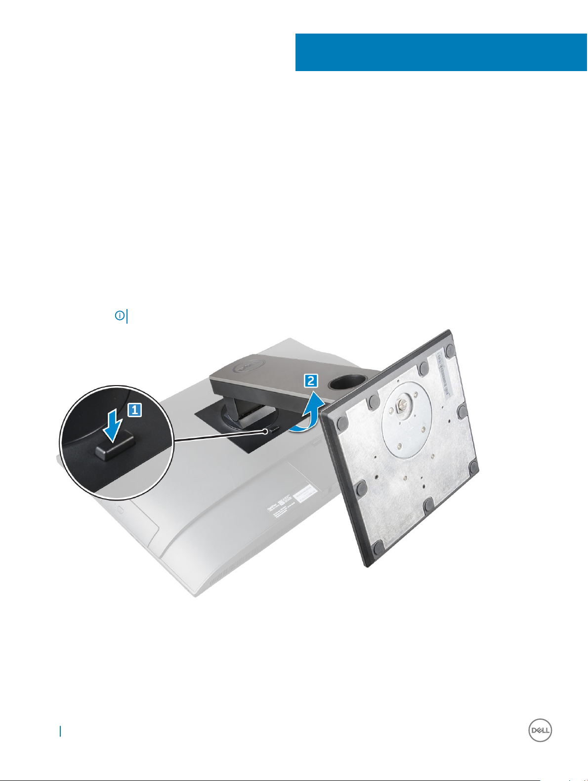
Removing the stand
1 Follow the procedure in Before working inside your computer.
2 Place the computer on a at surface with the display facing downward.
3 To remove the stand:
a Press the tab on the cover to release the stand [1].
b Lift the stand upward [2].
NOTE: There are optional stands available but they will attach in a similar manner.
2
Installing the stand
1 Align the stand and slide it on the back of the computer.
2 Press the stand down till it snaps in.
3 Follow the procedure in After working inside your computer.
10 Извлечение и установка компонентов
Page 11
Cable cover
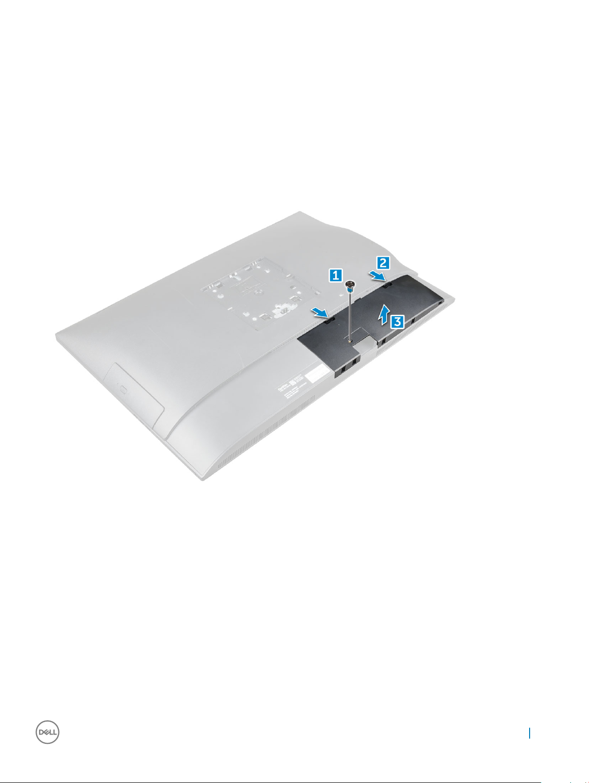
Removing the cable cover
1 Follow the procedure in Before working inside your computer.
2 Remove the stand.
3 To remove the cable cover:
a Remove the screw that secures the cable cover to the computer [1].
b Push the release tabs to release the cable cover [2].
c Lift the cable cover away from the computer [3].
Installing the cable cover
1 Align the notches on the cable cover to the holes on the computer and press the cable cover until it snaps in.
2 Tighten the screw to secure the cable cover to the computer.
3 Install the stand.
4 Follow the procedure in After working inside your computer.
Задняя крышка
Removing the back cover
1 Follow the procedure in Before working inside your computer.
2 Remove the:
Извлечение и установка компонентов 11
Page 12
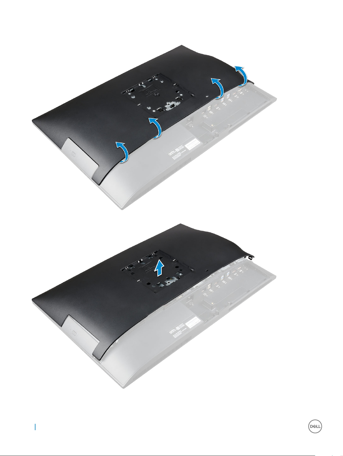
a stand
b cable cover
3 Pry the edges of the back cover from the bottom to release it from the computer.
4 Lift the back cover from the computer.
12 Извлечение и установка компонентов
Page 13
Installing the back cover
1 Align the notches on the back cover to the holes on the computer, and press the back cover until it snaps in.
2 Install the:
a cable cover
b stand
3 Follow the procedure in After working inside your computer.
Оптический дисковод
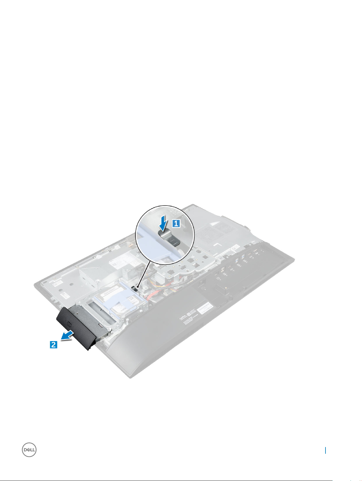
Removing the optical drive assembly
1 Follow the procedure in Before working inside your computer.
2 Remove the:
a stand
b back cover
3 To remove the optical drive assembly:
a Press the securing tab at the base of the drive to release the optical drive assembly [1].
b Slide the optical drive assembly to remove it away from the computer [3][2].
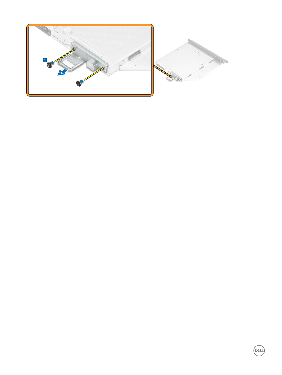
4 To remove the optical drive bracket:
a Remove the screws that secure the optical drive bracket [1].
b Remove the bracket away from the optical drive [2].
Извлечение и установка компонентов 13
Page 14
Installing the optical drive assembly
1 Place the bracket to align the screw holders on the optical drive.
2 Tighten the screws to secure the bracket to the optical drive.
3 Insert the optical drive assembly into the drive slot, until it snaps in.
4 Install the:
a back cover
b stand
5 Follow the procedure in After working inside your computer.
Power and On-Screen Display (OSD) buttons board
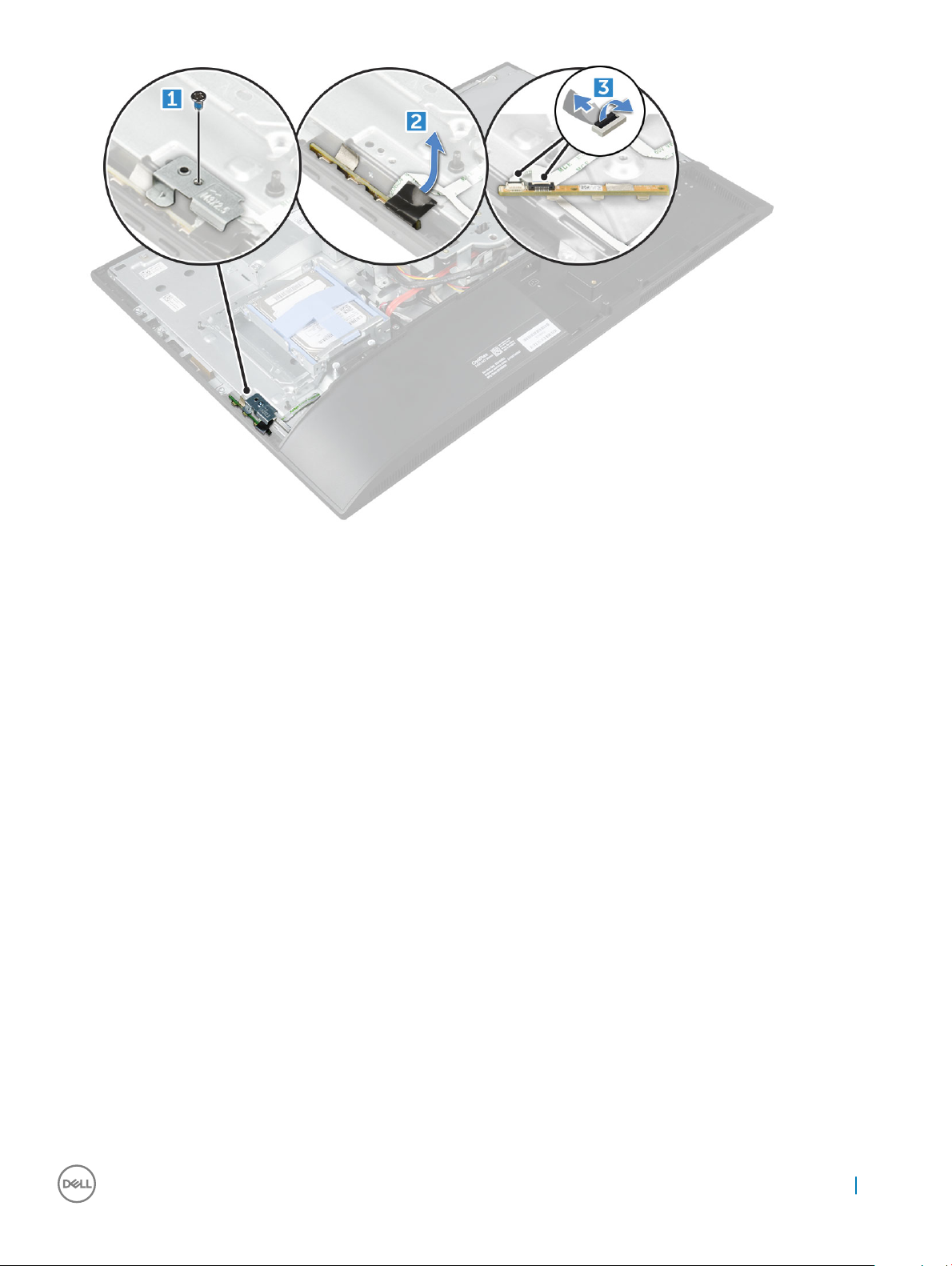
Removing the power and On-Screen Display (OSD) buttons
board
1 Follow the procedure in Before working inside your computer.
2 Remove the:
a stand
b back cover
3 To remove the power and OSD buttons board:
a Remove the screw to remove the metal plate that secures the power and OSD buttons board to the computer [1].
b Peel o the tape from the OSD buttons board [2].
c Remove the power and OSD buttons board from the chassis.
d Disconnect the cables from the power and OSD buttons board to release the board from the computer [3].
14 Извлечение и установка компонентов
Page 15
Installing the power and OSD buttons board
1 Connect the cable to the power and OSD buttons board.
2 Ax the tape on the OSD buttons board.
3 Insert the power and OSD buttons board into the slot.
4 Align the metal plate on the power and OSD buttons board.
5 Tighten the screw to secure the power and OSD buttons board.
6 Install the:
a back cover
b stand
7 Follow the procedure in After working inside your computer.
Speaker cover
Removing the speaker cover
1 Follow the procedure in Before working inside your computer.
2 Remove the:
a stand
b cable cover
c back cover
3 To remove the speaker cover:
a Remove the screws that secure the speaker cover to the computer [1].
b Slide the speaker cover to release it from the computer [2].
Извлечение и установка компонентов 15
Page 16
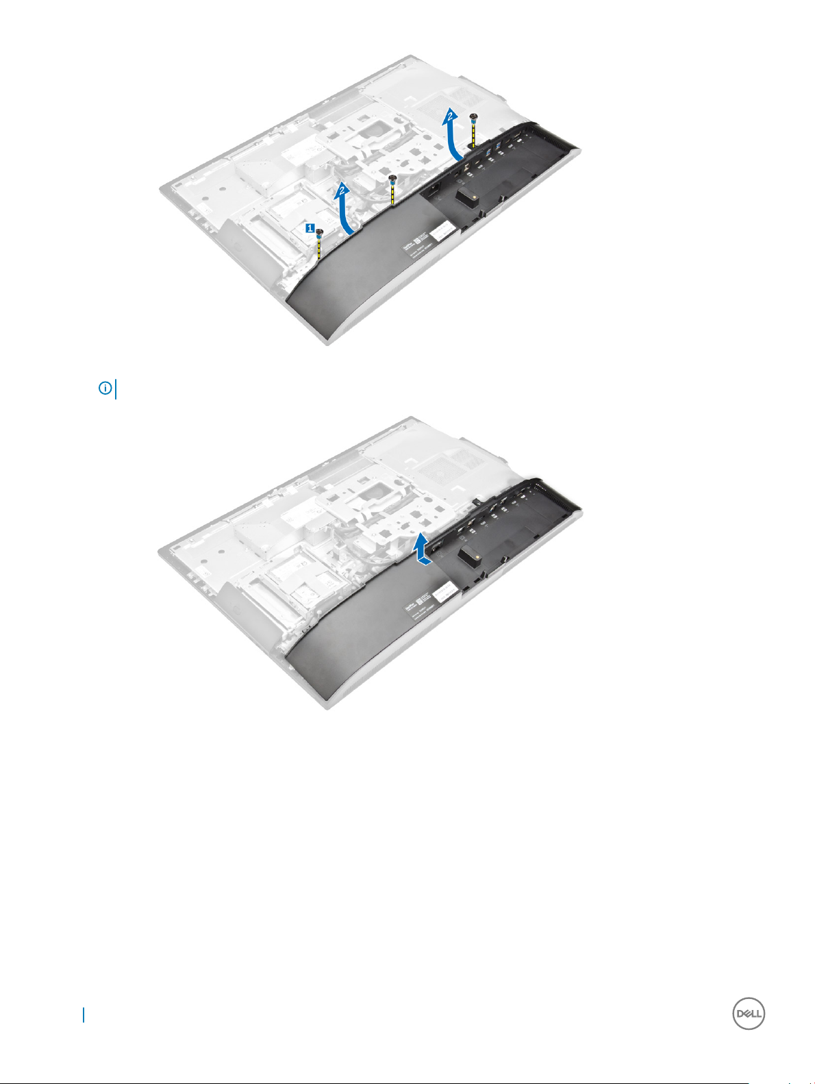
4 Pull and remove the speaker cover from the computer.
NOTE: To avoid damage to the back cover, release it from the pull tabs.
Installing the speaker cover
1 Align and push the speaker cover to pop tabs into its position on the back of the computer.
2 Tighten the screws to secure the speaker cover to the computer.
3 Install the:
a back cover
b cable cover
c stand
4 Follow the procedure in After Working Inside Your Computer.
16 Извлечение и установка компонентов
Page 17
Жесткий диск
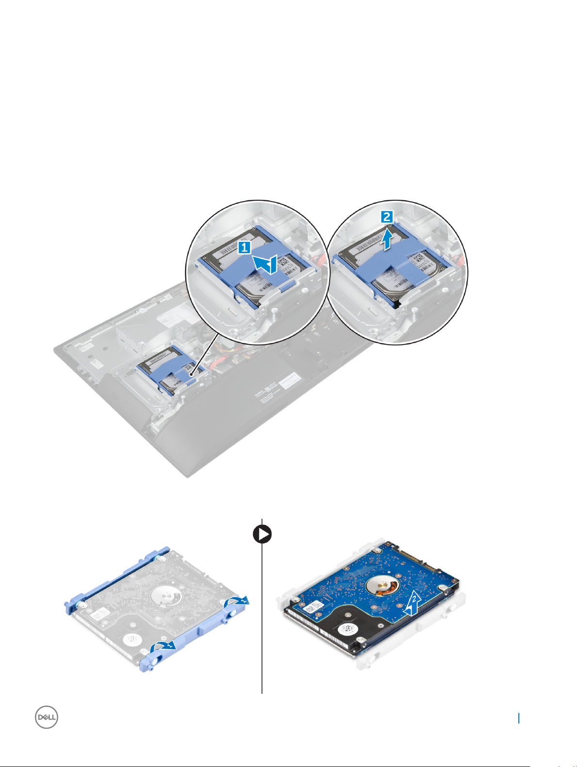
Removing the hard drive assembly
1 Follow the procedure in Before working inside your computer.
2 Remove the:
a stand
b back cover
3 To remove the hard drive assembly:
a Press the tab on the bracket, and slide the hard-drive assembly until the tabs are released from either side of the assembly [1].
b Slide the hard-drive assembly upwards to remove it from the computer [2].
4 To remove the hard drive bracket:
a Pry the edges of the bracket to release the hard drive [1].
b Slide the hard drive and lift it away from the bracket [2].
Извлечение и установка компонентов 17
Page 18
Installing the hard drive assembly
1 Align the hard drive until the notches are aligned and the hard drive is secured in the bracket.
2 Place the hard drive onto the hard drive cage until the notches are aligned, then slide the Hard Drive assembly until the tab locks into
the cage.
3 Install the:
a back cover
b stand
4 Follow the procedure in After working inside your computer.
System board shield
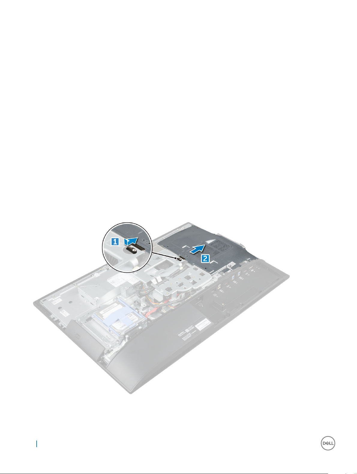
Removing the system board shield
1 Follow the procedure in Before working inside your computer.
2 Remove the:
a stand
b back cover
3 To remove the system board shield:
a Press the securing tab to release the system board shield from the slots on the computer [1].
b Slide the system board shield away from the computer [2].
18 Извлечение и установка компонентов
Page 19
Installing the system board shield
1 Align and slide the system board shield until it snaps in.
2 Install the:
a back cover
b stand
3 Follow the procedure in After working inside your computer.
Модуль памяти
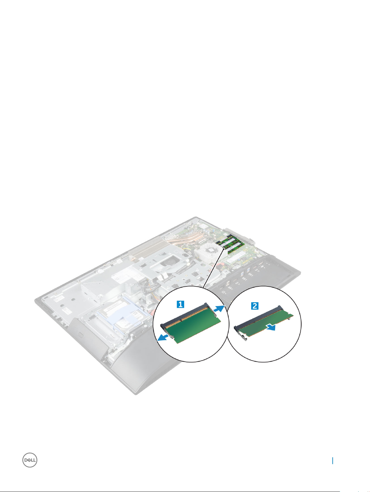
Removing the memory module
1 Follow the procedure in Before working inside your computer.
2 Remove the:
a stand
b back cover
c system board shield
3 To remove the memory module:
a Pry the retention clips away from the memory module until it pops up [1].
b Lift the memory module from the connector [2].
Installing the memory module
1 Insert the memory module on the memory connector until the clips secure the memory module.
2 Install the:
Извлечение и установка компонентов 19
Page 20
a system board shield
b back cover
c stand
3 Follow the procedure in After working inside your computer.
Твердотельный накопитель (SSD)
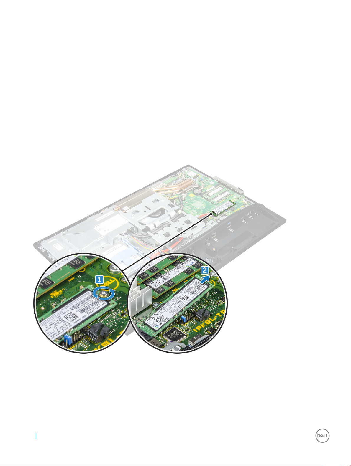
Removing the SSD card
1 Follow the procedure in Before working inside your computer.
2 Remove the:
a stand
b back cover
c system board shield
3 To remove the SSD card:
a Remove the screw that secures the SSD card to the computer [1].
b Lift the SSD card away from the connector [2].
Installing the SSD card
1 Insert the SSD card into the connector.
2 Tighten the screw to secure the SSD card to the system board.
3 Install the:
a system board shield
20 Извлечение и установка компонентов
Page 21
b back cover
c stand
4 Follow the procedure in After working inside your computer.
Батарейка типа "таблетка"
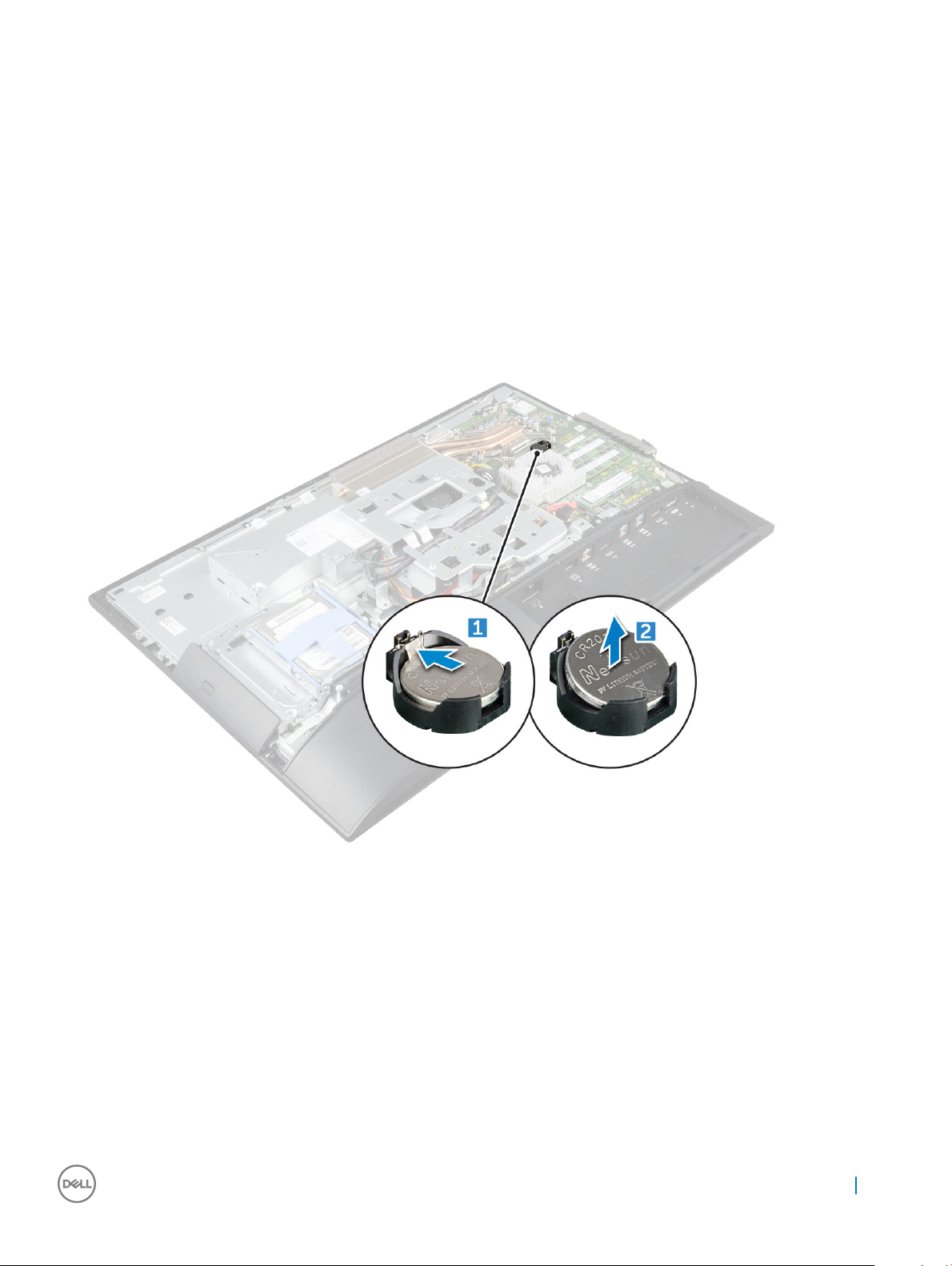
Removing the coin cell battery
1 Follow the procedure in Before working inside your computer.
2 Remove the:
a stand
b back cover
c system board shield
3 Press the latch to release the coin cell battery and remove it from the computer.
Installing the coin cell battery
1 Insert the coin cell battery into the slot on the system board until it ts securely.
2 Install the:
a system board shield
b back cover
c stand
3 Follow the procedure in After working inside your computer.
Извлечение и установка компонентов 21
Page 22
Плата WLAN
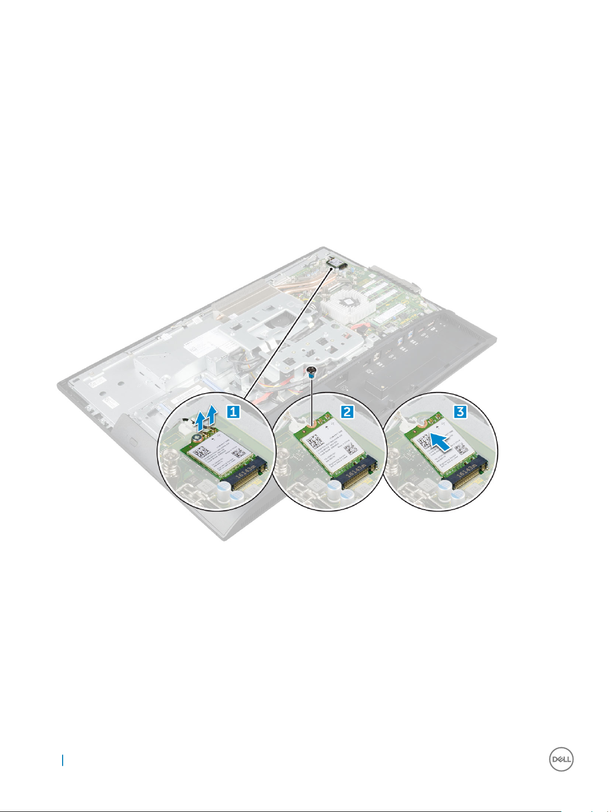
Removing the WLAN card
1 Follow the procedure in Before working inside your computer.
2 Remove the:
a stand
b back cover
c system board shield
3 To remove the WLAN card:
a Disconnect the antenna cables from the connectors on the WLAN card [1].
b Remove the screw that secures the WLAN card to the system board [2].
c Hold the WLAN card and pull it from the connector on the system board [3].
Installing the WLAN card
1 Align the WLAN card to the connector on the system board.
2 Tighten the screw to secure the WLAN card to the system board.
3 Connect the antenna cables to the connectors on the WLAN card.
4 Install the:
a system board shield
b back cover
c stand
5 Follow the procedure in After working inside your computer.
22 Извлечение и установка компонентов
Page 23
Радиатор
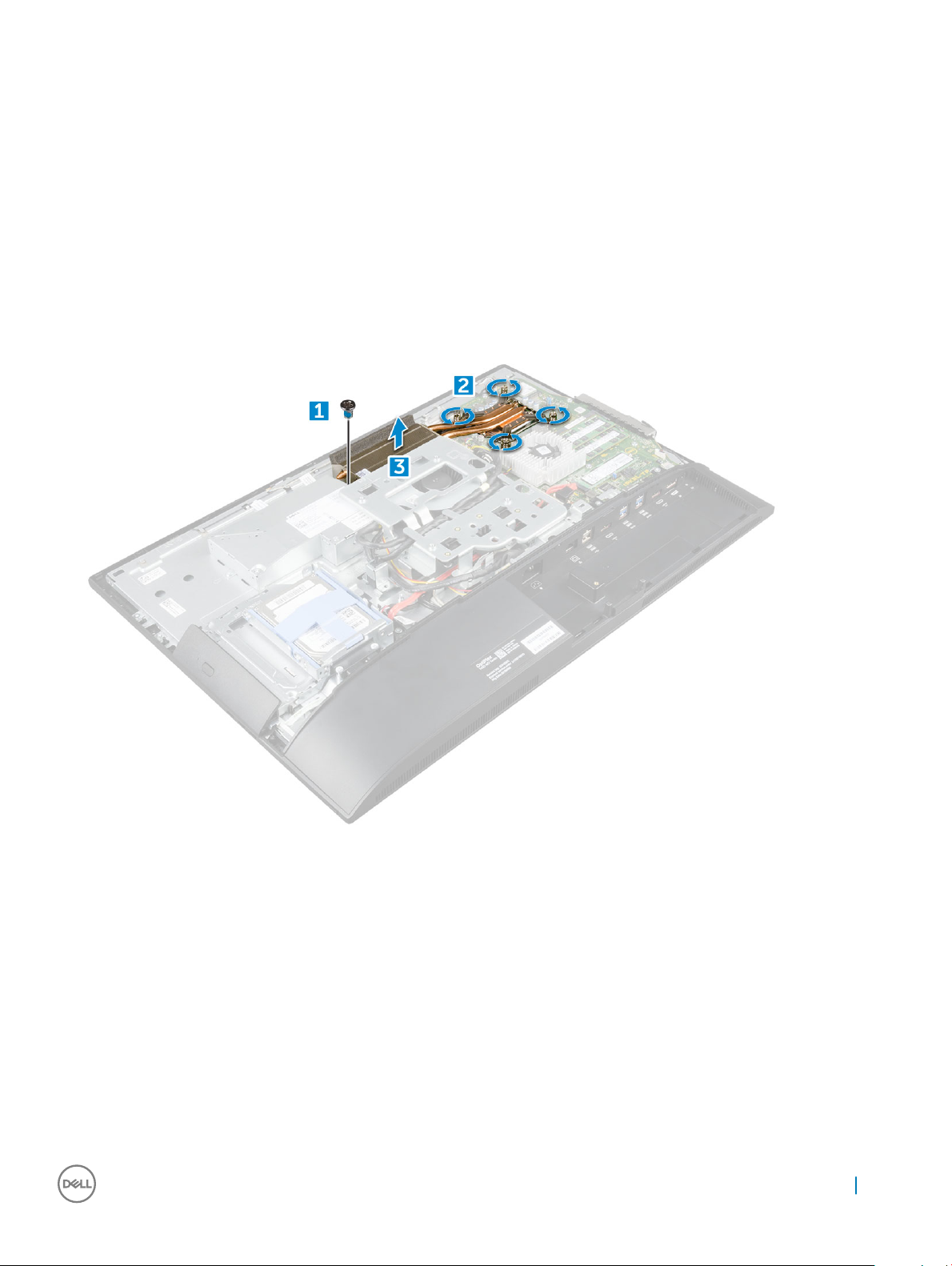
Removing the heat sink
1 Follow the procedure in Before working inside your computer.
2 Remove the:
a stand
b back cover
c system board shield
3 To remove the heat sink:
a Remove the screws that secure the heat sink to the chassis [1, 2].
b Lift the heat sink away from the computer [3].
Installing the heat sink
1 Align and place the heat sink in the slot.
2 Tighten the screws to secure the heat sink to the computer.
3 Install the:
a system board shield
b back cover
c stand
4 Follow the procedure in After working inside your computer.
Извлечение и установка компонентов 23
Page 24
Динамик
Removing the speaker module
1 Follow the procedure in Before working inside your computer.
2 Remove the:
a stand
b back cover
c cable cover
d speaker cover
e system board shield
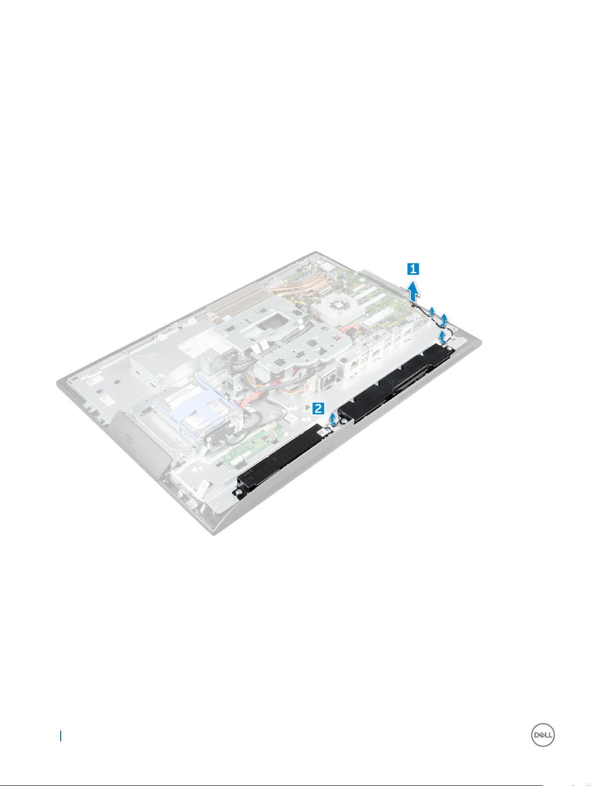
3 To release the speaker module:
a Disconnect the speaker cable from the connector on the system board [1].
b Unthread the speaker cables from the retention clips [2].
4 To remove the speaker module:
a Remove the screws that secure the speaker module to the chassis [1].
b Lift the speaker module and remove it from the chassis [2].
24 Извлечение и установка компонентов
Page 25

Installing the speaker module
1 Insert the speaker module into the slot on the chassis.
2 Tighten the screws to secure the speaker to the chassis.
3 Secure the speaker cables through the retention clips.
4 Connect the speaker cable to the connector on the system board.
5 Install the:
a system board shield
b speaker cover
c back cover
d cable cover
e stand
6 Follow the procedure in After working inside your computer.
Блок питания
Removing the Power Supply Unit (PSU)
1 Follow the procedure in Before working inside your computer.
2 Remove the:
a stand
b back cover
c cable cover
d speaker cover
e system board shield
3 To release the PSU cable:
Извлечение и установка компонентов 25
Page 26

a Unthread the power supply cables from the retention clips in the chassis [1].
b Disconnect the power supply cable from the connector on the system board [2].
NOTE: Press lock clip to release the power supply cable from the system board.
4 To release the PSU:
•
a Remove the screw that secures the power supply socket to the chassis [1].
b Slide the socket to remove it from the computer [2].
NOTE: There is an additional cable retention clip on the side of the VESA mount bracket. The PSU near that is
not visible in the removing cables from retention clips image.
26 Извлечение и установка компонентов
Page 27

5 To remove the PSU:
a Remove the screw that secure the PSU to the chassis [1].
b Slide the PSU and lift it away from the chassis [2].
Извлечение и установка компонентов 27
Page 28

Installing the Power Supply Unit (PSU)
1 Place the PSU on the chassis.
2 Tighten the screw to secure the PSU to the chassis.
3 Place the power supply socket in the slot on the chassis.
4 Tighten the screw to secure the power supply socket to the chassis.
5 Secure the power supply cable on the retention clips in the chassis.
6 Connect the power supply cables to the connectors on the system board.
7 Install the:
a system board shield
b speaker cover
c cable cover
d back cover
e stand
8 Follow the procedure in After working inside your computer.
VESA mount bracket
Removing the VESA mount bracket
1 Follow the procedure in Before working inside your computer.
2 Remove the:
a stand
b back cover
c cable cover
d speaker cover
e system board shield
f power supply unit
3 To remove the VESA mount bracket:
a Remove the screws that secure the VESA mount bracket to the computer [1].
b Lift the bracket away from the computer [2].
28 Извлечение и установка компонентов
Page 29

Installing the VESA mount bracket
1 Align and place the bracket in the slot on the computer.
2 Tighten the screws that secure the VESA mount bracket to the computer.
3 Install the:
a power supply unit
b system board shield
c speaker cover
d cable cover
e back cover
f stand
4 Follow the procedure in After working inside your computer.
Converter board
Removing the converter board
1 Follow the procedure in Before working inside your computer.
2 Remove the:
a stand
b back cover
c cable cover
d speaker cover
e system board shield
f power supply unit
Извлечение и установка компонентов 29
Page 30

g VESA mount bracket
3 To remove the converter board:
a Disconnect the convertor board cable from the converter board [1].
b Disconnect the display backlight cable from the converter board [2].
c Remove the screws that secure the converter board to the computer [3].
d Lift the converter board away from the computer [4].
Installing the converter board
1 Place the convertor board in the slot.
2 Tighten the screws to secure the converter board to the chassis.
3 Connect the converter board cable and display backlight cable to the connectors on the converter board.
4 Install the:
a VESA mount bracket
b power supply unit
c system board shield
d speaker cover
e cable cover
f back cover
g stand
5 Follow the procedure in After working inside your computer.
30 Извлечение и установка компонентов
Page 31

Системный вентилятор
Removing the system fan
1 Follow the procedure in Before working inside your computer.
2 Remove the:
a stand
b back cover
c cable cover
d speaker cover
e system board shield
f power supply unit
g VESA mount bracket
3 To remove the system fan:
a Disconnect the system fan cable from the connector on the system board [1].
b Remove the screws that secure the system fan to the computer [2].
c Lift the system fan away from the computer [3].
Installing the system fan
1 Align and place the system fan in the slot on the chassis.
2 Tighten the screws to secure the system fan to the system board.
3 Connect the system fan cable to the connector on the system board.
4 Install the:
a VESA mount bracket
b power supply unit
Извлечение и установка компонентов 31
Page 32

c system board shield
d speaker cover
e cable cover
f back cover
g stand
5 Follow the procedure in After working inside your computer.
Intrusion switch
Removing the intrusion switch
1 Follow the procedure in Before working inside your computer.
2 Remove the:
a stand
b back cover
c cable cover
d speaker cover
e system board shield
f power supply unit
g VESA mount bracket
3 To remove the intrusion switch:
a Disconnect the intrusion switch cable from the connector on the system board [1].
b Unthread the intrusion switch cable from the retention clips on the computer [2].
c Remove the screw that secures the intrusion switch to the computer [3].
d Slide and lift the intrusion switch away from the computer [4].
4 Perform the following instructions as shown in the illustration:
a Remove the screw that secures the intrusion switch to the chassis [1].
b Slide and lift the intrusion switch to remove it from the computer [2].
32 Извлечение и установка компонентов
Page 33

Installing the intrusion switch
1 Place the intrusion switch in the slot on the computer.
2 Tighten the screw to secure the intrusion switch to the chassis.
3 Route intrusion switch cable along the retention clips on the chassis.
4 Connect the intrusion switch cable to the connector on the system board.
5 Install:
a VESA mount bracket
b power supply unit
c system board shield
d speaker cover
e cable cover
f back cover
g stand
6 Follow the procedures in After working inside your computer.
Процессор
Removing the processor
1 Follow the procedure in Before working inside your computer.
2 Remove the:
a stand
b back cover
c cable cover
d speaker cover
e speaker
f VESA mount bracket
g system board shield
h SSD card
i WLAN card
j memory
k heat sink
l system fan
3 To remove the processor:
Извлечение и установка компонентов 33
Page 34

a Release the socket lever by pushing the lever down and out from under the tab on the processor shield [1].
b Lift the lever upward and lift the processor shield [2].
CAUTION: The processor socket pins are fragile and can be permanently damaged. Be careful not to bend
the pins in the processor socket when removing the processor out of the socket.
c Lift the processor out of the socket [3].
NOTE: After removing the processor, place it in an antistatic container for reuse, return, or temporary
storage. Do not touch the bottom of the processor to avoid damage to the processor contacts. Touch only
the side edges of the processor.
Installing the processor
1 Align the processor with the socket keys.
CAUTION: Do not use force to seat the processor. When the processor is positioned correctly, it engages easily into the
socket.
2 Align the pin-1 indicator of the processor with the triangle on the socket.
3 Place the processor on the socket such that the slots on the processor align with the socket keys.
4 Close the processor shield by sliding it under the retention screw.
5 Lower the socket lever and push it under the tab to lock it.
6 Install:
a system fan
b heat sink
c memory
d WLAN card
e SSD card
f system board shield
g VESA mount bracket
h cable cover
i speaker
j speaker cover
k back cover
l stand
7 Follow the procedure in After working inside your computer.
Системная плата
Removing the system board
1 Follow the procedure in Before working inside your computer.
2 Remove the:
34 Извлечение и установка компонентов
Page 35

a stand
b back cover
c cable cover
d speaker cover
e speaker
f hard drive
g optical drive
h VESA mount bracket
i system board shield
j SSD card
k WLAN card
l memory
m heat sink
n system fan
o processor
p coin cell battery
q power supply unit
3 Disconnect the following cables from the system board:
a intrusion switch [1]
b hard drive and optical drive [2]
c SATA [3]
d speaker [4]
e camera and microphone [5]
f display [6]
g system fan [7]
4 To remove the system board:
a Remove the screws that secure the system board to the chassis [1].
b Slide and lift the system board away from the computer [2].
Извлечение и установка компонентов 35
Page 36

Installing the system board
1 Place the system board on the computer.
2 Connect all the cables to the system board.
3 Tighten the screws to secure the system board to the base panel.
4 Install the:
a power supply unit
b coin cell battery
c system fan
d processor
e heat sink
f memory
g WLAN card
h SSD card
i system board shield
j VESA mount bracket
k optical drive
l hard drive
m cable cover
n speaker
o speaker cover
p back cover
q stand
5 Follow the procedure in After working inside your computer.
36 Извлечение и установка компонентов
Page 37

System board layout
1 LVDS connector 2 Camera connector
3 Antenna wire clip 4 WLAN connector
5 Jumper connector 6 Coin cell battery
7 Speaker connector 8 Memory module connector
9 Jumper connector 10 M.2 SSD slot
11 Optical drive connector 12 Intrusion switch connector
13 Hard drive connector 14 Side buttons connector
15 Touchpad connector 16 CAC/PIV connector (reserved)
17 Converter board connector 18 Windows serial debug connector
19 HDD/ODD power connector 20 LPC debug connector
21 APS debug connector 22 Power supply connector
23 CPU fan connector 24 CPU fan connector
25 CPU socket
Chassis frame
Извлечение и установка компонентов 37
Page 38

Removing the chassis frame
NOTE: These instructions are applicable only for systems with a non-touch screen display.
1 Follow the procedure in Before working inside your computer.
2 Remove the:
a stand
b back cover
c cable cover
d speaker cover
e speaker
f hard drive
g optical drive
h VESA mount bracket
i system board shield
j SSD card
k WLAN card
l memory
m heat sink
n system fan
o processor
p coin cell battery
q power supply unit
r system board
3 Unroute the cables though the retention clips.
4 To remove the chassis frame:
38 Извлечение и установка компонентов
Page 39

•
a Peel the adhesive tapes that secure the chassis frame [1].
b Remove the screws that secure the chassis frame to the computer. [2].
c Remove the cables from the chassis frame and lift the chassis frame away from the computer. [3].
NOTE: There is a cable that is taped/glued down to the chassis frame. That cable runs down from the On-
Screen Display (OSD) and into a connector on the Display Bezel for the Power Button board below the OSD
Button board. Trying to lift the chassis frame without disconnecting this cable rst could damage the connector.
NOTE: Chassis frame screws have M3 stamped next to them.
Installing the chassis frame
1 Place the chassis frame on the computer.
2 Tighten the screws to secure the chassis frame to the computer.
3 Ax the adhesive tapes to secure the chassis frame to the computer.
4 Install the:
a system board
b power supply unit
c coin cell battery
d system fan
e processor
f heat sink
g memory
h WLAN card
i system board shield
j SSD card
k VESA mount bracket
l optical drive
m hard drive
n cable cover
o speaker
p speaker cover
q back cover
r stand
5 Follow the procedure in After working inside your computer.
Извлечение и установка компонентов 39
Page 40

Панель дисплея
Removing the display panel
1 Follow the procedure in Before working inside your computer.
2 Remove the:
a stand
b back cover
c cable cover
d speaker cover
e speaker
f hard drive
g optical drive
h VESA mount bracket
i system board shield
j SSD card
k WLAN card
l memory
m heat sink
n system fan
o processor
p coin cell battery
q power supply unit
r system board
s chassis frame
3 To remove the display panel:
a Disconnect the cables from the connectors [1].
b Remove the screws that secure the display panel to the bezel.[2].
c Lift the display panel away from the bezel. [3].
Installing the display panel
1 Align the display panel with the screw holes on the computer.
2 Tighten the screws to secure the display panel to the computer.
3 Connect the cables to the connectors.
40 Извлечение и установка компонентов
Page 41

4 Install the:
a chassis frame
b system board
c power supply unit
d coin cell battery
e system fan
f processor
g heat sink
h memory
i WLAN card
j system board shield
k SSD card
l VESA mount bracket
m optical drive
n hard drive
o cable cover
p speaker
q speaker cover
r back cover
s stand
5 Follow the procedure in After working inside your computer.
Извлечение и установка компонентов 41
Page 42

3
M.2 Intel Optane Memory Module 16 GB
Overview
This document describes the specications and capabilities of the Intel® OptaneTM memory module. The Intel® OptaneTM memory is a
system acceleration solution developed for 7th Generation Intel® CoreTM processor-based platforms. The Intel® OptaneTM memory
module is architected with the high performance controller interface Non-Volatile Memory Express (NVMe*)- delivering outstanding
performance, low latency and quality of service. NVMe uses a standardized interface that enables higher performance and lower latency
than pervious interfaces. Intel® OptaneTM memory module oers capacities of 16 GB and 32 GB in small M.2 form factors.
The Intel® OptaneTMmemory module oers a system acceleration solution using the latest Intel® Rapid Storage Technology (Intel® RST)
15.5X.
The Intel® OptaneTM memory module includes these key features:
• PCIe 3.0x2 with NVMe interface
• Uses Intel’s revolutionary new storage technology, 3D XpointTM memory media
• Ultra-low latency; exceptional responsiveness
• Performance saturation at queue depth of 4 and lower
• Very high endurance capabilities
Intel®Optane
The following table describes the driver requirements for the Intel® OptaneTM memory system acceleration us a component of Intel®
Rapid Storgae Technology 15.5 or later and requires 7th generation Intel® Core TM processor-based platforms to function.
Table 1. Driver Support
Support Level Operating System Description
Intel® OptaneTM Memory with System Acceleration Conguration
Using Rapid Storage Technology Driver
NOTES:
1 Intel® RST driver requires device to be attached to RST enabled PCIe lanes on 7th generation Intel® CoreTM.
TM
Memory Module Driver Requirements
Windows 10*64 bit
1
Installing M.2 Intel Optane Memory Module 16 GB
1 Follow the procedure in Before working inside your computer.
2 Remove the:
a stand
b back cover
c system board shield
3 To remove M.2 Intel optane memory module::
a Remove white adhesive tape from the box.
42 M.2 Intel Optane Memory Module 16 GB
Page 43

b Place the M.2 Intel optane memory module into the slot on the computer.
c Tighten the screw that secures the M.2 Intel optane memory module on the computer.
Product specications
Features
Capacities 16 GB, 32 GB
Expansion cards PCIe 3.0 x 2
M.2 form factors (all densities) 2280–S3–B-M
Specication
M.2 Intel Optane Memory Module 16 GB 43
Page 44

Performace
• Seq R/W: Up to 1350/290 MS/s
• QD4 4HB Random Read: 240K + IOPs
• QD4 4HB Random Write: 240K + IOPs
Latency (average sequential)
• Read 8.25 µ
• Write: 30 µ
Components
• Intel 3D XPoint Memory Media
• Intel Controller and Firmware
• PCIe 3.0x2 with NVMe Interface
• Intel Rapid Storage Technology 15.2 or later
Operating System Support Windows 10 64 bit
Supported Platforms 7th generation or newer Intel Core processor based platforms
Power
• 3.3V Supply Rail
• Active: 3.5 W
• Drive Idel :900mW to 1.2W
Compliance
• NVMe Express 1.1
• PCI Express Base speciation rev 3.0
• PCI M.2 HS Spec
Certication and Declarationsµ UL, CE, C-Tick, BSMI, KCC, Microsoft WHQL, Microsoft WHCK,
VCCI
Endurance Rating
• 100 GB Writes per day
• Upto 182.3 TBW (Terabytes written)
Temperature Specication
• Operating: 0 to 70º C
• Non-Opearting: 10 to 85º C
• Temperature monitoring
Shock 1500 G/0.5msec
Vibration
• Operating: 2.17 G
• Non-Operating: 3.13 G
Altitude (Simulated)
• Operating: –1,000 ft to 10,000 ft
• Non-Operating: –1,000 ft to 40,000 ft
Product Ecological Compliance RoHS
Reliability
• Uncorrectable Bit Error Rate (UBER): 1 sector per 1015 bits read
• Mean Time Between Failure (MTBF): 1.6 million hours
(5–800Hz)
RMs
RMS
(5–800Hz)
44 M.2 Intel Optane Memory Module 16 GB
Page 45

Environmental Conditions
Table 2. Temperature, Shock, Vibration
Temperature M.2 2280 form factor
Operating
Non-operating
1
2
0–70º C
-10–85º C
Temperature Gradient
Operating
Non-operating
Humidity
Operating
Non-operating
Shock and Vibration Range
4
Shock
Operating
Non-operating
Vibration
Operating
Non-operating
NOTES:
1 Operating temperature is targeted for 70º C.
2 Please contact your Intel representative for details on the non-operating temperature range.
3 Temperature gradient measured without condensation.
4 Shock specication assume the device is mounted securely with the input vibration applied to the drive-mounting screws. Stimulus
5 Vibration specications assume the device is mounted securely with the input vibration applied to the drive-mounting screws.
5
may be applied in the X,Y, or Z axis shock specication is measured using Root Mean Squared (RMS) value.
Stimulus may be applied in the X, Y, or Z axis. Vibration specicities is measured using RMS value.
3
30º C/hr (Typical)
30º C/hr (Typical)
5–95%
5–95%
1500 G / 0.5 ms
230 G / 3 msec
2.17 G
3.13 G
(5–800Hz) Max
RMS
(5–800Hz) Max
RMS
Troubleshooting
1 The Intel Optane Memory model name "NVME INTEL MEMPEK1W01" in Device Manager does not match in the Intel Rapid Storage
Technology user interface; it only shows a part of the serial number information. This is a known issue and does not impede the
functionality of the Intel Optane Memory.
Device Manager: NVME INTEL MEMPEK1W01
IRST UI: INTEL MEMPEK1W016GA
M.2 Intel Optane Memory Module 16 GB
45
Page 46

2 During the rst-time boot up, the system will scan the pairing status as below screen shot after shutdown. It’s working as designed
and the message will not appear again in following boot ups.
46 M.2 Intel Optane Memory Module 16 GB
Page 47

Технология и компоненты
В данной главе представлены подробные сведения о технологии и компонентах, доступных в системе.
Темы:
• Наборы микросхем
• Storage options
• Memory congurations
• DDR4
Наборы микросхем
Все ноутбуки обмениваются данными с процессором через набор микросхем. Этот ноутбук поставляется с набором
микросхем Intel Mobile СМ238.
Идентификация набора микросхем в диспетчере
4
устройств Windows 10
1 Нажмите мышью Поле поиска Cortana и введите Панель управленияl. Найдя нужный элемент, нажмите его мышью
или выберите его на клавиатуре и нажмите ВВОД.
2 На панели управления выберите Диспетчер устройств.
3 Разверните пункт Системные устройства и найдите набор микросхем.
Storage options
This topic details the supported storage options.
Hard drives
Table 3. Hard drive
• 2.5" 500 GB SATA 5400 RPM Hard Disk Drive
• 2.5" 500 GB SATA 7200 RPM Hard Disk Drive
• 2.5" 500 GB SATA 5400 RPM Solid State Hybrid Drive with 8
GB Flash
• 2.5" 500 GB SATA 7200 RPM Self Encrypting Drive (OPAL
FIPS)
• 2.5" 1.0 TB SATA 7200 RPM Hard Disk Drive
• 2.5" 1.0 TB SATA 5400 RPM Solid State Hybrid Drive w/ 8GB
Flash
• 2.5" 2.0 TB SATA 5400 RPM Hard Disk Drive
Технология и компоненты 47
Page 48

Solid State Drives (SSD)
Table 4. SSD
• 2.5" 256 GB SATA Solid State Drive Class 20
• 2.5" 512 GB SATA Solid State Drive Class 20
• M.2 128 GB SATA Solid State Drive Class 20
• M.2 256 GB PCIe NVMe Solid State Drive Class 40
• M.2 256 GB PCIe NVMe Self Encrypting Solid State Drive Class
40
• M.2 512 GB PCIe NVMe Solid State DriveClass 40
• M.2 1 TB PCIe NVMe Solid State Drive Class 40
Определение жесткого диска в Windows 10
Щелкните Все параметры на панели чудо-кнопок ОС Windows 10.
1
2 Щелкните Панель управления, выберите Диспетчер устройств и разверните Дисковые устройства.
Жесткий диск указан в разделе Дисковые устройства.
Вход в режим настройки BIOS
1 Включите или перезагрузите ноутбук.
2 Когда на экране появится логотип Dell, выполните одно из следующих действий, чтобы войти в программу настройки
BIOS:
• С помощью клавиатуры сделайте следующее. Нажимайте клавишу F2 до тех пор, пока не появится сообщение
Entering BIOS (идет вход в режим настройки BIOS). Для входа в меню выбора загрузки нажмите клавишу F12.
Жесткий диск указан в разделе Информация о системе, в группе Общая.
Memory congurations
The supported memory congurations for are as follows:
• 2GB DDR4, 2400MHz, (1 x 2GB)- Linux operating system only
• 4GB DDR4, 2400MHz, (1 x 4GB)
• 8GB DDR4, 2400MHz, (1 x 8GB)
• 8GB DDR4, 2400MHz, (2 x 4GB)
• 16GB DDR4, 2400MHz, (2 x 8GB)
• 32GB DDR4, 2400MHz, (2 x 16GB)
: If this computer is purchased with Intel 6th Generation CPUs, the maximum MHz the computer can achieve is 2133.
NOTE
48 Технология и компоненты
Page 49

Проверка системной памяти в Windows 10 и Windows 7
Windows 10
1 Нажмите кнопку Windows и выберите All Settings (Все настройки) > System (Система).
2 В разделе System (Система) щелкните About (О программе).
Windows 7
• Нажмите Пуск → Панель управления → Система.
DDR4
DDR4 (double data rate fourth generation) memory is a higher-speed successor to the DDR2 and DDR3 technologies and allows up to 512
GB in capacity, compared to the DDR3's maximum capacity of 128 GB per DIMM. DDR4 synchronous dynamic random-access memory is
keyed dierently from both SDRAM and DDR to prevent the user from installing the wrong type of memory into the system.
DDR4 needs 20 percent less or just 1.2 volts, compared to DDR3 which requires 1.5 volts of electrical power to operate. DDR4 also supports
a new, deep power-down mode that allows the host device to go into standby without needing to refresh its memory. Deep power-down
mode is expected to reduce standby power consumption by 40 to 50 percent.
Key Specications
The following table lists the specications' comparison between DDR3 and DDR4:
Table 5. DDR3 vs DDR4
Feature/Option DDR3 DDR4 DDR 4 Advantages
Chip Densities 512 Mb-8 Gb 4 Gb-16 Gb Larger DIMM capacities
Data rates 800 Mb/s-2133 Mb/s 1600 Mb/s-3200 Mb/s Migration to higher speed I/O
Voltage 1.5 V 1.2 V Reduced memory power
demand
Low voltage standard Yes (DDR3L at 1.35V) Anticipated at 1.05V Memory Power Reductions
Internal banks 8 16 Higher data rates
Bank groups (BG) 0 4 Faster burst accesses
VREF inputs 2 —DQs and CMD/ADDR 1 — CMD/ADDR VREFDQ Now Internal
tCK — DLL Enabled 300 Mhz-800 Mhz 667Mhz-1.6Ghz Higher data rates
tCK — DLL Disabled 10MHz – 125MHz (optional) Undened to 125MHz DLL-o now fully supported
Read Latency AL+CL AL+CL Expanded values
Write Latency AL+CWL AL+CWL Expanded values
DQ Driver (ALT) 40&Omega 48&Omega Optimal for PtP Applications
Технология и компоненты 49
Page 50

Feature/Option DDR3 DDR4 DDR 4 Advantages
DQ Bus SSTL15 POD12 Less I/O Noise and Power
RTT Values (in &Omega) 120,60,40,30,20 240,120,80,60,48,40,34 Support for higher data rates
RTT not allowed READ Bursts Disables during READ Bursts Ease of use
ODT Modes Nominal, Dynamic Nominal, Dynamic,Park Add’l Control Mode; OTF Value
Change
ODT Control ODT Signaling Required ODT Signaling Not Required Ease of ODT Control; Allows
Non-ODT Routing, PtP Apps
Multi-Purpose Register Four Registers – 1 Dened, 3
RFU
DIMM Types RDIMM, LRDIMM, UDIMM,
SODIMM
DIMM Pins 240 (R, LR, U); 204 (SODIMM) 288 (R, LR, U); 260 (SODIMM)
RAS ECC CRC, Parity, Addressability, GDM More RAS features; improved
Four Registers – 3 Dened, 1
RFU
RDIMM, LRDIMM, UDIMM,
SODIMM
Provides Additional Specialty
Readout
data integrity
DDR4 Details
There are subtle dierences between DDR3 and DDR4 memory modules, as listed below.
Key notch dierence
The key notch on a DDR4 module is in a dierent location from the key notch on a DDR3 module. Both notches are on the insertion edge,
but the notch location on the DDR4 is slightly dierent, to prevent the module from being installed into an incompatible board or platform.
Figure 1. Notch dierence
Increased thickness
DDR4 modules are slightly thicker than DDR3, to accommodate more signal layers.
Figure 2. Thickness dierence
Curved edge
50 Технология и компоненты
Page 51

DDR4 modules feature a curved edge to help with insertion and alleviate stress on the PCB during memory installation.
Figure 3. Curved edge
Технология и компоненты 51
Page 52

5
Настройка системы
Программа настройки системы позволяет управлять и задавать параметры BIOS. Из программы настройки системы можно
выполнять следующие действия:
• изменять настройки NVRAM после добавления или извлечения оборудования;
• отображать конфигурацию оборудования системы;
• включать или отключать встроенные устройства;
• задавать пороговые значения производительности и управления энергопотреблением;
• управлять безопасностью компьютера.
Темы:
• Функция Boot Sequence (Последовательность загрузки)
• Клавиши навигации
• Параметры настройки системы
• Параметры настройки системы
• Updating the BIOS
• Системный пароль и пароль программы настройки
Функция Boot Sequence (Последовательность
загрузки)
Функция Boot Sequence (Последовательность загрузки) позволяет пользователям обойти установленную
последовательность загрузки с устройств и выполнить загрузку сразу с выбранного устройства (например, c оптического
или жесткого диска). Во время самотестирования при включении питания (POST), пока высвечивается логотип Dell, вы
можете сделать следующее.
• Войти в программу настройки системы нажатием клавиши <F2>
• Вызвать меню однократной загрузки нажатием клавиши <F12>
Меню однократной загрузки отображает доступные для загрузки устройства, а также функцию диагностики. Доступные
функции в меню загрузки:
• Removable Drive (if available) (Съемный диск (если таковой доступен))
• STXXXX Drive (Диск STXXXX)
ПРИМЕЧАНИЕ: XXX обозначает номер диска SATA.
• Optical Drive (if available) (Оптический диск (если доступно))
• Диагностика
ПРИМЕЧАНИЕ: При выборе пункта Diagnostics (Диагностика) отобразится экран ePSA diagnostics
(Диагностика ePSA).
Из экрана последовательности загрузки также можно войти в программу настройки системы.
52 Настройка системы
Page 53

Клавиши навигации
ПРИМЕЧАНИЕ: Для большинства параметров программы настройки системы, все сделанные пользователем
изменения регистрируются, но не вступают в силу до перезагрузки системы.
Клавиши Навигация
Стрелка вверх Перемещает курсор на предыдущее поле.
Стрелка вниз Перемещает курсор на следующее поле.
Клавиша Enter Позволяет выбрать значение в выбранном поле (если применимо) или пройти по ссылке в поле.
Клавиша
пробела
Клавиша Tab Перемещает курсор в следующую область.
Клавиша Esc Переход к предыдущим страницам вплоть до главного экрана. При нажатии клавиши Esc на главном
Клавиша F1 Отображает файл справки программы настройки системы.
Открывает или сворачивает раскрывающийся‐список, если таковой имеется.
ПРИМЕЧАНИЕ: Применимо только для стандартного графического браузера.
экране отображается сообщение с предложением сохранить все несохраненные изменения и
перезагрузить систему.
Параметры настройки системы
ПРИМЕЧАНИЕ: В зависимости от компьютера и установленных в нем устройств указанные в данном разделе
пункты меню могут отсутствовать.
Параметры настройки системы
ПРИМЕЧАНИЕ: В зависимости от конкретного и установленных в нем устройств указанные в данном разделе
пункты меню могут отсутствовать.
General screen options
This section lists the primary hardware features of your computer.
Option Description
System Information This section lists the primary hardware features of your computer.
• System Information: Displays BIOS Version, Service Tag, Asset Tag, Ownership Tag, Ownership Date,
Manufacture Date, and the Express Service Code.
• Memory Information: Displays Memory Installed, Memory Available, Memory Speed, Memory Channels Mode,
Memory Technology, DIMM 1 Size, DIMM 2 Size,
• PCI Information: Displays SLOT 1 and SLOT_M.2
• Processor Information: Displays Processor Type, Core Count, Processor ID, Current Clock Speed, Minimum
Clock Speed, Maximum Clock Speed, Processor L2 Cache, Processor L3 Cache, HT Capable, and 64-Bit
Technology.
• Device Information: Displays Primary Hard Drive, M.2 SATA2, M.2 SATA, M.2 PCIe SSD-0, LOM MAC Address,
Video Controller, Video BIOS Version, Video Memory, Panel Type, Native Resolution, Audio Controller, Wi-Fi
Device, WiGig Device, Cellular Device, Bluetooth Device.
Battery Information Displays the battery status and the type of AC adapter connected to the computer.
Настройка системы 53
Page 54

Option Description
Boot Sequence Allows you to change the order in which the computer attempts to nd an operating system.
• Diskette Drive
• Internal HDD
• USB Storage Device
• CD/DVD/CD-RW Drive
• Onboard NIC
Advanced Boot
Options
UEFI Booth Path
Security
Date/Time Allows you to change the date and time.
This option allows you the legacy option ROMs to load. By default, the Enable Legacy Option ROMs is disabled.
This options controls whether or not the system will prompt the user to enter the Admin password when booting a
UEFI boot path from the F12 Boot Menu.
• Always, Except Internal HDD
• Always
• Never: This option is enabled by default.
System conguration screen options
Option Description
Integrated NIC
If you enable UEFI network stack, UEFI network protocols will be available. UEFI network allows pre-os and early os
networking features to use NICs that are enabled. This may be used without PXE turned on. When you enable
Enabled w/PXE, the type of PXE boot (Legacy PXE or UEFI PXE) depends on the current boot mode and type of
option ROMs in use. The UEFI Network Stack is required in order to have UEFI PXE functionality fully enabled.
• Enabled UEFI Network Stack - This option is disabled by default.
Allows you to congure the integrated network controller. The options are:
• Disabled
• Enabled
• Enabled w/PXE: This option is enabled by default.
NOTE: Depending on the computer and its installed devices, the items listed in this section may or may
not appear.
SATA Operation Allows you to congure the internal SATA hard-drive controller. The options are:
• Disabled
• AHCI: This option is enabled by default.
Drives Allows you to congure the SATA drives on board. All drives are enabled by default. The options are:
• SATA-0
• SATA-1
• SATA-2
• SATA-3
• SATA-4
54 Настройка системы
Page 55

Option Description
SMART Reporting This eld controls whether hard drive errors for integrated drives are reported during system startup. This
technology is part of the SMART (Self Monitoring Analysis and Reporting Technology) specication. This option is
disabled by default.
• Enable SMART Reporting
USB Conguration This eld congures the integrated USB controller. If Boot Support is enabled, the system is allowed to boot any
type of USB Mass Storage Devices (HDD, memory key, oppy).
If USB port is enabled, device attached to this port is enabled and available for OS.
If USB port is disabled, the OS cannot see any device attached to this port.
The options are:
• Enable Boot Support
• Enable Rear USB Ports: Include options for 6 ports
• Enable Front USB Ports: Include options for 2 ports
All the options are enabled by default.
NOTE: USB keyboard and mouse always work in the BIOS setup irrespective of these settings.
Side USB
Conguration
Rear USB
Conguration
Audio This eld enables or disables the integrated audio controller. By default, the Enable Audio option is selected. The
OSD Button
Management
Touchscreen
Miscellaneous
Devices
This eld allows you to enable or disable side USB ports.
• Side Port1 (Top)
• Side Port2 (Bottom)
This eld allows you to enable or disable rear USB ports.
• Rear Port (Rear Right)
• Rear Port 2 (Front Right)
• Rear Port 3 (Rear Left) (Rear Port 4 (Front Left))
options are:
• Enable Microphone (by default enable)
• Enable Internal Speaker (by default enable)
This eld allows you to enable or disable the OSD (On-Screen Display) buttons on the All-In-One system.
This option is disabled by default.
This option allows you to enable or disable touchscreen.
Allows you to enable or disable the following devices:
• Enable PCI Slot (enabled by default)
• Enable Secure Digital (SD) card (enabled by default)
• Secure Digital (SD) Card Boot
Настройка системы 55
Page 56

Security screen options
Option Description
Admin Password Allows you to set, change, or delete the administrator (admin) password.
NOTE: You must set the admin password before you set the system or hard drive password. Deleting
the admin password automatically deletes the system password and the hard drive password.
NOTE: Successful password changes take eect immediately.
Default setting: Not set
System Password Allows you to set, change or delete the system password.
NOTE: Successful password changes take eect immediately.
Default setting: Not set
Strong Password Allows you to enforce the option to always set strong passwords.
Default Setting: Enable Strong Password is not selected.
NOTE: If Strong Password is enabled, Admin and System passwords must contain at least one
uppercase character, one lowercase character and be at least 8 characters long.
Password
Conguration
Password Bypass Allows you to enable or disable the permission to bypass the System and the Internal HDD password, when they
Password Change Allows you to enable the disable permission to the System and Hard Drive passwords when the admin password is
UEFI Capsule
Firmware Updates
TPM 2.0 Security Allows you to enable the Trusted Platform Module (TPM) during POST. This option is enabled by default. The
Allows you to determine the minimum and maximum length of Administrator and System passwords.
are set. The options are:
• Disabled
• Reboot bypass
Default setting: Disabled
set.
Default setting: Allow Non-Admin Password Changes is selected.
This option controls whether the system allows BIOS updates through UEFI capsule update packages.
NOTE: Disabling this option will block the BIOS updates from services such as Microsoft Windows
Update and Linux Vendor Firmware Service (LVFS).
This option is enabled by default.
options are:
• TPM On
• Clear
• PPI Bypass for Enabled Commands
• PPI Bypass for Disabled Commands
NOTE: Activation, deactivation, and clear options are not aected if you load the setup program's
default values. Changes to this option take eect immediately.
56 Настройка системы
Page 57

Option Description
Computrace Allows you to activate or disable the optional Computrace software The options are:
• Deactivate
• Disable
• Activate
NOTE: The Activate and Disable options will permanently activate or disable the feature and no further
changes will be allowed
Default setting: Deactivate
Chassis Intrusion
OROM Keyboard
Access
Admin Setup
Lockout
Master Password
Lockout
This eld controls the chassis intrusion feature. The options are:
• Enabled
• Disabled
• On-slient
Default Setting: Disabled
Allows you to set an option to enter the Option ROM Conguration screens using hotkeys during boot. The options
are:
• Enabled
• One Time Enable
• Disabled
Default Setting: Enabled
Allows you to enable or disable the option to enter setup when an admin password is set.
• Enable Admin Setup Lockout - This option is disabled by default.
If enabled, this option disables the master password support. The Hard Disk passwords need to be cleared before
the setting can be changed. Default setting: Disabled
Параметры экрана безопасной загрузки
Функция Описание
Secure Boot Enable Этот параметр позволяет включать или отключать функцию Secure Boot (Безопасная загрузка).
• Disabled (Отключено)
• Enabled (Включено)
Значение по умолчанию: Enabled (Включено).
Expert Key
Management
Позволяет управлять базами данных ключей безопасности, только если система работает в режиме
Custom Mode (Пользовательский режим). Функция Enable Custom Mode (Включить
пользовательский режим) отключена по умолчанию. Доступные варианты:
• PK
• KEK
• db
• dbx
Настройка системы 57
Page 58

Функция Описание
Если включить Custom Mode (Пользовательский режим), появятся соответствующие варианты
выбора для PK, KEK, db и dbx. Доступные варианты:
• Save to File(Сохранить в файл) — сохранение ключа в выбранный пользователем файл
• Replace from File(Заменить из файла) — замена текущего ключа ключом из выбранного
пользователем файла
• Append from File(Добавить из файла) — добавление ключа в текущую базу данных из
выбранного пользователем файла
• Delete(Удалить) — удаление выбранного ключа
• Reset All Keys(Сброс всех ключей) — сброс с возвратом к настройке по умолчанию
• Delete All Keys(Удаление всех ключей) — удаление всех ключей
ПРИМЕЧАНИЕ: Если отключить Custom Mode (Пользовательский режим), все внесенные
изменения будут удалены и будут восстановлены настройки ключей по умолчанию.
Параметры расширений Intel Software Guard
Параметр Описание
Intel SGX Enable Позволяет включать или отключать защитные расширения программного обеспечения Intel с целью
обеспечения безопасной среды для выполнения кода/хранения конфиденциальных данных в
контексте основной операционной системы.
• Disabled (Отключено, по умолчанию)
• Enabled (Включено)
Enclave Memory
Size
Позволяет задать объем резервной памяти внутренней области Intel SGX.
• 32 МБ
• 64 МБ
• 128 МБ
Performance screen options
Option Description
Multi Core Support Species whether the process will have one or all cores enabled. The performance of some applications will
improve with the additional cores.
• All - This option is enabled by default
• 1
• 2
• 3
Intel SpeedStep Allows you to enable or disable the Intel SpeedStep feature.
• Enable Intel SpeedStep
Default setting: The option is enabled.
C-States Control Allows you to enable or disable the additional processor sleep states.
58 Настройка системы
Page 59

Option Description
• C states
Default setting: The option is enabled.
Limit CPUID Value Allows you to limit the maximum value of the Standard CPUID function support. Some operation systems will not
complete installation when maximum CPUID Function supported is greater than 3.
• Enable CPUID Limit - This option is disabled by default.
Intel TurboBoost Allows you to enable or disable the Intel TurboBoost mode of the processor.
• Enable Intel TurboBoost
Default setting: The option is enabled.
Параметры экрана управления потреблением энергии
Параметр Описание
AC Recovery Определяет, какие действия выполняет компьютер при восстановлении питания переменным током
после сбоя. Для параметра AC Recovery можно задать следующие значения:
• Power O (Питание выключено) (по умолчанию)
• Включите питание
• Last Power State (Последнее состояние питания)
Auto On Time Позволяет задавать время автоматического включения питания компьютера. Доступные параметры:
• Disabled (Отключено)
• Every Day (Каждый день)
• Weekdays (В рабочие дни)
• Select Days (Выбрать дни)
Значение по умолчанию: Disabled (Отключено)
ПРИМЕЧАНИЕ: Эта функция не работает, если компьютер выключается с помощью
выключателя удлинителя или сетевого фильтра, либо если функции Auto Power задано
значение Disabled (Отключено).
Deep Sleep Control Позволяет определить события, при которых включается функция Deep Sleep (Глубокий сон).
• Disabled (Отключено)
• Enabled in S5 only (Включено только в режиме S5)
• Enabled in S4 and S5 (Включено в режиме S4 и S5): по умолчанию включен этот параметр.
USB Wake Support Позволяет включать возможность вывода компьютера из режима Standby (режим ожидания) с
помощью устройств USB.
ПРИМЕЧАНИЕ: Эта функция работает только в том случае, если к компьютеру
подсоединен адаптер переменного тока. Если отсоединить адаптер переменного тока до
перехода компьютера в ждущий режим, BIOS прекратит подачу питания на все порты USB
в целях экономии заряда аккумулятора.
Настройка системы 59
Page 60

Параметр Описание
• Enable USB Wake Support (Включить поддержку вывода компьютера из режима ожидания с
помощью устройств USB)
Значение по умолчанию: функция отключена.
Wake on LAN/
WLAN
Block Sleep Эта функция позволяет блокировать вход в режим сна (состояние S3) в среде операционной системы.
Intel Ready Mode Данная опция включает возможность использования технологии Intel Ready Mode
Позволяет включать или отключать функцию, обеспечивающую включение питания выключенного
компьютера по сигналу, передаваемому по локальной сети.
• Disabled (Отключено)
• LAN Only (Только LAN)
• WLAN Only (только WLAN)
• LAN or WLAN (LAN или WLAN)
• LAN with PXE Boot (LAN в режиме загрузки PXE)
Значение по умолчанию: Disabled (Отключено)
Block Sleep (S3 state)
Значение по умолчанию: функция отключена.
POST behavior screen options
Option Description
Numlock LED Species if the NumLock function can be enabled when the system boots. This option is enabled by default.
Keyboard Errors Species whether keyboard related errors are reported when it boots. This option is enabled by default.
Fastboot Allows you to speed up the boot process by bypassing some of the compatibility steps. The options are:
• Minimal
• Through (default)
• Auto
Extended BIOS
POST Time
Full screen Logo This option displays the full screen logo if your image match the screen resolution. The option is disabled by default.
Warnings and
Errors
This option creates an additional pre-boot delay and allows you to see the POST status messages. The options are:
• 0 seconds (default)
• 5 seconds
• 10 seconds
This option causes the boot process to only pause when warnings or errors detected. The options are:
• Prompt on Warnings and Errors
• Continue on Warnings
• Continue on Warnings and Errors
60 Настройка системы
Page 61

Параметры экрана поддержки виртуализации
Параметр Описание
Virtualization Позволяет включать или отключать технологию виртуализации Intel.
Enable Intel Virtualization Technology (Включить технологию виртуализации Intel, значение по умолчанию).
VT for Direct I/O Включение или отключение использования монитором виртуальных машин VMM (Virtual Machine
Monitor) дополнительных аппаратных функций, предоставляемых технологией виртуализации Intel®
для прямого ввода-вывода.
Enable VT for Direct I/O (Включить технологию виртуализации для прямого ввода-вывода): эта функция
по умолчанию включена.
Параметры экрана обслуживания
Параметр Описание
Service Tag Отображается метка обслуживания данного компьютера.
Asset Tag Позволяет создать дескриптор системного ресурса, если дескриптор ресурса еще не установлен.
Этот параметр по умолчанию не установлен.
SERR Messages Управление механизмом сообщений о системных ошибках. Эта функция включена по умолчанию.
Некоторые графические адаптеры требуют выключения механизма сообщений о системных ошибках
SERR.
BIOS Downgrade Управление откатом системного микропрограммного обеспечения до предыдущих версий.
• Очистка данных
• Очистка данных при следующей загрузке
• Восстановление BIOS
• Восстановление BIOS с жесткого диска.
Следуйте инструкциям для восстановления BIOS с жесткого диска.
1 Включите питание системы.
2 Во время отображения синего логотипа Dell нажмите клавишу F2 для входа в System Setup
(Настройка системы).
3 Нажмите клавишу Num Lock и убедитесь, что индикатор Num Lock включен.
4 Нажмите клавишу Caps Lock и убедитесь, что индикатор Caps Lock включен.
5 Нажмите клавишу Scroll lock и убедитесь, что индикатор Scroll Lock включен.
6 Одновременно нажмите клавиши ALT+F. Система подаст звуковой сигнал, когда будут
восстановлены настройки по умолчанию.
7 Одновременно нажмите клавиши ALT+F для перезагрузки системы. Изменения будут
автоматически сохранены.
Data Wipe Это поле позволяет безопасно удалить данные со всех внутренних накопительных устройств. Ниже
приведен список устройств, затрагиваемых этой операцией.
• Internal HDD (встроенный жесткий диск)
• Internal SSD (Встроенный твердотельный накопитель)
• Internal mSATA (Внутренний накопитель mSATA)
Настройка системы 61
Page 62

Параметр Описание
• Internal eMMC (Внутренний накопитель eMMC)
ПРЕДУПРЕЖДЕНИЕ: При выполнении этой операции все данные с устройств будут
окончательно удалены.
BIOS Recovery Данный параметр позволяет осуществить восстановление при определенных условиях повреждения
BIOS с помощью файла восстановления на основном жестком диске или внешнем USB-накопителе.
Этот параметр включен по умолчанию.
Параметры экрана журнала системы
Параметр Описание
BIOS Events Позволяет просматривать и удалять события программы настройки системы (BIOS) во время
самотестирования при включении питания.
Updating the BIOS
It is recommended to update your BIOS (system setup), on replacing the system board or if an update is available.
1 Re-start the computer.
2 Go to dell.com/support.
3 Enter the Service Tag or Express Service Code and click Submit.
a To locate the Service Tag, click Where is my Service Tag?
b If you cannot nd your Service Tag, click Detect My Product. Proceed with the instructions on screen.
4 If you are unable to locate or nd the Service Tag, click the Choose from all products.
5 Choose the Products from the list.
NOTE: Choose the appropriate category to reach the product page.
6 Select your computer model and the Product Support page of your computer appears.
7 Click Get drivers and click Drivers and Downloads.
The Drivers and Downloads page opens.
8 On the Drivers and Downloads screen, click Find it myself
9 ClickBIOSto view the BIOS versions.
10 Identify the latest BIOS le and click Download .
You can also analyze which drivers need an update. To do this for your product, click Analyze System for Updates and follow the
instructions on the screen.
11 Select your preferred download method in the Please select your download method belowwindow; click Download File.
The File Download window appears.
12 Click Save to save the le on your computer.
13 Click Run to install the updated BIOS settings on your computer.
NOTE: Follow the instructions on the screen.
Системный пароль и пароль программы
настройки
Для защиты компьютера можно создать системный пароль и пароль настройки системы.
62 Настройка системы
Page 63

Тип пароля Описание
System Password
(Системный
пароль)
Setup password
(Пароль
настройки
системы)
ПРЕДОСТЕРЕЖЕНИЕ: Функция установки паролей обеспечивает базовый уровень безопасности данных
компьютера.
ПРЕДОСТЕРЕЖЕНИЕ: Если данные, хранящиеся на компьютере не заблокированы, а сам компьютер находится
без присмотра, доступ к данным может получить кто угодно.
ПРИМЕЧАНИЕ: В поставляемом компьютере функции системного пароля и пароля настройки системы
отключены.
Пароль, который необходимо вводить при входе в систему.
Пароль, который необходимо вводить для получения доступа к настройкам BIOS и внесения
изменений в них.
Назначение системного пароля и пароля программы
настройки
Вы можете назначить новый Системный пароль, только если его состояние «Не установлен».
Чтобы войти в программу настройки системы, нажмите клавишу F2 сразу после включения питания или перезагрузки.
1 На экране System BIOS (BIOS системы) или System Setup (Настройка системы) выберите пункт System Security
(Безопасность системы) и нажмите Enter.
Отобразится экран Security (Безопасность).
2 Выберите пункт System Password (Системный пароль) и создайте пароль в поле Enter the new password (Введите новый
пароль).
Воспользуйтесь приведенными ниже указаниями, чтобы назначить системный пароль:
• Пароль может содержать до 32 знаков.
• Пароль может содержать числа от 0 до 9.
• Пароль должен состоять только из знаков нижнего регистра.
• Допускается использование только следующих специальных знаков: пробел, (”), (+), (,), (-), (.), (/), (;), ([), (\), (]), (`).
3 Введите системный пароль, который вы вводили ранее, в поле Conrm new password (Подтвердите новый пароль) и
нажмите кнопку OK.
4 Нажмите Esc; появится сообщение с запросом сохранить изменения.
5 Нажмите Y, чтобы сохранить изменения.
Компьютер перезагрузится.
Удаление и изменение существующего системного
пароля или пароля настройки системы
Убедитесь, что параметр Password Status (Состояние пароля) имеет значение Unlocked (Разблокировано), прежде чем
пытаться удалить или изменить существующий системный пароль и (или) пароль настройки системы. Если параметр
Password Status (Состояние пароля) имеет значение Locked (Заблокировано), невозможно удаление или изменение
существующего системного пароля или пароля настройки системы.
Чтобы войти в программу настройки системы, нажмите F2 сразу при включении питания после перезапуска.
1 На экране System BIOS (BIOS системы) или System Setup (Настройка системы) выберите пункт System Security
(Безопасность системы) и нажмите Enter.
Настройка системы 63
Page 64

Отобразится окно System Security (Безопасность системы).
2 На экране System Security (Безопасность системы) что Password Status (Состяние пароля) — Unlocked
(Разблокировано).
3 Выберите System Password (Системный пароль), измените или удалите его и нажмите Enter или Tab.
4 Выберите Setup Password (Пароль настройки системы), измените или удалите его и нажмите Enter или Tab.
ПРИМЕЧАНИЕ: Если вы изменяете системный пароль или пароль настройки системы, при запросе
повторно введите новый пароль. Если вы удаляете системный пароль или пароль настройки системы,
при запросе подтвердите удаление.
5 Нажмите Esc; появится сообщение с запросом сохранить изменения.
6 Нажмите Y, чтобы сохранить изменения и выйти из программы настройки системы.
Компьютер перезагрузится.
64 Настройка системы
Page 65

6
Поиск и устранение неполадок
Поиск неполадок можно произвести с помощью индикаторов, таких как диагностические световые сигналы, звуковые
сигналы и сообщения об ошибках, появляющиеся в процессе работы компьютера.
Диагностика расширенной предзагрузочной
оценки системы (ePSA)
Диагностика ePSA (также называемая системной диагностикой) выполняет полную проверку оборудования. EPSA встроена
в BIOS и запускается из него самостоятельно. Встроенная системная диагностика обеспечивает набор параметров для
определенных групп устройств, позволяя вам:
• запускать проверки в автоматическом или оперативном режиме;
• производить повторные проверки;
• отображать и сохранять результаты проверок;
• запускать тщательные проверки с расширенными параметрами для сбора дополнительных сведений об отказавших
устройствах;
• отображать сообщения о состоянии, информирующие об успешном завершении проверки;
• отображать сообщения об ошибках, информирующие о неполадках, обнаруженных в процессе проверки.
ПРЕДОСТЕРЕЖЕНИЕ: Используйте системную диагностику для проверки только данного компьютера.
Использование этой программы с другими компьютерами может привести к неверным результатам или
сообщениям об ошибках.
ПРИМЕЧАНИЕ: Для некоторых проверок определенных устройств требуется участие пользователя.
Обязательно убедитесь, что у терминала компьютера во время выполнения диагностических проверок.
Запуск диагностики ePSA
1 Включите питание компьютера.
2 Во время загрузки нажмите клавишу F12 при появлении логотипа Dell.
3 На экране меню загрузки, выберите функцию Diagnostics (Диагностика).
На экране появится окно средства диагностики Enhanced Pre-boot System Assessment.
4 Нажмите кнопку со стрелкой, расположенную в левом нижнем углу.
Откроется главная страница диагностики.
5 Нажмите стрелку в правом нижнем углу, чтобы перейти к списку.
Вы увидите список обнаруженных элементов.
6 Чтобы запустить проверку для отдельного устройства, нажмите Esc и щелкните Yes (Да), чтобы остановить
диагностическую проверку.
7 Выберите устройство на левой панели и нажмите Run Tests (Выполнить проверки).
8 При обнаружении неполадок отображаются коды ошибок.
Запишите коды ошибок и коды валидации, после чего обратитесь в Dell.
Power supply
All power supply units include a self-test ability in an isolation mode.
Customers can test the health of the power system by pressing the test button. The button is lit by a signal in the power supply called
Power_Good (PG). When the +3.3v, +5v, and +12v rails are up and within spec, the PG signal turns on, lighting the self-test LED. By
Поиск и устранение неполадок 65
Page 66

removing the cable harness in units that do not pass this test, the customer, or technician can isolate the failure's cause to an attached
device of the power supply.
Встроенная проверка ЖК-дисплея (BIST)
Системы "все в одном" поддерживают встроенную проверку ЖК-дисплея (BIST) аналогично другим системам Dell с BIST.
Она позволяет пользователю изолировать ЖК-дисплей на время поиска и устранения неисправностей для определения
сбойной подсистемы. Основное различие заключается в том, что в системе "все в одном" отсутствует интегрированный
контроллер сканирования клавиатуры. При запуске проверки BIST на ЖК-дисплей будет выведен порождаемый
внутренними средствами узор для визуальной проверки пользователем. Этот шаблон будет отображаться в виде
последовательности в следующем порядке. Черный-белый-красный-зеленый-синий или белый-черный-красный-зеленыйсиний, каждый шаблон будет выводиться на экран в течение 2 или 3 секунд. На изображениях ниже показан порядок
цветов на ЖК-дисплее.
66 Поиск и устранение неполадок
Page 67

Поиск и устранение неполадок 67
Page 68

Запуск проверки BIST в пользовательских режимах
Существуют два способа запуска проверки ЖК-дисплея BIST.
• Переключение экранного меню
• ePSA
Переключение экранного меню
Основной способ запуска проверки пользователем — c помощью кнопки переключения экранного меню. Нажмите кнопку
переключения экранного меню и удерживайте ее, одновременно нажав кнопку включения питания, чтобы включить
систему "все в одном". Это аппаратный механизм выбора, который не требует работоспособности центрального
процессора и BIOS. Панель будет оставаться в режиме BIST, пока BIOS не перезагрузит систему. Длительность теста
составляет приблизительно 20 секунд, за это время на экране дважды отобразится последовательность цветных полос.
Чтобы включить тестирование BIST с помощью кнопки переключения экранного меню, сделайте следующее.
1 Нажмите и удерживайте кнопку переключения экранного меню.
2 Нажмите кнопку питания, чтобы включить компьютер, удерживая при этом нажатой кнопку переключения экранного
меню.
ПРИМЕЧАНИЕ: Кнопка переключения экранного меню расположена справа на корпусе, над индикатором
жесткого диска.
ePSA
Второй способ поиска и устранения неисправностей — с входом в расширенную предзагрузочную проверку системы ePSA.
Пользователь запускает предзагрузочную проверку самотестирования POST с помощью функциональной клавиши F12, и
68 Поиск и устранение неполадок
Page 69

система переходит в режим ePSA. Меню ePSA содержит пункт проверки ЖК в режиме BIST, который подает нужные сигналы
с помощью команд BIOS. Режим BIST будет работать приблизительно в течение 20 секунд, за это время на экране дважды
отобразится проверочная последовательность цветных полос. Длительностью проверки управляет BIOS. По истечении
заданного промежутка времени BIOS вернет систему в меню ePSA.
Поиск и устранение неполадок 69
Page 70

Technical specications
NOTE: Oerings may vary by region. For more information regarding the conguration of your computer in:
• Windows 10, click or tap Start > Settings > System > About.
• Windows 8.1 and Windows 8, from the charms sidebar, click or tap Settings > Change PC settings. In the PC Settings window,
select PC and devices > PC Info.
• Windows 7, click Start , right-click My Computer, and then select Properties.
Topics:
• Processors
• Memory specications
• Video specications
• Audio specications
• Communication specications
• Cards specications
• Display specications
• Drives specications
• Port and connector specications
• Параметры питания
• Технические характеристики камеры (дополнительно)
• Технические характеристики подставки
• Physical specications
• Environmental specications
7
Processors
Processor numbers are not a measure of performance. Processor availability is subject to change and may vary by region or country. The
following table lists the processors that are supported in OptiPlex 7450 AIO:
Feature
Processor type
70 Technical specications
Specication
NOTE: 7th generation Intel processors support Windows 10/ Linux only. 6th generation Intel processors
support Windows 7/ 8.1/ 10/ Linux only.
• Intel Core i3-6100 Processor (Dual Core/ 3MB/ 4T/ 3.7GHz/ 47W)
• Intel Core i5-6400 Processor (Quad Core/ 6MB/ 4T/ 2.7GHz/ 65W)
• Intel Core i5-6500 Processor (Quad Core/ 6MB/ 4T/ 3.2GHz/ 65W)
• Intel Core i5-6600 Processor (Quad Core/ 6MB/ 4T/ 3.3GHz/ 65W)
• Intel Core i7-6700 Processor (Quad Core/ 8MB/ 8T/ 3.4GHz/ 65W)
• Intel Core i3-7100 Processor (Dual Core/ 3MB/ 4T/ 3.9GHz/ 51W)
• Intel Core i3-7300 Processor (Dual Core/ 4MB/ 4T/ 4.0GHz/ 51W)
• Intel Core i5-7400 Processor (Quad Core/ 6MB / 4T/ 3.0GHz/ 65W)
Page 71

Feature Specication
• Intel Core i5-7500 Processor (Quad Core/ 6MB/ 4T/ 3.4GHz/ 65W)
• Intel Core i5-7600 Processor (Quad Core/ 6MB/ 4T/ 3.5GHz/ 65W)
• Intel Core i7-7700 Processor (Quad Core/ 8MB/ 8T/ 3.6GHz/ 65W)
• Intel Pentium G4560 Processor (Dual Core/ 3MB/ 2T/ 3.5GHz/ 54W)
Total cache
Chipset
Up to 8 MB cache depending on processor type
Intel Q270 chipset
Skylake — 6th Generation Intel Core processors
Intel Skylake is the successor to the Intel Broadwell processor. It is a micro architecture redesign using an existing process technology and it
is branded as Intel 6th generation Core. Like Broadwell, Skylake is available in four variants with suxes SKL-Y, SKL-H, SKL-U, and SKL-S.
The Skylake also includes Core i7, i5, i3, and Pentium, processors.
Skylake specications
Table 6. Skylake
Processor number Clock Speed Cache No. of cores/No. of threads Power
Intel Pentium G4400 3.3 GHz 3 MB 2/2 47 W
Intel Core i3-6100 3.7 GHz 3 MB 2/2 47 W
specications for OptiPlex 5250 AIO
Intel Core i5-6500 3.2 GHz 6 MB 4/4 65 W
Intel Core i5-6600 3.3 GHz 6 MB 4/4 65 W
Intel Core i7-6700 3.4 GHz 8 MB 4/4 65 W
Kaby Lake — 7th Generation Intel Core processors
The 7th Gen Intel Core processor (Kaby Lake) family is the successor of 6th generation processors (Skylake). Its main features include:
• Intel 14 nm Manufacturing Process Technology
• Intel Turbo Boost Technology
• Intel Hyper Threading Technology
• Intel Built-in Visuals
• Intel HD graphics - exceptional videos, editing smallest details in the videos
• Intel Quick Sync Video - excellent video conferencing capability, quick video editing and authoring
• Intel Clear Video HD - visual quality and color delity enhancements for HD playback and immersing web browsing
• Integrated memory controller
• Intel Smart Cache
• Optional Intel vPro technology (on i5/i7) with Active Management Technology 11.6
• Intel Rapid Storage Technology
Technical
specications 71
Page 72

Kaby Lake specications
Table 7. Kaby Lake specications
Processor number Clock Speed Cache No. of cores/No. of threads Power
Intel Pentium G4560 3,5 GHz 3 MB 2/2 54 W
Intel Core i3-7100 3.9 GHz 3 MB 2/2 51 W
Intel Core i5-7500 3.4 GHz 6 MB 4/4 65 W
Intel Core i5-7600 3.5 GHz 6 MB 4/4 65 W
Intel Core i7-7700 3.6 GHz 8 MB 8 65 W
Identifying processors in Windows 10
1 Tap Search the Web and Windows.
2 Type Device Manager.
The Device Manager window is displayed.
3 Expand Processors.
Идентификация процессоров в Windows 7
1 Нажмите Пуск > Панель управления > Диспетчер устройств.
2 Разверните пункт Процессоры.
Memory specications
Feature
Memory type up to 2400 MHz, unbuered non-ECC, dual‐channel DDR4 2133 conguration (2133 MHz on Intel 6th generation
Memory capacity 4 GB, 8 GB and 16 GB
Memory connectors two internally-accessible DDR4 SODIMM sockets
Minimum memory 2 GB
Maximum memory 32 GB
Specication
processors)
Video specications
Feature
Video Controller
Specication
• Integrated Intel HD 630/610/530/510 Graphics
• Optional AMD Radeon M465, 2GB
Video Memory shared memory
72 Technical specications
Page 73

Feature Specication
External display
support
DisplayPort, HDMI in and HDMI out (Optional only on FHD model conguration 7450 AIO)
Audio specications
Feature Specication
Controller Intel High Denition Audio with Waves MaxxVoice Pro
Speaker single 4-ohms speakers in both the left and right speaker assembly (4 W average per channel)
Internal speaker
amplier
Internal microphone
support
Volume controls Program menus, and keyboard media-control keys
up to 7.6 W at 4-ohm per channel
dual digital microphone
WARNING: Excessive sound pressure from earphones or headphones can cause hearing damage or
loss. Adjustment of the volume control as well as the equalizer to settings other than the center
position may increase the earphones or headphones output voltage, and therefore the sound pressure
level. The use of factors inuencing the earphones or headphones output other than those specied by
the manufacturer(e.g. operating system, equalizer software, rmware, driver, etc.) may increase the
earphones or headphones output voltage and therefore the sound pressure level. The use of earphones
or headphones other than those specied by the manufacturer may lead to heightened sound pressure
level.
Communication
Features
Network adapter Intel 10/100/1000 Mbps RJ-45 Ethernet
Wireless Combo M.2 card (Intel Wireless 8265 M.2 PCIe WLAN card (802.11n/ac) with Bluetooth)
Specication
specications
Cards specications
Feature
M.2 slots
Specication
• One SSD, 256GB, Encrypted-SED opal 2, SATAA3, M.2, 22mm/80mm/2.38mm, 512MB, Multi Level Cell, Hynix
• SSD, 256GB, SATA3, M.2, 22mm/80mm/2.38mm, LiteOn
Display specications
Drives specications
Feature
Hard drive one 2.5-inch SATA drive with an adapter bracket , one 2.5-inch SATA drive (optional) and SSD M.2 (optional)
Specication
Optical drive
(optional)
one DVD-ROM SATA drive or DVD+/- RW SATA drive
Technical specications 73
Page 74

Port and connector specications
Feature Specication
Audio
Network adapter One RJ-45 connector
USB 2.0 (Rear) 0(side)/2
USB 3.0 (Rear) 2(side)/4
USB port with
PowerShare support
Video one display port
HDMI
Media card reader one 4-in-1 slot
• one line-out connector at rear
• one global headset port at side
1(side) USB 3.0 Type C connector
• one 19–pin output port
• one 19–pin input port
Параметры питания
Элемент
Блок питания 155
Вт для UMA
Технические характеристики
Дискретный
видеоконтролле
р 200 Вт и
UHD(4K)
Частота 47—63 Гц
Напряжение 90—264 В переменного тока
Входной ток
• Не более 2,6 А (нижний диапазон напряжения)
• Не более 1,3 А (верхний диапазон напряжения)
Технические характеристики камеры
(дополнительно)
Элемент
Разрешение
изображения
ВидеоразрешениеFHD (1080p)
Угол обзора по
диагонали
Технические характеристики
2,0 мегапикселей
74 градуса
74 Technical specications
Page 75

Технические характеристики подставки
Элемент Технические характеристики
Наклон –5 – 30 градусов
Physical specications
Feature Specication
Width 575.24 mm (22.65 inches)
Height 392.90 mm (15.47 inches)
Depth:
Non-touch 63.5 mm (2.5 inches)
Touch 62.79 mm (2.47 inches)
Weight:
Non-touch 9.76 kg with stand (21.52 lb)
Touch 11.00 kg with stand (24.25 lb)
NOTE: The weight of your computer may vary depending on the conguration ordered and the manufacturing variability.
Environmental specications
Temperature
Operating 0°C to 35°C (32°F to 95°F)
Storage –40°C to 65°C (–40°F to 149°F)
Relative humidity
(maximum)
Operating 20 % to 80 % (non condensing)
Storage 20 % to 80 % (non condensing)
Maximum
vibration
Operating 0.26 GRMS at 5 to 350 Hz
Storage 1.37 GRMS at 5 to 200 Hz
Maximum shock Specications
Operating 40 G
Storage 105 G
Altitude
(maximum)
Specications
Specications
Specications
Specications
Operating 0 m to 5000 m (0 ft to 16,404 ft)
Non-operating 0 m to 5000 m (0 ft to 16,404 ft)
Technical specications 75
Page 76

Airborne
contaminant level
G2 or lower as dened by ANSI/ISA-S71.04-1985
76 Technical specications
Page 77

8
Обращение в компанию Dell
ПРИМЕЧАНИЕ: При отсутствии действующего подключения к Интернету можно найти контактные сведения в
счете на приобретенное изделие, упаковочном листе, накладной или каталоге продукции компании Dell.
Компания Dell предоставляет несколько вариантов поддержки и обслуживания через Интернет и по телефону. Доступность
служб различается по странам и видам продукции, и некоторые службы могут быть недоступны в вашем регионе. Порядок
обращения в компанию Dell по вопросам сбыта, технической поддержки или обслуживания пользователей описан ниже.
1 Перейдите на веб-узел Dell.com/support.
2 Выберите категорию поддержки.
3 Укажите свою страну или регион в раскрывающемся меню Choose a Country/Region (Выбор страны/региона) в
нижней части страницы.
4 Выберите соответствующую службу или ссылку на ресурс технической поддержки, в зависимости от ваших
потребностей.
Обращение в компанию Dell 77
 Loading...