

Page 1

Dell™ OptiPlex™ 745
Quick Reference Guide
Models DCTR, DCNE, DCSM, and DCCY
www.dell.com | support.dell.com
Page 2

Notes, Notices, and Cautions
NOTE: A NOTE indicates important information that helps you make better use of your computer.
NOTICE: A NOTICE indicates potential damage to hardware or loss of data and tells you how to avoid the problem.
CAUTION: A CAUTION indicates a potential for property damage, personal injury, or death.
If you purchased a Dell™ n Series computer, any references in this document to Microsoft® Windows®
operating systems are not applicable.
____________________
Information in this document is subject to change without notice.
© 2006 Dell Inc. All rights reserved.
Reproduction in any manner whatsoever without the written permission of Dell Inc. is strictly forbidden.
Trademarks used in this text: Dell, the DELL logo, Inspiron, Dell Precision, Dimension, OptiPlex, Latitude, PowerEdge, PowerVault, PowerApp,
and Dell OpenManage are trademarks of Dell Inc.; Intel, Pentium, and Celeron are registered trademarks of Intel Corporation; Microsoft and
Windows are registered trademarks of Microsoft Corporation.
Other trademarks and trade names may be used in this document to refer to either the entities claiming the marks and names or their products.
Dell Inc. disclaims any proprietary interest in trademarks and trade names other than its own.
Models DCTR, DCNE, DCSM, and DCCY
August 2006 P/N FH898 Rev. A00
Page 3

Contents
Finding Information . . . . . . . . . . . . . . . . . . . . . . . . . . . . . . . . 5
System Views
Mini Tower Computer — Front View
Mini Tower Computer — Back View
. . . . . . . . . . . . . . . . . . . . . . . . . . . . . . . . . . . 8
. . . . . . . . . . . . . . . . . . . . . 8
. . . . . . . . . . . . . . . . . . . . 10
Mini Tower Computer — Back-Panel Connectors
Desktop Computer — Front View
Desktop Computer — Back View
Desktop Computer — Back-Panel Connectors
Small Form Factor Computer — Front View
Small Form Factor Computer — Back View
. . . . . . . . . . . . . . . . . . . . . . 13
. . . . . . . . . . . . . . . . . . . . . . 14
. . . . . . . . . . . . . . 15
. . . . . . . . . . . . . . . . 17
. . . . . . . . . . . . . . . . 18
Small Form Factor Computer — Back-Panel Connectors
Ultra-Small Form Factor Computer — Front View
Ultra-Small Form Factor Computer — Side View
Ultra-Small Form Factor Computer — Back View
. . . . . . . . . . . . . 21
. . . . . . . . . . . . . . 22
. . . . . . . . . . . . . 23
Ultra-Small Form Factor Computer — Back-Panel Connectors
Removing the Computer Cover
Before You Begin
Mini Tower Computer
Desktop Computer
Small Form Factor Computer
Ultra-Small Form Factor Computer
Inside Your Computer
Mini Tower Computer
Desktop Computer
Small Form Factor Computer
Ultra-Small Form Factor Computer
. . . . . . . . . . . . . . . . . . . . . . . . . . 24
. . . . . . . . . . . . . . . . . . . . . . . . . . . . . . 25
. . . . . . . . . . . . . . . . . . . . . . . . . . . . 26
. . . . . . . . . . . . . . . . . . . . . . . . . . . . . 27
. . . . . . . . . . . . . . . . . . . . . . . . 28
. . . . . . . . . . . . . . . . . . . . . 30
. . . . . . . . . . . . . . . . . . . . . . . . . . . . . . 32
. . . . . . . . . . . . . . . . . . . . . . . . . . . . 32
. . . . . . . . . . . . . . . . . . . . . . . . . . . . . 35
. . . . . . . . . . . . . . . . . . . . . . . . 38
. . . . . . . . . . . . . . . . . . . . . 41
. . . . . . . . . . . . . 11
. . . . . . . . . 19
. . . . . . 23
Setting Up Your Computer
. . . . . . . . . . . . . . . . . . . . . . . . . . . . 43
Set Up Your Keyboard and Mouse
Set Up Your Monitor
Power Connections
Solving Problems
Dell Diagnostics
System Lights
. . . . . . . . . . . . . . . . . . . . . . . . . . . . 45
. . . . . . . . . . . . . . . . . . . . . . . . . . . . . 46
. . . . . . . . . . . . . . . . . . . . . . . . . . . . . . . . 46
. . . . . . . . . . . . . . . . . . . . . . . . . . . . . . . 46
. . . . . . . . . . . . . . . . . . . . . . . . . . . . . . . . 49
. . . . . . . . . . . . . . . . . . . . . 45
Contents 3
Page 4

Diagnostic Lights . . . . . . . . . . . . . . . . . . . . . . . . . . . . . . 50
Beep Codes
Resolving Software and Hardware Incompatibilities
Using Microsoft Windows XP System Restore
Reinstalling Microsoft Windows XP
. . . . . . . . . . . . . . . . . . . . . . . . . . . . . . . . . 52
. . . . . . . . . . . 53
. . . . . . . . . . . . . . . 54
. . . . . . . . . . . . . . . . . . . . 55
Using the Drivers and Utilities CD
Drivers for Your Computer
. . . . . . . . . . . . . . . . . . . . . . . . 58
. . . . . . . . . . . . . . . . . . . . . . . . . 58
Index . . . . . . . . . . . . . . . . . . . . . . . . . . . . . . . . . . . . . . . . . 59
4 Contents
Page 5
Finding Information
NOTE: Some features or media may be optional and may not ship with your computer. Some features or
media may not be available in certain countries.
NOTE: Additional information may ship with your computer.
What Are You Looking For? Find It Here
• A diagnostic program for my computer
• Drivers for my computer
• My computer documentation
• My device documentation
• Desktop System Software (DSS)
• How to remove and replace parts
• Specifications
• How to configure system settings
• How to troubleshoot and solve problems
Drivers and Utilities CD (ResourceCD)
NOTE: The Drivers and Utilities CD may be optional
and may not ship with your computer.
Documentation and drivers are already installed on
your computer. You can use the CD to reinstall
drivers (see "Using the Drivers and Utilities CD" on
page 58), run the Dell Diagnostics (see "Dell
Diagnostics" on page 46), or access your
documentation.
Readme files may
be included on your
CD to provide lastminute updates
about technical
changes to your
computer or
advanced technical
reference material
for technicians or
experienced users.
NOTE: Drivers and documentation updates can be
found at support.dell.com.
Dell™ OptiPlex™ User’s Guide
Microsoft Windows XP Help and Support Center
1
Click
Start→
Help and Support→ Dell User and
→
System Guides
2
Click the
The User’s Guide is also available on the optional
Drivers and Utilities CD.
User’s Guide
System Guides
for your computer.
.
Quick Reference Guide 5
Page 6
What Are You Looking For? Find It Here
• Warranty information
Dell™ Product Information Guide
• Terms and Conditions (U.S. only)
• Safety instructions
• Regulatory information
• Ergonomics information
• End User License Agreement
• How to reinstall my operating system
• How to use Windows XP
• How to work with programs and files
• How to personalize my desktop
Operating System CD
NOTE: The Operating System CD may be optional and
may not ship with your computer.
The operating system is already installed on your
computer. To reinstall your operating system, use
the Operating System CD (see "Reinstalling
Microsoft Windows XP" on page 55).
After you reinstall
your operating
system, use the
optional Drivers and
Utilities CD
(ResourceCD) to
reinstall drivers for
the devices that
came with your
computer. For more
information, see
"Drivers and Utilities CD (ResourceCD)" on page 5.
Your operating system product key label is located
on your computer (see "Service Tag and Microsoft®
Windows® Product Key" on page 7).
NOTE: The color of your Operating System CD varies
according to the operating system you ordered.
Windows Help and Support Center
1
Click
Start→
Help and Support
2
Type a word or phrase that describes your problem
and click the arrow icon.
3
Click the topic that describes your problem.
4
Follow the instructions on the screen.
.
6 Quick Reference Guide
Page 7
What Are You Looking For? Find It Here
• Service Tag and Express Service Code
• Microsoft Windows Product Key Label
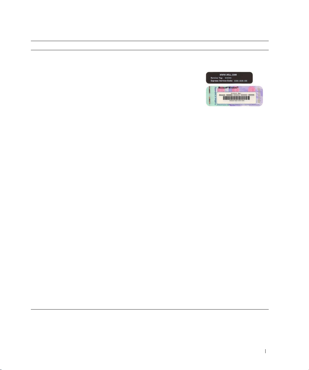
Service Tag and Microsoft® Windows® Product Key
These labels are located on your computer.
• Use the Service
Tag to identify
your computer
when you use
support.dell.co
or contact
m
support.
• Enter the Express Service Code to direct your call
when contacting support.
• Solutions — Troubleshooting hints and tips, articles
from technicians, online courses, and frequently asked
questions
Dell Support Website — support.dell.com
NOTE: Select your region or business segment to
view the appropriate support site.
• Community — Online discussion with other Dell
customers
• Upgrades — Upgrade information for components, such
as the memory, hard drive, and operating system
• Customer Care — Contact information, service call and
order status, and warranty and repair information
• Service and support — Service call status, support
history, service contract, and online discussions with
support
• Reference — Computer documentation, details on my
computer configuration, product specifications, and
white papers
• Downloads — Certified drivers, patches, and software
updates
• Desktop System Software (DSS)— If you reinstall the
operating system on your computer, you should also
reinstall the DSS utility. DSS automatically detects your
computer and operating system and installs the updates
appropriate for your configuration, providing critical
updates for your operating system and support for Dell™
3.5-inch USB floppy drives, Intel
®
processors, optical
drives, and USB devices. DSS is necessary for correct
operation of your Dell computer.
To download Desktop System Software:
1
Go to
support.dell.com
business segment, then enter your Service Tag.
2
Select
3
Click your operating system, and then search for
the keyword
NOTE: The support.dell.com user interface may vary
depending on your selections.
, select your region or
Drivers & Downloads
Desktop System Software
, then click Go.
.
Quick Reference Guide 7
Page 8

System Views
Mini Tower Computer — Front View
1
2
3
11
10
9
4
5
6
7
8
8 Quick Reference Guide
Page 9

1 5.25-inch drive bay Can contain an optical drive. Insert a CD or DVD (if supported) into this drive.
2 5.25-inch drive bay Can contain an optical drive. Insert a CD or DVD (if supported) into this drive.
3 3.5-inch drive bay Can contain an optional floppy drive or optional media card reader.
4 USB 2.0 connectors (2) Use the front USB connectors for devices that you connect occasionally, such as
joysticks or cameras, or for bootable USB devices (see your online User’s Guide for
more information on booting to a USB device).
It is recommended that you use the back USB connectors for devices that typically
remain connected, such as printers and keyboards.
5 LAN indicator light This light indicates that a LAN (local area network) connection is established.
6 diagnostic lights Use the lights to help you troubleshoot a computer problem based on the diagnostic
code. For more information, see "Diagnostic Lights" on page 50.
7 power button Press this button to turn on the computer.
NOTICE: To avoid losing data, do not turn off the computer by pressing the power
button. Instead, perform an operating system shutdown. See "Before You Begin" on
page 25 for more information.
NOTICE: If your operating system has ACPI enabled, when you press the power
button the computer will perform an operating system shutdown.
8 power light The power light illuminates and blinks or remains solid to indicate different operating
modes:
• No light — The computer is turned off.
• Steady green — The computer is in a normal operating state.
• Blinking green — The computer is in a power-saving mode.
• Blinking or solid amber — See
To exit from a power-saving mode, press the power button or use the keyboard or the
mouse if it is configured as a wake device in the Windows Device Manager. For more
information about sleep modes and exiting from a power-saving mode, see your online
User’s Guide.
See "System Lights" on page 49 for a description of light codes that can help you
troubleshoot problems with your computer.
9 hard-drive activity light This light flickers when the hard drive is being accessed.
10 headphone connector Use the headphone connector to attach headphones and most kinds of speakers.
11 microphone connector Use the microphone connector to attach a microphone.
your online User’s Guide
.
Quick Reference Guide 9
Page 10
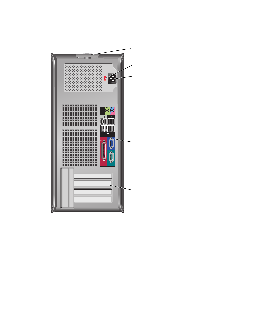
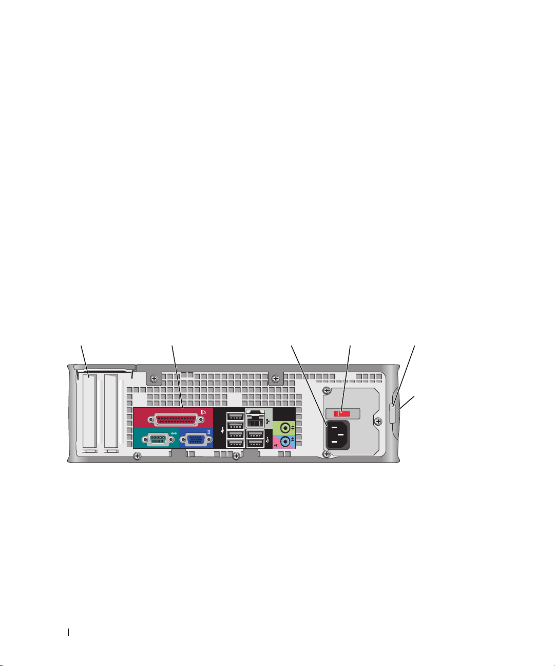
Mini Tower Computer — Back View
1
2
3
4
5
6
1 cover-release latch This latch allows you to open the computer cover.
2 padlock ring Insert a padlock to lock the computer cover.
10 Quick Reference Guide
Page 11
3 voltage selection switch Your computer is equipped with a manual voltage-selection switch.
To help avoid damaging a computer with a manual voltage-selection switch, set the
switch for the voltage that most closely matches the AC power available in your
location.
NOTICE: The voltage selection switch must be set to the 115-V position even
though the AC power available in Japan is 100 V.
Also, ensure that your monitor and attached devices are electrically rated to operate
with the AC power available in your location.
4 power connector Insert the power cable.
5 back-panel connectors Plug serial, USB, and other devices into the appropriate connectors (see "Mini
Tower Computer — Back-Panel Connectors" on page 11).
6 card slots Access connectors for any installed PCI and PCI Express cards.
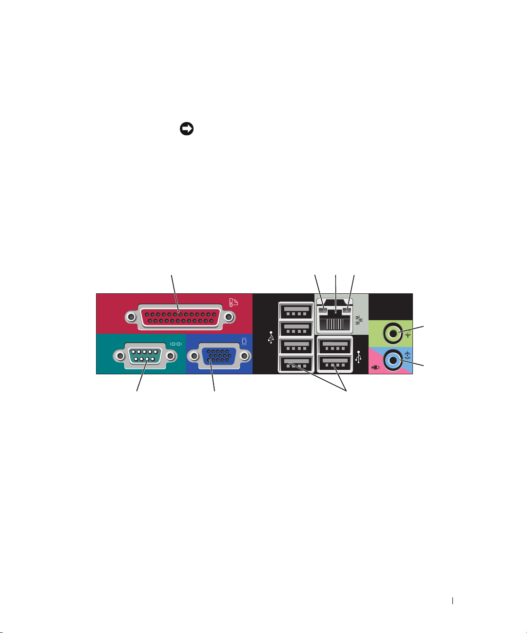
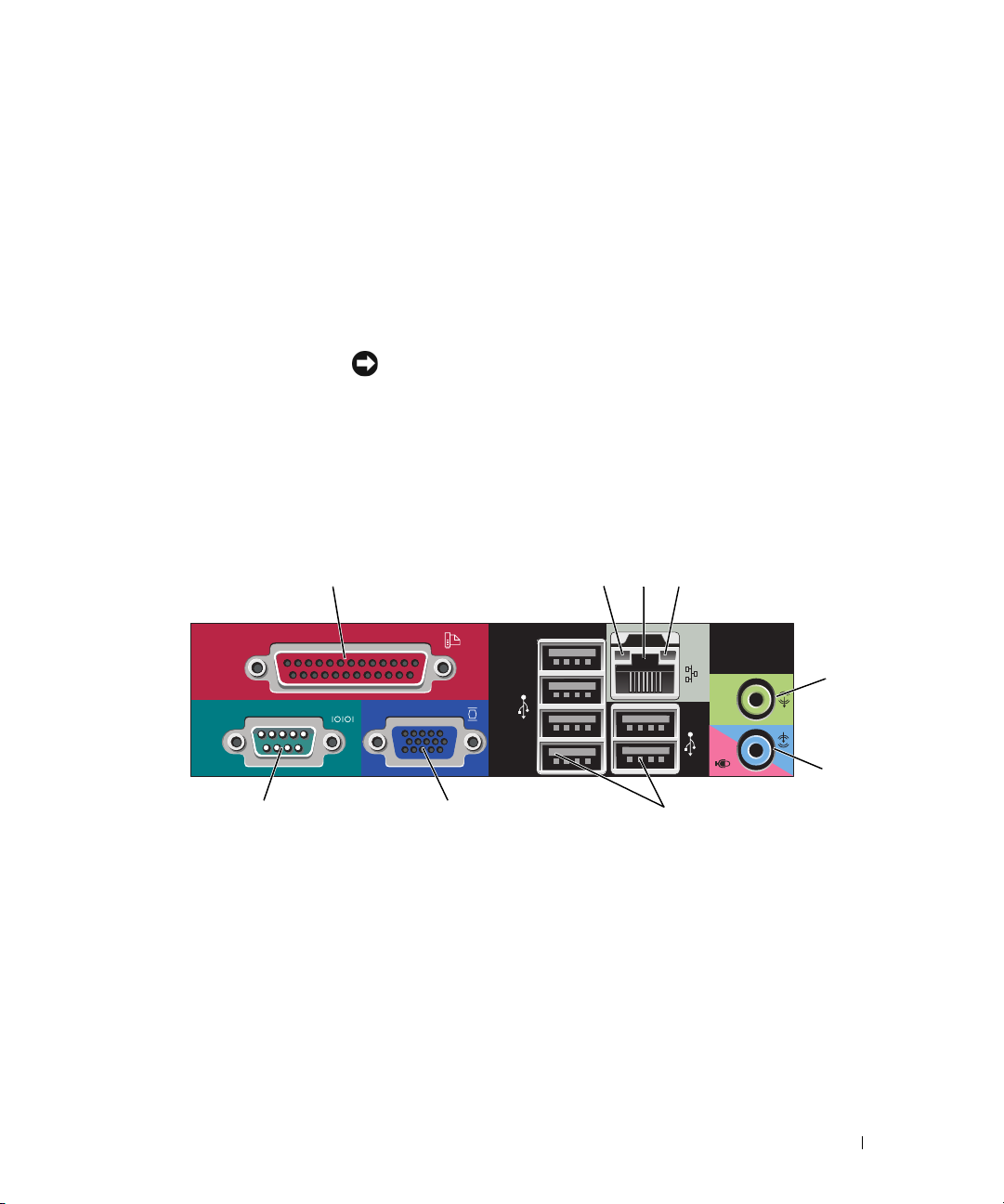
Mini Tower Computer — Back-Panel Connectors
13
98 7
1 parallel connector Connect a parallel device, such as a printer, to the parallel connector. If you have a
USB printer, plug it into a USB connector.
24
5
6
NOTE: The integrated parallel connector is automatically disabled if the computer
detects an installed card containing a parallel connector configured to the same
address. For more information, see your online User’s Guide.
2 link integrity light
• Green — A good connection exists between a 10-Mbps network and the
computer.
• Orange — A good connection exists between a 100-Mbps network and the
computer.
• Yellow — A good connection exists between a 1-Gbps (or 1000-Mbps) network
and the computer.
• Off — The computer is not detecting a physical connection to the network.
Quick Reference Guide 11
Page 12

3 network adapter
connector
To attach your computer to a network or broadband device, connect one end of a
network cable to either a network jack or your network or broadband device.
Connect the other end of the network cable to the network adapter connector on
the back panel of your computer. A click indicates that the network cable has been
securely attached.
NOTE: Do not plug a telephone cable into the network connector.
On computers with a network connector card, use the connector on the card.
It is recommended that you use Category 5 wiring and connectors for your
network. If you must use Category 3 wiring, force the network speed to 10 Mbps to
ensure reliable operation.
4 network activity light Flashes a yellow light when the computer is transmitting or receiving network
data. A high volume of network traffic may make this light appear to be in a steady
"on" state.
5 line-out connector Use the green line-out connector to attach most speakers with integrated
amplifiers.
6 line-in/microphone
connector
7 USB 2.0 connectors (6) Use the back USB connectors for devices that typically remain connected, such as
8 video connector Plug the cable from your VGA-compatible monitor into the blue connector.
Use the blue and pink line-in/microphone connector to attach a record/playback
device such as a cassette player, CD player, or VCR.; or a personal computer
microphone for voice or musical input into a sound or telephony program.
printers and keyboards.
NOTE: If you purchased an optional graphics card, this connector will be covered by
a cap. Connect your monitor to the connector on the graphics card. Do not remove
the cap.
NOTE: If you are using a graphics card that supports dual monitors, use the y-cable
that came with your computer.
9 serial connector Connect a serial device, such as a handheld device, to the serial port. The default
designations are COM1 for serial connector 1 and COM2 for serial connector 2.
For more information, see your online User’s Guide.
12 Quick Reference Guide
Page 13
Desktop Computer — Front View
2
89
7
1 USB 2.0 connectors (2) Use the front USB connectors for devices that you connect occasionally, such as
joysticks or cameras, or for bootable USB devices (see your online User’s Guide for
more information about booting to a USB device).
It is recommended that you use the back USB connectors for devices that typically
remain connected, such as printers and keyboards.
2 LAN indicator light This light indicates that a LAN (local area network) connection is established.
3 power button Press this button to turn on the computer.
NOTICE: To avoid losing data, do not turn off the computer by pressing the
power button. Instead, perform an operating system shutdown. See "Before You
Begin" on page 25 for more information.
3
514611 10
NOTICE: If your operating system has ACPI enabled, when you press the
power button the computer will perform an operating system shutdown.
4 Dell badge This badge can be rotated to match the orientation of your computer. To rotate,
place fingers around the outside of the badge, press firmly, and turn the badge. You
can also rotate the badge using the slot provided near the bottom of the badge.
Quick Reference Guide 13
Page 14
5 power light The power light illuminates and blinks or remains solid to indicate different
operating states:
• No light — The computer is turned off.
• Steady green — The computer is in a normal operating state.
• Blinking green — The computer is in a power-saving mode.
• Blinking or solid amber — See
To exit from a power-saving mode, press the power button or use the keyboard or
the mouse if it is configured as a wake device in the Windows Device Manager. For
more information about sleep modes and exiting from a power-saving mode, see
your online User’s Guide.
See "System Lights" on page 49 for a description of light codes that can help you
troubleshoot problems with your computer.
6 diagnostic lights Use the lights to help you troubleshoot a computer problem based on the
diagnostic code. For more information, see "Diagnostic Lights" on page 50.
7 hard-drive activity light This light flickers when the hard drive is being accessed.
8 headphone connector Use the headphone connector to attach headphones and most kinds of speakers.
9 microphone connector Use the microphone connector to attach a microphone.
10 3.5-inch drive bay Can contain an optional floppy drive or optional Media Card Reader.
11 5.25-inch drive bay Can contain an optical drive. Insert a CD or DVD (if supported) into this drive.
your online User’s Guide
.
Desktop Computer — Back View
1
14 Quick Reference Guide
2 3 4 6
5
Page 15

1 card slots Access connectors for any installed PCI and PCI Express cards.
2 back-panel connectors Plug serial, USB, and other devices into the appropriate connectors (see "Desktop
Computer — Back-Panel Connectors" on page 15).
3 power connector Insert the power cable.
4 voltage selection switch Your computer is equipped with a manual voltage selection switch.
To help avoid damaging a computer with a manual voltage selection switch, set
the switch for the voltage that most closely matches the AC power available in
your location.
NOTICE: The voltage selection switch must be set to the 115-V position even
though the AC power available in Japan is 100 V.
Also, ensure that your monitor and attached devices are electrically rated to
operate with the AC power available in your location.
5 padlock ring Insert a padlock to lock the computer cover.
6 cover-release latch Allows you to open the computer cover.
Desktop Computer — Back-Panel Connectors
13
98 7
24
5
6
Quick Reference Guide 15
Page 16

1 parallel connector Connect a parallel device, such as a printer, to the parallel connector. If you have a
USB printer, plug it into a USB connector.
NOTE: The integrated parallel connector is automatically disabled if the computer
detects an installed card containing a parallel connector configured to the same
address. For more information, see your online User’s Guide.
2 link integrity light
3 network adapter
connector
• Green — A good connection exists between a 10-Mbps network and the
computer.
• Orange — A good connection exists between a 100-Mbps network and the
computer.
• Yellow — A good connection exists between a 1-Gbps (or 1000-Mbps) network
and the computer.
• Off — The computer is not detecting a physical connection to the network.
To attach your computer to a network or broadband device, connect one end of a
network cable to either a network jack or your network or broadband device.
Connect the other end of the network cable to the network adapter connector on
the back panel of your computer. A click indicates that the network cable has been
securely attached.
NOTE: Do not plug a telephone cable into the network connector.
On computers with a network connector card, use the connector on the card.
It is recommended that you use Category 5 wiring and connectors for your
network. If you must use Category 3 wiring, force the network speed to 10 Mbps to
ensure reliable operation.
4 network activity light Flashes a yellow light when the computer is transmitting or receiving network
data. A high volume of network traffic may make this light appear to be in a steady
"on" state.
5 line-out connector Use the green line-out connector to attach most speakers with integrated
amplifiers.
6 line-in/microphone
connector
7 USB 2.0 connectors (6) Use the back USB connectors for devices that typically remain connected, such as
8 video connector Plug the cable from your VGA-compatible monitor into the blue connector.
Use the blue and pink line-in/microphone connector to attach a record/playback
device such as a cassette player, CD player, or VCR.; or a personal computer
microphone for voice or musical input into a sound or telephony program.
printers and keyboards.
NOTE: If you purchased an optional graphics card, this connector will be covered by
a cap. Connect your monitor to the connector on the graphics card. Do not remove
the cap.
NOTE: If you are using a graphics card that supports dual monitors, use the y-cable
that came with your computer.
9 serial connector Connect a serial device, such as a handheld device, to the serial port. The default
designations are COM1 for serial connector 1 and COM2 for serial connector 2.
For more information, see your online User’s Guide.
16 Quick Reference Guide
Page 17
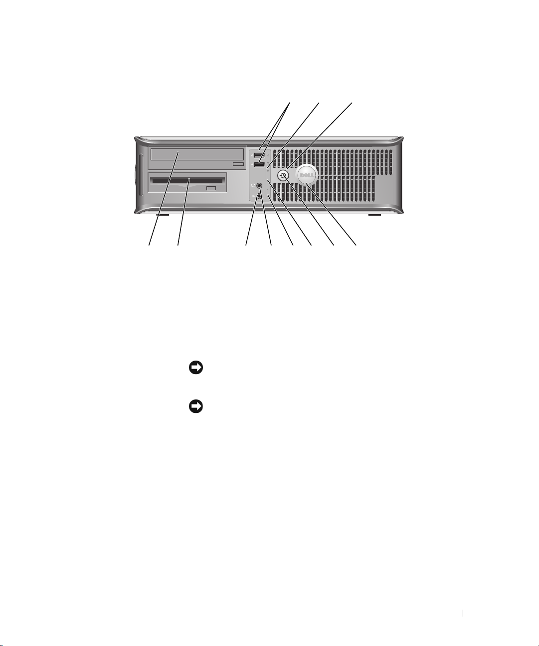
Small Form Factor Computer — Front View
2
1
11 10
1 USB 2.0 connectors (2) Use the front USB connectors for devices that you connect occasionally, such as
joysticks or cameras, or for bootable USB devices (see your online User’s Guide for
more information about booting to a USB device).
It is recommended that you use the back USB connectors for devices that typically
remain connected, such as printers and keyboards.
2 power button Press to turn on the computer.
NOTICE: To avoid losing data, do not turn off the computer by pressing the
power button. Instead, perform an operating system shutdown. See "Before You
Begin" on page 25 for more information.
89
7
3
4
5
6
NOTICE: If your operating system has ACPI enabled, when you press the
power button the computer will perform an operating system shutdown.
3 Dell badge Can be rotated to match the orientation of your computer. To rotate, place fingers
around the outside of the badge, press firmly, and turn the badge. You can also
rotate the badge using the slot provided near the bottom of the badge.
4 LAN indicator light Indicates that a LAN (local area network) connection is established.
5 diagnostic lights Use the lights to help you troubleshoot a computer problem based on the
diagnostic code. For more information, see "Diagnostic Lights" on page 50.
6 hard drive activity light This light flickers when the hard drive is being accessed.
Quick Reference Guide 17
Page 18
7 power light The power light illuminates and blinks or remains solid to indicate different
operating states:
• No light — The computer is turned off.
• Steady green — The computer is in a normal operating state.
• Blinking green — The computer is in a power-saving mode.
• Blinking or solid amber — See
To exit from a power-saving mode, press the power button or use the keyboard or
the mouse if it is configured as a wake device in the Windows Device Manager. For
more information about sleep modes and exiting from a power-saving mode, see
your online User’s Guide.
See "System Lights" on page 49 for a description of light codes that can help you
troubleshoot problems with your computer.
8 headphone connector Use the headphone connector to attach headphones and most kinds of speakers.
9 microphone connector Use the microphone connector to attach a microphone.
10 3.5-inch drive bay Can contain an optional floppy drive or optional media card reader.
11 5.25-inch drive bay Can contain an optical drive. Insert a CD or DVD (if supported) into this drive.
your online User’s Guide
.
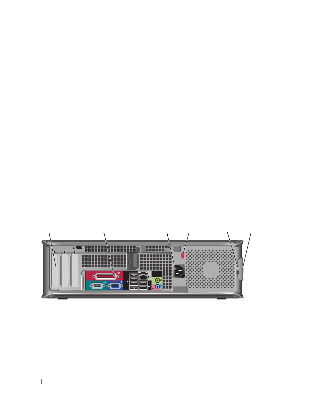
Small Form Factor Computer — Back View
51 2 3 4
18 Quick Reference Guide
6
Page 19
1 card slots Access connectors for any installed PCI and PCI Express cards.
2 back-panel connectors Plug serial, USB, and other devices into the appropriate connectors (see "Small
Form Factor Computer — Back-Panel Connectors" on page 19).
3 power connector Insert the power cable.
4 voltage selection switch Your computer is equipped with a manual voltage-selection switch.
To help avoid damaging a computer with a manual voltage selection switch, set
the switch for the voltage that most closely matches the AC power available in
your location.
NOTICE: The voltage selection switch must be set to the 115-V position even
though the AC power available in Japan is 100 V.
Also, ensure that your monitor and attached devices are electrically rated to
operate with the AC power available in your location.
5 padlock ring Insert a padlock to lock the computer cover.
6 cover release latch Allows you to open the computer cover.
Small Form Factor Computer — Back-Panel Connectors
13
98 7
24
5
6
Quick Reference Guide 19
Page 20

1 parallel connector Connect a parallel device, such as a printer, to the parallel connector. If you have a
USB printer, plug it into a USB connector.
NOTE: The integrated parallel connector is automatically disabled if the computer
detects an installed card containing a parallel connector configured to the same
address. For more information, see your online User’s Guide.
2 link integrity light
3 network adapter
connector
• Green — A good connection exists between a 10-Mbps network and the
computer.
• Orange — A good connection exists between a 100-Mbps network and the
computer.
• Yellow — A good connection exists between a 1-Gbps (or 1000-Mbps) network
and the computer.
• Off — The computer is not detecting a physical connection to the network.
To attach your computer to a network or broadband device, connect one end of a
network cable to either a network jack or your network or broadband device.
Connect the other end of the network cable to the network adapter connector on
the back panel of your computer. A click indicates that the network cable has been
securely attached.
NOTE: Do not plug a telephone cable into the network connector.
On computers with a network connector card, use the connector on the card.
It is recommended that you use Category 5 wiring and connectors for your
network. If you must use Category 3 wiring, force the network speed to 10 Mbps to
ensure reliable operation.
4 network activity light Flashes a yellow light when the computer is transmitting or receiving network
data. A high volume of network traffic may make this light appear to be in a steady
"on" state.
5 line-out connector Use the green line-out connector (available on computers with integrated sound)
to attach most speakers with integrated amplifiers.
6 line-in/microphone
connector
7 USB 2.0 connectors (6) Use the back USB connectors for devices that typically remain connected, such as
Use the blue and pink line-in/microphone connector (available on computers with
integrated sound) to attach a record/playback device such as a cassette player, CD
player, or VCR; or a personal computer microphone for voice or musical input into
a sound or telephony program.
printers and keyboards.
20 Quick Reference Guide
Page 21
8 video connector Plug the cable from your VGA-compatible monitor into the blue connector.
NOTE: If you purchased an optional graphics card, this connector will be covered by
a cap. Connect your monitor to the connector on the graphics card. Do not remove
the cap.
NOTE: If you are using a graphics card that supports dual monitors, use the y-cable
that came with your computer.
9 serial connector Connect a serial device, such as a handheld device, to the serial port. The default
designations are COM1 for serial connector 1 and COM2 for serial connector 2.
For more information, see your online User’s Guide.
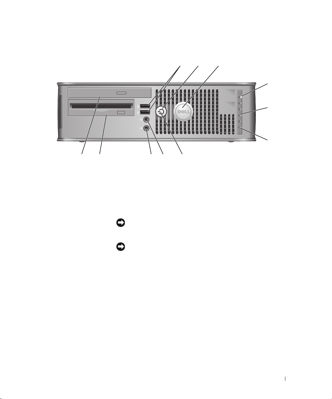
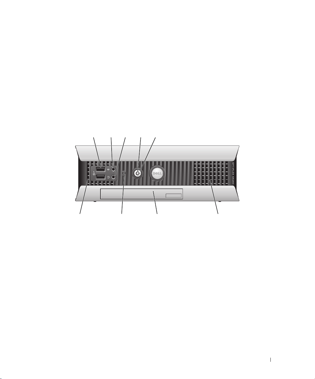
Ultra-Small Form Factor Computer — Front View
12345
896
1 USB connectors (2) Use the front USB connectors for devices that you connect occasionally, such as
joysticks or cameras, or for bootable USB devices (see your online User’s Guide for
more information about booting to a USB device).
It is recommended that you use the back USB connectors for devices that typically
remain connected, such as printers and keyboards.
2 headphone connector Use the headphone connector to attach headphones and most kinds of speakers.
3 microphone connector Use the microphone connector to attach a microphone.
7
Quick Reference Guide 21
Page 22
4 power light The power light illuminates and blinks or remains solid to indicate different states:
• No light — The computer is turned off.
• Steady green — The computer is in a normal operating state.
• Blinking green — The computer is in a power-saving mode.
• Blinking or solid yellow — See
To exit from a power-saving mode, press the power button or use the keyboard or
the mouse if it is configured as a wake device in the Windows Device Manager. For
more information about sleep modes and exiting from a power-saving mode, see
your online User’s Guide.
See "System Lights" on page 49 for a description of light codes that can help you
troubleshoot problems with your computer.
5 power button Press this button to turn on the computer.
NOTICE: To avoid losing data, do not turn off the computer by pressing the
power button. Instead, perform an operating system shutdown. See "Before You
Begin" on page 25 for more information.
6 vents The vents help prevent your computer from overheating. To ensure proper
ventilation, do not block these cooling vents.
7 module bay Install a D-module optical drive, second hard drive, or floppy drive in the module
bay.
8 hard-drive access light The hard-drive access light is on when the computer reads data from or writes data
to the hard drive. The light might also be on when devices such as your CD player
are operating.
9 vents The vents help prevent your computer from overheating. To ensure proper
ventilation, do not block these cooling vents.
your online User’s Guide
.
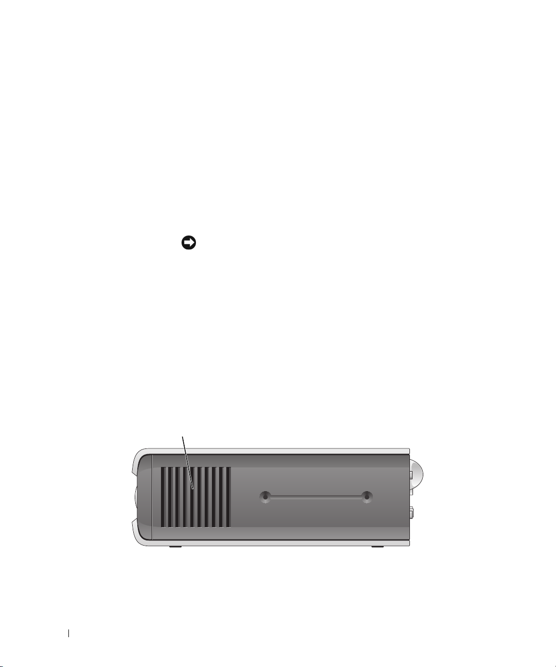
Ultra-Small Form Factor Computer — Side View
1
1 vents The vents located on each side of the computer help prevent your computer from
overheating. To ensure proper ventilation, do not block these cooling vents.
22 Quick Reference Guide
Page 23
Ultra-Small Form Factor Computer — Back View
231
5
1 diagnostic lights See "Diagnostic Lights" on page 50 for a description of light codes
2 computer cover release knob Rotate this knob in a clockwise direction to remove the cover.
3 back-panel connectors The connectors for your computer (see "Ultra-Small Form Factor
4 power connector Insert the power cable.
5 vents The vents help prevent your computer from overheating. To ensure
4
that can help you troubleshoot problems with your computer.
Computer — Back-Panel Connectors" on page 23).
proper ventilation, do not block these cooling vents.
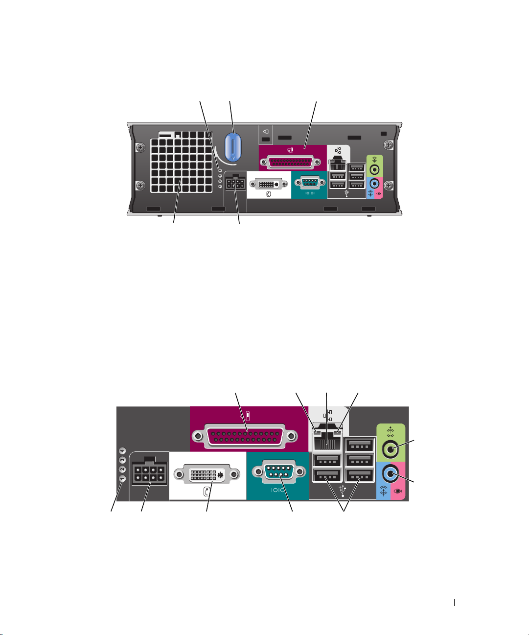
Ultra-Small Form Factor Computer — Back-Panel Connectors
2134
5
6
10 7811
1 parallel connector Connect a parallel device, such as a printer, to the parallel connector. If you have a USB
printer, plug it into a USB connector.
9
Quick Reference Guide 23
Page 24

2 link integrity light
3 network adapter To attach your computer to a network or broadband device, connect one end of a
• Green — A good connection exists between a 10-Mbps network and the computer.
• Orange — A good connection exists between a 100-Mbps network and the computer.
• Yellow — A good connection exists between a 1000-Mbps (1-Gbps) network and the
computer.
• Off — The computer is not detecting a physical connection to the network or the
network controller is turned off in system setup.
network cable to either a network jack or your network or broadband device. Connect
the other end of the network cable to the network adapter connector on the back panel
of your computer. A click indicates that the network cable has been securely attached.
NOTE: Do not plug a telephone cable into the network connector.
On computers with a network connector card, use the connector on the card.
It is recommended that you use Category 5 wiring and connectors for your network. If
you must use Category 3 wiring, force the network speed to 10 Mbps to ensure reliable
operation.
4 network activity light The amber light flashes when the computer is transmitting or receiving network data. A
high volume of network traffic may make this light appear to be in a steady "on" state.
5 line-out connector Use the green line-out connector to attach an amplified speaker set.
6 line-in/ microphone
connector
7 USB connectors (5) Use the back USB connectors for devices that typically remain connected, such as
8 serial connector Connect a serial device, such as a handheld device, to the serial connector.
9 video connector If you have a DVI-compatible monitor, plug the cable from your monitor into the white
10 power connector The connector for the power adapter.
11 diagnostic lights See "Diagnostic Lights" on page 50 for a description of light codes that can help you
Use the blue and pink line-in/ microphone connector to attach a record/playback device
such as a cassette player, CD player, or VCR.; or a personal computer microphone for
voice or musical input into a sound or telephony program.
printers and keyboards.
connector on the back panel.
If you have a VGA monitor, see "Connecting a VGA Monitor" in your computer User’s
Guide.
troubleshoot problems with your computer.
Removing the Computer Cover
CAUTION: Before you begin any of the procedures in this section, follow the safety instructions in the Product
Information Guide.
CAUTION: To guard against electrical shock, always unplug your computer from the electrical outlet before
removing the cover.
24 Quick Reference Guide
Page 25

Before You Begin
NOTICE: To avoid losing data, save and close any open files and exit any open programs before you turn off your
computer.
1
Shut down the operating system:
a
Save and close any open files, exit any open programs, click the
Off Computer
b
In the
Turn off computer
.
window, click
Tur n o ff
.
The computer turns off after the operating system shutdown process finishes.
2
Ensure that the computer and any attached devices are turned off. If your computer and attached
devices did not automatically turn off when you shut down your operating system, turn them off now.
Before Working Inside Your Computer
Use the following safety guidelines to help protect your computer from potential damage and to help
ensure your own personal safety.
CAUTION: Before you begin any of the procedures in this section, follow the safety instructions in the Product
Information Guide.
CAUTION: Handle components and cards with care. Do not touch the components or contacts on a card. Hold a
card by its edges or by its metal mounting bracket. Hold a component such as a processor by its edges, not by
its pins.
NOTICE: Only a certified service technician should perform repairs on your computer. Damage due to servicing
that is not authorized by Dell is not covered by your warranty.
Start
button, and then click
Tu r n
NOTICE: When you disconnect a cable, pull on its connector or on its strain-relief loop, not on the cable itself.
Some cables have a connector with locking tabs; if you are disconnecting this type of cable, press in on the locking
tabs before you disconnect the cable. As you pull connectors apart, keep them evenly aligned to avoid bending any
connector pins. Also, before you connect a cable, ensure that both connectors are correctly oriented and aligned.
To avoid damaging the computer, perform the following steps before you begin working inside the
computer.
1
Turn off your computer.
NOTICE: To disconnect a network cable, first unplug the cable from your computer and then unplug it from the
network wall jack.
2
Disconnect any telephone or telecommunication lines from the computer.
3
Disconnect your computer and all attached devices from their electrical outlets, and then press the
power button to ground the system board.
4
If applicable, remove the computer stand (for instructions, see the documentation that came with the
stand).
CAUTION: To guard against electrical shock, always unplug your computer from the electrical outlet before
removing the cover.
Quick Reference Guide 25
Page 26

5
Remove the computer cover:
• Remove the mini tower computer cover (see "Mini Tower Computer" on page 26).
• Remove the desktop computer cover (see "Desktop Computer" on page 27).
• Remove the small form factor computer cover (see "Small Form Factor Computer" on page 28).
• Remove the ultra-small form factor computer cover (see "Ultra-Small Form Factor Computer" on
page 30).
NOTICE: Before touching anything inside your computer, ground yourself by touching an unpainted metal surface,
such as the metal at the back of the computer. While you work, periodically touch an unpainted metal surface to
dissipate any static electricity that could harm internal components.
Mini Tower Computer
CAUTION: Before you begin any of the procedures in this section, follow the safety instructions in the Product
Information Guide.
CAUTION: To guard against electrical shock, always unplug your computer from the electrical outlet before
removing the computer cover.
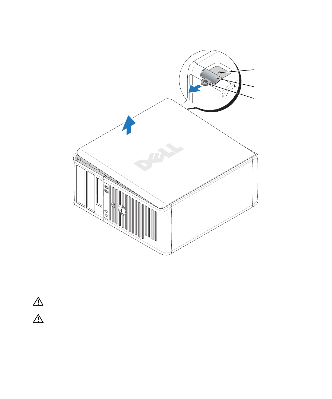
1
Follow the procedures in "Before You Begin" on page 25.
2
Lay the computer on its side as shown in the illustration.
3
Locate the cover release latch shown in the illustration. Then, slide the release latch back as you lift the
cover.
4
Grip the sides of the computer cover and pivot the cover up using the hinge tabs as leverage points.
5
Remove the cover from the hinge tabs and set it aside on a soft nonabrasive surface.
CAUTION: Graphic card heatsinks may become very hot during normal operation. Ensure that a graphic card
heatsink has had sufficient time to cool before you touch it.
26 Quick Reference Guide
Page 27
1
2
3
1 security cable slot 2 cover release latch 3 padlock ring
Desktop Computer
CAUTION: Before you begin any of the procedures in this section, follow the safety instructions in the Product
Information Guide.
CAUTION: To guard against electrical shock, always unplug your computer from the electrical outlet before
removing the computer cover.
1
Follow the procedures in "Before You Begin" on page 25.
2
If you have installed a padlock through the padlock ring on the back panel, remove the padlock.
Quick Reference Guide 27
Page 28
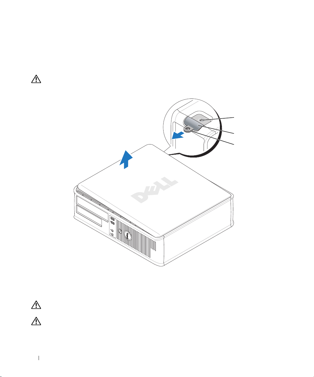
3
Locate the cover release latch shown in the illustration. Then, slide the release latch back as you lift the
cover.
4
Grip the sides of the computer cover and pivot the cover up using the hinge tabs as leverage points.
5
Remove the cover from the hinge tabs and set it aside on a soft nonabrasive surface.
CAUTION: Graphic card heatsinks may become very hot during normal operation. Ensure that a graphic card
heatsink has had sufficient time to cool before you touch it.
1
2
3
1 security cable slot 2 cover release latch 3 padlock ring
Small Form Factor Computer
CAUTION: Before you begin any of the procedures in this section, follow the safety instructions in the Product
Information Guide.
CAUTION: To guard against electrical shock, always unplug your computer from the electrical outlet before
removing the computer cover.
28 Quick Reference Guide
Page 29
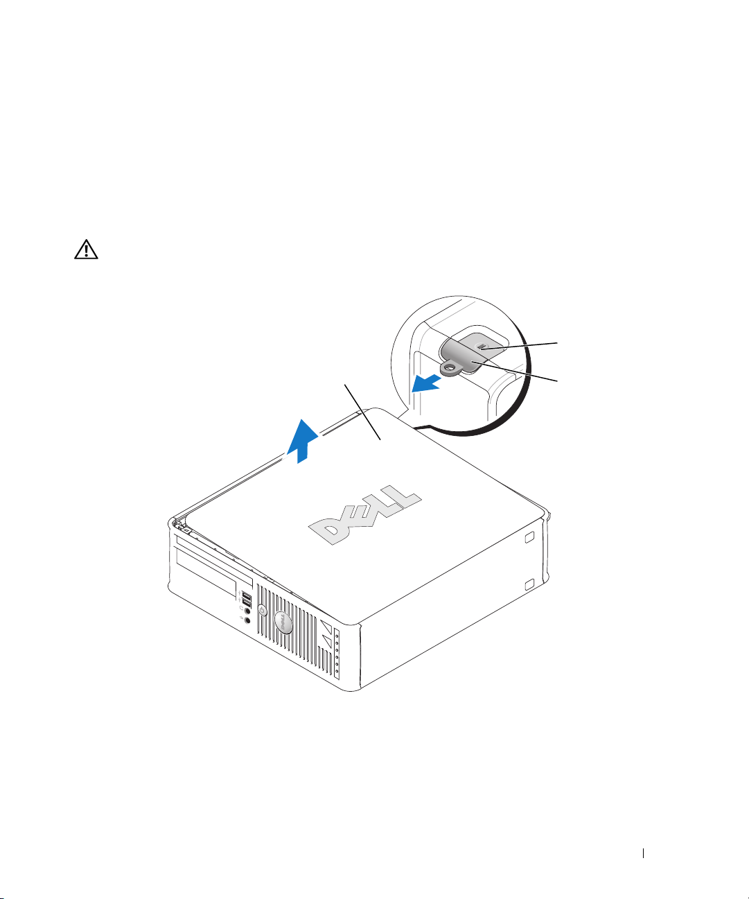
1
Follow the procedures in "Before You Begin" on page 25.
2
If you have installed a padlock through the padlock ring on the back panel, remove the padlock.
3
Locate the cover release latch shown in the illustration. Then, slide the release latch back as you lift the
cover.
4
Grip the sides of the computer cover and pivot the cover up using the bottom hinges as leverage
points.
5
Remove the cover from the hinge tabs and set it aside on a soft nonabrasive surface.
CAUTION: Graphic card heatsinks may become very hot during normal operation. Ensure that a graphic card
heatsink has had sufficient time to cool before you touch it.
1
3
1 security cable slot 2 cover release latch 3 computer cover
2
Quick Reference Guide 29
Page 30
Ultra-Small Form Factor Computer
CAUTION: Before you begin any of the procedures in this section, follow the safety instructions in the Product
Information Guide.
CAUTION: To guard against electrical shock, always unplug your computer from the electrical outlet before
removing the computer cover.
1
Follow the procedures in "Before You Begin" on page 25.
NOTICE: Before touching anything inside your computer, ground yourself by touching an unpainted metal surface.
While you work, periodically touch an unpainted metal surface to dissipate any static electricity that could harm
internal components.
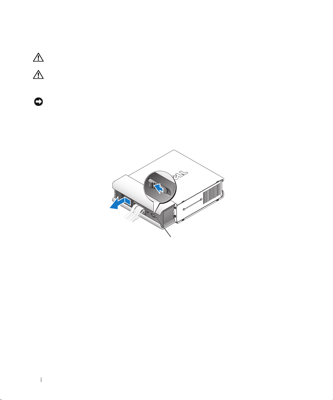
2
If applicable, remove the cable cover.
a
If a security device is installed in the security cable slot, remove the device.
b
Press on the release button, grasp the cable cover, and slide the cover to the left until it stops, and
then lift the cable cover up and away.
3
Remove the computer cover:
a
Rotate the cover release knob in a clockwise direction, as shown in the illustration.
b
Slide the computer cover forward by 1 cm (½ inch), or until it stops, and then raise the cover.
30 Quick Reference Guide
1
1 release button
Page 31

CAUTION: Graphic card heatsinks may become very hot during normal operation. Ensure that a graphic card
heatsink has had sufficient time to cool before you touch it.
1
1 release knob
Quick Reference Guide 31
Page 32

Inside Your Computer
Mini Tower Computer
2
1
3
4
5
6
7
1 optical drive 2 floppy drive or media card
reader
4 optional chassis-intrusion
switch
7 hard drive
5 system board 6 heat-sink assembly
32 Quick Reference Guide
3 power supply
Page 33

System Board Components
21
20
19
18
17
16
15
14
12
3
4
5
6
7
8
13
12
11
10
9
Quick Reference Guide 33
Page 34

1 fan connector (FAN) 12 battery socket (BATT)
2 processor connector (CPU) 13 PCI Express x16 connector (SLOT1)
3 processor power connector (12VPOWER) 14 PCI Express x1 connector (SLOT4)
4 memory module connectors (DIMM_1,
DIMM_2, DIMM_3, DIMM_4)
5 RTC reset jumper (RTCRST) 16 PCI connector (SLOT3)
6 password jumper (PSWD) 17 serial connector (SER2)
7 SATA drive connectors (SATA0, SATA1, SATA4,
SATA5)
8 front-panel connector (FNT_PANEL) 19 flea power
9 power connector (POWER) 20 system board speaker (BEEP)
10 intrusion switch connector (INTRUDER) 21 speaker connector (INT_SPKR)
11 internal USB (INTERNAL_USB)
15 PCI connector (SLOT2)
18 floppy drive connector (DSKT)
Jumper Settings
34 Quick Reference Guide
Page 35

Jumper Setting Description
PSWD Password features are enabled
(default setting).
Password features are disabled.
RTCRST The real-time clock has not been
reset.
jumpered unjumpered
The real-time clock is being reset
(jumpered temporarily).
Desktop Computer
2
1
7
1 drive bays (media card reader
or floppy drive, optical drive
and hard drive)
4 system board 5 card slots 6 heat sink assembly
7 front I/O panel
2 power supply 3 optional chassis-intrusion
3
4
5
6
switch
Quick Reference Guide 35
Page 36

System Board Components
12
20
19
18
17
16
15
14
3
4
5
6
7
8
13
36 Quick Reference Guide
12
91011
Page 37

1 internal speaker (INT_SPKR) 11 intrusion switch connector (INTRUDER)
2 processor connector (CPU) 12 battery socket (BATT)
3 processor power connector (12VPOWER) 13 PCI Express x16 connector (SLOT1)
4 memory module connectors (DIMM_1,
14 PCI connector (SLOT3)
DIMM_2, DIMM_3, DIMM_4)
5 RTC reset jumper (RTCRST) 15 PCI connector (SLOT2)
6 password jumper (PSWD) 16 serial connector (SER2)
7 SATA connectors (SATA0, SATA1) 17 floppy drive connector (DSKT)
8 front-panel connector (FNT_PANEL) 18 flea power
9 power connector (POWER) 19 system board speaker (BEEP)
10 internal USB (INTERNAL_USB) 20 fan connector (FAN)
Jumper Settings
Jumper Setting Description
PSWD Password features are enabled
(default setting).
Password features are disabled.
RTCRST The real-time clock has not been
reset.
The real-time clock is being reset
(jumpered temporarily).
jumpered unjumpered
Quick Reference Guide 37
Page 38

Small Form Factor Computer
3
2
1
1 drive-release latch 2 optical drive 3 power supply and fan
4 optional chassis-intrusion
switch
7 heat sink and blower
assembly
5 hard drive 6 system board
4
5
6
7
38 Quick Reference Guide
Page 39

System Board Components
12
20
19
18
17
16
15
3
4
5
6
7
14
13
12
11
10
9
Quick Reference Guide 39
8
Page 40

1 internal speaker connector (INT_SPKR) 11 intrusion switch connector (INTRUDER)
2 processor connector (CPU) 12 internal USB connector (USB)
3 processor power connector (12VPOWER) 13 battery socket (BATT)
4 memory module connectors (DIMM_1,
DIMM_2, DIMM_3, DIMM_4)
5 RTC reset jumper (RTCRST) 15 PCI connector (SLOT2)
6 password jumper (PSWD) 16 serial connector (SER2)
7 SATA connectors (SATA0, SATA1) 17 floppy drive connector (DSKT)
8 front-panel connector (FNT_PANEL) 18 flea power
9 power connector (POWER) 19 system board speaker (BEEP
10 fan connector (FAN2) 20 fan connector (FAN)
14 PCI Express x16 connector (SLOT1)
Jumper Settings
40 Quick Reference Guide
Page 41

Jumper Setting Description
PSWD Password features are enabled
(default setting).
Password features are disabled.
RTCRST The real-time clock has not been
reset.
jumpered unjumpered
The real-time clock is being reset
(jumpered temporarily).
Ultra-Small Form Factor Computer
1
6
5
1 fan shroud/ heat sink
assembly
4 hard drive 5 security cable slot 6 chassis intrusion switch
2 speaker (optional) 3 memory modules (2)
2
3
4
Quick Reference Guide 41
Page 42

System Board Components
12 34
14
13
5
6
7
8
12
11
1 fan connector (FAN_FRONT) 8 clear CMOS jumper (RTCRST)
2 internal speaker connector (INT_SPKR) 9 password jumper (PSWD)
3 system board speaker (BEEP) 10 hard-drive fan connector (FAN_HDD)
4 channel B memory connector (DIMM_2) 11 hard-drive power connector (SATA_PWR)
5 channel A memory connector (DIMM_1) 12 fan connector (FAN_REAR)
6 SATA data cable connector(SATA0) 13 intrusion switch connector (INTRUDER)
7 battery (BATT) 14 processor (CPU)
10
42 Quick Reference Guide
9
Page 43

Jumper Settings
Jumper Setting Description
PSWD Password features are enabled
(default setting).
Password features are disabled.
RTCRST The real-time clock has not been
reset.
jumpered unjumpered
The real-time clock is being reset
(jumpered temporarily).
Setting Up Your Computer
CAUTION: Before performing any of the procedures in this section, follow the safety instructions in Product
Information Guide.
NOTICE: If your computer has an expansion card installed (such as a modem card), connect the appropriate cable
to the card, not to the connector on the back panel.
NOTICE: To help allow the computer to maintain proper operating temperature, ensure that you do not place the
computer too close to a wall or other storage compartment that might prevent air circulation around the chassis.
See your Product Information Guide for more information.
Quick Reference Guide 43
Page 44

NOTE: Before you install any devices or software that did not ship with your computer, read the documentation
that came with the device or software, or contact the vendor to verify that the device or software is compatible
with your computer and operating system.
You must complete all the steps to properly set up your computer. See the appropriate figures that follow
the instructions.
NOTICE: Do not attempt to operate a PS/2 mouse and a USB mouse simultaneously.
1
Connect the keyboard and mouse.
NOTICE: Do not connect a modem cable to the network adapter connector. Voltage from telephone
communications can cause damage to the network adapter
2
Connect the modem or network cable.
Insert the network cable, not the telephone line, into the network connector. If you have an optional
modem, connect the telephone line to the modem.
3
Connect the monitor.
Align and gently insert the monitor cable to avoid bending connector pins. Tighten the thumbscrews
on the cable connectors.
NOTE: Some monitors have the video connector underneath the back of the screen. See the documentation
that came with your monitor for its connector locations.
4
Connect the speakers.
5
Connect power cables to the computer, monitor, and devices and connect the other ends of the power
cables to electrical outlets.
NOTICE: To avoid damaging a computer with a manual voltage-selection switch, set the switch for the voltage that
most closely matches the AC power available in your location.
NOTICE: In Japan, the voltage selection switch must be set to the 115-V position even though the AC power
available in Japan is 100 V.
6
Verify that the voltage selection switch is set correctly for your location.
Your computer has a manual voltage-selection switch. Computers with a voltage selection switch on
the back panel must be manually set to operate at the correct operating voltage.
44 Quick Reference Guide
Page 45

Set Up Your Keyboard and Mouse
Set Up Your Monitor
Quick Reference Guide 45
Page 46

Power Connections
Solving Problems
Dell provides a number of tools to help you if your computer does not perform as expected. For the latest
troubleshooting information available for your computer, see the Dell Support website at
support.dell.com.
If computer problems occur that require help from Dell, write a detailed description of the error, beep
codes, or diagnostics light patterns, record your Express Service Code and Service Tag below, and then
contact Dell from the same location as your computer. For information on contacting Dell, see your
online User’s Guide.
For an example of the Express Service Code and Service Tag, see "Finding Information" in your computer
User’s Guide.
Express Service Code: ___________________________
Service Tag: ___________________________
Dell Diagnostics
CAUTION: Before you begin any of the procedures in this section, follow the safety instructions in the Product
Information Guide.
When to Use the Dell Diagnostics
If you experience a problem with your computer, perform the checks in "Solving Problems" in your online
User’s Guide and run the Dell Diagnostics before you contact Dell for technical assistance. For
information on contacting Dell, see your online User’s Guide.
NOTICE: The Dell Diagnostics works only on Dell™ computers.
46 Quick Reference Guide
Page 47

Enter system setup (see "System Setup" in your online User’s Guide for instructions), review your
computer’s configuration information, and ensure that the device you want to test displays in system
setup and is active.
Start the Dell Diagnostics from either your hard drive or from the optional Drivers and Utilities CD
(ResourceCD).
Starting the Dell Diagnostics From Your Hard Drive
1
Turn on (or restart) your computer.
2
When the DELL logo appears, press <F12> immediately.
NOTE: If you see a message stating that no diagnostics utility partition has been found, run the Dell
Diagnostics from the optional Drivers and Utilities CD (see "Starting the Dell Diagnostics From the Drivers and
Utilities CD" on page 47).
If you wait too long and the operating system logo appears, continue to wait until you see the
Microsoft
®
Windows® desktop. Then shut down your computer and try again.
When the boot device list appears, highlight
3
When the Dell Diagnostics
Starting the Dell Diagnostics From the Drivers and Utilities CD
1
Insert the
2
Shut down and restart the computer.
Drivers and Utilities
Main Menu
CD.
Boot to Utility Partition
appears, select the test you want to run.
and press <Enter>.
When the DELL logo appears, press <F12> immediately.
If you wait too long and the operating system logo appears, continue to wait until you see the
Microsoft Windows desktop. Then shut down your computer and try again.
NOTE: The next steps change the boot sequence for one time only. On the next start-up, the computer boots
according to the devices specified in system setup.
3
When the boot device list appears, highlight the listing for the CD/DVD drive and press <Enter>.
4
Select the listing for the CD/DVD drive option from the CD boot menu.
5
Select the option to boot from the CD/DVD drive from the menu that appears.
6
Ty p e 1 to start the
7
Ty p e 2 to start the Dell Diagnostics.
8
Select
Run the 32 Bit Dell Diagnostics
Drivers and Utilities
CD menu.
from the numbered list. If multiple versions are listed, select
the version appropriate for your computer.
9
When the Dell Diagnostics
Main Menu
appears, select the test you want to run.
Quick Reference Guide 47
Page 48

Dell Diagnostics Main Menu
1
After the Dell Diagnostics loads and the
Main Menu
screen appears, click the button for the option
you want.
Option Function
Express Test Performs a quick test of devices. This test typically takes 10 to 20 minutes and
requires no interaction on your part. Run Express Test first to increase the
possibility of tracing the problem quickly.
Extended Test Performs a thorough check of devices. This test typically takes an hour or more
and requires you to answer questions periodically.
Custom Test Tests a specific device. You can customize the tests you want to run.
Symptom Tree Lists the most common symptoms encountered and allows you to select a test
based on the symptom of the problem you are having.
2
If a problem is encountered during a test, a message appears with an error code and a description of the
problem. Write down the error code and problem description and follow the instructions on the
screen.
If you cannot resolve the error condition, contact Dell. For information on contacting Dell, see your
online
User’s Guide
NOTE: The Service Tag for your computer is located at the top of each test screen. If you contact Dell,
technical support will ask for your Service Tag.
3
If you run a test from the
.
Custom Test
or
Symptom Tree
option, click the applicable tab described in
the following table for more information.
Tab Function
Results Displays the results of the test and any error conditions encountered.
Errors Displays error conditions encountered, error codes, and the problem
description.
Help Describes the test and may indicate requirements for running the test.
Configuration Displays your hardware configuration for the selected device.
The Dell Diagnostics obtains configuration information for all devices from
system setup, memory, and various internal tests, and it displays the
information in the device list in the left pane of the screen. The device list may
not display the names of all the components installed on your computer or all
devices attached to your computer.
Parameters You can customize the test by changing the test settings.
48 Quick Reference Guide
Page 49

4
When the tests are completed, if you are running the Dell Diagnostics from the
CD (optional), remove the CD.
5
Close the test screen to return to the
computer, close the
Main Menu
Main Menu
screen.
screen. To exit the Dell Diagnostics and restart the
System Lights
Your power light may indicate a computer problem.
Power Light Problem Description Suggested Resolution
Solid green Power is on, and the computer is
operating normally.
Blinking green The computer is in a power-saving
mode.
Blinks green several
times and then
turns off
Solid yellow A device on the system board may be
Blinking yellow A power supply or system board
Solid green and a
beep code during
POST
A configuration error exists. Check Diagnostic Lights to see if the specific
faulty or incorrectly installed or the
voltage selection switch on the power
supply may be set incorrectly.
failure has occurred.
A problem was detected while the
BIOS was executing.
No corrective action is required.
Press the power button, move the mouse, or
press a key on the keyboard to wake the
computer.
problem is identified (see "Diagnostic Lights"
on page 50).
Check Diagnostic Lights to see if the specific
problem is identified (see "Diagnostic Lights"
on page 50).
See "Power Problems" in your online User’s
Guide.
If the computer does not boot, contact Dell
for technical assistance.
contacting Dell, see your online
Check Diagnostic Lights to see if the specific
problem is identified (see "Diagnostic Lights"
on page 50).
See "Power Problems" in your online User’s
Guide.
If the computer does not boot, contact Dell
for technical assistance.
contacting Dell, see your online
For instructions on diagnosing the beep code
see "Beep Codes" on page 52. Also, check
Diagnostic Lights to see if the specific
problem is identified.
Drivers and Utilities
For information on
User’s Guide
For information on
User’s Guide
.
.
Quick Reference Guide 49
Page 50

Power Light Problem Description Suggested Resolution
Solid green power
light, no beep code
and no video during
POST
Solid green power
light and no beep
code, but the
computer locks up
during POST
The monitor or the graphics card may
be faulty or incorrectly installed.
An integrated system board device
may be faulty.
Check Diagnostic Lights to see if the specific
problem is identified.
Check Diagnostic Lights to see if the specific
problem is identified. If the problem is not
identified, contact Dell for technical
assistance.
see your online
For information on contacting Dell,
User’s Guide
.
Diagnostic Lights
CAUTION: Before you begin any of the procedures in this section, follow the safety instructions in the Product
Information Guide.
To help you troubleshoot a problem, your computer has four lights labeled "1," "2," "3," and "4" on the
front or back panel. The lights can be "off" or green. When the computer starts normally, the patterns or
codes on the lights change as the boot process completes. If the POST portion of system boot completes
successfully, all four lights display solid green for a short time, and then turn off.
If the computer malfunctions during the POST process, the pattern displayed on the LEDs may help
identify where in the process the computer halted. If the computer malfunctions after a successful
POST, the diagnostic lights do not indicate the cause of the problem.
NOTE: The orientation of the diagnostic lights may vary depending on the system type. The diagnostic lights can be
either vertically or horizontally oriented.
Light Pattern Problem Description Suggested Resolution
The computer is in a normal "off"
condition, or a possible pre-BIOS failure
has occurred.
The diagnostic lights are not lit after the
computer successfully boots to the
operating system.
A possible BIOS failure has occurred; the
computer is in recovery mode.
A possible processor failure has occurred. Reinstall the processor and restart the
Plug the computer into a working
electrical outlet and press the power
button.
Run the BIOS Recovery utility, wait for
recovery completion, and then restart the
computer.
computer.
the processor, see your online
For information on reinstalling
50 Quick Reference Guide
User’s Guide
.
Page 51

Light Pattern Problem Description Suggested Resolution
Memory modules are detected, but a
memory failure has occurred.
A possible graphics card failure has
occurred.
A possible floppy or hard drive failure has
occurred.
• If you have one memory module
installed, reinstall it and restart the
computer. For information on
reinstalling memory modules, see your
User’s Guide
online
• If you have two or more memory
modules installed, remove the modules,
reinstall one module, and then restart
the computer. If the computer starts
normally, reinstall an additional module.
Continue until you have identified a
faulty module or reinstalled all modules
without error.
• If available, install properly working
memory of the same type into your
computer.
• If the problem persists,
information on contacting Dell, see your
online
User’s Guide
• If the computer has a graphics card,
remove the card, reinstall it, and then
restart the computer.
• If the problem still exists, install a
graphics card that you know works and
restart the computer.
• If the problem persists or the computer
has integrated graphics,
For information on contacting Dell, see
your online
Reseat all power and data cables and
restart the computer.
User’s Guide
.
contact Dell
.
contact Dell
.
. For
.
A possible USB failure has occurred. Reinstall all USB devices, check cable
connections, and then restart the
computer.
Quick Reference Guide 51
Page 52

Light Pattern Problem Description Suggested Resolution
No memory modules are detected.
Memory modules are detected, but a
memory configuration or compatibility
error exists.
A failure has occurred.
This pattern also displays when you enter
system setup and may not indicate a
problem.
• If you have one memory module
installed, reinstall it and restart the
computer. For information on
reinstalling memory modules, see your
User’s Guide
online
• If you have two or more memory
modules installed, remove the modules,
reinstall one module, and then restart
the computer. If the computer starts
normally, reinstall an additional module.
Continue until you have identified a
faulty module or reinstalled all modules
without error.
• If available, install properly working
memory of the same type into your
computer.
• If the problem persists,
information on contacting Dell, see your
online
User’s Guide
• Ensure that no
module/memory connector placement
requirements
• Verify that the
you are installing are compatible with
your computer.
• If the problem persists,
information on contacting Dell, see your
User’s Guide
online
• Ensure that the cables are properly
connected to the system board from the
hard drive, CD drive, and DVD drive.
• Check the computer message that
appears on your monitor screen.
• If the problem persists,
information on contacting Dell, see your
User’s Guide
online
special memory
exist.
memory modules
.
contact Dell
.
contact Dell
.
contact Dell
.
. For
that
. For
. For
Beep Codes
Your computer might emit a series of beeps during start-up if the monitor cannot display errors or
problems. This series of beeps, called a beep code, identifies a problem. One possible beep code
(code 1 3-1) consists of one beep, a burst of three beeps, and then one beep. This beep code tells you
that the computer encountered a memory problem.
52 Quick Reference Guide
Page 53

If your computer beeps during start-up:
1
Write down the beep code.
2
See "Dell Diagnostics" on page 46 to identify a more serious cause.
3
Contact Dell for technical assistance. For information on contacting Dell, see your online
.
Guide
Code Cause Code Cause
1-1-2 Microprocessor register failure 3-1-4 Slave interrupt mask register failure
1-1-3 NVRAM read/write failure 3-2-2 Interrupt vector loading failure
1-1-4 ROM BIOS checksum failure 3-2-4 Keyboard Controller test failure
1-2-1 Programmable interval timer failure 3-3-1 NVRAM power loss
1-2-2 DMA initialization failure 3-3-2 Invalid NVRAM configuration
1-2-3 DMA page register read/write
failure
1-3 Video Memory test failure 3-4-1 Screen initialization failure
1-3-1 through 2-4-4 Memory not being properly
identified or used
3-1-1 Slave DMA register failure 3-4-3 Search for video ROM failure
3-1-2 Master DMA register failure 4-2-1 No timer tick
3-1-3 Master interrupt mask register
failure
4-2-3 Gate A20 failure 4-4-1 Serial or parallel port test failure
4-2-4 Unexpected interrupt in protected
mode
4-3-1 Memory failure above address
0FFFFh
4-3-3 Timer-chip counter 2 failure 4-4-4 Cache test failure
4-3-4 Time-of-day clock stopped
3-3-4 Video Memory test failure
3-4-2 Screen retrace failure
4-2-2 Shutdown failure
4-4-2 Failure to decompress code to
shadowed memory
4-4-3 Math-coprocessor test failure
User’s
Resolving Software and Hardware Incompatibilities
If a device is either not detected during the operating system setup or is detected but incorrectly
configured, you can use the Hardware Troubleshooter to resolve the incompatibility.
Click the
1
2
Ty p e
Start
button and click
Help and Support
hardware troubleshooter
in the
.
Search
field and click the arrow to start the search.
Quick Reference Guide 53
Page 54

3
Click
4
Hardware Troubleshooter
In the
Hardware Troubleshooter
Next
click
.
in the
Search Results
list, click
list.
I need to resolve a hardware conflict on my computer
, and
Using Microsoft Windows XP System Restore
The Microsoft Windows XP operating system provides System Restore to allow you to return your
computer to an earlier operating state (without affecting data files) if changes to the hardware, software,
or other system settings have left the computer in an undesirable operating state. See the Windows Help
and Support Center for information on using System Restore. To access the Windows Help and Support
Center, see "Windows Help and Support Center" on page 6.
NOTICE: Make regular backups of your data files. System Restore does not monitor your data files or recover
them.
Creating a Restore Point
1
Click the
2
Click
3
Follow the instructions on the screen.
Restoring the Computer to an Earlier Operating State
NOTICE: Before you restore the computer to an earlier operating state, save and close any open files and exit any
open programs. Do not alter, open, or delete any files or programs until the system restoration is complete.
1
Click the
Restore
2
Ensure that
3
Click a calendar date to which you want to restore your computer.
The
All calendar dates with available restore points appear in boldface type.
Start
button and click
System Restore
Start
.
button, point to
.
Restore my computer to an earlier time
Select a Restore Point
Help and Support
All Programs→
.
Accessories→
System Tools
is selected, and click
, and then click
Next
.
System
screen provides a calendar that allows you to see and select restore points.
4
Select a restore point and click
Next
.
If a calendar date has only one restore point, then that restore point is automatically selected. If two or
more restore points are available, click the restore point that you prefer.
5
Click
Next
.
The
Restoration Complete
screen appears after System Restore finishes collecting data and then the
computer restarts.
6
After the computer restarts, click OK.
To change the restore point, you can either repeat the steps using a different restore point, or you can
undo the restoration.
54 Quick Reference Guide
Page 55

Undoing the Last System Restore
NOTICE: Before you undo the last system restore, save and close all open files and exit any open programs. Do not
alter, open, or delete any files or programs until the system restoration is complete.
1
Click the
Restore
2
Click
3
Click
The
4
After the computer restarts, click OK.
Enabling System Restore
Start
button, point to
.
Undo my last restoration
Next
.
System Restore
screen appears and the computer restarts.
All Programs→ Accessories→ System Tools
and click
Next
.
, and then click
System
If you reinstall Windows XP with less than 200 MB of free hard-disk space available, System Restore is
automatically disabled. To verify that System Restore is enabled:
1
Click the
2
Click
3
Click
4
Click the
5
Ensure that
Start
button and click
Control Panel
Performance and Maintenance
System
.
System Restore
tab.
Turn off System Restore
.
.
is unchecked.
Reinstalling Microsoft Windows XP
Getting Started
NOTE: The procedures in this document were written for the Windows default view in Windows XP Home Edition,
so the steps will differ if you set your Dell computer to the Windows Classic view or are using Windows XP
Professional.
If you are considering reinstalling the Windows XP operating system to correct a problem with a newly
installed driver, first try using Windows XP Device Driver Rollback.
Click the
1
2
Under
3
Click
4
In the
5
Click
6
Right-click the device for which the new driver was installed and click
7
Click the
8
Click
Start
button and click
Pick a Category
System
.
System Properties
Device Manager
Drivers
tab.
Roll Back Driver
Control Pane
, click
Performance and Maintenance
window, click the
Hardware
.
.
l.
.
tab.
Properties
.
Quick Reference Guide 55
Page 56

If Device Driver Rollback does not resolve the problem, then use System Restore to return your operating
system to the operating state it was in before you installed the new device driver (see "Using Microsoft
Windows XP System Restore" on page 54).
NOTE: The Drivers and Utilities CD contains drivers that were installed during assembly of the computer. Use the
Drivers and Utilities CD to load any required drivers, including the drivers required if your computer has a RAID
controller.
Reinstalling Windows XP
NOTICE: You must use Windows XP Service Pack 1 or later when you reinstall Windows XP.
NOTICE: Before performing the installation, back up all data files on your primary hard drive. For conventional
hard drive configurations, the primary hard drive is the first drive detected by the computer.
To reinstall Windows XP, you need the following items:
•Dell
•Dell
Operating System
CD
Drivers and Utilities
CD
To reinstall Windows XP, perform all the steps in the following sections in the order in which they are
listed.
The reinstallation process can take 1 to 2 hours to complete. After you reinstall the operating system, you
must also reinstall the device drivers, virus protection program, and other software.
NOTICE: The Operating System CD provides options for reinstalling Windows XP. The options can overwrite files
and possibly affect programs installed on your hard drive. Therefore, do not reinstall Windows XP unless a Dell
technical support representative instructs you to do so.
NOTICE: To prevent conflicts with Windows XP, disable any virus protection software installed on your computer
before you reinstall Windows XP. See the documentation that came with the software for instructions.
Booting From the Operating System CD
1
Save and close any open files and exit any open programs.
2
Insert the
3
Restart the computer.
4
Press <F12> immediately after the DELL logo appears.
Operating System
If the operating system logo appears, wait until you see the Windows desktop, and then shut down the
computer and try again.
5
Press the arrow keys to select
6
When the
Press any key to boot from CD
56 Quick Reference Guide
CD. Click
CD-ROM
Exit
if the
Install Windows XP
, and press <Enter>.
message appears, press any key.
message appears.
Page 57

Windows XP Setup
1
When the
2
Read the information on the
Windows XP Setup
screen appears, press <Enter> to select
Microsoft Windows Licensing Agreement
To set up Windows now
screen, and press <F8> to
accept the license agreement.
3
If your computer already has Windows XP installed and you want to recover your current Windows XP
data, type
4
If you want to install a new copy of Windows XP, press <Esc> to select that option.
5
Press <Enter> to select the highlighted partition (recommended), and follow the instructions on the
r
to select the repair option, and remove the CD.
screen.
The
Windows XP Setup
screen appears, and the operating system begins to copy files and install the
devices. The computer automatically restarts multiple times.
NOTE: The time required to complete the setup depends on the size of the hard drive and the speed of your
computer.
NOTICE: Do not press any key when the following message appears: Press any key to boot from
the CD
6
When the
click
7
Enter your name and organization (optional) in the
8
At the
accept the one provided) and a password, and click
9
If the
10
Enter the date, time, and time zone in the
11
If the
12
If you are reinstalling Windows XP Professional and you are prompted to provide further information
.
Regional and Language Options
Next
.
screen appears, select the settings for your location and
Computer Name and Administrator Password
Modem Dialing Information
screen appears, enter the requested information and click
Date and Time Settings
Networking Settings
screen appears, click
Personalize Your Software
screen, and click
window, enter a name for your computer (or
Next
.
Typical
and click
window, and click
Next
.
Next
regarding your network configuration, enter your selections. If you are unsure of your settings, accept
the default selections.
Windows XP installs the operating system components and configures the computer. The computer
automatically restarts.
.
Next
.
Next
.
.
NOTICE: Do not press any key when the following message appears: Press any key to boot from
the CD.
13
14
15
16
17
When the
When the
click
When the
When the
Click
Welcome to Microsoft
screen appears, click
Next
.
How will this computer connect to the Internet?
Skip
.
Ready to register with Microsoft?
Who will use this computer?
Next
.
screen appears, select
No, not at this time
screen appears, you can enter up to five users.
message appears,
and click
Quick Reference Guide 57
Next
.
Page 58

18
Click
Finish
to complete the setup, and remove the CD.
19
Reinstall the appropriate drivers with the
20
Reinstall your virus protection software.
21
Reinstall your programs.
NOTE: To reinstall and activate your Microsoft Office or Microsoft Works Suite programs, you need the Product
Key number located on the back of the Microsoft Office or Microsoft Works Suite CD sleeve.
Drivers and Utilities
CD.
Using the Drivers and Utilities CD
To use the Drivers and Utilities CD (ResourceCD) while you are running the Windows operating system.
NOTE: To access device drivers and user documentation, you must use the Drivers and Utilities CD while you are
running Windows.
1
Turn on the computer and allow it to boot to the Windows desktop.
2
Insert the
If you are using the
Installation
installation.
3
Click OK to continue.
To complete the installation, respond to the prompts offered by the installation program.
4
Click
Select the appropriate
Drivers and Utilities
Drivers and Utilities
window opens to inform you that the
Next
at the
Welcome Dell System Owner
System Model, Operating System, Device Type,
CD into the CD drive.
CD for the first time on this computer, the
Drivers and Utilities
screen.
CD is about to begin
and
To pi c
.
ResourceCD
Drivers for Your Computer
To display a list of device drivers for your computer:
1
Click
My Drivers
Drivers and Utilities
The
then a list of device drivers for your system configuration is displayed on the screen.
2
Click the appropriate driver and follow the instructions to download the driver to your computer.
To view all available drivers for your computer, click Drivers from the Topic drop-down menu.
58 Quick Reference Guide
in the
To pi c
drop-down menu.
CD (optional) scans your computer’s hardware and operating system, and
Page 59

Index
B
beep codes, 52
C
CDs
operating system, 6
conflicts
software and hardware
incompatibilities, 53
cover
removing, 24
D
Dell Diagnostics, 46
Dell support site, 7
diagnostics
beep codes, 52
Dell Diagnostics, 46
documentation
End User License
Agreement, 6
ergonomics, 6
online, 7
Product Information Guide, 6
regulatory, 6
safety, 6
User’s Guide, 5
warranty, 6
drivers
list of, 58
Drivers and Utilities CD, 5
E
End User License
Agreement, 6
ergonomics information, 6
error messages
beep codes, 52
diagnostic lights, 50
system lights, 49
H
hardware
beep codes, 52
conflicts, 53
Dell Diagnostics, 46
Hardware Troubleshooter, 53
Help and Support Center, 6
help file
Windows Help and Support
Center, 6
I
installing parts
before you begin, 25
IRQ conflicts, 53
L
labels
Microsoft Windows, 7
Service Tag, 7
lights
diagnostic, 50
power, 14, 18
system, 49
M
motherboard. See system
board
O
operating system
reinstalling, 6
reinstalling Windows XP, 55
Operating System CD, 6
P
power
light, 14, 18
power light
diagnosing problems with, 49
problems. See troubleshooting
Product Information Guide, 6
Index 59
Page 60

R
W
regulatory information, 6
reinstalling
Windows XP, 55
S
safety instructions, 6
Service Tag, 7
software
conflicts, 53
support website, 7
system board, 33, 36, 42
System Restore, 54
T
troubleshooting
beep codes, 52
conflicts, 53
Dell Diagnostics, 46
diagnostic lights, 50
Hardware Troubleshooter, 53
Help and Support Center, 6
restore computer to previous
operating state, 54
system lights, 49
warranty information, 6
Windows XP
Hardware Troubleshooter, 53
Help and Support Center, 6
reinstalling, 6, 55
setup, 57
System Restore, 54
U
User’s Guide, 5
60 Index
Page 61

Dell™ OptiPlex™ 745
Stručná referenční příručka
Modely DCTR, DCNE, DCSM a DCCY
www.dell.com | support.dell.com
Page 62

Poznámky, upozornění a varování
POZNÁMKA:
UPOZORNĚNÍ:
POZNÁMKA označuje důležité informace, které pomáhají lepšímu využití počítače.
UPOZORNĚNÍ poukazuje na možnost poškození hardwaru nebo ztráty dat a poskytuje návod, jak se danému
problému vyhnout.
VÝSTRAHA: VAROVÁNÍ upozorňuje na potenciální poškození majetku a riziko úrazu nebo smrti.
Pokud jste si zakoupili počítač Dell™ řady n, odkazy na operační systémy Microsoft® Windows® nacházející se v
tomto dokumentu nejsou platné.
____________________
Změna informací v tomto dokumentu vyhrazena.
© 2006 Dell Inc. Všechna práva vyhrazena.
Jakákoli reprodukce bez předchozího písemného povolení společnosti Dell Inc. je přísně zakázána.
Obchodní značky použité v tomto textu: Dell, logo DELL, Inspiron, Dell Precision, Dimension, OptiPlex, Latitude, PowerEdge, PowerVault,
PowerApp a Dell OpenManage jsou ochranné známky společnosti Dell Inc.; Intel, Pentium a Celeron jsou registrované ochranné známky
společnosti Intel Corporation; Microsoft a Windows jsou registrované ochranné známky společnosti Microsoft Corporation.
Ostatní obchodní značky a názvy mohou být v tomto dokumentu použity buď v souvislosti s organizacemi, které si na tyto značky a názvy
činí nárok, nebo s jejich produkty. Společnost Dell Inc. si nečiní nárok na jiné obchodní značky a názvy, než své vlastní.
Modely DCTR, DCNE, DCSM a DCCY
Srpen 2006 Č. dílu FH898 Rev. A00
Page 63

Obsah
Kde hledat informace
Pohledy na počítač
. . . . . . . . . . . . . . . . . . . . . . . . . . . . . .
. . . . . . . . . . . . . . . . . . . . . . . . . . . . . . .
Počítač typu minivěž - pohled zepředu
Počítač typu minivěž - pohled zezadu
Počítač typu minivěž - konektory na zadním panelu
Stolní počítač - pohled zepředu
Stolní počítač - pohled zezadu
. . . . . . . . . . . . . . . . . . . . . . .
. . . . . . . . . . . . . . . . . . . . . . .
Stolní počítač - konektory na zadním panelu
Úsporný počítač - pohled zepředu
Úsporný počítač - pohled zezadu
. . . . . . . . . . . . . . . . . . . . . .
. . . . . . . . . . . . . . . . . . . . . .
Úsporný počítač - konektory na zadním panelu
Ultra úsporný počítač - pohled zepředu
Ultra úsporný počítač - pohled zezadu
Ultra úsporný počítač - pohled zezadu
Ultra úsporný počítač - konektory na zadním panelu
Demontáž krytu počítače
Než začnete
. . . . . . . . . . . . . . . . . . . . . . . . . . . . . . . .
Počítač typu minivěž
Stolní počítač
Úsporný počítač
Ultra úsporný počítač
. . . . . . . . . . . . . . . . . . . . . . . . . . . .
. . . . . . . . . . . . . . . . . . . . . . . . . . . .
. . . . . . . . . . . . . . . . . . . . . . . . . . . . . . .
. . . . . . . . . . . . . . . . . . . . . . . . . . . . . .
. . . . . . . . . . . . . . . . . . . . . . . . . . . .
. . . . . . . . . . . . . . . . . . . .
. . . . . . . . . . . . . . . . . . . .
. . . . . . . . . . . . .
. . . . . . . . . . . . . . . . .
. . . . . . . . . . . . . . . .
. . . . . . . . . . . . . . . . . . .
. . . . . . . . . . . . . . . . . . . .
. . . . . . . . . . . . . . . . . . . .
. . . . . . . . . . . . .
65
68
68
70
71
73
74
75
77
78
79
81
82
83
83
84
85
86
87
88
90
Uvnitř počítače
Počítač typu minivěž
Stolní počítač
Úsporný počítač
Ultra úsporný počítač
Instalace počítače
. . . . . . . . . . . . . . . . . . . . . . . . . . . . . . . . .
. . . . . . . . . . . . . . . . . . . . . . . . . . . .
. . . . . . . . . . . . . . . . . . . . . . . . . . . . . . .
. . . . . . . . . . . . . . . . . . . . . . . . . . . . . .
. . . . . . . . . . . . . . . . . . . . . . . . . . .
. . . . . . . . . . . . . . . . . . . . . . . . . . . . . .
Instalace klávesnice a myši
Instalace monitoru
Připojení napájení
Řešení problémů
. . . . . . . . . . . . . . . . . . . . . . . . . . . .
. . . . . . . . . . . . . . . . . . . . . . . . . . . . .
. . . . . . . . . . . . . . . . . . . . . . . . . . . . . . .
Diagnostický nástroj Dell Diagnostics
Systémové indikátory
. . . . . . . . . . . . . . . . . . . . . . . . . . .
. . . . . . . . . . . . . . . . . . . . . . . .
. . . . . . . . . . . . . . . . . . .
92
92
95
98
101
104
105
105
106
106
106
109
Obsah
63
Page 64

Diagnostické indikátory
Zvukové signály
Odstraňování nekompatibility softwaru a hardwaru
. . . . . . . . . . . . . . . . . . . . . . . . . .
. . . . . . . . . . . . . . . . . . . . . . . . . . . . .
. . . . . . . . . . . .
Používání funkce Obnovení systému operačního systému
Microsoft Windows XP
Nová instalace operačního systému Windows XP
. . . . . . . . . . . . . . . . . . . . . . . . . .
. . . . . . . . . . . . .
110
112
113
114
115
Používání disku CD s ovladači a nástroji
Rejstřík
Ovladače pro počítač
. . . . . . . . . . . . . . . . . . . . . . . . . . . . . . . . . . . . .
. . . . . . . . . . . . . . . . . . . . . . . . . . .
. . . . . . . . . . . . . . . . . . .
118
118
119
64
Obsah
Page 65

Kde hledat informace
POZNÁMKA:
funkce nebo média pravděpodobně nebudou v některých zemích k dispozici.
POZNÁMKA:
Hledané informace Kde je naleznete
• Diagnostický program pro počítač
• Ovladače pro počítač
• Dokumentace k počítači
• Dokumentace k zařízení
• Software DSS (Desktop System Software)
Některé funkce nebo média jsou doplňková a nemusela být s tímto počítačem dodána. Některé
Dodatečné informace byly pravděpodobně dodány s počítačem.
Disk CD s ovladači a nástroji (zdrojový disk CD)
POZNÁMKA:
nemusel být s tímto počítačem dodán.
Dokumentace a ovladače jsou již v počítači
nainstalovány. Ovladače můžete znovu nainstalovat z
disku CD (viz „Používání disku CD s ovladači a nástroji“
na straně 118), spust’te diagnostický nástroj Dell
Diagnostics (viz „Diagnostický nástroj Dell Diagnostics“
na straně 106) nevo přejděte na dokumentaci.
Disk CD s
ovladači a nástroji
Disk CD může obsahovat
soubory Readme, které
poskytují nejaktuálnější
informace o technických
změnách počítače nebo
rozšířené technické
referenční materiály pro
technické pracovníky a
pokročilé uživatele.
je doplňkový a
POZNÁMKA:
dokumentace jsou k dispozici na webu support.dell.com.
• Odstraňování a výměna součástí
• Technické údaje
• Konfigurace systému
• Odstraňování a řešení problémů
Poslední aktualizace šablony - 10/13/2005 Stručná referenční příručka
Uživatelská příručka Dell™ OptiPlex™
Nápověda a odborná pomoc pro operační systém Microsoft
Windows XP
1
Klepněte na tlačítko
pomoc
Systémové příručky
2
Klepněte na
Na doplňkovém disku CD s
dispozici
Nejnovější ovladače a aktualizace
Start→ Nápověda a odborná
→
Ut’ivatelské a systémové příručky Dell→
.
Příručka uživatele
Příručka uživatele
pro váš počítač.
ovladači a nástroji
.
je rovněž k
65
Page 66

Hledané informace Kde je naleznete
• Informace o záruce
Informační příručka produktu Dell™
• Podmínky (jen USA)
•Bezpečnostní pokyny
• Informace o předpisech
• Informace o ergonomii
• Licenční smlouva s koncovým uživatelem
• Nová instalace operačního systému
• Práce se systémem Windows XP
• Jak pracovat s programy a soubory
• Jak přizpůsobit pracovní plochu
Disk CD s operačním systémem
POZNÁMKA:
Disk CD s
operačním systémem
je volitelný a
nemusel být s tímto počítačem dodán.
Operační systém je již v počítači nainstalován. Chcete-li
znovu nainstalovat operační systém, použijte disk CD s
operačním systémem (viz „Nová instalace operačního
systému Windows XP“ na straně 115).
Po nové instalaci
operačního systému
použijte volitelný disk
CD s ovladači a nástroji
(zdrojový CD) pro novou
instalaci ovladačů zařízení
dodaných s počítačem.
Více informací najdete v
části „Disk CD s ovladači
a nástroji (zdrojový disk
CD)“ na straně 65.
Kód Product Key operačního systému je umístěn na
počítači (viz „Servisní štítek a kod Product Key
Microsoft® Windows®“ na straně 67).
POZNÁMKA:
Barva disku CD s
operačním systémem
se liší
podle objednaného operačního systému.
Centrum pro nápovědu a odbornou pomoc Windows
1
Klepněte na tlačítko
.
pomoc
2
Napište slovo nebo frázi popisující vzniklé potíže a
Start→ Nápověda a odborná
klepněte na ikonu se šipkou.
3
Klepněte na téma popisující vaše potíže.
4
Postupujte podle pokynů na obrazovce.
66
Stručná referenční příručka
Page 67

Hledané informace Kde je naleznete
• Servisní štítek a kód expresní služby
• Štítek s kódem Product Key Microsoft Windows
Servisní štítek a kod Product Key Microsoft® Windows
Štítky jsou umístěny na vašem počítači.
• Při používání webu
support.dell.com
kontaktování podpory
použijte servisní štítek
k identifikaci počítače.
• Zadejte heslo expresní
služby, aby vaše volání
mohlo být při kontaktování podpory přesměrováno.
• Řešení – tipy a rady pro odstraňování problémů,
články odborníků, školení online a časté dotazy
• Veřejnost – Diskuse online s ostatními zákazníky
Web podpory Dell – support.dell.com
POZNÁMKA:
se zobrazí příslušná stránka odborné pomoci.
společnosti Dell
• Upgrady - informace o upgradech komponent,
například paměti, pevného disku a operačního
systému
• Péče o zákazníky – kontaktní informace, servisní
volání a stav objednávky, záruka a informace o
opravách
• Servis a podpora – stav servisního požadavku a
historie odborné podpory, servisní kontrakt, diskuze
online s odbornou podporou
• Reference – dokumentace k počítači, podrobnosti o
individuální konfiguraci počítače, specifikace
produktů a oficiální dokumenty
• Soubory ke stažení – certifikované ovladače, opravy
a aktualizace softwaru
• Software DSS (Desktop System Software) – Pokud
znovu nainstalujete operační systém v počítači,
musíte také znovu nainstalovat nástroj DSS.
Software DSS automaticky rozpozná počítač a
operační systém a nainstaluje aktualizace, které
odpovídají individuální konfiguraci, a zajišt’uje
důležité aktualizace operačního systému, podporu
disketových jednotek 3,5" USB Dell™, procesorů
®
, optických jednotek a zařízení USB. Software
Intel
DSS je nezbytný pro správnou funkci vašeho
počítače Dell.
Stažení softwaru Desktop System Software:
1
Přejděte na web
obchodní segment a zadejte servisní štítek.
2
Vyberte položku
soubory ke stažení) a klepněte na tlačítko
3
Klepněte na váš operační systém a hledejte klíčové
Desktop System Software
slovo
POZNÁMKA:
může lišit v závislosti na provedených výběrech.
nebo
Po vybrání oblasti nebo obchodního segmentu
support.dell.com
Drivers & Downloads
, vyberte region nebo
(Ovladače a
Go
(Přejít).
.
Uživatelské rozhraní webu support.dell.com se
®
Stručná referenční příručka
67
Page 68

Pohledy na počítač
Počítač typu minivěž - pohled zepředu
1
2
3
11
10
9
4
5
6
7
8
68
Stručná referenční příručka
Page 69

1 Pozice pro jednotku
5,25"
2 Pozice pro jednotku
5,25"
3 Pozice pro jednotku 3,5" Může obsahovat volitelnou disketovou jednotku nebo volitelnou čtečku pamět’ových
4 konektory USB 2.0 (2) Ke konektorům USB na přední straně počítače připojte zařízení, která používáte občas,
5 indikátor místní sítě
LAN
6 diagnostické indikátory Pomocí diagnostických kódů těchto indikátorů můžete odstraňovat problémy s
7 tlačítko napájení Stisknutím tohoto tlačítka zapnete počítač.
Může obsahovat optickou jednotku. Vložte disk CD nebo DVD (je-li podporován) do
této jednotky.
Může obsahovat optickou jednotku. Vložte disk CD nebo DVD (je-li podporován) do
této jednotky.
karet.
například pákové ovladače nebo fotoaparáty nebo pro spustitelná zařízení USB (další
informace o spuštění zařízení USB najdete v Příručka uživatele online).
Zařízení, která běžně zůstávají připojená (například tiskárny nebo klávesnice),
doporučujeme připojit k zadním konektorům USB.
Tento indikátor ukazuje, že bylo navázáno připojení k místní síti LAN.
počítačem. Více informací najdete v části „Diagnostické indikátory“ na straně 110.
UPOZORNĚNÍ:
Místo toho řádně ukončete operační systém. Další informace naleznete v části „Než
začnete“ na straně 85.
Aby se zabránilo ztrátě dat, nevypínejte počítač stisknutím vypínače.
UPOZORNĚNÍ:
počítač provede řádné ukončení operačního systému.
8 indikátor napájení Blikáním a svícením signalizuje indikátor napájení různé provozní stavy:
• Nesvítí – počítač je vypnutý.
• Svítí zeleně – počítač je zapnutý a pracuje normálně.
• Bliká zeleně – počítač se nachází v úsporném režimu.
• Bliká nebo svítí oranžově – viz
Chcete-li ukončit úsporný režim, stiskněte vypínač nebo použijte klávesnici nebo myš
(pokud jsou tato zařízení ve Správci zařízení systému Windows nakonfigurována pro
buzení). Další informace o režimech spánku a ukončování úsporného režimu najdete v
části v Příručka uživatele online.
V části „Systémové indikátory“ na straně 109 jsou popsány kódy indikátorů, které vám
mohou pomoci při odstraňování problémů s počítačem.
9 indikátor činnosti
pevného disku
10 konektor pro sluchátka Ke konektoru sluchátek můžete připojit sluchátka a většinu typů reproduktorů.
11 konektor pro mikrofon Ke konektoru mikrofonu můžete připojit mikrofon.
Tento indikátor bliká během přistupování k pevnému disku.
Stručná referenční příručka
Pokud operační systém podporuje rozhraní ACPI, po stisknutím vypínače
uživatelská příručka
online.
69
Page 70

Počítač typu minivěž - pohled zezadu
1
2
3
4
5
6
1 západka pro uvolnění
baterie
2 kroužek zámku Nasad’te kladku a zamkněte kryt počítače.
70
Stručná referenční příručka
Tato západka slouží k otevření krytu počítače.
Page 71

3 přepínač napětí Tento počítač je vybaven ručním přepínačem napětí.
Aby se zabránilo poškození počítače ručním přepínačem napětí, nastavte jej na napětí,
které co nejvíce odpovídá střídavému proudu (AC), který je v místě k dispozici.
UPOZORNĚNÍ:
ačkoli je v této zemi k dispozici střídavý proud o napětí 100 V.
Také zkontrolujte, zda jmenovité napětí monitoru a připojených zařízení odpovídá
napětí střídavého proudu, který je ve vaší oblasti k dispozici.
4 konektor napájení Připojte napájecí kabel.
5 konektory na zadním
panelu
6 patice pro karty Můžete přistupovat ke konektorům všech nainstalovaných karet PCI a PCI Express.
K příslušnému konektoru připojte sériová zařízení, zařízení USB a další zařízení (viz
„Počítač typu minivěž - konektory na zadním panelu“ na straně 71).
V Japonsku musí být přepínač napětí nastaven v poloze 115-V,
Počítač typu minivěž - konektory na zadním panelu
13
98 7
24
5
6
1 paralelní konektor K paralelnímu portu počítače připojte paralelní zařízení, jako například tiskárnu.
Máte-li k dispozici tiskárnu USB, připojte ji ke konektoru USB.
2 indikátor integrity linky
POZNÁMKA:
který je nakonfigurován na stejnou adresu, bude integrovaný paralelní konektor
automaticky zakázán. Další informace najdete v části v Příručka uživatele online.
• Zelená - Mezi sítí 10 Mb/s a počítačem existuje dobré spojení.
• Oranžová - Mezi sítí 100 Mb/s a počítačem existuje dobré spojení.
• žlutá - Mezi sítí 1000 Mb/s (1 Gb/s) a počítačem existuje dobré spojení.
• Nesvítí - Počítač nerozpoznal fyzické připojení k síti.
Stručná referenční příručka
Jestliže počítač rozpozná nainstalovanou kartu s paralelním konektorem,
71
Page 72

3 konektor sít’ového
adaptéru
4 indikátor aktivity sítě Bliká žlutě, když počítač přijímá nebo vysílá sít’ová data. Při intenzivním sít’ovém
5 konektor linkového
výstupu
6 konektor linkového
vstupu/mikrofonu
7 konektory USB 2.0 (6) Zařízení, která běžně zůstávají připojená (například tiskárny nebo klávesnice),
8 konektor zobrazovacího
zařízení
9 konektor sériového
rozhraní
Chcete-li připojit počítač k sít’ovému nebo širokopásmovému zařízení, připojte
jeden konec sít’ového kabelu k sít’ové zásuvce nebo k sítovému nebo
širokopásmovému zařízení. Druhý konec síůového kabelu připojte ke konektoru
sít’ového adaptéru na zadním panelu počítače. Pro správné připojení je třeba
sít’ový kabel zacvaknout.
POZNÁMKA:
U počítačů s kartou se sít’ovým konektorem použijte konektor na kartě.
Pro sít’ovou kabeláž doporučujeme použít kabely a konektory kategorie 5. Pro
zajištění spolehlivého provozu 10 Mb/s musíte použít kabeláž kategorie 3.
provozu se může zdát, že tento indikátor takřka svítí.
K zelenému výstupnímu linkovému konektoru můžete připojit většinu
reproduktorových soustav se zabudovaným zesilovačem.
K modrému vstupnímu linkovému konektoru připojte zařízení pro
nahrávání/přehrávání, například magnetofon, přehrávač CD nebo videorekordér.;
nebo počítačový mikrofon jako zdroj hlasu a hudby pro zvukový nebo telefonický
program.
doporučujeme připojit k zadním konektorům USB.
Připojte kabel od monitoru VGA k modrému konektoru.
POZNÁMKA:
opatřen chráničkou. Připojte monitor ke konektoru na grafické kartě. Neodstraňujte
chráničku.
POZNÁMKA:
rozdvojku, která byla dodána s počítačem.
K sériovému portu připojte některé sériové zařízení, například příruční počítač.
Výchozí přiřazení je COM1 pro sériový konektor 1 a COM2 pro sériový konektor
2.
Další informace najdete v Příručka uživatele online.
K sít’ovému konektoru nepřipojujte telefonní kabel.
Pokud jste zakoupili doplňkovou grafikou kartu, bude tento konektor
Používáte-li grafikou kartu, která podporuje duální monitory, použijte
72
Stručná referenční příručka
Page 73

Stolní počítač - pohled zepředu
2
89
7
1 konektory USB 2.0 (2) Ke konektorům USB na přední straně počítače připojte zařízení, která používáte
občas, například pákové ovladače nebo fotoaparáty nebo pro spustitelná zařízení
USB (další informace o spuštění zařízení USB najdete v Příručka uživatele online).
Zařízení, která běžně zůstávají připojená (například tiskárny nebo klávesnice),
doporučujeme připojit k zadním konektorům USB.
2 indikátor místní sítě
LAN
3 tlačítko napájení Stisknutím tohoto tlačítka zapnete počítač.
Tento indikátor ukazuje, že bylo navázáno připojení k místní síti LAN.
UPOZORNĚNÍ:
vypínače. Místo toho řádně ukončete operační systém. Další informace naleznete v
části „Než začnete“ na straně 85.
Aby se zabránilo ztrátě dat, nevypínejte počítač stisknutím
3
514611 10
UPOZORNĚNÍ:
vypínače počítač provede řádné ukončení operačního systému.
4 Štítek Dell Tento štítek je možné natočit tak, aby odpovídal poloze počítače. Chcete-li štítek
natočit, položte prsty na vnější okraj štítku, zatlačte a štítek natočte. Štítek lze
rovněž natočit pomocí štěrbiny u dolní části štítku.
Stručná referenční příručka
Pokud operační systém podporuje rozhraní ACPI, po stisknutím
73
Page 74

5 indikátor napájení Blikáním a svícením signalizuje indikátor napájení různé provozní stavy:
• Nesvítí – počítač je vypnutý.
• Svítí zeleně – počítač je zapnutý a pracuje normálně.
• Bliká zeleně – počítač se nachází v úsporném režimu.
• Bliká nebo svítí oranžově – viz
Chcete-li ukončit úsporný režim, stiskněte vypínač nebo použijte klávesnici nebo
myš (pokud jsou tato zařízení ve Správci zařízení systému Windows
nakonfigurována pro buzení). Další informace o režimech spánku a ukončování
úsporného režimu najdete v části v Příručka uživatele online.
V části „Systémové indikátory“ na straně 109 jsou popsány kódy indikátorů, které
vám mohou pomoci při odstraňování problémů s počítačem.
6 diagnostické indikátory Pomocí diagnostických kódů těchto indikátorů můžete odstraňovat problémy s
počítačem. Další informace najdete v části „Diagnostické indikátory“ na
straně 110.
7 indikátor činnosti
pevného disku
8 konektor pro sluchátka Ke konektoru sluchátek můžete připojit sluchátka a většinu typů reproduktorů.
9 konektor pro mikrofon Ke konektoru mikrofonu můžete připojit mikrofon.
10 Pozice pro jednotku 3,5" Může obsahovat volitelnou disketovou jednotku nebo volitelnou čtečku
11 Pozice pro jednotku
5,25"
Tento indikátor bliká během přistupování k pevnému disku.
pamět’ových karet.
Může obsahovat optickou jednotku. Vložte disk CD nebo DVD (je-li podporován)
do této jednotky.
Příručka uživatele
online.
Stolní počítač - pohled zezadu
1
74
Stručná referenční příručka
2 3 4 6
5
Page 75

1 patice pro karty Můžete přistupovat ke konektorům všech nainstalovaných karet PCI a PCI
Express.
2 konektory na zadním
panelu
3 konektor napájení Připojte napájecí kabel.
4 přepínač napětí Tento počítač je vybaven ručním přepínačem napětí.
K příslušným konektorům připojte sériová zařízení, zařízení USB a další zařízení
(viz „Stolní počítač - konektory na zadním panelu“ na straně 75).
Abyste přepínačem pro ruční výběr napětí nepoškodili počítač, nastavte přepínač
na napětí, které se nejvíce shoduje s napájením střídavého proudu v daném místě.
UPOZORNĚNÍ:
ačkoli je v této zemi k dispozici střídavý proud o napětí 100 V.
Také zkontrolujte, zda jmenovité napětí monitoru a připojených zařízení
odpovídá napětí střídavého proudu, který je ve vaší oblasti k dispozici.
5 kroužek zámku Nasad’te kladku a zamkněte kryt počítače.
6 západka pro uvolnění
baterie
Slouží k otevření krytu počítače.
V Japonsku musí být přepínač napětí nastaven v poloze 115-V,
Stolní počítač - konektory na zadním panelu
13
98 7
24
5
6
Stručná referenční příručka
75
Page 76

1 paralelní konektor K paralelnímu portu počítače připojte paralelní zařízení, jako například tiskárnu.
Máte-li k dispozici tiskárnu USB, připojte ji ke konektoru USB.
POZNÁMKA:
který je nakonfigurován na stejnou adresu, bude integrovaný paralelní konektor
automaticky zakázán. Další informace najdete v části v
2 indikátor integrity linky
3 konektor sít’ového
adaptéru
• Zelená – Mezi sítí 10 Mb/s a počítačem existuje dobré spojení.
• Oranžová – Mezi sítí 100 Mb/s a počítačem existuje dobré spojení.
• žlutá – Mezi sítí 1000 Mb/s (1 Gb/s) a počítačem existuje dobré spojení.
• Nesvítí – Počítač nerozpoznal fyzické připojení k síti.
Chcete-li připojit počítač k sít’ovému nebo širokopásmovému zařízení, připojte
jeden konec sít’ového kabelu k sít’ové zásuvce nebo k sítovému nebo
širokopásmovému zařízení. Druhý konec sít’ového kabelu připojte ke konektoru
sít’ového adaptéru na zadním panelu počítače. Pro správné připojení je třeba
sít’ový kabel zacvaknout.
POZNÁMKA:
U počítačů s kartou se sít’ovým konektorem použijte konektor na kartě.
Pro sít’ovou kabeláž doporučujeme použít kabely a konektory kategorie 5. Pro
zajištění spolehlivého provozu 10 Mb/s musíte použít kabeláž kategorie 3.
4 indikátor aktivity sítě Bliká žlutě, když počítač přijímá nebo vysílá sít’ová data. Při intenzivním sít’ovém
provozu se může zdát, že tento indikátor takřka svítí.
5 konektor linkového
výstupu
6 konektor linkového
vstupu/mikrofonu
7 konektory USB 2.0 (6) Zařízení, která běžně zůstávají připojená (například tiskárny nebo klávesnice),
8 konektor zobrazovacího
zařízení
K zelenému výstupnímu linkovému konektoru můžete připojit většinu
reproduktorových soustav se zabudovaným zesilovačem.
K modrému vstupnímu linkovému konektoru připojte zařízení pro
nahrávání/přehrávání, například magnetofon, přehrávač CD nebo videorekordér.;
nebo počítačový mikrofon jako zdroj hlasu a hudby pro zvukový nebo telefonický
program.
doporučujeme připojit k zadním konektorům USB.
Připojte kabel od monitoru VGA k modrému konektoru.
POZNÁMKA:
opatřen chráničkou. Připojte monitor ke konektoru na grafické kartě. Neodstraňujte
chráničku.
POZNÁMKA:
rozdvojku, která byla dodána s počítačem.
9 konektor sériového
rozhraní
K sériovému portu připojte některé sériové zařízení, například příruční počítač.
Výchozí přiřazení je COM1 pro sériový konektor 1 a COM2 pro sériový konektor
2.
Další informace najdete v Příručka uživatele online.
Jestliže počítač rozpozná nainstalovanou kartu s paralelním konektorem,
Příručka uživatele
K sít’ovému konektoru nepřipojujte telefonní kabel.
Pokud jste zakoupili doplňkovou grafikou kartu, bude tento konektor
Používáte-li grafikou kartu, která podporuje duální monitory, použijte
online.
76
Stručná referenční příručka
Page 77

Úsporný počítač - pohled zepředu
2
1
11 10
1 konektory USB 2.0 (2) Ke konektorům USB na přední straně počítače připojte zařízení, která používáte
občas, například pákové ovladače nebo fotoaparáty nebo pro spustitelná zařízení
USB (další informace o spuštění zařízení USB najdete v Příručka uživatele online).
Zařízení, která běžně zůstávají připojená (například tiskárny nebo klávesnice),
doporučujeme připojit k zadním konektorům USB.
2 tlačítko napájení Stisknutím zapnete počítač.
UPOZORNĚNÍ:
vypínače. Místo toho řádně ukončete operační systém. Další informace naleznete v
části „Než začnete“ na straně 85.
89
7
Aby se zabránilo ztrátě dat, nevypínejte počítač stisknutím
3
4
5
6
UPOZORNĚNÍ:
vypínače počítač provede řádné ukončení operačního systému.
3 Štítek Dell Lze jej natočit tak, aby odpovídal poloze počítače. Chcete-li štítek natočit, položte
prsty na vnější okraj štítku, zatlačte a štítek natočte. Štítek lze rovněž natočit
pomocí štěrbiny u dolní části štítku.
4 indikátor místní sítě
LAN
5 diagnostické indikátory Pomocí diagnostických kódů těchto indikátorů můžete odstraňovat problémy s
6 indikátor činnosti
pevného disku
Ukazuje, že bylo navázáno připojení k místní síti LAN.
počítačem. Více informací najdete v části „Diagnostické indikátory“ na straně 110.
Tento indikátor bliká během přistupování k pevnému disku.
Stručná referenční příručka
Pokud operační systém podporuje rozhraní ACPI, po stisknutím
77
Page 78

7 indikátor napájení Blikáním a svícením signalizuje indikátor napájení různé provozní stavy:
• Nesvítí – počítač je vypnutý.
• Svítí zeleně – počítač je zapnutý a pracuje normálně.
• Bliká zeleně – počítač se nachází v úsporném režimu.
• Bliká nebo svítí oranžově – viz uživatelská příručka online.
Chcete-li ukončit úsporný režim, stiskněte vypínač nebo použijte klávesnici nebo
myš (pokud jsou tato zařízení ve Správci zařízení systému Windows
nakonfigurována pro buzení). Další informace o režimech spánku a ukončování
úsporného režimu najdete v části v Příručka uživatele online.
V části „Systémové indikátory“ na straně 109 jsou popsány kódy indikátorů, které
vám mohou pomoci při odstraňování problémů s počítačem.
8 konektor pro sluchátka Ke konektoru sluchátek můžete připojit sluchátka a většinu typů reproduktorů.
9 konektor pro mikrofon Ke konektoru mikrofonu můžete připojit mikrofon.
10 Pozice pro jednotku 3,5" Může obsahovat volitelnou disketovou jednotku nebo volitelnou čtečku
pamět’ových karet.
11 Pozice pro jednotku
5,25"
Může obsahovat optickou jednotku. Vložte disk CD nebo DVD (je-li podporován)
do této jednotky.
Úsporný počítač - pohled zezadu
51 2 3 4
78
6
Stručná referenční příručka
Page 79

1 patice pro karty Můžete přistupovat ke konektorům všech nainstalovaných karet PCI a PCI
Express.
2 konektory na zadním
panelu
3 konektor napájení Připojte napájecí kabel.
4 přepínač napětí Tento počítač je vybaven ručním přepínačem napětí.
K příslušným konektorům připojte sériová zařízení, zařízení USB a další zařízení
(viz „Úsporný počítač - konektory na zadním panelu“ na straně 79).
Abyste přepínačem pro ruční výběr napětí nepoškodili počítač, nastavte přepínač
na napětí, které se nejvíce shoduje s napájením střídavého proudu v daném místě.
UPOZORNĚNÍ:
ačkoli je v této zemi k dispozici střídavý proud o napětí 100 V.
Také zkontrolujte, zda jmenovité napětí monitoru a připojených zařízení
odpovídá napětí střídavého proudu, který je ve vaší oblasti k dispozici.
5 kroužek zámku Nasad’te kladku a zamkněte kryt počítače.
6 západka pro uvolnění
krytu počítače
Slouží k otevření krytu skříně počítače.
V Japonsku musí být přepínač napětí nastaven v poloze 115-V,
Úsporný počítač - konektory na zadním panelu
13
98 7
24
5
6
Stručná referenční příručka
79
Page 80

1 paralelní konektor K paralelnímu portu počítače připojte paralelní zařízení, jako například tiskárnu.
Máte-li k dispozici tiskárnu USB, připojte ji ke konektoru USB.
POZNÁMKA:
který je nakonfigurován na stejnou adresu, bude integrovaný paralelní konektor automaticky
zakázán. Další informace najdete v části v
2 indikátor integrity linky
3 konektor sít’ového
adaptéru
• Zelená – Mezi sítí 10 Mb/s a počítačem existuje dobré spojení.
• Oranžová – Mezi sítí 100 Mb/s a počítačem existuje dobré spojení.
• žlutá – Mezi sítí 1000 Mb/s (1 Gb/s) a počítačem existuje dobré spojení.
• Nesvítí – Počítač nerozpoznal fyzické připojení k síti.
Chcete-li připojit počítač k sít’ovému nebo širokopásmovému zařízení, připojte
jeden konec sít’ového kabelu k sít’ové zásuvce nebo k sítovému nebo
širokopásmovému zařízení. Druhý konec sít’ového kabelu připojte ke konektoru
sít’ového adaptéru na zadním panelu počítače. Pro správné připojení je třeba
sít’ový kabel zacvaknout.
POZNÁMKA:
U počítačů s kartou se sít’ovým konektorem použijte konektor na kartě.
Pro sít’ovou kabeláž doporučujeme použít kabely a konektory kategorie 5. Pro
zajištění spolehlivého provozu 10 Mb/s musíte použít kabeláž kategorie 3.
4 indikátor aktivity sítě Bliká žlutě, když počítač přijímá nebo vysílá sít’ová data. Při intenzivním sít’ovém
provozu se může zdát, že tento indikátor takřka svítí.
5 konektor linkového
výstupu
6 konektor linkového
vstupu/mikrofonu
7 konektory USB 2.0 (6) Zařízení, která běžně zůstávají připojená (například tiskárny nebo klávesnice),
K zelenému výstupnímu linkovému konektoru (k dispozici u počítačů s
integrovaným zvukem) můžete připojit většinu reproduktorových soustav se
zabudovaným zesilovačem.
K modrému vstupnímu linkovému konektoru (k dispozici u počítačů s
integrovaným zvukem) připojte zařízení pro nahrávání/přehrávání, například
magnetofon, přehrávač CD nebo videorekordér; nebo počítačový mikrofon jako
zdroj hlasu a hudby pro zvukový nebo telefonický program.
doporučujeme připojit k zadním konektorům USB.
Jestliže počítač rozpozná nainstalovanou kartu s paralelním konektorem,
Příručka uživatele
K sít’ovému konektoru nepřipojujte telefonní kabel.
online.
80
Stručná referenční příručka
Page 81

8 konektor zobrazovacího
zařízení
Připojte kabel od monitoru VGA k modrému konektoru.
POZNÁMKA:
opatřen chráničkou. Připojte monitor ke konektoru na grafické kartě. Neodstraňujte
chráničku.
POZNÁMKA:
rozdvojku, která byla dodána s počítačem.
9 konektor sériového
rozhraní
K sériovému portu připojte některé sériové zařízení, například příruční počítač.
Výchozí přiřazení je COM1 pro sériový konektor 1 a COM2 pro sériový konektor 2.
Další informace najdete v Příručka uživatele online.
Ultra úsporný počítač - pohled zepředu
12345
Pokud jste zakoupili doplňkovou grafikou kartu, bude tento konektor
Používáte-li grafikou kartu, která podporuje duální monitory, použijte
896
1 konektory USB (2) Ke konektorům USB na přední straně počítače připojte zařízení, která používáte
občas, například pákové ovladače nebo fotoaparáty nebo pro spustitelná zařízení
USB (další informace o spuštění zařízení USB najdete v Příručka uživatele online).
Zařízení, která běžně zůstávají připojená (například tiskárny nebo klávesnice),
doporučujeme připojit k zadním konektorům USB.
2 konektor pro sluchátka Ke konektoru sluchátek můžete připojit sluchátka a většinu typů reproduktorů.
3 konektor pro mikrofon Ke konektoru mikrofonu můžete připojit mikrofon.
Stručná referenční příručka
7
81
Page 82

4 indikátor napájení Blikáním a svícením signalizuje indikátor napájení různé stavy:
• Nesvítí – počítač je vypnutý.
• Svítí zeleně – počítač je zapnutý a pracuje normálně.
• Bliká zeleně – počítač se nachází v úsporném režimu.
• Bliká nebo svítí žlutě – viz uživatelská příručka online.
Chcete-li ukončit úsporný režim, stiskněte vypínač nebo použijte klávesnici nebo
myš (pokud jsou tato zařízení ve Správci zařízení systému Windows
nakonfigurována pro buzení). Další informace o režimech spánku a ukončování
úsporného režimu najdete v části v Příručka uživatele online.
V části „Systémové indikátory“ na straně 109 jsou popsány kódy indikátorů, které
vám mohou pomoci při odstraňování problémů s počítačem.
5 tlačítko napájení Stisknutím tohoto tlačítka zapnete počítač.
UPOZORNĚNÍ:
vypínače. Místo toho řádně ukončete operační systém. Další informace naleznete v
části „Než začnete“ na straně 85.
6 větrací otvory Větrací otvory pomáhají zabránit přehřátí počítače. Pro zajištění správné ventilace
tyto chladící větrací otvory neblokujte.
7 přihrádka pro modul Do modulární pozice můžete nainstalovat optickou jednotku D-module, druhý
pevný disk nebo disketovou jednotku.
8 indikátor přístupu na
pevný disk
9 větrací otvory Větrací otvory pomáhají zabránit přehřátí počítače. Pro zajištění správné ventilace
Indikátor přístupu na pevný disk se rozsvítí, když počítač načítá nebo zapisuje data
na pevný disk Tento indikátor také může svítit při používání některých zařízení,
například přehrávače CD.
tyto chladící větrací otvory neblokujte.
Aby se zabránilo ztrátě dat, nevypínejte počítač stisknutím
Ultra úsporný počítač - pohled zezadu
1
82
1 větrací
otvory
Stručná referenční příručka
Větrací otvory umístěné na obou stranách počítače pomáhají zabránit jeho přehřátí.
Pro zajištění správné ventilace tyto chladící větrací otvory neblokujte.
Page 83

Ultra úsporný počítač - pohled zezadu
231
5
1 diagnostické indikátory V části „Diagnostické indikátory“ na straně 110 jsou popsány kódy
2 knoflík pro uvolnění krytu
skříně počítače
3 konektory na zadním panelu Konektory pro váš počítač (viz „Ultra úsporný počítač - konektory na
4 konektor napájení Připojte napájecí kabel.
5 větrací otvory Větrací otvory pomáhají zabránit přehřátí počítače. Pro zajištění
4
indikátorů, které vám mohou pomoci při odstraňování problémů s
počítačem.
Otočte tento knoflík proti směru hodin a sejměte kryt skříně.
zadním panelu“ na straně 83).
správné ventilace tyto chladící větrací otvory neblokujte.
Ultra úsporný počítač - konektory na zadním panelu
2134
5
6
10 7811
1 paralelní konektor K paralelnímu portu počítače připojte paralelní zařízení, jako například tiskárnu. Máte-
li k dispozici tiskárnu USB, připojte ji ke konektoru USB.
9
Stručná referenční příručka
83
Page 84

2 indikátor integrity linky
3 sít’ový adaptér Chcete-li připojit počítač k sít’ovému nebo širokopásmovému zařízení, připojte jeden
4 indikátor aktivity sítě Když počítač přijímá nebo vysílá sít’ová data, bliká oranžový indikátor. Při intenzivním
5 konektor linkového
výstupu
6 konektor linkového
vstupu/mikrofonu
7 konektory USB (5) Zařízení, která běžně zůstávají připojená (například tiskárny nebo klávesnice),
8 konektor sériového
rozhraní
9 konektor zobrazovacího
zařízení
10 konektor napájení Konektor pro připojení napájecího adaptéru.
11 diagnostické indikátory V části „Diagnostické indikátory“ na straně 110 jsou popsány kódy indikátorů, které
• Zelená – Mezi sítí 10 Mb/s a počítačem existuje dobré spojení.
• Oranžová – Mezi sítí 100 Mb/s a počítačem existuje dobré spojení.
• žlutá – Mezi sítí 1000 Mb/s (1 Gb/s) a počítačem existuje dobré spojení.
• Nesvítí – Počítač nerozpoznal fyzické připojení k síti nebo je v nastavení systému
vypnutý sít’ový řadič.
konec sít’ového kabelu k sít’ové zásuvce nebo k sítovému nebo širokopásmovému
zařízení. Druhý konec sít’ového kabelu připojte ke konektoru sít’ového adaptéru na
zadním panelu počítače. Pro správné připojení je třeba sít’ový kabel zacvaknout.
POZNÁMKA:
U počítačů s kartou se sít’ovým konektorem použijte konektor na kartě.
Pro sít’ovou kabeláž doporučujeme použít kabely a konektory kategorie 5. Pro zajištění
spolehlivého provozu 10 Mb/s musíte použít kabeláž kategorie 3.
sít’ovém provozu se může zdát, že tento indikátor takřka svítí.
K zelenému výstupnímu linkovému konektoru připojte reproduktorovou soustavu se
zesilovačem.
K modrému vstupnímu linkovému konektoru připojte zařízení pro
nahrávání/přehrávání, například magnetofon, přehrávač CD nebo videorekordér.; nebo
počítačový mikrofon jako zdroj hlasu a hudby pro zvukový nebo telefonický program.
doporučujeme připojit k zadním konektorům USB.
K sériovému konektoru připojte některé sériové zařízení, například příruční počítač.
Používáte-li monitor, který je kompatibilní se standardem DVI, připojte kabel monitoru
k bílému konektoru na zadním panelu.
Používáte-li monitor VGA, viz část „Připojení monitoru VGA“ v Příručka uživatele k
počítači.
vám mohou pomoci při odstraňování problémů s počítačem.
K sít’ovému konektoru nepřipojujte telefonní kabel.
Demontáž krytu počítače
VÝSTRAHA: Před prováděním některého z postupů uvedených v této části si přečtěte bezpečnostní pokyny v
Informační příručka produktu.
VÝSTRAHA: Zabraňte nebezpečí úrazu elektrickým proudem - před demontáží krytu počítače vždy odpojte
počítač z elektrické zásuvky.
84
Stručná referenční příručka
Page 85

Než začnete
UPOZORNĚNÍ:
všechny spuštěné programy.
1
Ukončete operační systém:
a
Uložte a zavřete všechny otevření soubory, ukončete všechny spuštěné programy, klepněte na
tlačítko
b
V okně
Aby nedošlo ke ztrátě dat, před vypnutím počítače uložte a zavřete všechny otevřené soubory a ukončete
Start
a potom na příkaz
Vypnout počítač
klepněte na tlačítko
Vypnout počítač
Vypn ou t
.
.
Po ukončení operačního systému se počítač vypne.
2
Zkontrolujte, zda jsou počítač a všechna připojená zařízení vypnutá. Pokud se po ukončení operačního
systému počítač a připojená zařízení automaticky nevypnou, nyní je vypněte.
Před manipulací uvnitř počítače
Dodržujte následující bezpečnostní zásady, abyste zabránili možnému poškození počítače nebo úrazu.
VÝSTRAHA: Před prováděním některého z postupů uvedených v této části si přečtěte bezpečnostní pokyny v
Informační příručka produktu.
VÝSTRAHA: Zacházejte s komponentami a deskami opatrně. Nedotýkejte se komponent nebo kontaktů na desce.
Držte desku za její hrany nebo kovový montážní držák. Součásti (například procesor) držte za hrany, nikoli za
kolíky (piny).
UPOZORNĚNÍ:
servisním zásahem se nevztahuje záruka.
UPOZORNĚNÍ:
jsou vybaveny konektory s pojistkami; pokud rozpojujete tento typ kabelu, před rozpojením kabelu pojistky stiskněte. Při
odtahování konektorů od sebe je udržujte rovnoměrně seřízené, abyste neohnuli některé kolíky konektorů. Také se před
zapojením kabelu ujistěte, že jsou oba konektory správně nasměrovány a zarovnány.
Opravy počítače smí provádět pouze kvalifikovaný servisní technik. Na škody způsobené neoprávněným
Při odpojování kabelu táhněte za konektor nebo pojistné šrouby, nikoli za samotný kabel. Některé kabely
Aby se zabránilo poškození, před manipulací uvnitř počítače proved’te následující kroky.
1
Vypněte počítač.
UPOZORNĚNÍ:
2
Odpojte od telefonu veškeré telefonní a telekomunikační přípojky.
3
Odpojte počítač a veškerá připojená zařízení z elektrických zásuvek a potom stisknutím vypínače
Při odpojování sít’ového kabelu nejprve odpojte kabel od počítače a potom se sít’ové zásuvky.
uzemněte systémovou desku.
4
V případě potřeby odmontujte podstavec počítače (pokyny jsou uvedeny v dokumentaci dodané s
podstavcem).
VÝSTRAHA: Zabraňte nebezpečí úrazu elektrickým proudem - před demontáží krytu počítače vždy odpojte
počítač z elektrické zásuvky.
Stručná referenční příručka
85
Page 86

5
Sejmutí krytu skříně počítače:
• Sejměte kryt skříně počítače typu minivěž (viz „Počítač typu minivěž“ na straně 86).
• Sejměte kryt skříně stolního počítače (viz „Stolní počítač“ na straně 87).
• Sejměte kryt skříně úsporného stolního počítače (viz „Úsporný počítač“ na straně 88).
• Sejměte kryt skříně ultra úsporného stolního počítače (viz „Ultra úsporný počítač“ na straně 90).
UPOZORNĚNÍ:
se dotknete kovového předmětu, například některé kovové části na zadní straně počítače. Během manipulace se
opakovaně dotýkejte nenatřeného kovového povrchu, abyste odvedli potencionální elektrostatický náboj, který může
poškodit vnitřní součásti.
Dříve, než se dotknete některé části uvnitř počítače, odved’te elektrostatický náboj z vašeho těla tím, že
Počítač typu minivěž
VÝSTRAHA: Před prováděním některého z postupů uvedených v této části si přečtěte bezpečnostní pokyny v
Informační příručka produktu.
VÝSTRAHA: Zabraňte nebezpečí úrazu elektrickým proudem - před demontáží krytu počítače vždy odpojte
počítač z elektrické zásuvky.
Postupujte podle pokynů v „Než začnete“ na straně 85.
1
2
Položte počítač na bok podle obrázku.
3
Vyhledejte uvolňovací západku podle obrázku. Posuňte uvolňovací západku dozadu a zároveň
zvedněte skříň.
4
Uchopte boční strany krytu a vyklopte kryt vzhůru pomocí vodících čepů jako bodů otáčení.
5
Vyjměte kryt z vodících čepů a odložte na měkkou plochu s čistým neškrábavým povrchem.
VÝSTRAHA: Tepelné jímky grafických karet se mohou během normálního provozu zahřívat na velmi vysokou
teplotu. Než se tepelné jímky grafické karty dotknete, zkontrolujte, zda již dostatečně vychladla.
86
Stručná referenční příručka
Page 87

1
2
3
1 bezpečnostní oko 2 západka pro uvolnění krytu počítače 3 kroužek zámku
Stolní počítač
VÝSTRAHA: Před prováděním některého z postupů uvedených v této části si přečtěte bezpečnostní pokyny v
Informační příručka produktu.
VÝSTRAHA: Zabraňte nebezpečí úrazu elektrickým proudem - před demontáží krytu počítače vždy odpojte
počítač z elektrické zásuvky.
Postupujte podle pokynů v „Než začnete“ na straně 85.
1
2
Pokud jste do kroužku na zadním panelu nasadili kladku, odemkněte ji.
Stručná referenční příručka
87
Page 88

3
Vyhledejte uvolňovací západku podle obrázku. Posuňte uvolňovací západku dozadu a zároveň
zvedněte skříň.
4
Uchopte boční strany krytu a vyklopte kryt vzhůru pomocí vodících čepů jako bodů otáčení.
5
Vyjměte kryt z vodících čepů a odložte na měkkou plochu s čistým neškrábavým povrchem.
VÝSTRAHA: Tepelné jímky grafických karet se mohou během normálního provozu zahřívat na velmi vysokou
teplotu. Než se tepelné jímky grafické karty dotknete, zkontrolujte, zda již dostatečně vychladla.
1
2
3
1 bezpečnostní oko 2 západka pro uvolnění krytu počítače 3 kroužek zámku
Úsporný počítač
VÝSTRAHA: Před prováděním některého z postupů uvedených v této části si přečtěte bezpečnostní pokyny v
Informační příručka produktu.
VÝSTRAHA: Zabraňte nebezpečí úrazu elektrickým proudem - před demontáží krytu počítače vždy odpojte
počítač z elektrické zásuvky.
88
Stručná referenční příručka
Page 89

1
Postupujte podle pokynů v „Než začnete“ na straně 85.
2
Pokud jste do kroužku na zadním panelu nasadili kladku, odemkněte ji.
3
Vyhledejte uvolňovací západku podle obrázku. Posuňte uvolňovací západku dozadu a zároveň
zvedněte skříň.
4
Uchopte boční strany krytu a vyklopte kryt vzhůru pomocí spodních závěsů jako bodů otáčení.
5
Vyjměte kryt z vodících čepů a odložte na měkkou plochu s čistým neškrábavým povrchem.
VÝSTRAHA: Tepelné jímky grafických karet se mohou během normálního provozu zahřívat na velmi vysokou
teplotu. Než se tepelné jímky grafické karty dotknete, zkontrolujte, zda již dostatečně vychladla.
1
3
1 bezpečnostní oko 2 západka pro uvolnění krytu počítače 3 kryt skříně počítače
2
Stručná referenční příručka
89
Page 90

Ultra úsporný počítač
VÝSTRAHA: Před prováděním některého z postupů uvedených v této části si přečtěte bezpečnostní pokyny v
Informační příručka produktu.
VÝSTRAHA: Zabraňte nebezpečí úrazu elektrickým proudem - před demontáží krytu počítače vždy odpojte
počítač z elektrické zásuvky.
Postupujte podle pokynů v „Než začnete“ na straně 85.
1
UPOZORNĚNÍ:
dotknete nenatřeného kovového povrchu. Během manipulace se opakovaně dotýkejte nenatřeného kovového povrchu,
abyste odvedli potencionální elektrostatický náboj, který může poškodit vnitřní součásti.
2
Podle potřeby sejměte kryt kabelu.
a
Je-li bezpečnostní zařízení nainstalováno v bezpečnostním oku, vyjměte zařízení.
b
Stiskněte uvolňovací tlačítko, uchopte kryt kabelu, posuňte kryt zcela vlevo a potom zvedněte a
Dříve, než se dotknete některé části uvnitř počítače, odved’te statický náboj z vašeho těla tím, že se
1
1 uvolňovací tlačítko
sejměte kryt kabelu.
3
Sejmutí krytu skříně počítače:
a
Otočte knoflík pro uvolnění krytu proti směru hodin podle obrázku.
b
Posuňte kryt počítače dopředu přibližně o 1 cm (1/2 palce) nebo zcela a potom jej zvedněte.
90
Stručná referenční příručka
Page 91

VÝSTRAHA: Tepelné jímky grafických karet se mohou během normálního provozu zahřívat na velmi vysokou
teplotu. Než se tepelné jímky grafické karty dotknete, zkontrolujte, zda již dostatečně vychladla.
1
1 uvolňovací tlačítko
Stručná referenční příručka
91
Page 92

Uvnitř počítače
Počítač typu minivěž
3
2
1
4
5
6
7
1 optická jednotka 2 disketová jednotka nebo
čtečka pamět’ových karet
4 volitelný spínač proti neoprávněnému
přístupu do skříně
7 pevný disk
92
Stručná referenční příručka
5 systémová deska 6 tepelná jímka
3 zdroj napájení
Page 93

Součásti základní desky
21
20
19
18
17
16
15
14
12
3
4
5
6
7
8
13
12
Stručná referenční příručka
11
10
9
93
Page 94

1 konektor ventilátoru (FAN) 12 zásuvka baterie (BATT)
2 konektor procesoru (CPU) 13 konektor PCI Express x16 (SLOT1)
3 konektor napájení procesoru (12VPOWER) 14 konektor PCI Express x1 (SLOT4)
4 konektory pamět’ových modulů (DIMM_1,
DIMM_2, DIMM_3, DIMM_4)
5 resetovaní propojka RTC (RTCRST) 16 konektor PCI (SLOT3)
6 propojka hesla (PSWD) 17 sériový konektor (SER2)
7 konektory jednotek SATA (SATA0, SATA1,
SATA4, SATA5)
8 konektor na předním panelu (FNT_PANEL) 19 napájení flea
9 konektor napájení (POWER) 20 reproduktor integrovaný na systémové desce (BEEP)
10 konektor spínače proti neoprávněnému
přístupu (INTRUDER)
11 vnitřní USB (INTERNAL_USB)
15 konektor PCI (SLOT2)
18 konektor disketové jednotky (DSKT)
21 konektor reproduktoru (INT_SPKR)
Nastavení propojek
94
Stručná referenční příručka
Page 95

Propojka Nastavení Popis
PSWD Funkce hesel jsou povoleny
(výchozí nastavení).
Hesla nejsou povolena.
RTCRST Přesný čas nebyl resetován.
propojeno nepropojeno
Stolní počítač
1
7
Přesný čas je resetován (dočasně
propojeno).
2
3
4
5
6
1 pozice pro připojení jednotek (čtečka
pamět’ových karet nebo disketová
jednotka, optická jednotka a pevný disk)
4 systémová deska 5 patice pro karty 6 tepelná jímka
7 přední panel V/V
Stručná referenční příručka
2 zdroj napájení 3 volitelný spínač proti
neoprávněnému přístupu
do skříně
95
Page 96

Součásti základní desky
12
20
19
18
17
16
15
14
3
4
5
6
7
8
96
13
Stručná referenční příručka
12
91011
Page 97

1 vnitřní reproduktor (INT_SPKR) 11 konektor spínače proti neoprávněnému přístupu
(INTRUDER)
2 konektor procesoru (CPU) 12 zásuvka baterie (BATT)
3 konektor napájení procesoru (12VPOWER) 13 konektor PCI Express x16 (SLOT1)
4 konektory pamět’ových modulů (DIMM_1,
DIMM_2, DIMM_3, DIMM_4)
5 resetovaní propojka RTC (RTCRST) 15 konektor PCI (SLOT2)
6 propojka hesla (PSWD) 16 sériový konektor (SER2)
7 konektory SATA (SATA0, SATA1) 17 konektor disketové jednotky (DSKT)
8 konektor na předním panelu (FNT_PANEL) 18 napájení flea
9 konektor napájení (POWER) 19 reproduktor integrovaný na systémové desce (BEEP)
10 vnitřní USB (INTERNAL_USB) 20 konektor ventilátoru (FAN)
14 konektor PCI (SLOT3)
Nastavení propojek
Propojka Nastavení Popis
PSWD Funkce hesel jsou povoleny
(výchozí nastavení).
Hesla nejsou povolena.
RTCRST Přesný čas nebyl resetován.
propojeno nepropojeno
Přesný čas je resetován (dočasně
propojeno).
Stručná referenční příručka
97
Page 98

Úsporný počítač
2
1
1 západka pro uvolnění
jednotky
4 volitelný spínač proti
neoprávněnému přístupu do
skříně
7 sestava tepelné jímky a
ventilátoru
3
2 optická jednotka 3 zdroj napájení a ventilátor
5 pevný disk 6 systémová deska
4
5
6
7
98
Stručná referenční příručka
Page 99

Součásti základní desky
12
20
19
18
17
16
15
3
4
5
6
7
14
13
12
Stručná referenční příručka
11
10
9
8
99
Page 100

1 konektor vnitřního reproduktoru (INT_SPKR) 11 konektor spínače proti neoprávněnému přístupu
(INTRUDER)
2 konektor procesoru (CPU) 12 vnitřní konektor USB (USB)
3 konektor napájení procesoru (12VPOWER) 13 zásuvka baterie (BATT)
4 konektory pamět’ových modulů (DIMM_1,
DIMM_2, DIMM_3, DIMM_4)
5 resetovaní propojka RTC (RTCRST) 15 konektor PCI (SLOT2)
6 propojka hesla (PSWD) 16 sériový konektor (SER2)
7 ko ne ktory SATA (SATA 0, SATA1) 17 konektor disketové jednotky (DSKT)
8 konektor na předním panelu (FNT_PANEL) 18 napájení flea
9 konektor napájení (POWER) 19 reproduktor integrovaný na systémové desce (BEEP
10 konektor ventilátoru (FAN2) 20 konektor ventilátoru (FAN)
14 konektor PCI Express x16 (SLOT1)
Nastavení propojek
100
Stručná referenční příručka
 Loading...