

Page 1

Dell™ OptiPlex™ 740
User’s Guide
Models DCSM, DCNE, DCCY
www.dell.com | support.dell.com
Page 2

Notes, Notices, and Cautions
NOTE: A NOTE indicates important information that helps you make better use of
your computer.
NOTICE: A NOTICE indicates either potential damage to hardware or loss of data
and tells you how to avoid the problem.
CAUTION: A CAUTION indicates a potential for property damage, personal injury,
or death.
____________________
Information in this document is subject to change without notice.
© 2007–2008 Dell Inc. All rights reserved.
Reproduction in any manner whatsoever without the written permission of Dell Inc. is strictly
forbidden.
Trademarks used in this text: Dell, the DELL logo, OptiPlex, Inspiron, Dimension, Latitude, Dell
Precision, DellNet, TravelLite, Dell OpenManage, PowerVault, Axim, PowerEdge, PowerConnect,
and PowerA pp are trademarks of Dell Inc.; AMD, AMD Athlon, AMD Phenom, and combinations
thereof, and Cool ’n’ Quiet are trademarks of Advanced Micro Devices, Inc; Microsoft and Windows
are registered trademarks of Microsoft Corporation; IBM is a registered trademark of International
Business Machines Corporation; Bluetooth is a trademark owned by Bluetooth SIG, Inc. and is used
by Dell Inc. under license. ENERGY STAR is a registered trademark of the U.S. Environmental
Protection Agency. As an ENERGY STAR partner, Dell Inc. has determined that this product meets
the ENERGY STAR guidelines for energy efficiency.
Other trademarks and trade names may be used in this document to refer to either the entities claiming
the marks and names or their products. Dell Inc. disclaims any proprietary interest in trademarks and
trade names other than its own.
Models: DCSM, DCNE, and DCCY
March 2008 RP699 Rev. A03
Page 3

Contents
1 Finding Information . . . . . . . . . . . . . . . . . . . . . . . . . . . . 13
2 Before You Begin. . . . . . . . . . . . . . . . . . . . . . . . . . . . . . 19
Recommended Tools . . . . . . . . . . . . . . . . . . . . . . . . . . . . . . . 19
Turning Off Your Computer
Before Working Inside Your Computer
. . . . . . . . . . . . . . . . . . . . . . . . . . . . 19
. . . . . . . . . . . . . . . . . . . . . 20
3 Mini Tower Computer. . . . . . . . . . . . . . . . . . . . . . . . . . . 21
About Your Mini Tower Computer . . . . . . . . . . . . . . . . . . . . . . . . 21
Front View
Back View
Back-Panel Connectors . . . . . . . . . . . . . . . . . . . . . . . . . . 25
Inside Your Computer
System Board Components
Mini Tower Computer (Model #DCSM) Specifications
I/O Panel
Removing the I/O Panel
Replacing the I/O Panel
Removing the Computer Cover
PCI, PCI Express Cards, and PS/2 Serial Port Adapters
PCI Cards
PCI Express Cards
PS/2 Serial Port Adapters
. . . . . . . . . . . . . . . . . . . . . . . . . . . . . . . . . . 21
. . . . . . . . . . . . . . . . . . . . . . . . . . . . . . . . . . 23
. . . . . . . . . . . . . . . . . . . . . . . . . . . . . . 26
. . . . . . . . . . . . . . . . . . . . . . . . . 28
. . . . . . . . . . . . . 31
. . . . . . . . . . . . . . . . . . . . . . . . . . . . . . . . . . . . . 37
. . . . . . . . . . . . . . . . . . . . . . . . . . . 37
. . . . . . . . . . . . . . . . . . . . . . . . . . . 38
. . . . . . . . . . . . . . . . . . . . . . . . . . 39
. . . . . . . . . . . . . 41
. . . . . . . . . . . . . . . . . . . . . . . . . . . . . . . . . . 41
. . . . . . . . . . . . . . . . . . . . . . . . . . . . . 46
. . . . . . . . . . . . . . . . . . . . . . . . . . 56
. . . . . . . . . . . . . . . . . . . . . . . . . . . . . . . . . . . . . . . 61
Drives
General Installation Guidelines . . . . . . . . . . . . . . . . . . . . . . . 61
Hard Drive. . . . . . . . . . . . . . . . . . . . . . . . . . . . . . . . . . 63
Drive-Panel Inserts
Floppy Drive
Media Card Reader
. . . . . . . . . . . . . . . . . . . . . . . . . . . . . 70
. . . . . . . . . . . . . . . . . . . . . . . . . . . . . . . . . 73
. . . . . . . . . . . . . . . . . . . . . . . . . . . . . 76
Contents 3
Page 4

Optical Drive . . . . . . . . . . . . . . . . . . . . . . . . . . . . . . . . 78
Processor
Power Supply
. . . . . . . . . . . . . . . . . . . . . . . . . . . . . . . . . . . . . 83
Removing the Processor
Installing the Processor
. . . . . . . . . . . . . . . . . . . . . . . . . . . . . . . . . . 89
. . . . . . . . . . . . . . . . . . . . . . . . . . 83
. . . . . . . . . . . . . . . . . . . . . . . . . . 85
Replacing the Power Supply . . . . . . . . . . . . . . . . . . . . . . . . 89
DC Power Connectors . . . . . . . . . . . . . . . . . . . . . . . . . . . 91
4 Desktop Computer . . . . . . . . . . . . . . . . . . . . . . . . . . . . . 97
About Your Desktop Computer . . . . . . . . . . . . . . . . . . . . . . . . . . 97
Front View
Back View
Back-Panel Connectors
Inside Your Computer
System Board Components . . . . . . . . . . . . . . . . . . . . . . . . 102
Desktop Computer (Model # DCNE) Specifications
I/O Panel
Removing the I/O Panel
Replacing the I/O Panel
. . . . . . . . . . . . . . . . . . . . . . . . . . . . . . . . . . 97
. . . . . . . . . . . . . . . . . . . . . . . . . . . . . . . . . . 98
. . . . . . . . . . . . . . . . . . . . . . . . . . 99
. . . . . . . . . . . . . . . . . . . . . . . . . . . . . 101
. . . . . . . . . . . . . . 105
. . . . . . . . . . . . . . . . . . . . . . . . . . . . . . . . . . . . 111
. . . . . . . . . . . . . . . . . . . . . . . . . 111
. . . . . . . . . . . . . . . . . . . . . . . . . . 112
4 Contents
Drives
. . . . . . . . . . . . . . . . . . . . . . . . . . . . . . . . . . . . . . 113
General Installation Guidelines
Optical Drive
Floppy Drive
Media Card Reader
Hard Drive
. . . . . . . . . . . . . . . . . . . . . . . . . . . . . . . 115
. . . . . . . . . . . . . . . . . . . . . . . . . . . . . . . . 118
. . . . . . . . . . . . . . . . . . . . . . . . . . . . 121
. . . . . . . . . . . . . . . . . . . . . . . . . . . . . . . . . 125
PCI, PCI Express Cards, and PS/2 Serial Port Adapters
. . . . . . . . . . . . . . . . . . . . . . 113
. . . . . . . . . . . . 135
PCI Cards . . . . . . . . . . . . . . . . . . . . . . . . . . . . . . . . . 135
PCI Express and DVI Cards . . . . . . . . . . . . . . . . . . . . . . . . 146
PS/2 Serial Port Adapters
Power Supply
. . . . . . . . . . . . . . . . . . . . . . . . . . . . . . . . . 169
Replacing the Power Supply
DC Power Connectors
Removing the Computer Cover
. . . . . . . . . . . . . . . . . . . . . . . . . 163
. . . . . . . . . . . . . . . . . . . . . . . 169
. . . . . . . . . . . . . . . . . . . . . . . . . . 171
. . . . . . . . . . . . . . . . . . . . . . . . . 177
Page 5

Processor. . . . . . . . . . . . . . . . . . . . . . . . . . . . . . . . . . . . 179
Removing the Processor
Installing the Processor
. . . . . . . . . . . . . . . . . . . . . . . . . 179
. . . . . . . . . . . . . . . . . . . . . . . . . 182
5 Small Form Factor Computer. . . . . . . . . . . . . . . . . . . . . 185
About Your Small Form Factor Computer . . . . . . . . . . . . . . . . . . . 185
Front View
Back View
Back-Panel Connectors . . . . . . . . . . . . . . . . . . . . . . . . . 187
. . . . . . . . . . . . . . . . . . . . . . . . . . . . . . . . . 185
. . . . . . . . . . . . . . . . . . . . . . . . . . . . . . . . . 186
Inside Your Computer
System Board Components
Small Form Factor Computer (Model # DCCY) Specifications
I/O Panel
. . . . . . . . . . . . . . . . . . . . . . . . . . . . . . . . . . . . 199
Removing the I/O Panel
Replacing the I/O Panel
Removing the Computer Cover
Drives
. . . . . . . . . . . . . . . . . . . . . . . . . . . . . . . . . . . . . . 205
General Installation Guidelines
Hard Drive
Optical Drive
. . . . . . . . . . . . . . . . . . . . . . . . . . . . . 188
. . . . . . . . . . . . . . . . . . . . . . . . 190
. . . . . . . . 193
. . . . . . . . . . . . . . . . . . . . . . . . . . 199
. . . . . . . . . . . . . . . . . . . . . . . . . . 201
. . . . . . . . . . . . . . . . . . . . . . . . . 203
. . . . . . . . . . . . . . . . . . . . . . 205
. . . . . . . . . . . . . . . . . . . . . . . . . . . . . . . . . 208
. . . . . . . . . . . . . . . . . . . . . . . . . . . . . . . 215
Floppy Drive and Media Card Reader . . . . . . . . . . . . . . . . . . 217
PCI, PCI Express Cards, and PS/2 Serial Port Adapters
PCI Cards
PCI Express and DVI Cards
PS/2 Serial Port Adapters
Power Supply
. . . . . . . . . . . . . . . . . . . . . . . . . . . . . . . . . 223
. . . . . . . . . . . . . . . . . . . . . . . . 227
. . . . . . . . . . . . . . . . . . . . . . . . . 233
. . . . . . . . . . . . . . . . . . . . . . . . . . . . . . . . . 237
. . . . . . . . . . . . 223
Replacing the Power Supply . . . . . . . . . . . . . . . . . . . . . . . 237
DC Power Connectors . . . . . . . . . . . . . . . . . . . . . . . . . . 239
Processor
. . . . . . . . . . . . . . . . . . . . . . . . . . . . . . . . . . . . 243
Removing the Processor
Installing the Processor
. . . . . . . . . . . . . . . . . . . . . . . . . 243
. . . . . . . . . . . . . . . . . . . . . . . . . 245
Contents 5
Page 6

6 Advanced Features . . . . . . . . . . . . . . . . . . . . . . . . . . . 249
LegacySelect Technology Control . . . . . . . . . . . . . . . . . . . . . . . 249
Manageability
. . . . . . . . . . . . . . . . . . . . . . . . . . . . . . . . . 249
Alert Standard Format . . . . . . . . . . . . . . . . . . . . . . . . . . 249
Dell OpenManage™ IT Assistant . . . . . . . . . . . . . . . . . . . . . 250
Dell OpenManage Client Instrumentation
Security
. . . . . . . . . . . . . . . . . . . . . . . . . . . . . . . . . . . . . 250
Chassis Intrusion Detection
Option Settings
. . . . . . . . . . . . . . . . . . . . . . . . . . . . . . 251
. . . . . . . . . . . . . . . . . . . . . . . 250
. . . . . . . . . . . . . . . . 250
Padlock Ring and Security Cable Slot . . . . . . . . . . . . . . . . . . 251
Password Protection
System Password
Administrator Password
Disabling a Forgotten Password and Setting a New Password
Trusted Platform Module (TPM)
. . . . . . . . . . . . . . . . . . . . . . . . . . . . . . 252
. . . . . . . . . . . . . . . . . . . . . . . . . . . . . 252
. . . . . . . . . . . . . . . . . . . . . . . . . 254
. . . . . 255
. . . . . . . . . . . . . . . . . . . . . . . . 255
Enabling the TPM Feature . . . . . . . . . . . . . . . . . . . . . . . . 255
System Setup
. . . . . . . . . . . . . . . . . . . . . . . . . . . . . . . . . . 257
Overview . . . . . . . . . . . . . . . . . . . . . . . . . . . . . . . . . 257
Entering System Setup . . . . . . . . . . . . . . . . . . . . . . . . . . 257
System Setup Options
. . . . . . . . . . . . . . . . . . . . . . . . . . . 258
6 Contents
Booting to a USB Device
Memory Key
Floppy Drive
Jumper Settings
. . . . . . . . . . . . . . . . . . . . . . . . . . . . . . . . 265
. . . . . . . . . . . . . . . . . . . . . . . . . . . . 264
. . . . . . . . . . . . . . . . . . . . . . . . . . . . . . . . 264
. . . . . . . . . . . . . . . . . . . . . . . . . . . . . . . . 264
Mini Tower, Desktop, and Small Form Factor Computers
Clearing Forgotten Passwords
Clearing CMOS Settings
HyperTransport™ and Dual-Core Technology
Power Management
. . . . . . . . . . . . . . . . . . . . . . . . . . . . . . 267
About RAID Configurations
Verifying That RAID Is Working
RAID Level 0 Configuration
RAID Level 1 Configuration
. . . . . . . . . . . . . . . . . . . . . . . . . 265
. . . . . . . . . . . . . . . . . . . . . . . . . . . . 266
. . . . . . . . . . . . . . . . . 267
. . . . . . . . . . . . . . . . . . . . . . . . . . 268
. . . . . . . . . . . . . . . . . . . . . . 269
. . . . . . . . . . . . . . . . . . . . . . . . 269
. . . . . . . . . . . . . . . . . . . . . . . . 270
. . . . . . . . 265
Page 7

Configuring Your Hard Drives for RAID . . . . . . . . . . . . . . . . . . 270
Using the NVIDIA MediaShield ROM Utility
. . . . . . . . . . . . . . . 271
Using NVIDIA MediaShield . . . . . . . . . . . . . . . . . . . . . . . . 272
Enabling Cool ’n’ Quiet™ Technology
. . . . . . . . . . . . . . . . . . . . . 275
7 Chassis Intrusion Switch . . . . . . . . . . . . . . . . . . . . . . . 277
Removing the Chassis Intrusion Switch. . . . . . . . . . . . . . . . . . . . 277
Mini Tower Computer
Desktop Computer
. . . . . . . . . . . . . . . . . . . . . . . . . . . 278
. . . . . . . . . . . . . . . . . . . . . . . . . . . . 279
Small Form Factor Computer . . . . . . . . . . . . . . . . . . . . . . . 280
Replacing the Chassis Intrusion Switch
Resetting the Chassis Intrusion Detector
. . . . . . . . . . . . . . . . . . . 280
. . . . . . . . . . . . . . . . . . . 280
8 Battery . . . . . . . . . . . . . . . . . . . . . . . . . . . . . . . . . . . . 283
Replacing the Battery . . . . . . . . . . . . . . . . . . . . . . . . . . . . . 283
9 Replacing the System Board. . . . . . . . . . . . . . . . . . . . . 287
Removing the System Board: Mini Tower, Desktop, and Small
Form Factor Computers . . . . . . . . . . . . . . . . . . . . . . . . . . 287
Replacing the System Board: Mini Tower, Desktop, and Small
Form Factor Computers
. . . . . . . . . . . . . . . . . . . . . . . . . . 290
10 Memory . . . . . . . . . . . . . . . . . . . . . . . . . . . . . . . . . . . 291
DDR2 Memory Overview . . . . . . . . . . . . . . . . . . . . . . . . . . . . 291
Addressing Memory With 4-GB or Greater Configurations (32-bit Operating
Systems Only)
Removing Memory
Installing Memory
. . . . . . . . . . . . . . . . . . . . . . . . . . . . . . . . . 292
. . . . . . . . . . . . . . . . . . . . . . . . . . . . . . . 293
. . . . . . . . . . . . . . . . . . . . . . . . . . . . . . . 294
Contents 7
Page 8

11 Replacing the Computer Cover . . . . . . . . . . . . . . . . . . . 297
12 Cleaning Your Computer. . . . . . . . . . . . . . . . . . . . . . . . 299
Computer, Keyboard, and Monitor . . . . . . . . . . . . . . . . . . . . . . . 299
Mouse
. . . . . . . . . . . . . . . . . . . . . . . . . . . . . . . . . . . . . 299
Cleaning a Non-Optical Mouse . . . . . . . . . . . . . . . . . . . . . . 299
Cleaning an Optical Mouse . . . . . . . . . . . . . . . . . . . . . . . . 300
Floppy Drive
CDs and DVDs
. . . . . . . . . . . . . . . . . . . . . . . . . . . . . . . . . . 300
. . . . . . . . . . . . . . . . . . . . . . . . . . . . . . . . . 300
13 Reinstalling Drivers and the Operating System . . . . . . . . 301
Drivers . . . . . . . . . . . . . . . . . . . . . . . . . . . . . . . . . . . . . 301
What Is a Driver? . . . . . . . . . . . . . . . . . . . . . . . . . . . . . 301
Identifying Drivers . . . . . . . . . . . . . . . . . . . . . . . . . . . . 301
Reinstalling Drivers and Utilities
Restoring Your Operating System
Windows Vista
Windows XP
. . . . . . . . . . . . . . . . . . . . . . . . . . . . . . 305
. . . . . . . . . . . . . . . . . . . . . . . . . . . . . . . 305
Creating a Restore Point . . . . . . . . . . . . . . . . . . . . . . . . . 305
Restoring the Computer to an Earlier Operating State
Undoing the Last System Restore
. . . . . . . . . . . . . . . . . . . . . 302
. . . . . . . . . . . . . . . . . . . . . . . 305
. . . . . . . . . . 306
. . . . . . . . . . . . . . . . . . . . . 306
14 Solving Problems. . . . . . . . . . . . . . . . . . . . . . . . . . . . . 311
8 Contents
®
Reinstalling Microsoft
Before You Begin
Windows Vista® and Windows® XP . . . . . . . . 307
. . . . . . . . . . . . . . . . . . . . . . . . . . . . . 307
Troubleshooting Tips. . . . . . . . . . . . . . . . . . . . . . . . . . . . . . 311
Battery Problems
Card Problems
Drive Problems
CD and DVD drive problems
Hard drive problems
. . . . . . . . . . . . . . . . . . . . . . . . . . . . . . . . 311
. . . . . . . . . . . . . . . . . . . . . . . . . . . . . . . . . 311
. . . . . . . . . . . . . . . . . . . . . . . . . . . . . . . . . 313
. . . . . . . . . . . . . . . . . . . . . . . 313
. . . . . . . . . . . . . . . . . . . . . . . . . . . 314
Page 9

E-Mail, Modem, and Internet Problems . . . . . . . . . . . . . . . . . . . . 314
Keyboard Problems
Fan Problems
Lockups and Software Problems
The computer does not start up
The computer stops responding
A program stops responding
. . . . . . . . . . . . . . . . . . . . . . . . . . . . . . 315
. . . . . . . . . . . . . . . . . . . . . . . . . . . . . . . . . . 316
. . . . . . . . . . . . . . . . . . . . . . . 316
. . . . . . . . . . . . . . . . . . . . . 316
. . . . . . . . . . . . . . . . . . . . . 316
. . . . . . . . . . . . . . . . . . . . . . . 317
A program crashes repeatedly . . . . . . . . . . . . . . . . . . . . . . 317
A solid blue screen appears
Other software problems
Media Card Reader Problems
Memory Problems
Mouse Problems
Network Problems
Power Problems
Printer Problems
. . . . . . . . . . . . . . . . . . . . . . . . . . . . . . . 318
. . . . . . . . . . . . . . . . . . . . . . . . . . . . . . . . 319
. . . . . . . . . . . . . . . . . . . . . . . . . . . . . . . 320
. . . . . . . . . . . . . . . . . . . . . . . . . . . . . . . . 321
. . . . . . . . . . . . . . . . . . . . . . . . . . . . . . . . 322
Restoring Default Settings
. . . . . . . . . . . . . . . . . . . . . . . 317
. . . . . . . . . . . . . . . . . . . . . . . . . 317
. . . . . . . . . . . . . . . . . . . . . . . . . 318
. . . . . . . . . . . . . . . . . . . . . . . . . . . 323
Serial or Parallel Device Problems
Sound and Speaker Problems
No sound from speakers
No sound from headphones
Video and Monitor Problems
If the screen is blank
. . . . . . . . . . . . . . . . . . . . . . . . . . . 325
If the screen is difficult to read
. . . . . . . . . . . . . . . . . . . . . . 323
. . . . . . . . . . . . . . . . . . . . . . . . . 323
. . . . . . . . . . . . . . . . . . . . . . . . . 323
. . . . . . . . . . . . . . . . . . . . . . . 325
. . . . . . . . . . . . . . . . . . . . . . . . . 325
. . . . . . . . . . . . . . . . . . . . . . 326
15 Troubleshooting Tools and Utilities . . . . . . . . . . . . . . . . 327
Dell Diagnostics . . . . . . . . . . . . . . . . . . . . . . . . . . . . . . . . 327
When to Use the Dell Diagnostics
System Lights
Diagnostic Lights
Beep Codes
. . . . . . . . . . . . . . . . . . . . . . . . . . . . . . . . . . 329
. . . . . . . . . . . . . . . . . . . . . . . . . . . . . . . . 330
. . . . . . . . . . . . . . . . . . . . . . . . . . . . . . . . . . . 332
. . . . . . . . . . . . . . . . . . . . 327
Contents 9
Page 10

Error Messages . . . . . . . . . . . . . . . . . . . . . . . . . . . . . . . . 333
Resolving Software and Hardware Incompatibilities
Microsoft
®
Windows® XP . . . . . . . . . . . . . . . . . . . . . . . . 337
. . . . . . . . . . . . 337
16 Microsoft® Windows® XP and Windows Vista®
Features . . . . . . . . . . . . . . . . . . . . . . . . . . . . . . . . . . . . . 339
Transferring Information to a New Computer . . . . . . . . . . . . . . . . . 339
Microsoft Windows Vista
®
Microsoft
Windows® XP . . . . . . . . . . . . . . . . . . . . . . . . 339
User Accounts and Fast User Switching
Adding User Accounts
Fast User Switching
Setting Up a Home and Office Network
®
. . . . . . . . . . . . . . . . . . . . . . . . 339
. . . . . . . . . . . . . . . . . . . 342
. . . . . . . . . . . . . . . . . . . . . . . . . . 342
. . . . . . . . . . . . . . . . . . . . . . . . . . . . 343
. . . . . . . . . . . . . . . . . . . . 343
Connecting to a Network Adapter . . . . . . . . . . . . . . . . . . . . 343
. . . . . . . . . . . . . . . . . . . . . . . . . . . . . . . . . . . . . . 344
Network Setup Wizard
. . . . . . . . . . . . . . . . . . . . . . . . . . 344
17 Getting Help . . . . . . . . . . . . . . . . . . . . . . . . . . . . . . . . 347
10 Contents
Obtaining Assistance . . . . . . . . . . . . . . . . . . . . . . . . . . . . . 347
Online Services
AutoTech Service
. . . . . . . . . . . . . . . . . . . . . . . . . . . . . . 347
. . . . . . . . . . . . . . . . . . . . . . . . . . . . . 348
Automated Order-Status Service. . . . . . . . . . . . . . . . . . . . . 348
Support Service
Problems With Your Order
Product Information
Returning Items for Warranty Repair or Credit
Before You Call
Contacting Dell
. . . . . . . . . . . . . . . . . . . . . . . . . . . . . . 348
. . . . . . . . . . . . . . . . . . . . . . . . . . . 349
. . . . . . . . . . . . . . . . . . . . . . . . . . . . . . 349
. . . . . . . . . . . . . . . . 349
. . . . . . . . . . . . . . . . . . . . . . . . . . . . . . . . . 349
. . . . . . . . . . . . . . . . . . . . . . . . . . . . . . . . . 351
Page 11

18 Warranty . . . . . . . . . . . . . . . . . . . . . . . . . . . . . . . . . . 353
19 FCC Regulatory Model (U.S. Only) . . . . . . . . . . . . . . . . . 355
Glossary . . . . . . . . . . . . . . . . . . . . . . . . . . . . . . . . . . . . . 357
Contents 11
Page 12

12 Contents
Page 13

Finding Information
NOTE: Some features or media may be optional and may not ship with your computer. Some features or
media may not be available in certain countries.
NOTE: Additional information may ship with your computer.
What Are You Looking For? Find It Here
1
• A diagnostic program for my computer
• Drivers for my computer
• My device documentation
• Desktop System Software (DSS)
Drivers and Utilities Media
NOTE: The Drivers and Utilities media may be optional and
may not ship with your computer.
Documentation and drivers are already installed on your
computer. You can use the Drivers and Utilities media to
reinstall drivers (see "Reinstalling Drivers and Utilities" on
page 302) or to run the Dell Diagnostics (see "Dell
Diagnostics" on page 327).
Readme files may be
included on your media to
provide last-minute
updates about technical
changes to your computer
or advanced technicalreference material for
technicians or experienced
users.
NOTE: Drivers and documentation updates can be found at
support.dell.com.
Finding Information 13
Page 14
What Are You Looking For? Find It Here
• How to set up my computer
• Basic troubleshooting information
• How to run the Dell Diagnostics
• Error codes and diagnostic lights
• Tools and utilities
• Additional information about setting up my computer
• How to troubleshoot and solve problems
• How to remove and install parts
• Warranty information
• Terms and Conditions (U.S. only)
• Safety instructions
• Regulatory information
• Ergonomics information
• End User License Agreement
Quick Reference Guide
NOTE: This document may be optional and may not ship with
your computer.
NOTE: This document is available as a PDF at
support.dell.com.
Dell™ Product Information Guide
14 Finding Information
Page 15
What Are You Looking For? Find It Here
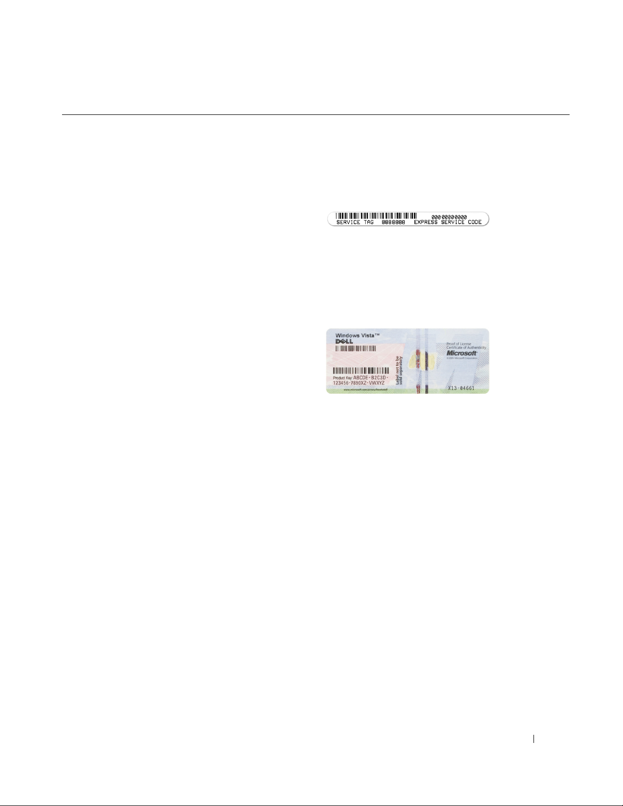
• Service Tag and Express Service Code
• Microsoft Windows License Label
Service Tag and Microsoft® Windows® License
NOTE: Your computer’s Service Tag and Microsoft
®
Windows
Your computer’s Service Tag contains both a Service Tag
number and an Express Service Code.
• Use the Service Tag to identify your computer when you
use
• Enter the Express Service Code to direct your call when
contacting support.
Use the product key on the Microsoft Windows License
Label if you need to reinstall your operating system.
• Use the product key on the License Label if you need to
reinstall your operating system.
License labels are located on your computer.
support.dell.com
or contact support.
®
NOTE: As an increased security measure, the newly
designed Microsoft Windows license label incorporates a
missing portion or "hole" to discourage removal of the label.
Finding Information 15
Page 16

What Are You Looking For? Find It Here
• Solutions — Troubleshooting hints and tips, articles
from technicians, online courses, and frequently asked
questions
• Community — Online discussion with other Dell
customers
• Upgrades — Upgrade information for components, such
as memory, the hard drive, and the operating system
• Customer Care — Contact information, service call and
order status, warranty, and repair information
• Service and support — Service call status and support
history, service contract, online discussions with
technical support
• Dell Technical Update Service — Proactive e-mail
notification of software and hardware updates for your
computer
• Reference — Computer documentation, details on my
computer configuration, product specifications, and
white papers
• Downloads — Certified drivers, patches, and software
updates
• Desktop System Software (DSS)— If you reinstall the
operating system for your computer, you should also
reinstall the DSS utility. DSS provides critical updates
for your operating system and support for Dell™
3.5-inch USB floppy drives, AMD™ processors, optical
drives, and USB devices. DSS is necessary for correct
operation of your Dell computer. The software
automatically detects your computer and operating
system and installs the updates appropriate for your
configuration.
Dell Support Website — support.dell.com
NOTE: Select your region or business segment to view the
appropriate support site.
To download Desktop System Software:
1
Go to
support.dell.com
2
Click
Select Model
3
Select your product model and click
service tag and click
4
Click
System Utilities
5
Click
Desktop System Software
click
Download Now
6
Click
Run
to run the driver, or
and click
.
Go
.
.
.
Drivers and Downloads
Confirm
under
Save
to save the driver to
, or enter a
Dell - Utility
, and
your computer.
NOTE: The support.dell.com user interface may vary
depending on your selections.
NOTE: DSS may or may not be available for your computer
model.
.
COMMENT
• Software upgrades and troubleshooting hints —
Frequently asked questions, hot topics, and general
health of your computing environment
16 Finding Information
Dell Support 3
Dell Support 3 is an automated upgrade and notification
system installed on your computer. This support provides
real-time health scans of your computing environment,
software updates, and relevant self-support information.
Access Dell Support 3 from the
icon in the taskbar.
Page 17

What Are You Looking For? Find It Here
• How to find information about my computer and its
components
• How to connect to the Internet
• How to add user accounts for different people
• How to transfer files and settings from another
computer
COMMENT
• How to use Microsoft Windows XP or Windows Vista
• How to work with programs and files
• How to personalize my desktop
Windows Welcome Center
The Windows Welcome Center automatically appears
when you use the computer for the first time. You can
choose to have it appear every time you start your
computer by placing a check in the Run at startup
checkbox. Another method of accessing the Welcome
Center is to click the Windows Vista Start button , and
then click Welcome Center.
Windows Help and Support
Microsoft Windows XP:
1
Click the
®
2
Either select one of the topics listed, or type a word or
phrase that describes your problem into the
Start
button and click
Help and Support
Search
click the arrow icon, and then click the topic that
describes your problem.
3
Follow the instructions on the screen.
Microsoft Windows Vista:
1
Click the Windows Vista Start button , and then click
Help and Support
2
In
Search Help
.
, type a word or phrase that describes your
problem, and then press <Enter> or click the magnifying
glass.
3
Click the topic that describes your problem.
4
Follow the instructions on the screen.
.
box,
• Remote help with troubleshooting my computer
DellConnect™ Service and Support
Dell associates can diagnose and repair your computer
remotely over a broadband connection. To learn more and
get started with DellConnect, go to support.dell.com and
click Revolutionary remote help—DellConnect.
Finding Information 17
Page 18

What Are You Looking For? Find It Here
• How to reinstall my operating system
Operating System Media
NOTE: The Operating System media may be optional and may
not ship with your computer.
The operating system is already installed on your computer.
To reinstall your operating system, use the Operating
System media. See "Reinstalling Microsoft
Vista® and Windows® XP" on page 307.
After you reinstall your
operating system, use the
optional Drivers and
Utilities media to reinstall
drivers for the devices that
came with your computer.
Your operating system
product key label is located
on your computer.
®
Windows
NOTE: The color of your media varies based on the operating
system you ordered.
18 Finding Information
Page 19

Before You Begin
This chapter provides procedures for removing and installing the components in your computer.
Unless otherwise noted, each procedure assumes that the following conditions exist:
• You have performed the steps in "Turning Off Your Computer" on page 19 and "Before Working
Inside Your Computer" on page 20.
2
• You have read the safety information in your Dell™
• A component can be replaced by performing the removal procedure in reverse order.
Product Information Guide.
Recommended Tools
The procedures in this document may require the following tools:
• Small flat-blade screwdriver
• Phillips screwdriver
• Flash BIOS update program floppy disk, CD, USB key
Turning Off Your Computer
NOTICE: To avoid losing data, save and close any open files and exit any open programs before you turn off
your computer.
1
Shut down the operating system:
a
Save and close any open files, and exit any open programs.
b
Click the
c
In the
The computer turns off after the operating system shutdown process finishes.
Start
button, and then click
Shut Down Windows
Shut Down
window, select
.
Shut down
, and then click OK.
2
Ensure that the computer and any attached devices are turned off.
If your computer and attached devices did not automatically turn off when you shut down your
operating system, turn them off now.
NOTICE: To turn off your computer without shutting down the operating system is not recommended,
because you may lose data. If, however, it is necessary to do so, it may be done by pressing down and
holding the power button for 6 seconds.
Before You Begin 19
Page 20

Before Working Inside Your Computer
Use the following safety guidelines to help protect your computer from potential damage and to help
ensure your own personal safety.
CAUTION: Before you begin any of the procedures in this section, follow the safety instructions in the
Information Guide
CAUTION: Handle components and cards with care. Do not touch the components or contacts on a card. Hold a
card by its edges or by its metal mounting bracket. Hold a component such as a processor by its edges, not by its
pins.
NOTICE: Only a certified service technician should perform repairs on your computer. Damage due to servicing
that is not authorized by Dell is not covered by your warranty.
NOTICE: When you disconnect a cable, pull on its connector or on its strain-relief loop, not on the cable itself.
Some cables have a connector with locking tabs; if you are disconnecting this type of cable, press in on the locking
tabs before you disconnect the cable. As you pull connectors apart, keep them evenly aligned to avoid bending any
connector pins. Also, before you connect a cable, ensure that both connectors are correctly oriented and aligned.
NOTICE: To avoid damaging the computer, perform the following steps before you begin working inside the
computer.
1
Turn off your computer.
NOTICE: To disconnect a network cable, first unplug the cable from your computer and then unplug it from the
network wall jack.
2
Disconnect any telephone or telecommunication lines from the computer.
3
Disconnect your computer and all attached devices from their electrical outlets, and then press the
.
Product
power button to ground the system board.
4
If applicable, remove the computer stand (for instructions, see the documentation that came with the
stand).
CAUTION: To guard against electrical shock, always unplug your computer from the electrical outlet before
removing the cover.
5
Remove the computer cover:
• Remove the mini tower computer cover (see "Removing the Computer Cover" on page 39).
• Remove the desktop computer cover (see "Removing the Computer Cover" on page 177).
• Remove the small form factor computer cover (see "Removing the Computer Cover" on
page 203).
NOTICE: Before touching anything inside your computer, ground yourself by touching an unpainted metal surface,
such as the metal at the back of the computer. While you work, periodically touch an unpainted metal surface to
dissipate any static electricity that could harm internal components.
20 Before You Begin
Page 21
Mini Tower Computer
About Your Mini Tower Computer
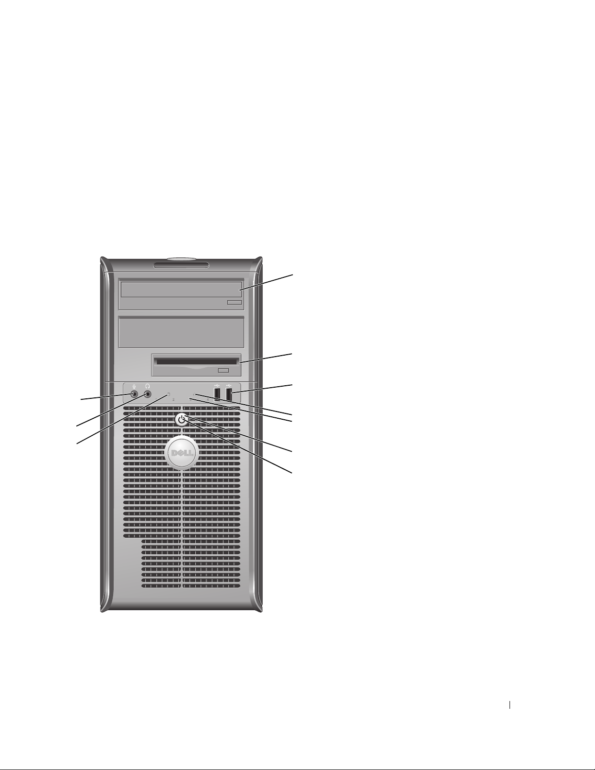
Front View
3
1
2
3
10
4
9
8
5
6
7
Mini Tower Computer 21
Page 22

1 optical drive (optional) Insert media (if supported) into this drive.
2 Flexbay drive Can contain an optional floppy drive or an optional media card reader.
3 USB 2.0 connectors (2) Use the front USB connectors for devices that you connect occasionally, such as
joysticks or cameras, or for bootable USB devices (see "System Setup" on page 257 for
more information on booting to a USB device).
It is recommended that you use the back USB connectors for devices that typically
remain connected, such as printers and keyboards.
4 LAN indicator light This light indicates that a local area network (LAN) connection is established.
5 diagnostic lights Use the lights to help you troubleshoot a computer problem based on the diagnostic
code. For more information, see "Diagnostic Lights" on page 330.
6 power button Press this button to turn on the computer.
NOTICE: To avoid losing data, do not turn off the computer by pressing the power
button. Instead, perform an operating system shutdown. See "Turning Off Your
Computer" on page 19 for more information.
NOTICE: If your operating system has ACPI enabled, when you press the power
button the computer will perform an operating system shutdown.
7 power light The power light illuminates and blinks or remains solid to indicate different operating
modes:
• No light — The computer is turned off.
• Steady green — The computer is in a normal operating state.
• Blinking green — The computer is in a power-saving mode.
• Blinking or solid amber — See "Power Problems" on page 321.
To exit from a power-saving mode, press the power button or use the keyboard or the
mouse if it is configured as a wake device in the Windows Device Manager. For more
information about sleep modes and exiting from a power-saving mode, see "Power
Management" on page 267.
See "System Lights" on page 329 for a description of light codes that can help you
troubleshoot problems with your computer.
8 hard-drive activity light This light flickers when the hard drive is being accessed.
9 headphone connector Use the headphone connector to attach headphones and most kinds of speakers.
10 microphone connector Use the microphone connector to attach a microphone.
22 Mini Tower Computer
Page 23

Back View
1
2
3
4
5
6
Mini Tower Computer 23
Page 24

1 cover release latch This latch allows you to open the computer cover.
2 padlock ring Insert a padlock to lock the computer cover.
3 voltage selection switch Your computer is equipped with a manual voltage-selection switch.
To help avoid damaging a computer with a manual voltage selection switch, set the
switch for the voltage that most closely matches the AC power available in your
location.
NOTICE: In Japan, the voltage selection switch must be set to the 115-V position
.
even though the AC power available in Japan is 100 V.
Also, ensure that your monitor and attached devices are electrically rated to operate
with the AC power available in your location.
4 power connector Insert the power cable.
5 back-panel connectors Plug serial, USB, and other devices into the appropriate connectors. See "Back-Panel
Connectors" on page 25.
6 card slots Access connectors for any installed PCI and PCI Express cards.
24 Mini Tower Computer
Page 25
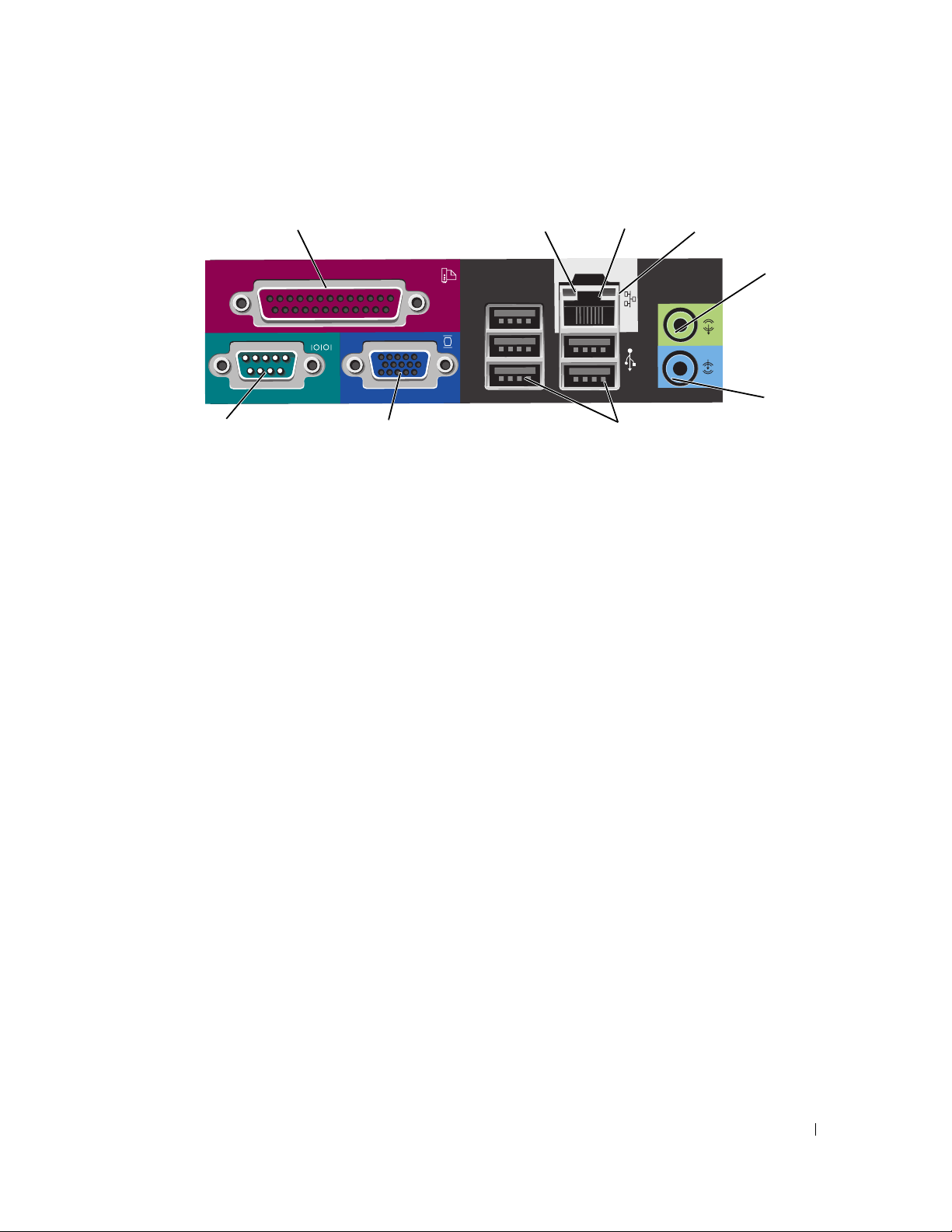
Back-Panel Connectors
1
9
1 parallel connector Connect a parallel device, such as a printer, to the parallel connector. If you have a
USB printer, plug it into a USB connector.
8
2
3
7
4
5
6
NOTE: The integrated parallel connector is automatically disabled if the computer
detects an installed card containing a parallel connector configured to the same
address. For more information, see "System Setup Options" on page 258.
2 link integrity light
3 network adapter
connector
• Green — A good connection exists between a 10-Mbps network and the
computer.
• Orange — A good connection exists between a 100-Mbps network and the
computer.
• Yellow — A good connection exists between a 1-Gbps (or 1000-Mbps) network
and the computer.
• Off — The computer is not detecting a physical connection to the network.
To attach your computer to a network or broadband device, connect one end of a
network cable to either a network jack or your network or broadband device.
Connect the other end of the network cable to the network adapter connector on
the back panel of your computer. A click indicates that the network cable has been
securely attached.
NOTE: Do not plug a telephone cable into the network connector.
On computers with a network connector card, use the connector on the card.
It is recommended that you use Category 5 wiring and connectors for your
network. If you must use Category 3 wiring, force the network speed to 10 Mbps to
ensure reliable operation.
4 network activity light Flashes a yellow light when the computer is transmitting or receiving network
data. A high volume of network traffic may make this light appear to be in a steady
"on" state.
5 line-out connector Use the green line-out connector to attach headphones and most speakers with
integrated amplifiers.
On computers with a sound card, use the connector on the card.
Mini Tower Computer 25
Page 26

6 line-in connector Use the line-in connector to attach a record/playback device such as a cassette
player, CD player, or VCR.
On computers with a sound card, use the connector on the card.
7 USB 2.0 connectors (5) Use the back USB connectors for devices that typically remain connected, such as
printers and keyboards.
8 video connector Plug the cable from your VGA-compatible monitor into the blue connector.
NOTE: If you purchased an optional graphics card, this connector will be covered by
a cap. Do not remove the cap. Connect your monitor to the connector on the graphics
card.
NOTE: If you are using a graphics card that supports dual monitors, use the y-cable
that came with your computer.
9 serial connector Connect a serial device, such as a handheld device, to the serial port. The default
designations are COM1 for serial connector 1 and COM2 for serial connector 2.
For more information, see "System Setup Options" on page 258.
Inside Your Computer
CAUTION: Before you begin any of the procedures in this section, follow the safety instructions located in the
Product Information Guide
CAUTION: To avoid electrical shock, always unplug your computer from the electrical outlet before removing
the computer cover.
.
NOTICE: Be careful when opening the computer cover to ensure that you do not accidentally disconnect cables
from the system board.
26 Mini Tower Computer
Page 27
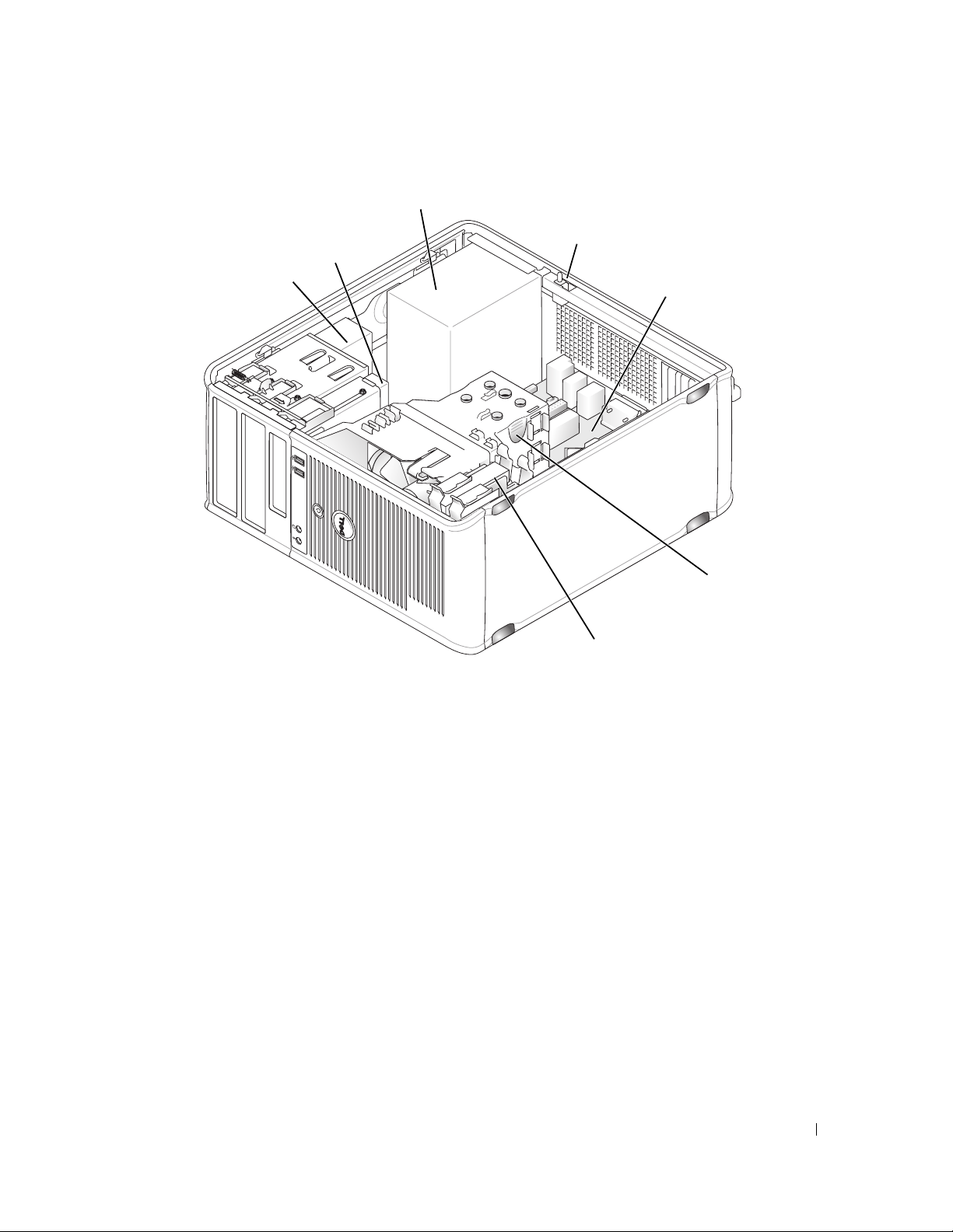
3
4
2
1
7
5
6
1 optical drive 2 floppy drive 3 power supply
4 chassis intrusion switch
(optional)
7 hard drive
5 system board 6 heat sink assembly
Mini Tower Computer 27
Page 28
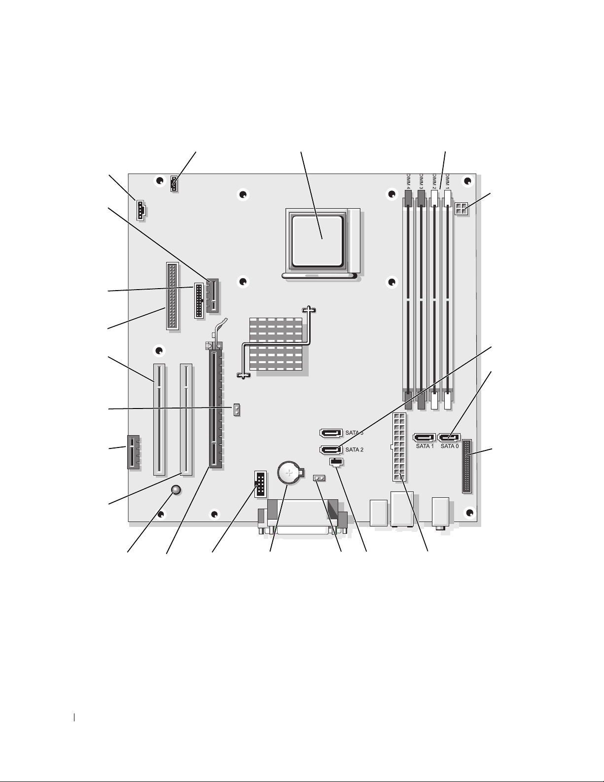
System Board Components
21
20
19
18
17
22
1
2
3
4
5
6
16
15
14
13
28 Mini Tower Computer
12
11
10
7
9
8
Page 29

1 speaker connector
(INT_SPKR)
4 power connector
(PW_12V_A1)
7 front-panel connector
(FRONTPANEL)
10 CMOS reset jumper
(RTCRST)
13 PCI Express x16 connector
(SLOT1)
16 PCI Express x1 connector
(SLOT4)
19 floppy drive connector
(DSKT)
22 fan connector (FAN_CPU)
2 processor socket (CPU) 3 memory module connectors
(DIMM_1, DIMM_2,
DIMM_3, DIMM_4)
5 SATA drive connectors
(SATA2, SATA3)
8 power connector (POWER1) 9 intrusion switch connector
11 battery socket (BATTERY) 12 internal USB (USB1)
14 standby power
(AUX_PWR_LED)
17 password jumper (PSWD) 18 PCI connector (SLOT3)
20 serial connector (PS2/SER2) 21 Optional DVI-card connector
6 SATA drive connectors
(SATA0, SATA1)
(INTRUDER)
15 PCI connector (SLOT2)
(DVI_HDR)
Mini Tower Computer 29
Page 30

30 Mini Tower Computer
Page 31

Mini Tower Computer (Model #DCSM) Specifications
.
Microprocessor
Microprocessor type AMD Phenom™ processors
NOTE: The AMD Phenom processor requires the 8-Mb NVRAM chip
and is therefore available only on models that include the 8-Mb
NVRAM chip. If your computer has the 8-Mb NVRAM chip and the
AMD Phenom processor, the word enhanced appears in the title on
the BIOS splash screen and the system setup program screens.
AMD Athlon™ 64 X2 Dual-Core processor
AMD Athlon 64
Internal cache AMD Phenom Quad-Core: 2-MB L2 dedicated cache and 2-MB
shared L3 cache
AMD Phenom Triple-Core: 1.5-MB L2 dedicated cache and 2-MB
shared L3 cache
AMD Athlon 64 X2: 2-MB L2 dedicated cache
AMD Athlon 64 X2:1-MB L2 dedicated cache
AMD Athlon: 1-MB L2 dedicated cache
AMD Athlon: 512-KB L2 dedicated cache
Memory
Type 533-, 667-, or 800-MHz DDR2 SDRAM
Memory connectors 4
Memory modules supported 256 MB, 512 MB, 1 GB, or 2 GB non-ECC
Minimum memory dual-channel: 512 MB
single-channel: 256 MB
Maximum memory 8 GB
Computer Information
Chipset nVidia GeForce 6150LE/Nforce 430
RAID support RAID 0 and RAID 1
NOTE: RAID support is available only for select models.
Data bus width 64 bits
Mini Tower Computer 31
Page 32

Computer Information
Address bus width 40 bits
DMA channels eight
Interrupt levels 24
BIOS chip (NVRAM) 8 Mb or 4 Mb
NOTE: The AMD Phenom processor requires the 8-Mb NVRAM chip
and is therefore available only on models that include the 8-Mb
NVRAM chip. If your computer has the 8-Mb NVRAM chip and the
AMD Phenom processor, the word enhanced appears in the title on
the BIOS splash screen and the system setup program screens.
NIC support for Atmel 1-Mb and 2-Mb EEPROM
Capable of 10/100/1000 communication
Video
Type nVidia integrated video (DirectX 9.0c Shader Model 3.0 Graphics
Processing Unit) or PCI Express x16 graphics card or DVI graphics
card
Audio
Type Sigma Tel 9200 CODEC (2.1 Channel Audio)
Stereo conversion 24-bit analog-to-digital; 24-bit digital-to-analog
Controllers
Drives two SATA controllers supporting two devices each, including two
3.5-inch hard drives
Expansion Bus
Bus type PCI 2.3
PCI Express 1.0A
SATA 1.0A and 2.0
USB 2.0
Mini Tower Computer 32
Page 33

Expansion Bus
Bus speed PCI: 133 MB/s
PCI Express x16: 40 GB/s bidirectional speed
PCI Express x1: 2.5 Gbps
SATA: 1.5 Gbps and 3.0 Gbps
USB: 480-Mbps high speed, 12-Mbps full speed, 1.2-Mbps low
speed
Cards: full-height cards supported
PCI:
connectors
connector size
connector data width
(maximum)
PCI Express:
connectors
power
connector size
connector data width
(maximum)
Drives
Externally accessible two 3.5-inch drive bays, including support for up to two 3.5-inch
Internally accessible two bays for 1-inch-high hard drives
Connectors
External connectors:
two
124 pins
32 bits
one x1 and one x16
10 W (x1) and 75 W (x16) maximum
36 pins (x1) and 164 pins (x16)
one PCI Express lane (x1) and 16 PCI Express lanes (x16)
hard drives
two 5.25-inch drive bays
Serial
Parallel
Video
Optional DVI
9-pin connector; 16550C-compatible
25-hole connector (bidirectional)
15-hole VGA connector
36-pin connector
NOTE: This option uses one of the PCI slots.
Mini Tower Computer 33
Page 34

Connectors
Network adapter
Optional PS/2 with secondary serial
port adapter
USB
Audio
System board connectors:
SATA
Floppy drive
Serial
Fan
PCI 2.3
PCIe-x1
PCIe-x16
Internal USB
Intrusion switch
RJ45 connector
two 6-pin mini-DINs
NOTE: This option uses one of the PCI slots.
two front-panel and five back-panel USB 2.0–compliant
connectors
two connectors for line-in and line-out; two front-panel connectors
for headphones and microphone
four 7-pin connectors
34-pin connector
24-pin connector for optional second serial port card
5-pin connector
two 124-pin connectors
36-pin connector
164-pin connector
10-pin connector
3-pin connector
Speaker
Memory modules
Power 12V
Power
Battery
Front panel
Key Combinations
<Ctrl><Alt><Del> in Microsoft
<F2> or <Ctrl><Alt><Enter> starts embedded system setup (during start-up only)
5-pin connector
four 240-pin connector
4-pin connector
24-pin connector
2-pin socket
40-pin connector
®
Windows® XP and Windows Vista®, brings up the
Windows Security window. If in MS-DOS
(reboots) the computer.
®
mode, restarts
Mini Tower Computer 34
Page 35

Key Combinations
<F12> or <Ctrl><Alt><F8> displays a boot device menu that allows the user to enter a device
for a single boot (during start-up only) as well as options to run
hard-drive and system diagnostics
<Ctrl><n> starts the RAID setup menu if RAID is turned on in the system
setup program
<Ctrl><Enter> disables computer password at start-up (after correct password is
entered)
Controls and Lights
Power control front of chassis - push button
Power light (within the power
button)
Hard-drive access light front panel - green
Link light (on front panel) front panel - solid green light indicates network connection
Link integrity light (on integrated
network adapter)
Activity light (on integrated network
adapter)
Diagnostic lights front panel - four lights on the front panel. See "Diagnostic Lights"
Standby power light AUX_PWR on the system board
Power
DC power supply:
Wattage
Heat dissipation
green light — Blinking green indicates sleep mode; solid green
indicates power-on state.
amber light — Blinking amber indicates a problem with an
installed device; solid amber indicates an internal power problem
(see "Power Problems" on page 321).
rear panel - green light for 10-Mb operation; orange light for 100Mb operation; yellow light for a 1000-Mb (1-Gb) operation
rear panel - yellow blinking light
on page 330.
305 W
1040.7 BTU/hr maximum
Vo lt a ge
Backup battery 3-V CR2032 lithium coin cell
manual selection power supplies—90 to 135 V at 50/60 Hz; 180 to
265 V at 50/60 Hz
Mini Tower Computer 35
Page 36

Physical
Height
Width
Depth
We ig h t
Environmental
Temperature:
Operating
Storage
Relative humidity 20% to 80% (noncondensing)
Maximum vibration:
Operating
Storage
Maximum shock:
Operating
Storage
41.4 cm (16.3 inches)
18.5 cm (7.3 inches)
43.9 cm (17.3 inches)
12.34 kg (27.2 lb)
10° to 35°C (50° to 95°F)
–40° to 65°C (–40° to 149°F)
0.25 G at 3 to 200 Hz at 0.5 octave/min
0.5 G at 3 to 200 Hz at 1 octave/min
bottom half-sine pulse with a change in velocity of 50.8 cm/sec (20
inches/sec)
27-G faired square wave with a velocity change of 508 cm/sec (200
inches/sec)
Altitude:
Operating
Storage
Airborne contaminant level G2 or lower as defined by ISA-S71.04-1985
–15.2 to 3048 m (–50 to 10,000 ft)
–15.2 to 10,668 m (–50 to 35,000 ft)
Mini Tower Computer 36
Page 37

I/O Panel
Removing the I/O Panel
CAUTION: Before you begin any of the procedures in this section, follow the safety instructions located in
Product Information Guide
the
CAUTION: To guard against electrical shock, always unplug your computer from the electrical outlet before
removing the cover.
NOTE: Note the routing of all cables as you remove them so that you can re-route them correctly when
installing the new I/O panel.
1
Follow the procedures in "Before You Begin" on page 19.
NOTICE: When sliding the I/O panel out of the computer, be extremely careful. Carelessness may result in
damage to the cable connectors and the cable routing clips.
2
Remove the screw that secures the I/O panel. Press on the release button and slide the card away
from the front of the computer.
3
Carefully remove the panel from the computer.
4
Disconnect all of the cables from the I/O panel.
.
Mini Tower Computer 37
Page 38

1
2
3
4
5
1 I/O panel release button 2 securing screw 3 I/O panel
4 I/O cable connector 5 pull-loop
Replacing the I/O Panel
To replace the I/O panel, follow the removal procedure in the reverse order.
NOTE: Use the guides on the I/O panel bracket to help position the I/O panel in place, and use the notch on
the I/O panel bracket to help seat the panel.
Mini Tower Computer 38
Page 39

Removing the Computer Cover
CAUTION: Before you begin any of the procedures in this section, follow the safety instructions located in
the
Product Information Guide
CAUTION: To guard against electrical shock, always unplug your computer from the electrical outlet before
removing the computer cover.
1
Follow the procedures in "Before You Begin" on page 19.
2
Lay the computer on its side as shown in the illustration.
3
Locate the cover release latch shown in the illustration. Then, slide the release latch back as you
lift the cover.
4
Grip the sides of the computer cover and pivot the cover up using the hinge tabs as leverage
points.
5
Remove the cover from the hinge tabs and set it aside on a soft nonabrasive surface.
CAUTION: Graphic card heat sinks can become very hot during normal operation. Ensure that a graphic
card heat sink has had sufficient time to cool before you touch it.
.
Mini Tower Computer 39
Page 40

1
2
3
1 security cable slot 2 cover release latch 3 padlock ring
40 Mini Tower Computer
Page 41

PCI, PCI Express Cards, and PS/2 Serial Port Adapters
CAUTION: Before you begin any of the procedures in this section, follow the safety instructions located in
the
Product Information Guide
NOTICE: To prevent static damage to components inside your computer, discharge static electricity from
your body before you touch any of your computer’s electronic components. You can do so by touching an
unpainted metal surface on the computer chassis.
Your Dell™ computer supports a PS/2 serial adapter and provides the following connectors for PCI
and PCI Express cards.
•Two PCI card slots
• One PCI Express x16 card slot
• One PCI Express x1 card slot
NOTE: Your Dell computer uses only PCI and PCI Express slots. ISA cards are not supported.
PCI Cards
.
Installing a PCI Card
1
Follow the procedures in "Before You Begin" on page 19.
NOTE: For PCI card locations, see "System Board Components" on page 28.
2
Gently push the release tab on the card retention latch from the inside to pivot the latch open.
The latch will remain in the open position.
MiniTower Computer 41
Page 42

2
1
3
4
6
1 card retention latch 2 alignment guide 3 card
4 card-edge connector 5 card connector 6 release tab
3
If you are installing a new card, remove the filler bracket to create a card-slot opening. Then continue
5
with step 5.
4
If you are replacing a card that is already installed in the computer, remove the card (see "Removing a
PCI Card" on page 44). If necessary, disconnect any cables connected to the card. Then continue with
step 6.
5
Prepare the new card for installation.
CAUTION: Some network adapters automatically start the computer when they are connected to a network. To
guard against electrical shock, be sure to unplug your computer from its electrical outlet before installing any
cards.
NOTE: See the documentation that came with the card for information on configuring the card, making internal
connections, or customizing it for your computer
6
Place the card in the connector and press down firmly. Ensure that the card is fully seated in the slot.
NOTE:
If the card is full-length, insert the end of the card into the card-guide bracket as you lower the
card toward its connector on the system board. Insert the card firmly into the card connector on the
system board
.
42 Mini Tower Computer
Page 43

2
1
1 fully seated card 2 not fully seated card 3 bracket within slot
4 bracket caught outside of slot
7
Secure the card(s) by closing the card retention latch and snapping it into place.
NOTICE: Do not route card cables over the cards. Cables routed over the cards can prevent the computer cover
from closing properly or cause damage to the equipment.
3
4
8
Connect any cables that should be attached to the card.
9
Replace the computer cover (see "Replacing the Computer Cover" on page 297).
NOTICE: To connect a network cable, first plug the cable into the network wall jack and then plug it into the
computer.
NOTE: See the documentation for the card for information about the card’s cable connections.
10
If you installed a sound card:
a
Enter system setup, select
Off
setting to
b
Connect external audio devices to the sound card’s connectors. Do not connect external audio
(see "System Setup" on page 257).
Integrated Audio
from the
Onboard Devices
group, and change the
devices to the line-in connector on the back panel of the computer (see "Back-Panel Connectors"
on page 25).
11
If you installed a network adapter card and want to turn off the integrated network adapter:
a
Enter system setup, select
Off
setting to
(see "System Setup" on page 257).
Integrated NIC
from the
Onboard Devices
group, and change the
Mini Tower Computer 43
Page 44

b
Connect the network cable to the network adapter card’s connectors. Do not connect the network
cable to the integrated network connector on the back panel of the computer.
12
Install any drivers required for the card as described in the card documentation.
Removing a PCI Card
1
Follow the procedures in "Before You Begin" on page 19
2
Gently push the release tab on the card retention latch from the inside to pivot the latch open. The
latch will remain in the open position.
2
1
3
4
6
1 card retention latch 2 alignment guide 3 card
4 card-edge connector 5 card connector 6 release tab
3
If necessary, disconnect any cables connected to the card.
4
Grasp the card by its top corners, and ease it out of its connector.
5
If you are removing the card permanently, install a filler bracket in the empty card-slot opening.
NOTE: Installing filler brackets over empty card-slot openings is necessary to maintain FCC certification of the
computer. The brackets also keep dust and dirt out of your computer.
6
Before you close the card retention mechanism, ensure that:
5
• The tops of all cards and filler brackets are flush with the alignment bar.
44 Mini Tower Computer
Page 45

• The notch in the top of the card or filler bracket fits around the alignment guide.
2
1
1 fully seated card 2 not fully seated card 3 bracket within slot
4 bracket caught outside of slot
7
Secure the card(s) by closing the card retention latch and snapping it into place.
8
Replace the computer cover (see "Replacing the Computer Cover" on page 297).
9
Uninstall the card’s driver. See the documentation that came with the card for instructions.
3
4
10
If you removed a sound card:
a
Enter system setup, select
change the setting to
b
Connect external audio devices to the audio connectors on the back panel of the
Integrated Audio
On
(see "System Setup" on page 257).
computer.
11
If you removed an network-adapter card connector:
a
Enter system setup, select
On
the setting to
b
Connect the network cable to the integrated network connector on the back panel of the
(see "System Setup" on page 257).
Integrated NIC
computer.
from the
from the
Onboard Devices
Onboard Devices
group, and
group, and change
Mini Tower Computer 45
Page 46

PCI Express Cards
Your computer supports one PCI Express x16 card and one PCI Express x1 card. See "System Board
Components" on page 28 for the location of the PCI Express card slots.
1
4
5
1 PCI Express x1 card 2 PCI Express x16 card 3 PCI Express x16 DVI card
4 PCI Express x1 card slot 5 PCI Express x16 card slot 6 PCI Express x16 DVI
2
card slot
3
6
If you are replacing a card, uninstall the driver for the existing card. See the documentation that came
with the card for instructions.
Installing a PCI Express x1 Card
1
Follow the procedures in "Before You Begin" on page 19.
46 Mini Tower Computer
Page 47

2
1
3
4
6
1 card retention latch 2 alignment guide 3 card
4 card-edge connector 5 card connector 6 release tab
2
Gently push the release tab on the card retention latch from the inside to pivot the latch open. The
5
latch will remain in the open position.
3
If you are installing a new card, remove the filler bracket to create a card-slot opening. Then continue
with step 5.
4
If you are replacing a card that is already installed in the computer, remove the card (see "Removing a
PCI Express x1 Card" on page 49).
If necessary, disconnect any cables connected to the card. Then continue with step 6.
5
Prepare the new card for installation.
See the documentation that came with the card for information on configuring the card, making
internal connections, or otherwise customizing it for your computer.
CAUTION: Some network adapters automatically start the computer when they are connected to a network. To
guard against electrical shock, be sure to unplug your computer from its electrical outlet before installing any
cards.
6
Place the card in the connector and press down firmly. Ensure that the card is fully seated in the slot.
Mini Tower Computer 47
Page 48

1
1 PCI Express x1 card 2 PCI Express x1 card
connector
2
2
1
1 fully seated card 2 not fully seated card 3 bracket within slot
4 bracket caught outside of slot
3
48 Mini Tower Computer
4
Page 49

7
Before you close the card retention mechanism, ensure that:
• The tops of all cards and filler brackets are flush with the alignment bar.
• The notch in the top of the card or filler bracket fits around the alignment guide.
8
Close the card retention latch and gently press until it clicks into place.
NOTICE: Do not route card cables over the cards. Cables routed over the cards can prevent the computer cover
from closing properly or cause damage to the equipment.
NOTICE: To connect a network cable, first plug the cable into the network wall jack and then plug it into the
computer.
9
Connect any cables that should be attached to the card.
See the documentation for the card for information about the card’s cable connections.
10
Replace the computer cover (see "Replacing the Computer Cover" on page 297).
11
If you installed a sound card:
a
Enter system setup, select
Off
setting to
b
Connect external audio devices to the sound card’s connectors. Do not connect external audio
(see "System Setup" on page 257.
Integrated Audio
from the
Onboard Devices
group, and change the
devices to the line-in connector on the back panel of the computer. "Back-Panel Connectors" on
page 25.
12
If you installed a network adapter card and want to turn off the integrated network adapter:
a
Enter system setup, select
Off
setting to
b
Connect the network cable to the network adapter card’s connectors. Do not connect the network
(see "System Setup" on page 257.
Integrated NIC
from the
Onboard Devices
group, and change the
cable to the integrated network connector on the back panel of the computer.
13
Install any drivers required for the card as described in the card documentation.
Removing a PCI Express x1 Card
1
Follow the procedures in "Before You Begin" on page 19.
2
Gently push the release tab on the card retention latch from the inside to pivot the latch open. The
latch will remain in the open position.
Mini Tower Computer 49
Page 50

2
1
3
4
6
1 card retention latch 2 alignment guide 3 card
4 card-edge connector 5 card connector 6 release tab
3
If necessary, disconnect any cables connected to the card.
4
Grasp the card by its top corners, and ease it out of its connector.
5
If you are removing the card permanently, install a filler bracket in the empty card-slot opening.
NOTE: Installing filler brackets over empty card-slot openings is necessary to maintain FCC certification of the
computer. The brackets also keep dust and dirt out of your computer.
6
Before you close the card retention mechanism, ensure that:
5
• The tops of all cards and filler brackets are flush with the alignment bar.
• The notch in the top of the card or filler bracket fits around the alignment guide.
7
Secure the card(s) by closing the card retention latch and snapping it into place.
8
Replace the computer cover (see "Replacing the Computer Cover" on page 297).
50 Mini Tower Computer
Page 51

Installing PCI Express x16 Cards and DVI-Cards
1
Follow the procedures in "Before You Begin" on page 19.
2
If you are replacing a PCI Express x16 card, remove the installed card (see
Cards and DVI-Cards
NOTE: See the documentation that came with the card for information on configuring the card, making internal
connections, or customizing it for your computer.
3
Prepare the card for installation.
CAUTION: Some network adapters automatically start the computer when they are connected to a network. To
guard against electrical shock, be sure to unplug your computer from its electrical outlet before installing any
cards.
4
Place the card in the connector and press down firmly. Ensure that the card is fully seated in the slot.
" on page 54
).
1
"Removing PCI Express x16
2
1 PCI Express x16 card 2 PCI Express x16 card
connector
Mini Tower Computer 51
Page 52

1
3
1 PCI Express x16 card 2 DVI-card connector 3 PCI Express x16 card
2
connector
52 Mini Tower Computer
Page 53

2
1
1 fully seated card 2 not fully seated card 3 bracket within slot
4 bracket caught outside of slot
5
Connect any cables that should be attached to the card.
NOTICE: Do not route card cables over the cards. Cables routed over the cards can prevent the computer cover
from closing properly or cause damage to the equipment.
3
4
6
Before you close the card retention mechanism, ensure that:
• The tops of all cards and filler brackets are flush with the alignment bar.
• The notch in the top of the card or filler bracket fits around the alignment guide.
7
Secure the card(s) by closing the card retention latch and snapping it into place.
8
Replace the computer cover (see "Replacing the Computer Cover" on page 297).
9
If you installed a sound card:
a
Enter system setup, select
Off
setting to
b
Connect external audio devices to the sound card’s connectors. Do not connect external audio
(see "System Setup" on page 257).
Integrated Audio
from the
Onboard Devices
group, and change the
devices to the line-in connector on the back panel of the computer (see "Back-Panel Connectors"
on page 99).
NOTICE: To connect a network cable, first plug the cable into the network wall jack and then plug it into the
computer.
Mini Tower Computer 53
Page 54

10
If you installed a network adapter card and want to turn off the integrated network adapter:
a
Enter system setup, select
Off
setting to
b
Connect the network cable to the network adapter card’s connectors. Do not connect the network
(see "System Setup" on page 257).
Integrated NIC
from the
Onboard Devices
group, and change the
cable to the integrated network connector on the back panel of the computer.
11
Install any drivers required for the card as described in the card documentation.
Removing PCI Express x16 Cards and DVI-Cards
1
Follow the procedures in "Before You Begin" on page 19.
2
Gently lift the release tab on the card retention latch from the inside to pivot the latch open. Pivot the
latch until it snaps into the open position.
3
If necessary, disconnect any cables connected to the card.
4
Press the lever with your thumb until you release the securing tab.
If you are removing a PCI Express x16 card, go to step 5.
If you are removing a DVI-card, go to step 6
5
While pressing the lever, pull the card up and out of the card connector.
2
1
1 PCI Express x16 card 2 lever 3 securing slot
4 securing tab 5 PCI Express x16 card
connector
3
4
5
54 Mini Tower Computer
Page 55

6
While pressing the lever, pull the removal pull tab up and remove the card out of the card connector.
2
1
7
1 PCI Express x16 DVI-card 2 removal pull tab 3 DVI-card connector
4 lever 5 securing slot 6 securing tab
7 PCI Express x16 card
connector
3
4
5
6
7
If you are removing the card permanently, install a filler bracket in the empty card-slot opening.
NOTE: Installing filler brackets over empty card-slot openings is necessary to maintain FCC certification of the
computer. The brackets also keep dust and dirt out of your computer.
8
Before you close the card retention mechanism, ensure that:
• The tops of all cards and filler brackets are flush with the alignment bar.
• The notch in the top of the card or filler bracket fits around the alignment guide.
9
Secure any remaining card(s) by closing the card retention latch and snapping it into place.
NOTICE: Do not route card cables over the cards. Cables routed over the cards can prevent the computer cover
from closing properly or cause damage to the equipment.
10
Replace the computer cover (see "Replacing the Computer Cover" on page 297).
11
Uninstall the card’s driver. See the documentation that came with the card for instructions.
12
If you removed a sound card:
a
Enter system setup, select
On
setting to
(see "System Setup" on page 257).
Integrated Audio
from the
Onboard Devices
Mini Tower Computer 55
group, and change the
Page 56

b
Connect external audio devices to the audio connectors on the back panel of the computer.
NOTICE: To connect a network cable, first plug the cable into the network wall jack and then plug it into the
computer.
13
If you removed a network-adapter card connector:
a
Enter system setup, select
On
setting to
b
Connect the network cable to the integrated network connector on the back panel of the
(see "System Setup" on page 257).
Integrated NIC
from the
Onboard Devices
group, and change the
computer.
PS/2 Serial Port Adapters
CAUTION: Before you begin any of the procedures in this section, follow the safety instructions located in the
Product Information Guide
NOTICE: To prevent static damage to components inside your computer, discharge static electricity from your
body before you touch any of your computer's electronic components. You can do so by touching an unpainted
metal surface on the computer chassis.
Installing a PS/2 Serial Port Adapter
1
Follow the procedures in "Before You Begin" on page 19.
2
Gently push the release tab on the card retention latch from the inside to pivot the latch open. The
latch will remain in the open position.
.
56 Mini Tower Computer
Page 57

2
1
1 card retention latch 2 alignment guide
3
Remove the filler bracket (if applicable).
NOTE: See the documentation that came with the PS/2 serial port adapter for information on configuring the
adapter, making internal connections, or customizing it for your computer.
4
Align the PS/2 serial-port adapter bracket in the retention slot and press down firmly. Ensure that the
adapter is fully seated in the slot.
Mini Tower Computer 57
Page 58

2
1
1 fully seated card 2 not fully seated card 3 bracket within slot
4 bracket caught outside of slot
B
efore you close the card retention mechanism, ensure that:
3
4
• The tops of all adapters and filler brackets are flush with the alignment bar.
• The notch in the top of the adapter or filler bracket fits around the alignment guide.
5
Close the card retention latch and gently press until it snaps into place.
NOTICE: Do not route cables over any installed cards. Cables routed over the cards can prevent the computer
cover from closing properly or cause damage to the equipment.
6
Connect the adapter cable to the serial port adapter connector (PS2/SER2) on the system board (see
"System Board Components" on page 28 for connector locations).
NOTE: See the documentation for the PS/2 serial port adapter for information about the cable connections.
7
Replace the computer cover (see "Replacing the Computer Cover" on page 297).
Removing a PS/2 Serial Port Adapter
1
Follow the procedures in "Before You Begin" on page 19.
2
Gently push the release tab on the card retention latch from the inside to pivot the latch open. The
latch will remain in the open position.
58 Mini Tower Computer
Page 59

2
1
1 card retention latch 2 alignment guide
3
Disconnect the PS/2 serial adapter cable from the system board (see "System Board Components" on
page 28).
4
If necessary, disconnect any external cables connected to the adapter.
5
Grasp the PS/2 serial-port adapter bracket by its top corners, and ease it out of its retention slot.
6
If you are removing the adapter permanently, install a filler bracket in the empty card-slot opening.
NOTE: Installing filler brackets over empty card-slot openings is necessary to maintain FCC certification of the
computer. The brackets also keep dust and dirt out of your computer.
7
Before you close the card retention mechanism, ensure that:
• The tops of all cards and filler brackets are flush with the alignment bar.
• The notch in the top of the card or filler bracket fits around the alignment guide.
8
Secure the card(s) by closing the card retention latch and snapping it into place.
9
Replace the computer cover (see "Replacing the Computer Cover" on page 297).
Mini Tower Computer 59
Page 60

60 Mini Tower Computer
Page 61

Drives
Your computer supports:
• Two SATA (Serial ATA) hard drives
• One optional floppy drive or Media Card Reader
•Two optical drives
2
1
3
1 optical drive 2 floppy drive or media card
reader
3 hard drive
General Installation Guidelines
NOTE: Connect the first SATA hard drive to the blue SATA0 connector.
Connect SATA hard drives to the connectors labeled "SATA0" or "SATA1." Connect SATA CD or
DVD drives to the connectors labeled "SATA2" or "SATA3" on the system board (see "System Board
Components" on page 28 for information about mini tower system board connectors).
Mini Tower Computer 61
Page 62

Connecting Drive Cables
When you install a drive, you connect two cables—a DC power cable and a data cable—to the back of
the drive and to the system board.
Drive Interface Connectors
Serial ATA Connector
1
2
1 interface cable connector 2 interface connector
Interface connectors are keyed for correct insertion.
Power Cable Connectors
Serial ATA Power Connector
1
2
1 power cable 2 power input connector
62 Mini Tower Computer
Page 63

Connecting and Disconnecting Drive Cables
When connecting and disconnecting a SATA data cable, hold the cable by the black connector at each
end.
Hard Drive
CAUTION: Before you begin any of the procedures in this section, follow the safety instructions in the
Information Guide
CAUTION: To guard against electrical shock, always unplug your computer from the electrical outlet before
removing the computer cover.
NOTICE: To avoid damage to the drive, do not set it on a hard surface. Instead, set the drive on a surface, such as
a foam pad, that will sufficiently cushion it.
Removing a Hard Drive
1
If you are replacing a hard drive that contains data you want to keep, back up your files before you
.
begin this procedure.
2
Follow the procedures in "Before You Begin" on page 19.
3
Disconnect the power and hard-drive cables from the drive.
Product
Mini Tower Computer 63
Page 64

1
2
3
1 hard-drive cable 2 hard-drive cable on system
board
4
Press in on the blue release tabs on each side of the drive and slide the drive up and out of the
computer.
64 Mini Tower Computer
3power cable
Page 65

1
1 hard drive 2 release tabs (2)
Installing a Hard Drive
1
Unpack the replacement hard drive, and prepare it for installation.
2
Follow the procedures in "Before You Begin" on page 19.
3
If your replacement hard drive does not have the plastic hard-drive bracket attached:
a
Remove the bracket from the existing drive by gently spreading the plastic hard-bracket and
removing the hard drive.
b
Install the replacement drive into the bracket by inserting the drive into the bracket so that the
bracket alignment tabs snaps into the mounting holes on the new drive.
2
Mini Tower Computer 65
Page 66

1 hard drive 2 hard-drive bracket
1
2
1
2
4
1 hard drive 2 hard drive mounting holes 3 hard-drive bracket
4 bracket alignment tabs
4
Carefully slide the hard drive into the drive bay until it clicks into place.
66 Mini Tower Computer
3
Page 67

5
Connect the power and hard-drive cables to the drive.
6
Check all connectors to be certain that they are properly cabled and firmly seated.
7
Replace the computer cover (see "Replacing the Computer Cover" on page 297).
8
If the drive you just installed is the primary drive, insert a bootable medium into your boot drive. See
the documentation that came with the drive for instructions on installing any software required for
drive operation.
9
Enter system setup and update the appropriate
Setup" on page 257).
10
Exit system setup, and reboot the computer.
11
Partition and logically format your drive before you proceed to the next step.
See the documentation for your operating system for instructions.
12
Test the hard drive by running the Dell Diagnostics (see "Dell Diagnostics" on page 327).
13
If the drive you just installed is the primary drive, install your operating system on the hard drive.
Primary Drive
option (0 or 1) (see "Entering System
Mini Tower Computer 67
Page 68

Adding a Second Hard Drive
CAUTION: Before you begin any of the procedures in this section, follow the safety instructions in the
Information Guide
CAUTION: To guard against electrical shock, always unplug your computer from the electrical outlet before
removing the computer cover.
NOTICE: To avoid damage to the drive, do not set it on a hard surface. Instead, set the drive on a surface, such as
a foam pad, that will sufficiently cushion it.
NOTICE: If you are replacing a hard drive that contains data you want to keep, back up your files before you begin
this procedure.
1
Check the documentation for the drive to verify that it is configured for your computer.
2
Follow the procedures in "Before You Begin" on page 19.
3
Remove the plastic hard-drive bracket from the inside of the hard-drive bay by squeezing the release
.
tabs and gently pulling the bracket up and out of the bay.
4
Install the new drive into the bracket by inserting the drive into the bracket so that the bracket
alignment tabs snaps into the mounting holes on the new drive.
1
2
Product
4
1 hard drive 2 hard drive mounting holes 3 hard-drive bracket
4 bracket alignment tabs
5
If necessary, disconnect the power and SATA cables from the hard drive that is currently installed.
6
Carefully slide the new hard drive into the unused bay until it clicks into place.
68 Mini Tower Computer
3
Page 69

7
Connect the power and SATA cables to the drives.
8
Locate and connect a SATA cable to the SATA1 connector on the system board (see "System Board
Components" on page 28 for mini tower computers).
Mini Tower Computer 69
Page 70

1
2
3
1 hard-drive data cable 2 hard-drivedata cable on
system board
9
Replace the computer cover (see "Replacing the Computer Cover" on page 297).
3 hard-drive power cable
Drive-Panel Inserts
If you are installing a new floppy drive, media card reader, or optical drive instead of replacing a drive,
remove the drive-panel inserts.
1
Follow the procedures in "Before You Begin" on page 19.
2
Remove the drive panel by sliding the drive release latch in the direction indicated on the latch to open
the panel. Then remove it from the hinges.
70 Mini Tower Computer
Page 71

2
1
3
1drive panel 2 release tab 3 drive-panel insert
3
Select the drive-panel insert in front of the drive bay that you want to use.
4
Gently press the release tab of the insert to remove it from the drive panel.
Mini Tower Computer 71
Page 72

1
2
3
1 optical-drive panel insert 2 floppy-drive/media card
reader panel insert
5
Reattach the drive panel to the front of the computer.
The drive panel only fits one way.
3 holder for shoulder screws
72 Mini Tower Computer
Page 73

Floppy Drive
CAUTION: Before you begin any of the procedures in this section, follow the safety instructions located in the
Product Information Guide
CAUTION: To guard against electrical shock, always unplug your computer from the electrical outlet before
removing the computer cover.
Removing the Floppy Drive
1
Follow the procedures in "Before You Begin" on page 19.
2
Remove the drive panel by sliding the drive release latch in the direction indicated on the latch to open
the panel. Then remove it from the hinges.
3
Disconnect the power and floppy-drive cables from the back of the floppy drive.
4
Slide the drive release latch in the direction indicated on the latch until the floppy drive is released;
while holding the latch open, slide the drive out of the computer.
.
Mini Tower Computer 73
Page 74

2
1
1 floppy drive 2 drive release latch
Installing the Floppy Drive
1
If you are replacing a floppy drive, remove the shoulder screws from the existing drive and attach the
screws to the replacement drive.
2
If you are installing a new floppy drive, remove the drive-panel insert (see "Drive-Panel Inserts" on
page 70) for your new drive, remove the shoulder screws from the inside of the drive-panel insert and
attach the screws to the new drive.
74 Mini Tower Computer
Page 75

3
Align the shoulder screws on the floppy drive with the shoulder screw slots, and gently slide the drive
into the bay until it clicks into place.
3
2
1
1 floppy drive 2 shoulder screws (4) 3 shoulder screw slots (2)
4
Attach the power and floppy-drive data cables to the floppy drive.
5
Connect the flopp- drive data cable to the DSKT connector on the system board (see "System Board
Components" on page 28 for the connector location).
6
Install the drive panel to the front of the computer. The drive panel only fits one way (see "Drive-Panel
Inserts" on page 70).
Mini Tower Computer 75
Page 76

1
2
3
1 power cable 2 floppy-drive data cable 3 floppy-drive connector on
system board (DSKT)
7
Replace the computer cover (see "Replacing the Computer Cover" on page 297).
8
Enter system setup and use the
Diskette Drive
option to enable your new floppy drive (see "Entering
System Setup" on page 257).
9
Verify that your computer works correctly by running the Dell Diagnostics (see "Dell Diagnostics" on
page 327).
Media Card Reader
CAUTION: Before you begin any of the procedures in this section, follow the safety instructions located in the
Product Information Guide
CAUTION: To guard against electrical shock, always unplug your computer from the electrical outlet before
removing the computer cover.
Removing the Media Card Reader
1
Follow the procedures in "Before You Begin" on page 19.
76 Mini Tower Computer
.
Page 77

2
Remove the drive panel by sliding the drive release latch in the direction indicated on the latch to open
the panel. Then remove it from the hinges.
3
Disconnect the media card reader cable from the back of the media card reader.
4
Slide the drive release latch in the direction indicated on the latch until the media card reader is
released; while holding the latch open, slide the device out of the computer.
3
2
1
1 media card reader 2 media card reader cable 3 drive release latch
Installing the Media Card Reader
1
If you are replacing a media card reader, remove the shoulder screws from the existing device and
attach the screws to the replacement device.
2
If you are installing a new media card reader, remove the drive-panel insert (see "Drive-Panel Inserts"
on page 70) for your new device, remove the shoulder screws from the inside of the drive-panel insert
and attach the screws to the new device.
3
Align the shoulder screws on the media card reader with the shoulder screw slots, and gently slide the
device into the bay until it clicks into place.
4
Attach the media card reader cable to the media card reader.
Mini Tower Computer 77
Page 78

5
Connect the media card reader cable to the USB1 connector on the system board (see "System Board
Components" on page 28 for the connector location).
4
3
2
1
1 media card reader 2 shoulder screws (4) 3 shoulder screw slots (2)
4 media card reader cable
6
Install the drive panel to the front of the computer. The drive panel only fits one way (see "Drive-Panel
Inserts" on page 70).
7
Replace the computer cover (see "Replacing the Computer Cover" on page 297).
8
Enter system setup and use the
Diskette Drive
option to enable your new media card reader (see
"Entering System Setup" on page 257).
9
Verify that your computer works correctly by running the Dell Diagnostics (see "Dell Diagnostics" on
page 327).
Optical Drive
CAUTION: Before you begin any of the procedures in this section, follow the safety instructions located in the
Product Information Guide
78 Mini Tower Computer
.
Page 79

CAUTION: To guard against electrical shock, always unplug your computer from the electrical outlet before
replacing the cover.
Removing an Optical Drive
1
Follow the procedures in "Before You Begin" on page 19.
2
Remove the drive panel by sliding the drive release latch in the direction indicated on the latch to open
the panel. Then remove it from the hinges.
3
Disconnect the power and optical drive cables from the back of the drive.
4
Slide the drive release latch in the direction indicated on the latch until the optical drive is released;
while holding the latch open, slide the drive out of the computer.
2
1
1 optical drive 2 drive release latch
Installing an Optical Drive
1
Follow the procedures in "Before You Begin" on page 19.
2
If you are replacing a optical drive, remove the shoulder screws from the existing drive and attach the
screws to the replacement drive.
Mini Tower Computer 79
Page 80

3
If you are installing a new optical drive, remove the drive-panel insert for your new drive (see "DrivePanel Inserts" on page 70), remove the shoulder screws from the inside of the drive-panel insert, and
attach the screws to the new drive.
4
Align the shoulder screws on the optical drive with the shoulder screw slots, and slide the drive into the
bay until it clicks into place.
3
2
1
1 optical drive 2 shoulder screws (3) 3 shoulder screw slots (2)
5
Connect the power and optical drive cables to the drive.
80 Mini Tower Computer
Page 81

6
Connect the drive cable to SATA2 or SATA3 on the system board (see "System Board Components" on
page 28 for mini tower computers).
1
2
3
1 power cable 2 optical drive cable 3 optical drive connector
(SATA)
See the documentation that accompanied the drive and controller card to verify that the configuration
is correct for your computer. Change any settings necessary for correct configuration.
7
Check all cable connections, and fold cables out of the way to provide airflow for the fan and cooling
vents.
8
Install the drive panel to the front of the computer. The drive panel only fits one way (see "Drive-Panel
Inserts" on page 70).
9
Replace the computer cover (see "Replacing the Computer Cover" on page 297).
10
Update your configuration information in system setup (see "System Setup" on page 257) by setting
Drive
the appropriate
11
Verify that your computer works correctly by running the Dell Diagnostics (see "Dell Diagnostics" on
option (0 or 1) under
Drives
.
page 327).
Mini Tower Computer 81
Page 82

82 Mini Tower Computer
Page 83

Processor
CAUTION: Before you begin any of the procedures in this section, follow the safety instructions located in
the
Product Information Guide
NOTICE: To prevent static damage to components inside your computer, discharge static electricity from
your body before you touch any of your computer’s electronic components. You can do so by touching an
unpainted metal surface on the computer chassis.
Removing the Processor
1
Follow the procedures in "Before You Begin" on page 19.
2
Loosen the captive screw on each side of the heat sink assembly.
CAUTION: Despite having a plastic shield, the heat sink assembly may be very hot during normal operation.
Be sure that it has had sufficient time to cool before you touch it.
NOTICE: Before rotating the heat sink assembly upward, twist the assembly side to side to help break the
thermal grease bond between the heat sink and the processor. This is to prevent damage to the processor due
to pulling the processor out of the socket while rotating the heat sink assembly upward.
3
Rotate the heat sink assembly upward, and remove it from the computer.
Lay the heat sink assembly down on its top, with the thermal grease facing upward.
.
Mini Tower Computer 83
Page 84

1
2
1 heat sink assembly 2 captive screw housings (2)
NOTICE: Unless a new heat sink is required for the new processor, reuse the original heat sink assembly
when you replace the processor.
4
Pull the release lever straight up until the processor is released.
Mini Tower Computer 84
Page 85

1
2
3
1 processor 2 release lever 3 socket
NOTICE: Be careful not to bend any of the pins when you remove the processor. Bending the pins can
permanently damage the processor.
5
Remove the processor from the socket.
Leave the release lever extended in the release position so that the socket is ready for the new
processor and go to "Installing the Processor" on page 85.
NOTICE: After removing the processor, be careful not to get any thermal grease on the processor pins.
Thermal grease on the pins can permanently damage the processor.
Installing the Processor
NOTICE: Ground yourself by touching an unpainted metal surface on the back of the computer.
Mini Tower Computer 85
Page 86

NOTICE: When replacing the processor, do not bend any of the pins.
1
Follow the procedures in "Before You Begin" on page 19.
NOTICE: Be careful not to bend any of the pins when you unpack the processor. Bending the pins can
permanently damage the processor.
2
Unpack the new processor, being careful not to bend any of the processor pins.
NOTE: You must position the processor correctly in the socket to avoid permanent damage to the processor and the
computer when you turn on the computer.
3
If the release lever on the socket is not fully extended, move it to that position.
4
Align the pin-1 corners of the processor and socket.
1
1 socket and processor pin-1
indicator
4 processor socket
2
3
4
2processor 3release lever
NOTICE: To avoid damage, ensure that the processor aligns properly with the socket, and do not use
excessive force when you install the processor.
Mini Tower Computer 86
Page 87

5
Set the processor lightly in the socket and ensure that the processor is positioned correctly.
6
While lightly pressing down on the processor, rotate the release lever back toward the system
board until it snaps into place, securing the processor.
7
Clean the thermal grease from the bottom of the heat sink.
NOTICE: Ensure that you apply new thermal grease. New thermal grease is critical for ensuring adequate
thermal bonding, which is a requirement for optimal processor operation.
8
Apply the new thermal grease to the top of the processor.
NOTICE: Ensure that the CPU and audio cables are not routed so that they are pinched when the heat sink
assembly is installed.
9
Install the heat sink assembly:
a
Place the heat sink assembly back onto the heat-sink assembly bracket.
b
Rotate the heat sink assembly down towards the computer base and ensure that the two
captive screws are properly aligned with the holes in the system board.
c
Tighten the two captive screws.
NOTICE: Ensure that the heat sink assembly is correctly seated and secure.
Mini Tower Computer 87
Page 88

1
2
3
1 heat sink assembly 2 heat-sink assembly bracket 3 captive screw housing (2)
10
Replace the computer cover (see "Replacing the Computer Cover" on page 297).
Mini Tower Computer 88
Page 89

Power Supply
Replacing the Power Supply
CAUTION: Before you begin any of the procedures in this section, follow the safety instructions located in
Product Information Guide
the
NOTICE: To prevent static damage to components inside your computer, discharge static electricity from
your body before you touch any of your computer’s electronic components. You can do so by touching an
unpainted metal surface on the computer chassis.
1
Follow the procedures in "Before You Begin" on page 19.
2
Disconnect the DC power cables from the system board and the drives.
Note the routing of the DC power cables underneath the tabs in the computer chassis as you
remove them from the system board and drives. You must route these cables properly when you
replace them to prevent them from being pinched or crimped.
3
Remove the four screws that attach the power supply to the back of the computer chassis.
4
Press the release button located on the floor of the computer chassis.
.
Mini Tower Computer 89
Page 90

1
2
3
4
1 release button 2 power supply 3 screws (4)
4 AC power connector
5
Slide the power supply toward the front of the computer by approximately 1 inch.
6
Lift the power supply up and out of the computer.
7
Slide the replacement power supply into place.
8
Replace the screws that secure the power supply to the back of the computer chassis.
Mini Tower Computer 90
Page 91

NOTICE: Route the DC power cables under the chassis tabs. The cables must be properly routed to prevent
the cables from being damaged.
9
Reconnect the DC power cables to the system board and drives.
10
Replace the computer cover (see "Replacing the Computer Cover" on page 297).
11
Connect the AC power cable to the AC power connector.
DC Power Connectors
Mini Tower Computer 91
Page 92

DC Power Connector P1
13 14 15 16 17 18 19 20 21 22 23 24
123456789101112
Pin
Number
1 +3.3 VDC Orange
2 +3.3 VDC Orange
3GND Black
4 +5 VDC Red
5GND Black
6 +5 VDC Red
7GND Black
8PS_PWRGOODGray
9P5AUX Purple
Signal name 18-
AWG
Wire
10 V_12P0_DIG White
11 V_12P0_DIG White
Mini Tower Computer 92
Page 93

Pin
Number
12 +3.3 VDC Orange
13 +3.3VDC/SE* Orange
14 -12 VDC Blue
15 GND Black
16 PWR_PS_ON Green
17 GND Black
18 GND Black
19 GND Black
20 NC NC
Signal name 18-
AWG
Wire
21 +5 VDC Red
22 +5 VDC Red
23 +5 VDC Red
24 GND Black
Mini Tower Computer 93
Page 94

DC Power Connector P2
3
1
Pin
Number
1GNDBlack
2GNDBlack
3 +12 VADC Yellow
4 +12 VADC Yellow
4
2
Signal
Name
18-AWG
Wire
DC Power Connectors P3, P5, P8, and P9
Pin
Number
1 +3.3 VDC Orange
2GNDBlack
3+5 VDCRed
Signal
name
18-AWG
Wire
Mini Tower Computer 94
Page 95

Pin
Number
4GNDBlack
Signal
name
18-AWG
Wire
5 +12
VBDC
White
DC Power Connector P7
Pin
Number
1+5 VDCRed
2GNDBlack
3GNDBlack
Signal
Name
22-AWG
Wire
4 +12
VADC
Ye ll o w
Mini Tower Computer 95
Page 96

Mini Tower Computer 96
Page 97

Desktop Computer
About Your Desktop Computer
Front View
4
1
89
1 USB 2.0 connectors (2) Use the front USB connectors for devices that you connect occasionally, such as
joysticks or cameras, or for bootable USB devices (see "System Setup" on page 257
for more information about booting to a USB device).
It is recommended that you use the back USB connectors for devices that typically
remain connected, such as printers and keyboards.
2 LAN indicator light This light indicates that a local area network (LAN) connection is established.
3 power button Press this button to turn on the computer.
2
7
3
5
4611 10
NOTICE: To avoid losing data, do not turn off the computer by pressing the
power button. Instead, perform an operating system shutdown. See "Turning Off
Your Computer" on page 19 for more information.
NOTICE: If your operating system has ACPI enabled, when you press the
power button the computer will perform an operating system shutdown.
4 Dell badge This badge can be rotated to match the orientation of your computer. To rotate,
place fingers around the outside of the badge, press firmly, and turn the badge. You
can also rotate the badge using the slot provided near the bottom of the badge.
Desktop Computer 97
Page 98

5 power light The power light illuminates and blinks or remains solid to indicate different
operating states:
• No light — The computer is turned off.
• Steady green — The computer is in a normal operating state.
• Blinking green — The computer is in a power-saving mode.
• Blinking or solid amber — See "Power Problems" on page 321.
To exit from a power-saving mode, press the power button or use the keyboard or
the mouse if it is configured as a wake device in the Windows Device Manager. For
more information about sleep modes and exiting from a power-saving mode, see
"Power Management
See "System Lights" on page 329 for a description of light codes that can help you
troubleshoot problems with your computer.
6 diagnostic lights Use the lights to help you troubleshoot a computer problem based on the
diagnostic code. For more information, see "Diagnostic Lights" on page 330.
7 hard-drive activity light This light flickers when the hard drive is being accessed.
8 headphone connector Use the headphone connector to attach headphones and most kinds of speakers.
9 microphone connector Use the microphone connector to attach a microphone.
10 floppy drive Insert a floppy disk into this drive.
11 optical drive Insert media (if supported) into this drive.
" on page 267.
Back View
1
1 card slots Access connectors for any installed PCI and PCI Express cards.
2 back-panel connectors Plug serial, USB, and other devices into the appropriate connectors (see "Back-
3 power connector Insert the power cable.
2 3 4
5
6
Panel Connectors" on page 99).
98 Desktop Computer
Page 99

4 voltage selection switch Your computer is equipped with a manual voltage-selection switch.
To help avoid damaging a computer with a manual voltage selection switch, set
the switch for the voltage that most closely matches the AC power available in
your location.
NOTICE: In Japan, the voltage selection switch must be set to the 115-V
position even though the AC power available in Japan is 100 V.
Also, ensure that your monitor and attached devices are electrically rated to
operate with the AC power available in your location.
5 padlock ring Insert a padlock to lock the computer cover.
6 cover release latch Allows you to open the computer cover.
Back-Panel Connectors
1
9
1 parallel connector Connect a parallel device, such as a printer, to the parallel connector. If you have a
USB printer, plug it into a USB connector.
8
2
3
7
4
5
6
NOTE: The integrated parallel connector is automatically disabled if the computer
detects an installed card containing a parallel connector configured to the same
address. For more information, see "System Setup Options" on page 258.
2 link integrity light
• Green — A good connection exists between a 10-Mbps network and the
computer.
• Orange — A good connection exists between a 100-Mbps network and the
computer.
• Yellow — A good connection exists between a 1-Gbps (or 1000-Mbps) network
and the computer.
• Off — The computer is not detecting a physical connection to the network.
Desktop Computer 99
Page 100

3 network adapter
connector
To attach your computer to a network or broadband device, connect one end of a
network cable to either a network jack or your network or broadband device.
Connect the other end of the network cable to the network adapter connector on
the back panel of your computer. A click indicates that the network cable has been
securely attached.
NOTE: Do not plug a telephone cable into the network connector.
On computers with a network connector card, use the connector on the card.
It is recommended that you use Category 5 wiring and connectors for your
network. If you must use Category 3 wiring, force the network speed to 10 Mbps to
ensure reliable operation.
4 network activity light Flashes a yellow light when the computer is transmitting or receiving network
data. A high volume of network traffic may make this light appear to be in a steady
"on" state.
5 line-out connector Use the green line-out connector to attach headphones and most speakers with
integrated amplifiers.
On computers with a sound card, use the connector on the card.
6 line-in connector Use the line-in connector to attach a record/playback device such as a cassette
player, CD player, or VCR.
On computers with a sound card, use the connector on the card.
7 USB 2.0 connectors (5) Use the back USB connectors for devices that typically remain connected, such as
printers and keyboards.
8 video connector Plug the cable from your VGA-compatible monitor into the blue connector.
NOTE: If you purchased an optional graphics card, this connector will be covered by
a cap. Do not remove the cap. Connect your monitor to the connector on the graphics
card.
NOTE: If you are using a graphics card that supports dual monitors, use the y-cable
that came with your computer.
9 serial connector Connect a serial device, such as a handheld device, to the serial port. The default
designations are COM1 for serial connector 1 and COM2 for serial connector 2.
NOTE: There is only a serial connector 2 if the optional PS2/serial adapter is used.
For more information, see "System Setup Options" on page 258.
100 Desktop Computer
 Loading...