

Page 1

Dell™ OptiPlex™ 740
Quick Reference Guide
Models DCSM, DCNE, DCCY
www.dell.com | support.dell.com
Page 2

Notes, Notices, and Cautions
NOTE: A NOTE indicates important information that helps you make better use of
your computer.
NOTICE: A NOTICE indicates either potential damage to hardware or loss of data
and tells you how to avoid the problem.
CAUTION: A CAUTION indicates a potential for property damage, personal injury,
or death.
If you purchased a Dell™ n Series computer, any references in this document to
Microsoft
®
Windows® operating systems are not applicable.
____________________
Information in this document is subject to change without notice.
© 2008 Dell Inc. All rights reserved.
Reproduction in any manner whatsoever without the written permission of Dell Inc. is strictly
forbidden.
Trademarks used in this text: Dell, OptiPlex, and the DELL logo are trademarks of Dell Inc.; Microsoft,
Windows, Windows Vista, and the Windows Vista Start Button are registered trademarks of Microsoft
Corporation.
Other trademarks and trade names may be used in this document to refer to either the entities claiming
the marks and names or their products. Dell Inc. disclaims any proprietary interest in trademarks and
trade names other than its own.
Models DCSM, DCNE, DCCY
January 2008 P/N CR008 Rev. A01
Page 3

Contents
Finding Information . . . . . . . . . . . . . . . . . . . . 5
Setting Up Your Computer
System Views
. . . . . . . . . . . . . . . . . . . . . . 14
Mini Tower Computer — Front View
Mini Tower Computer — Back View
. . . . . . . . . . . . . . . . 10
. . . . . . . . 14
. . . . . . . . 17
Mini Tower Computer — Back-Panel Connectors
Desktop Computer — Front View
Desktop Computer — Back View
. . . . . . . . . 21
. . . . . . . . . 23
Desktop Computer — Back-Panel Connectors
Small Form Factor Computer — Front View
Small Form Factor Computer — Back View
Small Form Factor Computer — Back-Panel
Connectors
Removing the Computer Cover
Before You Begin
Mini Tower Computer
Desktop Computer
Small Form Factor Computer
Inside Your Computer
Mini Tower Computer
Desktop Computer
Small Form Factor Computer
. . . . . . . . . . . . . . . . . . . . . 30
. . . . . . . . . . . . . 32
. . . . . . . . . . . . . . . . . . 32
. . . . . . . . . . . . . . . . 34
. . . . . . . . . . . . . . . . . 36
. . . . . . . . . . . . 38
. . . . . . . . . . . . . . . . . . 39
. . . . . . . . . . . . . . . . 39
. . . . . . . . . . . . . . . . . 43
. . . . . . . . . . . . 47
. 19
. . 24
. . . . 26
. . . . 29
Solving Problems
Dell Diagnostics
System Lights
. . . . . . . . . . . . . . . . . . . . 50
. . . . . . . . . . . . . . . . . . 51
. . . . . . . . . . . . . . . . . . . . 54
Contents 3
Page 4

Diagnostic Lights. . . . . . . . . . . . . . . . . . . . . 55
Beep Codes
. . . . . . . . . . . . . . . . . . . . . 59
Resolving Software and Hardware
Incompatibilities
Restoring Your Operating System
. . . . . . . . . . . . . . . . . . 60
. . . . . . . . . . 61
Reinstalling Your Microsoft Windows
Operating System
Using the Drivers and Utilities Media
. . . . . . . . . . . . . . . . . . 63
. . . . . . . . 67
Index . . . . . . . . . . . . . . . . . . . . . . . . . . . . . . . 71
4 Contents
Page 5

Finding Information
NOTE: Some features or media may be optional and may not ship with your
computer. Some features or media may not be available in certain countries.
NOTE: Additional information may ship with your computer.
What Are You Looking For? Find It Here
• A diagnostic program for my computer
• Drivers for my computer
• My computer documentation
• My device documentation
• Desktop System Software (DSS)
Drivers and Utilities Media
NOTE: The Drivers and Utilities media may
be optional and may not ship with your
computer.
Documentation and drivers are already
installed on your computer. You can use
the Drivers and Utilities media to reinstall
drivers (see "Using the Drivers and
Utilities Media" on page 67), to run the
Dell Diagnostics (see "Dell Diagnostics"
on page 51), or to access your
documentation.
Readme files may be included on your
media (CD or DVD) to provide the most
current updates about technical changes
to your computer or advanced technicalreference material for technicians or
experienced users.
NOTE: Drivers and documentation updates
can be found at support.dell.com.
Quick Reference Guide 5
Page 6

What Are You Looking For? Find It Here
• Warranty information
• Terms and Conditions (U.S. only)
• Safety instructions
• Regulatory information
• Ergonomics information
• End User License Agreement
Dell™ Product Information Guide
• How to remove and replace parts
• Specifications
• How to configure system settings
• How to troubleshoot and solve
problems
Dell™ OptiPlex™ User’s Guide
Microsoft Windows Help and Support
Center
1
Click
Start
Dell User and System Guides
Guides
.
2
Click the
computer.
The User’s Guide is also available on the
optional Drivers and Utilities media.
→
Help and Support→
User’s Guide
→
for your
System
6 Quick Reference Guide
Page 7
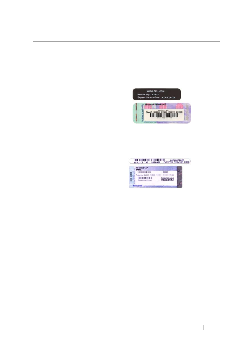
What Are You Looking For? Find It Here
• Service Tag and Express Service Code
• Microsoft Windows License Label
Service Tag and Microsoft® Windows®
License
These labels are located on your
computer.
• Use the Service Tag to identify your
computer when you use
support.dell.com
• Enter the Express Service Code to direct
your call when contacting support.
or contact support.
Quick Reference Guide 7
Page 8
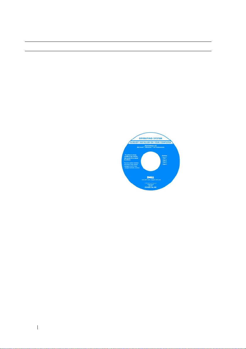
What Are You Looking For? Find It Here
• How to reinstall my operating system
Operating System Media
NOTE: The Operating System media may
be optional and may not ship with your
computer.
The operating system is already installed
on your computer. To reinstall your
operating system, use the Operating
System media. See "Reinstalling Your
Microsoft Windows Operating System"
on page 63.
After you reinstall your operating system,
you can use the optional Drivers and
Utilities media to reinstall drivers for the
devices that came with your computer.
Your operating system product key label is
located on your computer.
NOTE: The color of your media varies
based on the operating system you ordered.
8 Quick Reference Guide
Page 9

What Are You Looking For? Find It Here
• Solutions — Troubleshooting hints and
tips, articles from technicians,
frequently asked questions, and online
courses
Dell Support Website — support.dell.com
NOTE: Select your region or business
segment to view the appropriate support
site.
• Community — Online discussion with
other Dell customers
• Upgrades — Upgrade information for
components, such as memory, the hard
drive, and the operating system
• Customer Care — Contact
information, service call and order
status, warranty, and repair information
• Service and support — Service call
status and support history, service
contract, online discussions with
technical support
• Reference — Computer
documentation, details on my
computer configuration, product
specifications, and white papers
• Downloads — Certified drivers,
patches, and software updates
• Desktop System Software (DSS) — If
you reinstall the operating system for
your computer, you should also reinstall
the DSS utility. DSS provides critical
updates for your operating system and
support for Dell™ 3.5-inch USB floppy
drives, processors, optical drives, and
USB devices. DSS is necessary for
correct operation of your Dell
computer. The software automatically
detects your computer and operating
system and installs the updates
appropriate for your configuration.
To download Desktop System Software:
1
Go to
support.dell.com
region or business segment, and enter
your Service Tag.
2
Select
click
Go
3
Click your operating system and search
for the keyword
Software
NOTE: The support.dell.com user interface
may vary dependent upon your selections.
, select your
Drivers & Downloads
.
Desktop System
.
and
Quick Reference Guide 9
Page 10

What Are You Looking For? Find It Here
• How to use Windows Vista® or
Windows
• How to work with programs and files
• How to personalize my desktop
®
XP
Windows Help and Support Center
1
To access Windows Help and Support:
•
In Windows Vista
Help and Support
In Windows XP
•
and Support
2
Type a word or phrase that describes
your problem and click the arrow icon.
3
Click the topic that describes your
problem.
4
Follow the instructions on the screen.
, click Start →
.
, click
Start
.
Setting Up Your Computer
CAUTION: Before performing any of the procedures in this section, follow the
safety instructions in Product Information Guide.
NOTICE: If your computer has an expansion card installed (such as a modem
card), connect the appropriate cable to the card, not to the connector on the back
panel.
NOTICE: To help allow the computer to maintain proper operating temperature,
ensure that you do not place the computer too close to a wall or other storage
compartment that might prevent air circulation around the chassis.
→ Help
NOTE: Before you install any devices or software that did not ship with your
computer, read the documentation that came with the device or software, or
contact the vendor to verify that the device or software is compatible with your
computer and operating system.
10 Quick Reference Guide
Page 11

You must complete all the steps to properly set up your computer. See the
appropriate figures that follow the instructions.
NOTICE: Do not attempt to operate a PS/2 mouse and a USB mouse
simultaneously.
1
Connect the keyboard and mouse.
NOTICE: Do not connect a telephone line to the network adapter connector.
Voltage from telephone communications can cause damage to the network adapter.
2
Connect the telephone line or network cable.
Insert the network cable, not the telephone line, into the network
connector. If you have an optional modem, connect the telephone line to
the modem.
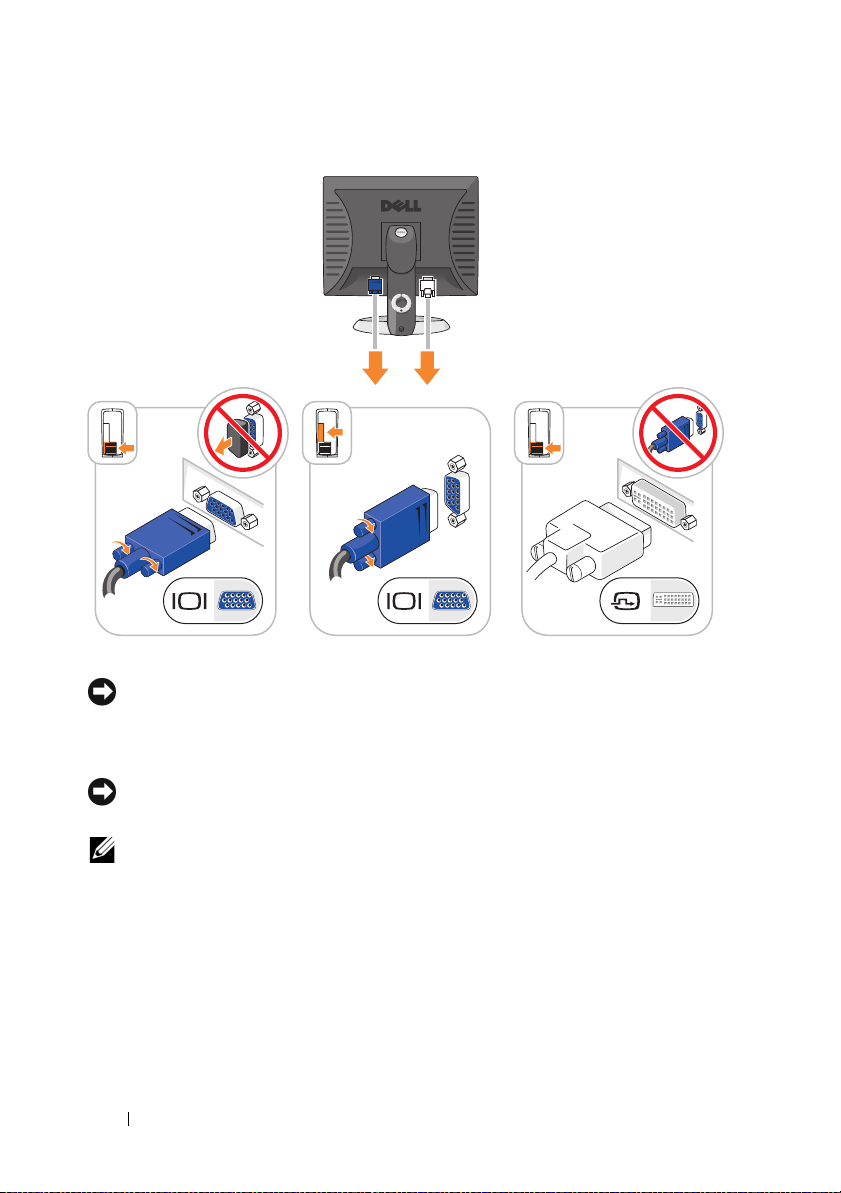
3
Connect the monitor using ONLY ONE of the following cables: the white
DVI cable or the blue VGA cable (do not connect both cables to the same
computer).
Align and gently insert the monitor cable to avoid bending connector pins.
Tighten the thumbscrews on the cable connectors.
NOTE: Some monitors have the video connector underneath the back of the
screen. See the documentation that came with your monitor for its connector
locations.
Quick Reference Guide 11
Page 12
4
Connect the speakers.
NOTICE: To avoid damaging your computer, set the manual voltage-selection
switch (on the back of the computer, if your computer has a voltage selection
switch) for the voltage that most closely matches the AC power available in your
location.
NOTICE: In Japan, the voltage selection switch must be set to the 115-V position
even though the AC power available in Japan is 100 V.
NOTE: Your computer’s power supply may or may not have a voltage selection
switch.
5
Verify that the voltage selection switch is set correctly for your location.
Your computer has a manual voltage-selection switch. Computers with a
voltage selection switch on the back panel must be manually set to operate
at the correct operating voltage.
12 Quick Reference Guide
Page 13

6
Connect power cables to the computer, monitor, and devices and connect
the other ends of the power cables to electrical outlets.
Quick Reference Guide 13
Page 14

System Views
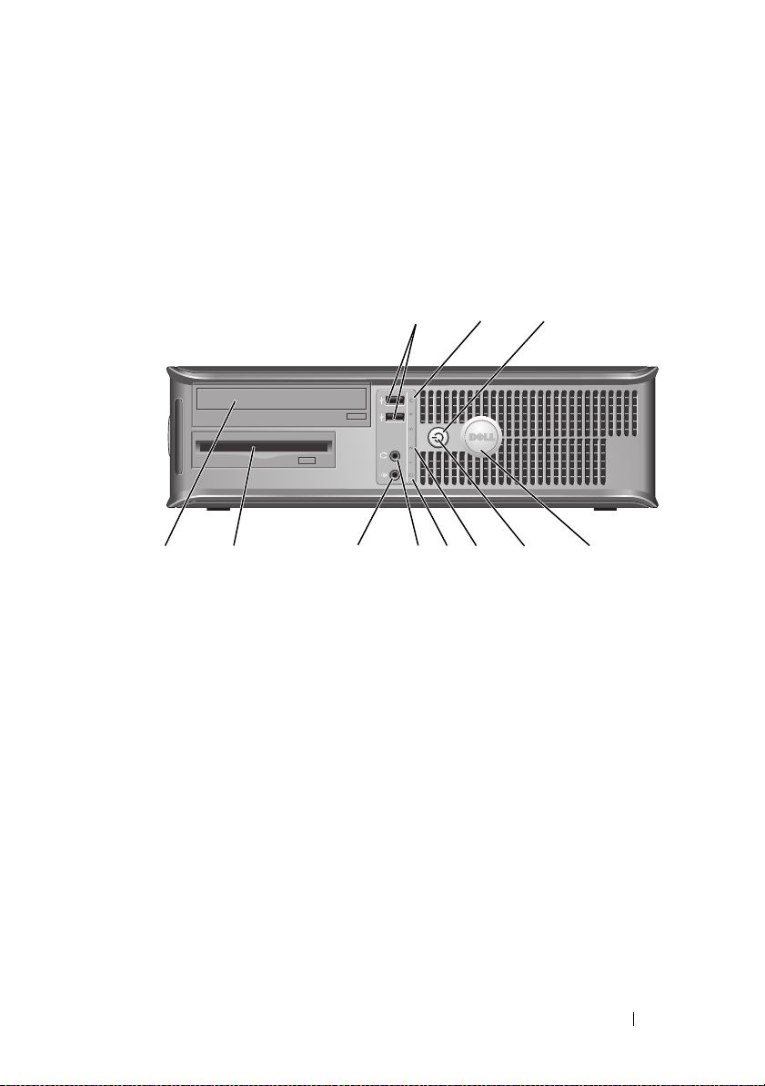
Mini Tower Computer — Front View
10
9
8
1
2
3
4
5
6
7
14 Quick Reference Guide
Page 15

1 optical drive
(optional)
2 floppy drive
bay (optional)
3 USB 2.0
connectors (2)
4 LAN indicator
light
5 diagnostic
lights
6 power button Press this button to turn on the computer.
Insert an optical drive (if supported) into this bay.
Can contain a floppy drive or a optional media card reader.
Use the front USB connectors for devices that you connect
occasionally, such as joysticks or cameras, or for bootable USB
devices (see
more information on booting to a USB device).
It is recommended that you use the back USB connectors for
devices that typically remain connected, such as printers and
keyboards.
This light indicates that a local area network (LAN)
connection is established.
Use the lights to help you troubleshoot a computer problem
based on the diagnostic code. For more information, see
"Diagnostic Lights" on page 55.
"System Setup" in your online User’s Guide for
NOTICE: To avoid losing data, do not turn off the computer
by pressing the power button. Instead, perform an
operating system shutdown. See "Turning Off Your
Computer" in your online User’s Guide for more
information.
NOTICE: If your operating system has ACPI enabled,
when you press the power button the computer will
perform an operating system shutdown.
Quick Reference Guide 15
Page 16

7 power light The power light illuminates and blinks or remains solid to
indicate different operating modes:
• No light — The computer is turned off.
• Steady green — The computer is in a normal operating state.
• Blinking green — The computer is in a power-saving mode.
• Blinking or solid amber — See "Power Problems" in your
online
8 hard-drive
activity light
9 headphone
connector
10 microphone
connector
User’s Guide
To exit from a power-saving mode, press the power button or
use the keyboard or the mouse if it is configured as a wake
device in the Windows Device Manager. For more information
about sleep modes and exiting from a power-saving mode, see
"Power Management" in your online User’s Guide for more
information.
See "System Lights" on page 54 for a description of light codes
that can help you troubleshoot problems with your computer.
This light flickers when the hard drive is being accessed.
Use the headphone connector to attach headphones and most
kinds of speakers.
Use the microphone connector to attach a microphone.
for instructions.
16 Quick Reference Guide
Page 17

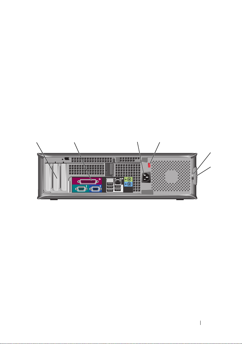
Mini Tower Computer — Back View
1
2
3
4
5
6
1 cover release
latch
2 padlock ring Insert a padlock to lock the computer cover.
This latch allows you to open the computer cover.
Quick Reference Guide 17
Page 18

3 voltage selection
switch
4 power connector Insert the power cable.
5 back-panel
connectors
6 card slots (4) Access connectors for any installed PCI and PCI Express
Your computer may be equipped with a manual voltageselection switch.
To help avoid damaging a computer with a manual voltage
selection switch, set the switch for the voltage that most
closely matches the AC power available in your location.
NOTICE: In Japan, the voltage selection switch must be
set to the 115-V position even though the AC power
available in Japan is 100 V.
Also, ensure that your monitor and attached devices are
electrically rated to operate with the AC power available in
your location.
Plug serial, USB, and other devices into the appropriate
connectors. See "Mini Tower Computer — Back-Panel
Connectors" on page 19.
cards.
18 Quick Reference Guide
Page 19
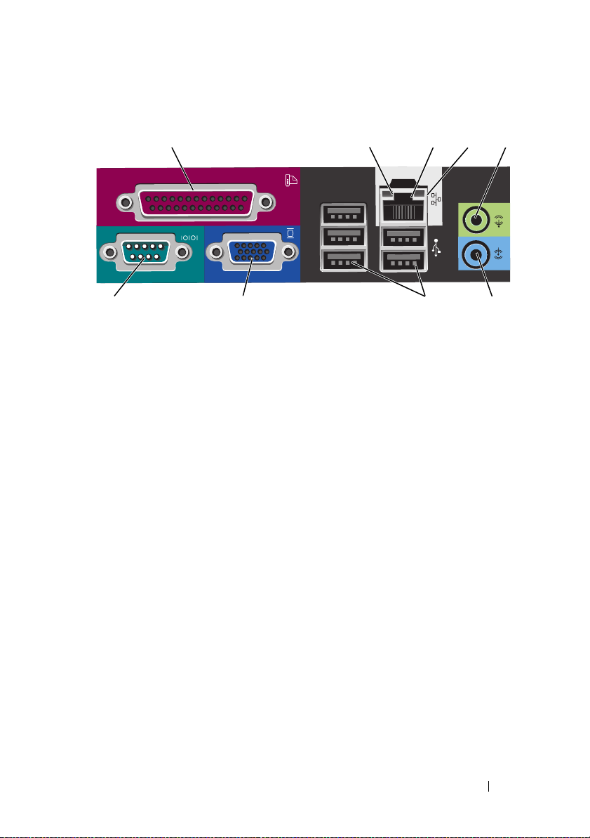
Mini Tower Computer — Back-Panel Connectors
13
98 7
1 parallel connector Connect a parallel device, such as a printer, to the parallel
connector. If you have a USB printer, plug it into a USB
connector.
24
5
6
NOTE: The integrated parallel connector is automatically
disabled if the computer detects an installed card containing a
parallel connector configured to the same address. For more
information, see "System Setup Program" in your online User’s
Guide for instructions.
2 link integrity light
• Green — A good connection exists between a 10-Mbps
network and the computer.
• Orange — A good connection exists between a 100-Mbps
network and the computer.
• Yellow — A good connection exists between a 1-Gbps
(or 1000-Mbps) network and the computer.
• Off — The computer is not detecting a physical
connection to the network.
Quick Reference Guide 19
Page 20

3 network adapter
connector
To attach your computer to a network or broadband device,
connect one end of a network cable to either a network jack
or your network or broadband device. Connect the other
end of the network cable to the network adapter connector
on the back panel of your computer. A click indicates that
the network cable has been securely attached.
NOTE: Do not plug a telephone cable into the network
connector.
On computers with a network connector card, use the
connector on the card.
It is recommended that you use Category 5 wiring and
connectors for your network. If you must use Category 3
wiring, force the network speed to 10 Mbps to ensure
reliable operation.
4 network activity
light
5 line-out
connector
6 line-in connector Use the line-in connector to attach a record/playback device
7 USB 2.0
connectors (5)
8 video connector Plug the cable from your VGA-compatible monitor into the
Flashes a yellow light when the computer is transmitting or
receiving network data. A high volume of network traffic
may make this light appear to be in a steady "on" state.
Use the green line-out connector to attach headphones and
most speakers with integrated amplifiers.
On computers with a sound card, use the connector on the
card.
such as a cassette player, CD player, or VCR.
On computers with a sound card, use the connector on the
card.
Use the back USB connectors for devices that typically
remain connected, such as printers and keyboards.
blue connector.
NOTE: If you purchased an optional graphics card, this
connector will be covered by a cap. Do not remove the cap.
Connect your monitor to the connector on the graphics card.
NOTE: If you are using a graphics card that supports dual
monitors, use the y-cable that came with your computer.
20 Quick Reference Guide
Page 21
9 serial connector Connect a serial device, such as a handheld device, to the
serial port. The default designations are COM1 for serial
connector 1 and COM2 for serial connector 2.
For more information, see "System Setup Program" in your
online User’s Guide.
Desktop Computer — Front View
1 USB 2.0
connectors (2)
1
89
Use the front USB connectors for devices that you connect
occasionally, such as joysticks or cameras, or for bootable
USB devices see "System Setup Program" in your online
User’s Guide for instructions for more information about
booting to a USB device).
It is recommended that you use the back USB connectors
for devices that typically remain connected, such as
printers and keyboards.
2
7
3
5
4611 10
Quick Reference Guide 21
Page 22

2 LAN indicator
light
3 power button Press this button to turn on the computer.
4 Dell badge This badge can be rotated to match the orientation of your
5 power light The power light illuminates and blinks or remains solid to
6 diagnostic lights Use the lights to help you troubleshoot a computer
This light indicates that a local area network (LAN)
connection is established.
NOTICE: To avoid losing data, do not turn off the
computer by pressing the power button. Instead,
perform an operating system shutdown. See "Turning
Off Your Computer" in your online User’s Guide for more
information.
NOTICE: If your operating system has ACPI enabled,
when you press the power button the computer will
perform an operating system shutdown.
computer. To rotate, place fingers around the outside of
the badge, press firmly, and turn the badge. You can also
rotate the badge using the slot provided near the bottom of
the badge.
indicate different operating states:
• No light — The computer is turned off.
• Steady green — The computer is in a normal operating
state.
• Blinking green — The computer is in a power-saving
mode.
• Blinking or solid amber — See "Power Problems" in your
User’s Guide
online
To exit from a power-saving mode, press the power button
or use the keyboard or the mouse if it is configured as a
wake device in the Windows Device Manager. For more
information about sleep modes and exiting from a powersaving mode, see "Power Management" in your online
User’s Guide for instructions.
See "System Lights" on page 54 for a description of light
codes that can help you troubleshoot problems with your
computer.
problem based on the diagnostic code. For more
information, see "Diagnostic Lights" on page 55.
for instructions.
22 Quick Reference Guide
Page 23
7 hard-drive
activity light
8 headphone
connector
9 microphone
connector
10 drive bay This bay accommodates an optional floppy drive, media
11 optical drive
(optional)
This light flickers when the hard drive is being accessed.
Use the headphone connector to attach headphones and
most kinds of speakers.
Use the microphone connector to attach a microphone.
card reader, or second hard drive.
Insert an optical drive (if supported) into this bay.
Desktop Computer — Back View
1 2 3 4
1 card slots (3) Access connectors for any installed PCI and PCI Express
cards.
2 back-panel
connectors
3 power connector Insert the power cable.
Plug serial, USB, and other devices into the appropriate
connectors (see "Desktop Computer — Back-Panel
Connectors" on page 24).
5
6
Quick Reference Guide 23
Page 24

4 voltage selection
switch
5 padlock ring Insert a padlock to lock the computer cover.
6 cover release
latch
NOTE: Your computer may or may not have a voltage selection
switch.
Your computer may equipped with a manual voltageselection switch.
To help avoid damaging a computer with a manual voltage
selection switch, set the switch for the voltage that most
closely matches the AC power available in your location.
NOTICE: In Japan, the voltage selection switch must be
set to the 115-V position even though the AC power
available in Japan is 100 V.
Also, ensure that your monitor and attached devices are
electrically rated to operate with the AC power available in
your location.
Allows you to open the computer cover.
Desktop Computer — Back-Panel Connectors
13
987
24
5
6
24 Quick Reference Guide
Page 25

1 parallel
connector
2 link integrity
light
3 network adapter
connector
4 network activity
light
5 line-out
connector
Connect a parallel device, such as a printer, to the parallel
connector. If you have a USB printer, plug it into a USB
connector.
NOTE: The integrated parallel connector is automatically
disabled if the computer detects an installed card containing
a parallel connector configured to the same address. For
more information, see "System Setup Programs" in your online
User’s Guide.
• Green — A good connection exists between a 10-Mbps
network and the computer.
• Orange — A good connection exists between a 100-Mbps
network and the computer.
• Yellow — A good connection exists between a 1-Gbps
(or 1000-Mbps) network and the computer.
• Off — The computer is not detecting a physical
connection to the network.
To attach your computer to a network or broadband device,
connect one end of a network cable to either a network jack
or your network or broadband device. Connect the other
end of the network cable to the network adapter connector
on the back panel of your computer. A click indicates that
the network cable has been securely attached.
NOTE: Do not plug a telephone cable into the network
connector.
On computers with a network connector card, use the
connector on the card.
It is recommended that you use Category 5 wiring and
connectors for your network. If you must use Category 3
wiring, force the network speed to 10 Mbps to ensure
reliable operation.
Flashes a yellow light when the computer is transmitting or
receiving network data. A high volume of network traffic
may make this light appear to be in a steady "on" state.
Use the green line-out connector to attach headphones and
most speakers with integrated amplifiers.
On computers with a sound card, use the connector on the
card.
Quick Reference Guide 25
Page 26
6 line-in connector Use the line-in connector to attach a record/playback device
such as a cassette player, CD player, or VCR.
On computers with a sound card, use the connector on the
card.
7 USB 2.0
connectors (5)
8 video connector Plug the cable from your VGA-compatible monitor into the
Use the back USB connectors for devices that typically
remain connected, such as printers and keyboards.
blue connector.
NOTE: If you purchased an optional graphics card, this
connector will be covered by a cap. Do not remove the cap.
Connect your monitor to the connector on the graphics card.
NOTE: If you are using a graphics card that supports dual
monitors, use the y-cable that came with your computer.
9 serial connector Connect a serial device, such as a handheld device, to the
serial port. The default designations are COM1 for serial
connector 1 and COM2 for serial connector 2.
NOTE: There is only a serial connector 2 if the optional
PS2/serial adapter is used.
For more information, see "System Setup Program" in your
online User’s Guide.
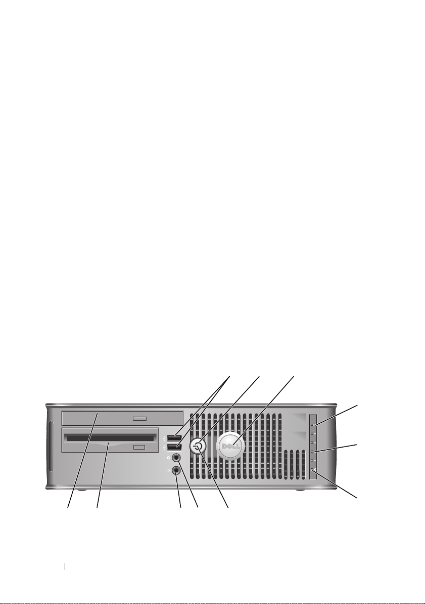
Small Form Factor Computer — Front View
11 10
26 Quick Reference Guide
2
1
7
89
3
4
5
6
Page 27

1 USB 2.0
connectors (2)
2 power button Press to turn on the computer.
3 Dell badge This badge can be rotated to match the orientation of your
4 hard drive
activity light
5 diagnostic lights Use the lights to help you troubleshoot a computer problem
6 LAN indicator
light
Use the front USB connectors for devices that you connect
occasionally, such as joysticks or cameras, or for bootable
USB devices (see "System Setup Program" in your online
User’s Guide for instructions about booting to a USB
device).
It is recommended that you use the back USB connectors
for devices that typically remain connected, such as printers
and keyboards.
NOTICE: To avoid losing data, do not turn off the
computer by pressing the power button. Instead,
perform an operating system shutdown. See "Turning Off
Your Computer" in your online User’s Guide for
instructions for more information.
NOTICE: If your operating system has ACPI enabled,
when you press the power button the computer will
perform an operating system shutdown.
computer. To rotate, place fingers around the outside of the
badge, press firmly, and turn the badge. You can also rotate
the badge using the slot provided near the bottom of the
badge.
This light flickers when the hard drive is being accessed.
based on the diagnostic code. For more information, see
"Diagnostic Lights" on page 55.
This light indicates that a LAN (local area network)
connection is established.
Quick Reference Guide 27
Page 28

7 power light The power light illuminates and blinks or remains solid to
indicate different operating states:
• No light — The computer is turned off.
• Steady green — The computer is in a normal operating
state.
• Blinking green — The computer is in a power-saving
mode.
See "Power Problems" in your
8 headphone
connector
9 microphone
connector
10 floppy drive bay
(optional)
11 optical drive
(optional)
• Blinking or solid amber —
online User’s Guide.
To exit from a power-saving mode, press the power button
or use the keyboard or the mouse if it is configured as a
wake device in the Windows Device Manager. For more
information about sleep modes and exiting from a powersaving mode, see "Power Management" in your online User’s
Guide.
See "System Lights" on page 54 for a description of light
codes that can help you troubleshoot problems with your
computer.
Use the headphone connector to attach headphones and
most kinds of speakers.
Use the microphone connector to attach a microphone.
Can contain an optional slimline floppy drive or optional
slimline media card reader.
Insert slimline optical drive (if supported) into this bay.
28 Quick Reference Guide
Page 29
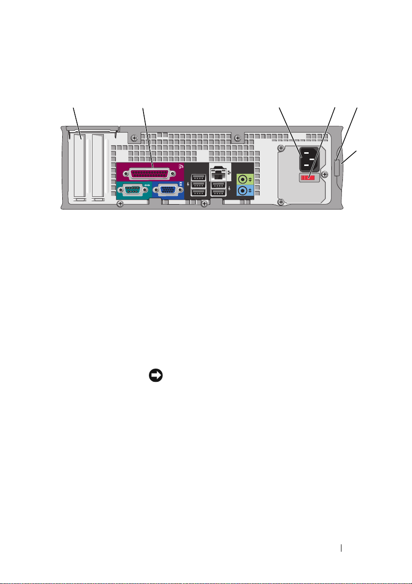
Small Form Factor Computer — Back View
1 card slots (2) Access connectors for any installed PCI and PCI Express
cards.
2 back-panel
connectors
3 power connector Insert the power cable.
4 voltage selection
switch
Plug serial, USB, and other devices into the appropriate
connectors (see "Small Form Factor Computer — BackPanel Connectors" on page 30).
Your computer may be equipped with a manual voltageselection switch. To help avoid damaging a computer with a
manual voltage selection switch, set the switch for the
voltage that most closely matches the AC power available in
your location.
51 2 3 4
6
NOTICE: In Japan, the voltage selection switch must be
set to the 115-V position even though the AC power
available in Japan is 100 V.
Also, ensure that your monitor and attached devices are
electrically rated to operate with the AC power available in
your location.
5 padlock ring Insert a padlock to lock the computer cover.
6 cover release
latch
Allows you to open the computer cover.
Quick Reference Guide 29
Page 30

Small Form Factor Computer — Back-Panel Connectors
13
98 7
1 parallel
connector
Connect a parallel device, such as a printer, to the parallel
connector. If you have a USB printer, plug it into a USB
connector.
24
NOTE: The integrated parallel connector is automatically disabled
if the computer detects an installed card containing a parallel
connector configured to the same address. For more information,
see "System Setup Program" in your online User’s Guide.
2 link integrity
light
• Green — A good connection exists between a 10-Mbps network
and the computer.
• Orange — A good connection exists between a 100-Mbps
network and the computer.
• Yellow — A good connection exists between a 1-Gbps
(or 1000-Mbps) network and the computer.
• Off — The computer is not detecting a physical connection to
the network.
5
6
30 Quick Reference Guide
Page 31

3 network
adapter
connector
4 network
activity light
5 line-out
connector
6 line-in
connector
7 USB 2.0
connectors
(5)
8 video
connector
To attach your computer to a network or broadband device,
connect one end of a network cable to either a network jack or
your network or broadband device. Connect the other end of the
network cable to the network adapter connector on the back
panel of your computer. A click indicates that the network cable
has been securely attached.
NOTE: Do not plug a telephone cable into the network connector.
On computers with a network connector card, use the connector
on the card.
It is recommended that you use Category 5 wiring and
connectors for your network. If you must use Category 3 wiring,
force the network speed to 10 Mbps to ensure reliable operation.
Flashes a yellow light when the computer is transmitting or
receiving network data. A high volume of network traffic may
make this light appear to be in a steady "on" state.
Use the green line-out connector to attach headphones and
most speakers with integrated amplifiers.
On computers with a sound card, use the connector on the card.
Use the line-in connector to attach a record/playback device
such as a cassette player, CD player, or VCR.
On computers with a sound card, use the connector on the card.
Use the back USB connectors for devices that typically remain
connected, such as printers and keyboards.
Plug the cable from your VGA-compatible monitor into the blue
connector.
NOTE: If you purchased an optional graphics card, this connector
will be covered by a cap. Do not remove the cap. Connect your
monitor to the connector on the graphics card.
NOTE: If you are using a graphics card that supports dual
monitors, use the y-cable that came with your computer.
Quick Reference Guide 31
Page 32

9 serial
connector
Connect a serial device, such as a handheld device, to the serial
port. The default designations are COM1 for serial connector 1
and COM2 for serial connector 2.
NOTE: There is only a serial connector 2 if the optional PS2/serial
adapter is used.
For more information, see "System Setup Program" in your
online User’s Guide for instructions.
Removing the Computer Cover
CAUTION: Before you begin any of the procedures in this section, follow the
safety instructions in the Product Information Guide.
CAUTION: To guard against electrical shock, always unplug your computer from
the electrical outlet before removing the cover.
Before You Begin
NOTICE: To avoid losing data, save and close any open files and exit any open
programs before you turn off your computer.
1
Shut down the operating system:
a
Save and close any open files, exit any open programs, click the
button, and then click
b
In the
Shut Down
window, select the
drop-menu, and then click
The computer turns off after the operating system shutdown process
finishes.
2
Ensure that the computer and any attached devices are turned off. If your
computer and attached devices did not automatically turn off when you
shut down your operating system, turn them off now.
Shut Down
OK
.
.
Shut Down
option from the
Start
Before Working Inside Your Computer
Use the following safety guidelines to help protect your computer from
potential damage and to help ensure your own personal safety.
CAUTION: Before you begin any of the procedures in this section, follow the
safety instructions in the Product Information Guide.
32 Quick Reference Guide
Page 33

CAUTION: Handle components and cards with care. Do not touch the components
or contacts on a card. Hold a card by its edges or by its metal mounting bracket.
Hold a component such as a processor by its edges, not by its pins.
NOTICE: Only a certified service technician should perform repairs on your
computer. Damage due to servicing that is not authorized by Dell is not covered by
your warranty.
NOTICE: When you disconnect a cable, pull on its connector or on its strain-relief
loop, not on the cable itself. Some cables have a connector with locking tabs; if you
are disconnecting this type of cable, press in on the locking tabs before you
disconnect the cable. As you pull connectors apart, keep them evenly aligned to
avoid bending any connector pins. Also, before you connect a cable, ensure that
both connectors are correctly oriented and aligned.
To avoid damaging the computer, perform the following steps before you
begin working inside the computer.
1
Turn off your computer.
NOTICE: To disconnect a network cable, first unplug the cable from your computer
and then unplug it from the network wall jack.
2
Disconnect any telephone or telecommunication lines from the computer.
3
Disconnect your computer and all attached devices from their electrical
outlets, and then press the power button to ground the system board.
4
If applicable, remove the computer stand (for instructions, see the
documentation that came with the stand).
CAUTION: To guard against electrical shock, always unplug your computer from
the electrical outlet before removing the cover.
5
Remove the computer cover:
• Remove the mini tower computer cover (see "Mini Tower Computer"
on page 34).
• Remove the desktop computer cover (see "Desktop Computer" on
page 36).
• Remove the small form factor computer cover (see "Small Form
Factor Computer" on page 38).
NOTICE: Before touching anything inside your computer, ground yourself by
touching an unpainted metal surface, such as the metal at the back of the computer.
While you work, periodically touch an unpainted metal surface to dissipate any
static electricity that could harm internal components.
Quick Reference Guide 33
Page 34

Mini Tower Computer
CAUTION: Before you begin any of the procedures in this section, follow the
safety instructions in the Product Information Guide.
CAUTION: To guard against electrical shock, always unplug your computer from
the electrical outlet before removing the computer cover.
1
Follow the procedures in "Before You Begin" on page 32.
2
If you have installed a padlock through the padlock ring on the back panel,
remove the padlock.
3
Lay the computer on its side.
4
Slide the cover release latch back as you lift the cover.
5
Grip the sides of the computer cover and pivot the cover up using the
hinge tabs as leverage points.
6
Remove the cover from the hinge tabs and set it aside on a soft
nonabrasive surface.
34 Quick Reference Guide
Page 35

1
2
3
4
1 security cable slot 2 cover release latch 3 padlock ring
4 computer cover
Quick Reference Guide 35
Page 36

Desktop Computer
CAUTION: Before you begin any of the procedures in this section, follow the
safety instructions in the Product Information Guide.
CAUTION: To guard against electrical shock, always unplug your computer from
the electrical outlet before removing the computer cover.
1
Follow the procedures in "Before You Begin" on page 32.
2
If you have installed a padlock through the padlock ring on the back panel,
remove the padlock.
3
Lay the computer on its side.
4
Slide the cover release latch back as you lift the cover.
5
Grip the sides of the computer cover and pivot the cover up using the
hinge tabs as leverage points.
6
Remove the cover from the hinge tabs and set it aside on a soft
nonabrasive surface.
36 Quick Reference Guide
Page 37

1 security cable slot 2 cover release latch 3 padlock ring
4 computer cover
1
2
3
4
Quick Reference Guide 37
Page 38

Small Form Factor Computer
CAUTION: Before you begin any of the procedures in this section, follow the
safety instructions in the Product Information Guide.
CAUTION: To guard against electrical shock, always unplug your computer from
the electrical outlet before removing the computer cover.
1
Follow the procedures in "Before You Begin" on page 32.
2
If you have installed a padlock through the padlock ring on the back panel,
remove the padlock.
3
Lay the computer on its side.
4
Slide the release latch back as you lift the cover.
5
Grip the sides of the computer cover and pivot the cover up using the
bottom hinges as leverage points.
6
Remove the cover from the hinge tabs and set it aside on a soft
nonabrasive surface.
CAUTION: Graphic card heat sinks can become very hot during normal operation.
Ensure that a graphic card heat sink has had sufficient time to cool before you
touch it.
38 Quick Reference Guide
Page 39

1 security cable slot 2 cover release latch 3 padlock ring
4 computer cover
1
2
3
4
Inside Your Computer
Mini Tower Computer
CAUTION: Before you begin any of the procedures in this section, follow the
safety instructions in the Product Information Guide.
CAUTION: To avoid electrical shock, always unplug your computer from the
electrical outlet before removing the computer cover.
Quick Reference Guide 39
Page 40

NOTICE: Be careful when opening the computer cover to ensure that you do not
accidentally disconnect cables from the system board.
4
3
2
1
10
1 drive release latch 2 optical drive 3 floppy drive
4 power supply 5 chassis intrusion
switch (optional)
7 card slots (4) 8 heat sink assembly 9 hard drive
10 front I/O panel
5
6
9
6 system board
7
8
40 Quick Reference Guide
Page 41

System Board Components
1
22
21
20
19
18
17
16
15
2
3
4
5
6
7
14
13 12 10
1 speaker connector
(INT_SPKR)
4 power connector
(PW_12V_A1)
11
2 processor socket
(CPU)
5 SATA drive
connectors (SATA2,
SATA3)
9
3 memory module
6 SATA drive
Quick Reference Guide 41
8
connectors
(DIMM_1, DIMM_2,
DIMM_3, DIMM_4)
connectors (SATA0,
SATA1)
Page 42

7 front-panel
connector
(FRONTPANEL)
10 CMOS reset jumper
(RTCRST)
13 PCI Express x16
connector (SLOT1)
16 PCI Express x1
connector (SLOT4)
19 floppy drive
connector (DSKT)
22 fan connector
(FAN_CPU)
Jumper Settings
Mini Tower Computer
8 power connector
(POWER1)
11 battery socket
(BATTERY)
14 standby power
(AUX_PWR_LED)
17 password jumper
(PSWD)
20 serial connector
(PS2/SER2)
9 intrusion switch
connector
(INTRUDER)
12 internal USB (USB1)
15 PCI connector
(SLOT2)
18 PCI connector
(SLOT3)
21 optional DVI-card
connector
(DVI_HDR)
42 Quick Reference Guide
Page 43

Jumper Setting Description
PSWD Password features are enabled
(default setting).
Password features are disabled.
jumpered unjumpered
Desktop Computer
CAUTION: Before you begin any of the procedures in this section, follow the
safety instructions in the Product Information Guide.
CAUTION: To avoid electrical shock, always unplug your computer from the
electrical outlet before removing the computer cover.
NOTICE: Be careful when opening the computer cover to ensure that you do not
accidentally disconnect cables from the system board.
Quick Reference Guide 43
Page 44

3
2
1
4
5
6
8
1 drive release latch 2 optical drive 3 power supply
4 chassis intrusion
switch (optional)
7 heat sink assembly 8 front I/O panel
5 system board 6 card slots (3)
7
44 Quick Reference Guide
Page 45

System Board Components
1
20
19
18
17
16
15
14
2
3
4
5
6
7
13
1 speaker connector
4 memory module
12
(INT_SPKR)
connectors
(DIMM_1, DIMM_2,
DIMM_3, DIMM_4)
10
2 processor socket
(CPU)
5 power connector
(POWER1)
8911
3 power connector
(PW_12V_A1)
6 SATA drive
connectors (SATA0,
SATA1, SATA2)
Quick Reference Guide 45
Page 46

7 front-panel connector
(FRONTPANEL)
10 battery socket
(BATTERY)
13 standby power
(AUX_PWR_LED)
16 password jumper
(PSWD)
19 optional DVI-card
connector
(DVI_HDR)
Jumper Settings
Desktop Computer
8 intrusion switch
connector
(INTRUDER)
11 internal USB
(USB1)
14 PCI connectors
(SLOT2, SLOT3)
17 floppy drive
connector (DSKT)
20 fan connector
(FAN_CPU)
9 CMOS reset jumper
(RTCRST)
12 PCI Express x16
connector (SLOT1)
15 PCI Express x1
connector (SLOT4)
18 serial connector
(PS2/SER2)
46 Quick Reference Guide
Page 47

Jumper Setting Description
PSWD Password features are enabled
(default setting).
Password features are disabled.
jumpered unjumpered
Small Form Factor Computer
CAUTION: Before you begin any of the procedures in this section, follow the
safety instructions in the Product Information Guide.
CAUTION: To avoid electrical shock, always unplug your computer from the
electrical outlet before removing the computer cover.
NOTICE: Be careful when opening the computer cover to ensure that you do not
accidentally disconnect cables from the system board.
3
2
1
9
4
5
6
7
8
Quick Reference Guide 47
Page 48

1 drive release latch 2 optical drive 3 power supply
4 chassis intrusion
switch (optional)
7 system board 8 heat sink assembly 9 front I/O panel
5 hard drive 6 card slots (2)
System Board Components
12
20
3
19
18
17
16
15
14
13
48 Quick Reference Guide
4
5
6
7
10
91112
8
Page 49

1 fan connector
(FAN_CPU)
4 memory module
connectors
(DIMM_1,
DIMM_2, DIMM_3,
DIMM_4)
7 front-panel
connector
(FRONTPANEL)
10 CMOS reset jumper
(RTCRST)
13 standby
(AUX_PWR_LED)
16 password jumper
(PSWD)
19 optional DVI-card
connector
(DVI_HDR)
2 processor socket
(CPU)
5 power connector
(POWER1)
8 fan connector
(FAN_HDD)
11 battery socket
(BATTERY)
14 PCI Express x16
connector (SLOT1)
17 serial connector
(PS2/SER2)
20 speaker connector
(INT_SPKR)
3 power connector
(PW_12V_A1)
6 SATA drive
connectors (SATA0,
SATA1)
9 intrusion switch
connector
(INTRUDER)
12 internal USB (USB1)
15 PCI connector
(SLOT2)
18 slimline floppy-drive
connector (DSKT)
Quick Reference Guide 49
Page 50

Jumper Settings
Small Form Factor Computer
Jumper Setting Description
PSWD Password features are enabled
(default setting).
Password features are disabled.
jumpered unjumpered
Solving Problems
Dell provides a number of tools to help you if your computer does not
perform as expected. For the latest troubleshooting information available for
your computer, see the Dell Support website at support.dell.com.
50 Quick Reference Guide
Page 51

If computer problems occur that require help from Dell, write a detailed
description of the error, beep codes, or diagnostics light patterns, record your
Express Service Code and Service Tag below, and then contact Dell from the
same location as your computer. For information on contacting Dell, see your
online User’s Guide.
For an example of the Express Service Code and Service Tag, see "Finding
Information" on page 5.
Express Service Code:___________________________
Service Tag:___________________________
Dell Diagnostics
CAUTION: Before you begin any of the procedures in this section, follow the
safety instructions in the Product Information Guide.
When to Use the Dell Diagnostics
If you experience a problem with your computer, perform the checks in
"Solving Problems" in your online User’s Guide and run the Dell Diagnostics
before you contact Dell for technical assistance. For information on
contacting Dell, see your online User’s Guide.
NOTICE: The Dell Diagnostics works only on Dell™ computers.
Enter system setup (see "System Setup Program" in your online User’s Guide
for instructions), review your computer’s configuration information, and
ensure that the device you want to test displays in system setup and is active.
Start the Dell Diagnostics from either your hard drive or from the optional
Drivers and Utilities media.
Starting the Dell Diagnostics From Your Hard Drive
The Dell Diagnostics is located on a hidden diagnostic utility partition on
your hard drive.
NOTE: If your computer cannot display a screen image, contact Dell (see your
online User’s Guide).
1
Shut down the computer. Turn on (or restart) your computer.
2
When the DELL™ logo appears, press <F12> immediately.
Quick Reference Guide 51
Page 52

NOTE: If you see a message stating that no diagnostics utility partition has been
found, run the Dell Diagnostics from your Drivers and Utilities media (optional).
If you wait too long and the operating system logo appears, continue to
wait until you see the Microsoft
®
Windows® desktop. Then shut down
your computer and try again.
3
When the boot device list appears, highlight
Boot to Utility Partition
press <Enter>.
4
When the Dell Diagnostics
Main Menu
appears, select the test you want
to run.
Starting the Dell Diagnostics From the Drivers and Utilities Media
1
Insert the
2
Shut down and restart the computer.
Drivers and Utilities
media.
When the DELL logo appears, press <F12> immediately.
If you wait too long and the operating system logo appears, continue to
wait until you see the Microsoft Windows desktop. Then shut down your
computer and try again.
NOTE: The next steps change the boot sequence for one time only. On the next
start-up, the computer boots according to the devices specified in the system setup
program.
3
When the boot device list appears, highlight the listing for the optical
drive and press <Enter>.
4
Select the listing for the optical drive option from the CD boot menu.
5
Select the option to boot from the optical drive from the menu that
appears.
6
Ty p e 1 to start the
7
Ty p e 2 to start the Dell Diagnostics.
8
Select
Run the 32 Bit Dell Diagnostics
Drivers and Utilities
media menu.
from the numbered list. If
multiple versions are listed, select the version appropriate for your
computer.
9
When the Dell Diagnostics
Main Menu
appears, select the test you want
to run.
and
52 Quick Reference Guide
Page 53

Dell Diagnostics Main Menu
1
After the Dell Diagnostics loads and the
Main Menu
screen appears, click
the button for the option you want.
Option Function
Express Test Performs a quick test of devices. This test typically takes 10 to
20 minutes and requires no interaction on your part. Run
Express Test first to increase the possibility of tracing the
problem quickly.
Extended Test Performs a thorough check of devices. This test typically takes
an hour or more and requires you to answer questions
periodically.
Custom Test Tests a specific device. You can customize the tests you want to
run.
Symptom Tree Lists the most common symptoms encountered and allows you
to select a test based on the symptom of the problem you are
having.
2
If a problem is encountered during a test, a message appears with an error
code and a description of the problem. Write down the error code and
problem description and follow the instructions on the screen.
If you cannot resolve the error condition, contact Dell. For information on
contacting Dell, see your online
User’s Guide
.
NOTE: The Service Tag for your computer is located at the top of each test
screen. If you contact Dell, technical support will ask for your Service Tag.
3
If you run a test from the
Custom Test
or
Symptom Tree
option, click the
applicable tab described in the following table for more information.
Tab Function
Results Displays the results of the test and any error conditions
encountered.
Errors Displays error conditions encountered, error codes, and the
problem description.
Help Describes the test and may indicate requirements for running the
test.
Quick Reference Guide 53
Page 54

Tab Function (continued)
Configuration Displays your hardware configuration for the selected device.
The Dell Diagnostics obtains configuration information for all
devices from system setup, memory, and various internal tests,
and it displays the information in the device list in the left pane
of the screen. The device list may not display the names of all the
components installed on your computer or all devices attached to
your computer.
Parameters You can customize the test by changing the test settings.
4
When the tests are completed, if you are running the Dell Diagnostics
from the
5
Close the test screen to return to the
Diagnostics and restart the computer, close the
Drivers and Utilities
media (optional), remove the CD or DVD.
Main Menu
screen. To exit the Dell
Main Menu
screen.
System Lights
Your power light may indicate a computer problem.
Power Light Problem Description Suggested Resolution
Solid green Power is on, and the
computer is operating
normally.
Blinking green The computer is in a
power-saving mode.
Blinks green
several times and
then turns off
A configuration error exists. See "Diagnostic Lights" on page 55
No corrective action is required.
Press the power button, move the
mouse, or press a key on the
keyboard to wake the computer.
to see if the specific problem is
identified.
54 Quick Reference Guide
Page 55

Power Light Problem Description Suggested Resolution
Solid yellow The Dell Diagnostics is
running a test, or a device
on the system board may be
faulty or incorrectly
installed.
Blinking yellow A power supply or system
board failure has occurred.
Solid green and a
beep code during
POST
Solid green
power light, no
beep code and
no video during
POST
Solid green
power light and
no beep code,
but the
computer locks
up during POST
A problem was detected
while the BIOS was
executing.
The monitor or the graphics
card may be faulty or
incorrectly installed.
An integrated system board
device may be faulty.
If the Dell Diagnostics is running,
allow the testing to complete.
See "Diagnostic Lights" on page 55
to see if the specific problem is
identified.
If the computer does not boot,
contact Dell for technical assistance.
For information on contacting Dell,
see your online
See "Diagnostic Lights" on page 55
to see if the specific problem is
identified.
See "Power Problems" in your online
User’s Guide.
For instructions on diagnosing the
beep code, see "Beep Codes" on
page 59. Also, see "Diagnostic
Lights" on page 55 to see if the
specific problem is identified.
See "Diagnostic Lights" on page 55
to see if the specific problem is
identified.
See "Diagnostic Lights" on page 55
to see if the specific problem is
identified. If the problem is not
identified, contact Dell for technical
assistance.
contacting Dell, see your online
User’s Guide
User’s Guide
For information on
.
.
Diagnostic Lights
CAUTION: Before you begin any of the procedures in this section, follow the
safety instructions located in the Product Information Guide.
Quick Reference Guide 55
Page 56

To help you troubleshoot a problem, your computer has four lights labeled
"1," "2," "3," and "4" on the front panel. The lights can be off or green. When
the computer starts normally, the patterns or codes on the lights change as
the boot process completes. If the POST portion of system boot completes
successfully, all four lights display solid green. If the computer malfunctions
during the POST process, the pattern displayed on the LEDs may help
identify where in the process the computer halted.
NOTE: The orientation of the diagnostic lights may vary depending on the system
type. The diagnostic lights can appear either vertical or horizontal.
Light Pattern Problem Description Suggested Resolution
The computer is in a normal off
condition, or a possible preBIOS failure has occurred.
The diagnostic lights are not lit
after the computer successfully
boots to the operating system.
A possible BIOS failure has
occurred; the computer is in
the recovery mode.
A possible processor failure has
occurred.
Plug the computer into a
working electrical outlet and
press the power button.
Run the BIOS Recovery utility,
wait for recovery completion,
and then restart the computer.
Reinstall the processor and
restart the computer.
56 Quick Reference Guide
Page 57

Light Pattern Problem Description Suggested Resolution
Memory modules are detected,
but a memory failure has
occurred.
A possible graphics card failure
has occurred.
• If you have one memory
module installed, reinstall it
and restart the computer (see
the online
instructions on how to
remove and install memory
modules).
• If you have two or more
memory modules installed,
remove the modules, reinstall
one module, and then restart
the computer. If the
computer starts normally,
reinstall an additional
module. Continue until you
have identified a faulty
module or reinstalled all
modules without error.
• If available, install properly
working memory of the same
type into your computer.
• If the problem persists,
contact Dell
• If the computer has a
graphics card, remove the
card, reinstall it, and then
restart the computer.
• If the problem still exists,
install a graphics card that
you know works and restart
the computer.
• If the problem persists or the
computer has integrated
graphics,
technical assistance.
information on contacting
Dell, see your online
Guide
User’s Guide
.
contact Dell for
.
for
For
User’s
Quick Reference Guide 57
Page 58

Light Pattern Problem Description Suggested Resolution
A possible floppy or hard drive
failure has occurred.
A possible USB failure has
occurred.
No memory modules are
detected.
Reseat all power and data
cables and restart the
computer.
Reinstall all USB devices, check
cable connections, and then
restart the computer.
• If you have one memory
module installed, reinstall it
and restart the computer (see
the online
instructions on how to
remove and install memory
modules).
• If you have two or more
memory modules installed,
remove the modules, reinstall
one module, and then restart
the computer. If the
computer starts normally,
reinstall an additional
module. Continue until you
have identified a faulty
module or reinstalled all
modules without error.
• If available, install properly
working memory of the same
type into your computer.
• If the problem persists,
contact Dell for technical
assistance.
on contacting Dell, see your
online
User’s Guide
For information
User’s Guide
for
.
58 Quick Reference Guide
Page 59

Light Pattern Problem Description Suggested Resolution
Memory modules are detected,
but a memory configuration or
compatibility error exists.
A failure has occurred.
This pattern also displays when
you enter the system setup
program and may not indicate
a problem (see "System Setup
Program" in your computer’s
online User’s Guide).
After POST is complete, all
four diagnostic lights turn
green briefly before turning off
to indicate normal operating
condition.
• Ensure that no
memory module/memory
connector placement
requirements
• Verify that the
modules
installing are compatible with
your computer.
• If the problem persists,
contact Dell for technical
assistance.
on contacting Dell, see your
User’s Guide
online
• Ensure that the cables are
properly connected to the
system board from the hard
drive, and optical drive.
• Check the computer message
that appears on your monitor
screen.
• If the problem persists,
contact Dell for technical
assistance.
on contacting Dell, see your
online
User’s Guide
None.
special
exist.
memory
that you are
For information
For information
.
.
Beep Codes
Your computer might emit a series of beeps during start-up if the monitor
cannot display errors or problems. This series of beeps, called a beep code,
identifies a problem.
Quick Reference Guide 59
Page 60

If your computer beeps during start-up:
1
Write down the beep code.
2
See "Dell Diagnostics" on page 51 to identify a more serious cause.
3
Contact Dell for technical assistance. For information on contacting Dell,
see your online
Code Cause
2 short, 1 long BIOS checksum error
1 long, 2 short Memory test failure (bad memory during memory sizing)
1 long, 3 short, 2 short No memory
1 short <F12> key pressed
User’s Guide
.
Resolving Software and Hardware Incompatibilities
If a device is either not detected during the operating system setup or is
detected but incorrectly configured, you can use the Hardware
Troubleshooter to resolve the incompatibility.
Windows Vista
1
Click
Start
2
Ty p e
hardware troubleshooter
<Enter> to start the search.
In the search results, select the option that best describes the problem and
follow the remaining troubleshooting steps.
and click
Help and Support.
in the search field and press
Windows XP
1
Click
Start→
2
Ty p e
hardware troubleshooter
Help and Support
<Enter> to start the search.
3
In the
Fix a Problem
4
In the
Hardware Troubleshooter
the problem and click
section, click
Next
60 Quick Reference Guide
.
in the search field and press
Hardware Troubleshooter
.
list, select the option that best describes
to follow the remaining troubleshooting steps.
Page 61

Restoring Your Operating System
The Microsoft Windows operating system provides System Restore to allow
you to return your computer to an earlier operating state (without affecting
data files) if changes to the hardware, software, or other system settings have
left the computer in an undesirable operating state. See the Windows Help
and Support Center for information on using System Restore.
NOTICE: Make regular backups of your data files. System Restore does not
monitor your data files or recover them.
Windows Vista
Starting System Restore
1
Click
Start .
2
In the
Start Search
NOTE: The User Account Control window may appear. If you are an
administrator on the computer, click Continue; otherwise, contact your
administrator to continue the desired action.
3
Click
Next
and follow the remaining prompts on the screen.
In the event that System Restore did not resolve the issue, you may undo the
last system restore.
Undoing the Last System Restore
box, type
System Restore
and press <Enter>.
NOTICE: Before you undo the last system restore, save and close all open files and
exit any open programs. Do not alter, open, or delete any files or programs until the
system restoration is complete.
1
Click
2
3
Start
In the
Start Search
Click
Undo my last restoration
.
box, type
System Restore
and click
Next
.
Quick Reference Guide 61
and press <Enter>.
Page 62

Windows XP
Creating a Restore Point
1
Click the
2
Click
3
Follow the instructions on the screen.
Restoring the Computer to an Earlier Operating State
NOTICE: Before you restore the computer to an earlier operating state, save and
close any open files and exit any open programs. Do not alter, open, or delete any
files or programs until the system restoration is complete.
1
Click the
To ol s
2
Ensure that
Next
3
Click a calendar date to which you want to restore your computer.
The
Start
button and click
System Restore
Start
, and then click
.
button, point to
System Restore
Restore my computer to an earlier time
.
Select a Restore Point
Help and Support
All Programs→
.
Accessories→
.
is selected and click
screen provides a calendar that allows you to
see and select restore points. All calendar dates with available restore
points appear in boldface type.
4
Select a restore point and click
Next
.
If a calendar date has only one restore point, then that restore point is
automatically selected. If two or more restore points are available, click the
restore point that you prefer.
System
5
Click
Next
.
The
Restoration Complete
screen appears after System Restore finishes
collecting data and then the computer restarts.
6
After the computer restarts, click OK.
To change the restore point, you can either repeat the steps using a different
restore point, or you can undo the restoration.
62 Quick Reference Guide
Page 63

Undoing the Last System Restore
NOTICE: Before you undo the last system restore, save and close all open files and
exit any open programs. Do not alter, open, or delete any files or programs until the
system restoration is complete.
1
Click the
Tools
2
Click
3
Click
The
4
After the computer restarts, click OK.
Enabling System Restore
Start
button, point to
, and then click
System Restore
Undo my last restoration
Next
.
System Restore
screen appears and the computer restarts.
All Programs→ Accessories→ System
.
and click
Next
.
If you reinstall Windows XP with less than 200 MB of free hard-disk space
available, System Restore is automatically disabled. To see if System Restore
is enabled:
1
Click the
2
Click
3
Click
4
Click the
5
Ensure that
Start
button and click
Control Pane l
Performance and Maintenance
System
.
System Restore
tab.
Turn off System Restore
.
.
is unchecked.
Reinstalling Your Microsoft Windows Operating System
To reinstall your operating system, see the instructions in the following
section that corresponds to the operating system your computer is running.
Windows Vista
The reinstallation process can take 1 to 2 hours to complete. After you
reinstall the operating system, you must also reinstall the device drivers, virus
protection program, and other software.
Save and close any open files and exit any open programs.
1
2
Insert the
3
Click
Operating System
Exit
if the
Install Windows
media.
message appears.
Quick Reference Guide 63
Page 64

4
Restart the computer.
When the DELL logo appears, press <F12> immediately.
NOTE: If you wait too long and the operating system logo appears, continue to
wait until you see the Microsoft
computer and try again.
NOTE: The next steps change the boot sequence for one time only. On the
next start-up, your computer boots according to the devices specified in the
system setup program.
5
When the boot device list appears, highlight
®
Windows® desktop; then, shut down your
CD/DVD/CD-RW Drive
and press <Enter>.
6
Press any key to
7
Follow the instructions on the screen to complete the installation.
Windows XP
NOTICE: You must use Windows XP Service Pack 1 or later when you reinstall your
operating system.
Before You Begin
Boot from CD-ROM
.
If you are considering reinstalling the Microsoft Windows operating system to
correct a problem with a newly installed driver, first try using Device Driver
Rollback (see "Using Windows Device Driver Rollback" on page 68 for more
information). If Device Driver Rollback does not resolve the problem, then
use System Restore (see "Restoring Your Operating System" on page 61 for
more information) to return your operating system to the operating state it
was in before you installed the new device driver.
NOTICE: Before performing the installation, back up all data files on your primary
hard drive. For conventional hard drive configurations, the primary hard drive is the
first drive detected by the computer.
To reinstall Windows XP, you need the following items:
•Dell™
•Dell
NOTE: The Drivers and Utilities media contains drivers that were installed during
Operating System
Drivers and Utilities
assembly of the computer. Use the Drivers and Utilities media to load any required
drivers.
media
media
64 Quick Reference Guide
Page 65

To reinstall Windows XP, perform all the steps in the following sections in the
order in which they are listed.
The reinstallation process can take 1 to 2 hours to complete. After you
reinstall the operating system, you must also reinstall the device drivers, virus
protection program, and other software.
NOTICE: The Operating System media provides options for reinstalling
Windows XP. The options can overwrite files and possibly affect programs installed
on your hard drive. Therefore, do not reinstall Windows XP unless a Dell technical
support representative instructs you to do so.
NOTICE: To prevent conflicts with Windows XP, disable any virus protection
software installed on your computer before you reinstall Windows XP. See the
documentation that came with the software for instructions.
Booting From the Operating System Media
1
Save and close any open files and exit any open programs.
2
Insert the
XP
3
Restart the computer.
4
Press <F12> immediately after the DELL™ logo appears.
Operating System
message appears.
media. Click
Exit
if
Install Windows
If the operating system logo appears, wait until you see the Windows
desktop, and then shut down the computer and try again.
5
Press the arrow keys to select
6
When the
Press any key to boot from CD
CD-ROM
, and press <Enter>.
message appears,
press any key.
Windows XP Setup
1
When the
set up Windows now
2
Read the information on the
Windows XP Setup
.
screen appears, press <Enter> to select
Microsoft Windows Licensing Agreement
screen, and press <F8> to accept the license agreement.
3
If your computer already has Windows XP installed and you want to
recover your current Windows XP data, type
r
to select the repair option,
and remove the media.
Quick Reference Guide 65
To
Page 66

4
If you want to install a new copy of Windows XP, press <Esc> to select
that option.
5
Press <Enter> to select the highlighted partition (recommended), and
follow the instructions on the screen.
The
Windows XP Setup
screen appears, and the operating system begins
to copy files and install the devices. The computer automatically restarts
multiple times.
NOTICE: Do not press any key when the following message appears: Press
Next
.
screen appears, select the
.
Personalize Your
window, enter a
any key to boot from the CD
NOTE: The time required to complete the setup depends on the size of the hard
drive and the speed of your computer.
6
When the
Regional and Language Options
settings for your location and click
7
Enter your name and organization (optional) in the
Software
8
At the
screen, and click
Computer Name and Administrator Password
Next
.
name for your computer (or accept the one provided) and a password, and
click
Next
.
9
If the
Modem Dialing Information
information and click
10
Enter the date, time, and time zone in the
window, and click
11
If the
Networking Settings
12
If you are reinstalling Windows XP Professional and you are prompted to
Next
Next
.
.
screen appears, click
screen appears, enter the requested
Date and Time Settings
Typical
and click
provide further information regarding your network configuration, enter
your selections. If you are unsure of your settings, accept the default
selections.
Windows XP installs the operating system components and configures the
computer. The computer automatically restarts.
Next
.
NOTICE: Do not press any key when the following message appears: Press
any key to boot from the CD
13
When the
14
When the
Internet?
Welcome to Microsoft
How will this computer connect to the
message appears, click
.
screen appears, click
Skip
.
Next
66 Quick Reference Guide
.
Page 67

15
When the
at this time
16
When the
Ready to register with Microsoft?
and click
Who will use this computer?
Next
.
screen appears, you can enter up
screen appears, select
to five users.
17
Click
Next
.
18
Click
Finish
to complete the setup, and remove the media.
19
Reinstall the appropriate drivers with the
20
Reinstall your virus protection software.
21
Reinstall your programs.
NOTE: To reinstall and activate your Microsoft Office or Microsoft Works Suite
programs, you need the Product Key number located on the back of the Microsoft
Office or Microsoft Works Suite media sleeve.
Drivers and Utilities
media.
Using the Drivers and Utilities Media
NOTICE: The Drivers and Utilities media may contain drivers for operating systems
that are not on your computer. Ensure that you are installing software appropriate
for your operating system.
Many drivers, such as the keyboard driver, come with your Microsoft
Windows operating system. You may need to install drivers if you:
• Upgrade your operating system.
• Reinstall your operating system.
• Connect or install a new device.
No, not
Identifying Drivers
If you experience a problem with any device, identify whether the driver is the
source of your problem and, if necessary, update the driver.
Windows Vista
1
Click
2
Click
®
Start
Properties→ Device Manager
NOTE: The User Account Control window may appear. If you are an
administrator on the computer, click Continue; otherwise, contact your
administrator to continue.
and right-click
Computer
.
.
Quick Reference Guide 67
Page 68

Scroll down the list to see if any device has an exclamation point (a yellow
circle with a [!]) on the device icon.
If an exclamation point is next to the device name, you may need to reinstall
the driver or install a new driver (see "Reinstalling Drivers and Utilities" on
page 68).
Windows® XP
1
Click
Start→
2
Under
System
3
In the
System Properties
Manager
Reinstalling Drivers and Utilities
NOTICE: The Dell Support website at support.dell.com and your Drivers and
Utilities media provide approved drivers for Dell™ computers. If you install drivers
obtained from other sources, your computer might not work correctly.
Using Windows Device Driver Rollback
Control Panel
Pick a Category
.
.
.
, click
Performance and Maintenance
window, click the
Hardware
, and click
tab, and click
Device
If a problem occurs on your computer after you install or update a driver, use
Windows Device Driver Rollback to replace the driver with the previously
installed version.
If Device Driver Rollback does not resolve the problem, then use System
Restore (see "Restoring Your Operating System" on page 61) to return your
computer to the operating state that existed before you installed the new
driver.
Windows Vista:
1
Click
2
Start
Click
Properties→ Device Manager
and right-click
Computer
.
.
NOTE: The User Account Control window may appear. If you are an
administrator on the computer, click Continue; otherwise, contact your
administrator to enter the Device Manager.
3
Right-click the device for which the new driver was installed and click
Properties
4
Click the
.
Drivers
tab→ Roll Back Driver
.
68 Quick Reference Guide
Page 69

Windows XP:
1
Click
Start→
2
Right-click the device for which the new driver was installed and click
Properties
3
Click the
Manually Reinstalling Drivers
My Computer→ Properties→ Hardware→
.
Drivers
tab→
Roll Back Driver
.
Device Manager
After extracting the driver files to your hard drive as described in the previous
section:
Windows Vista:
1
Click
Start
2
Click
Properties→ Device Manager
NOTE: The User Account Control window may appear. If you are an
administrator on the computer, click Continue; otherwise, contact your
administrator to enter the Device Manager.
3
Double-click the type of device for which you are installing the driver (for
example,
4
Double-click the name of the device for which you are installing the driver.
5
Click the
software
6
Click
Browse
and right-click
Computer
.
.
Audio
or
Video
).
Driver
tab→
Update Driver→ Browse my computer for driver
.
and browse to the location to which you previously copied
the driver files.
7
When the name of the appropriate driver appears, click the name of the
8
driver
Click
→ OK→
Finish
Next
.
and restart your computer.
Windows XP:
1
Click
Start→ My Computer→ Properties→ Hardware→ Device Manager
2
Double-click the type of device for which you are installing the driver (for
Audio
or
Video
example,
3
Double-click the name of the device for which you are installing the driver.
4
Click the
5
Click
Driver
tab→
Install from a list or specific location (Advanced)→ Next
).
Update Driver
.
.
.
.
Quick Reference Guide 69
Page 70

6
Click
Browse
and browse to the location to which you previously copied
the driver files.
7
When the name of the appropriate driver appears, click
8
Click
Finish
and restart your computer.
Next
.
70 Quick Reference Guide
Page 71

Index
B
beep codes, 59
C
CDs
operating system, 8
computer
restore to previous state, 61
conflicts
software and hardware
incompatibilities, 60
cover
opening, 38
removing, 32
D
Dell Diagnostics, 51
Dell support site, 9
diagnostics
beep codes, 59
Dell Diagnostics, 51
documentation
End User License Agreement, 6
ergonomics, 6
online, 9
Product Information Guide, 6
regulatory, 6
safety, 6
User’s Guide, 6
warranty, 6
drivers
identifying, 67
reinstalling, 68
Drivers and Utilities CD, 5
E
End User License Agreement, 6
ergonomics information, 6
error messages
beep codes, 59
system lights, 54
H
hardware
beep codes, 59
conflicts, 60
Dell Diagnostics, 51
Hardware Troubleshooter, 60
Help and Support Center, 10
help file
Windows Help and Support
Center, 10
Index 71
Page 72

I
installing parts
before you begin, 32
IRQ conflicts, 60
L
labels
Microsoft Windows, 7
Service Tag, 7
problems. See troubleshooting
Product Information Guide, 6
R
regulatory information, 6
reinstalling
Windows Vista, 63
Windows XP, 64
lights
power, 22, 28
system, 54
M
motherboard. See system board
O
operating system
reinstalling, 8
Operating System CD, 8
P
power
light, 22, 28
power light
diagnosing problems with, 54
S
safety instructions, 6
Service Tag, 7
software
conflicts, 60
support website, 9
system board, 40, 45, 48
System Restore, 61
T
troubleshooting
beep codes, 59
conflicts, 60
Dell Diagnostics, 51
Hardware Troubleshooter, 60
Help and Support Center, 10
restore to previous state, 61
system lights, 54
problems
restore to previous state, 61
72 Index
Page 73

U
User’s Guide, 6
W
warranty information, 6
Windows Vista
Hardware Troubleshooter, 60
Help and Support Center, 10
reinstalling, 63
System Restore, 61
Windows XP
Device Driver Rollback, 68
Hardware Troubleshooter, 60
Help and Support Center, 10
reinstalling, 8, 64
System Restore, 61
Index 73
Page 74

74 Index
Page 75

Stručná referenční příručka
Dell™ OptiPlex™ 740
Modely DCSM, DCNE, DCCY
www.dell.com | support.dell.com
Page 76

Poznámky, upozornění a varování
POZNÁMKA:
POZNÁMKA označuje důležité informace, které pomáhají lepšímu využití
počítače.
UPOZORNĚNÍ:
UPOZORNĚNÍ označuje nebezpečí poškození hardwaru nebo ztráty dat
a popisuje, jak se lze problému vyhnout.
VÝSTRAHA: VÝSTRAHA upozorňuje na potenciální poškození majetku a riziko
úrazu nebo smrti.
Pokud jste si zakoupili počítač řady Dell™, v tomto dokumentu neplatí odkazy
na operační systémy Microsoft
®
Windows®.
____________________
Informace v tomto dokumentu se mohou bez předchozího upozornění změnit.
© 2008 Dell Inc. Všechna práva vyhrazena.
Jakákoli reprodukce bez předchozího písemného povolení společnosti Dell Inc. je přísně zakázána.
Ochranné známky použité v tomto textu: Dell, OptiPlex a logo DELL jsou ochranné známky
společnosti Dell Inc.; Microsoft, W indows, W indows V ista a tlačítko Start systému Windows Vista jsou
registrované ochranné známky společnosti Microsoft Corporation.
Ostatní ochranné známky a názvy mohou být v tomto dokumentu použity buď v souvislosti
s organizacemi, které si na tyto známky a názvy činí nárok, nebo s jejich produkty. Společnost Dell
Inc. si nečiní nárok na jiné ochranné známky a názvy než své vlastní.
Modely DCSM, DCNE, DCCY
Leden 2008 P/N CR008 Rev. A01
Page 77

Obsah
Vyhledání informací . . . . . . . . . . . . . . . . . . . 79
Instalace počítače
Pohledy na počítač
Počítač typu minivěž – pohled zepředu
Počítač typu minivěž – pohled zezadu
Počítač typu minivěž – konektory na zadním panelu
Stolní počítač – pohled zepředu
Stolní počítač – pohled zezadu
Stolní počítač – konektory na zadním panelu
Úsporný stolní počítač – pohled zepředu
Úsporný počítač – pohled zezadu
Úsporný počítač – konektory na zadním panelu
. . . . . . . . . . . . . . . . . . . . 84
. . . . . . . . . . . . . . . . . . . . 88
. . . . . . . .
. . . . . . . .
. . . . . . . . . . .
. . . . . . . . . . . .
. . . . .
. . . . . .
. . . . . . . . .
.
. .
88
91
93
95
97
98
101
103
104
Demontáž krytu počítače . . . . . . . . . . . . . . . 106
Než začnete
Počítač typu minivěž
Stolní počítač
Počítač malého formátu
. . . . . . . . . . . . . . . . . . . .
. . . . . . . . . . . . . . . .
. . . . . . . . . . . . . . . . . . .
. . . . . . . . . . . . . .
106
108
110
112
Uvnitř počítače. . . . . . . . . . . . . . . . . . . . . 113
Počítač typu minivěž
Stolní počítač
Úsporný počítač
. . . . . . . . . . . . . . . .
. . . . . . . . . . . . . . . . . . .
. . . . . . . . . . . . . . . . . .
113
117
121
Řešení problémů . . . . . . . . . . . . . . . . . . . . 124
Diagnostický nástroj Dell Diagnostics
Systémové indikátory
. . . . . . . . . . . . . . .
. . . . . . . .
125
128
Diagnostické indikátory . . . . . . . . . . . . . . . . 130
Zvukové signály
. . . . . . . . . . . . . . . . . .
134
Obsah
77
Page 78

Odstraňování nekompatibility softwaru a
hardwaru
Obnovení operačního systému
. . . . . . . . . . . . . . . . . . . . . .
. . . . . . . . . . .
Přeinstalace operačního systému
Microsoft Windows
Používání média s ovladači a nástroji
. . . . . . . . . . . . . . . .
. . . . . . . .
135
136
138
142
Rejstřík
. . . . . . . . . . . . . . . . . . . . . . . . . . . . .
147
78
Obsah
Page 79

Vyhledání informací
POZNÁMKA:
počítačem dodána. Některé funkce nebo média nemusejí být v některých zemích
kdispozici.
POZNÁMKA:
Jaké informace hledáte? Zde je naleznete
• Diagnostický program pro počítač
• Ovladače pro počítač
• Dokumentace k počítači
• Dokumentace k zařízení
• Software DSS (Desktop System
Software)
Některé funkce nebo média jsou volitelná a nemusela být s tímto
Doplňkové informace byly pravděpodobně dodány s počítačem.
Médium s ovladači a nástroji
POZNÁMKA:
může být volitelné a nemusí být s počítačem
dodáno.
Dokumentace a ovladače jsou již
v počítači nainstalovány. Médium Drivers
and Utilities slouží k přeinstalaci ovladačů
(viz část „Používání média s ovladači a
nástroji“ na straně 142), ke spouštění
diagnostického programu Dell
Diagnostics (viz část „Diagnostický
nástroj Dell Diagnostics“ na straně 125)
nebo pro přístup k dokumentaci.
Médium
Drivers and Utilities
Na médiu (disku CD nebo DVD) mohou
být také soubory Readme, které obsahují
nejnovější informace o technických
změnách počítače nebo rozšířené
referenční a technické materiály pro
techniky a zkušené uživatele.
POZNÁMKA:
dokumentaci lze nalézt na adrese
support.dell.com
Aktualizace ovladačů a
.
Stručná referenční příručka
79
Page 80

Jaké informace hledáte? Zde je naleznete
• Informace o záruce
• Podmínky (jen USA)
• Bezpečnostní pokyny
• Informace o předpisech
• Informace o ergonomii
• Licenční smlouva s koncovým
uživatelem
Informační příručka produktu Dell™
• Odstraňování a výměna součástí
• Technické údaje
• Konfigurace systému
• Odstraňování a řešení problémů
Příručka uživatele Dell™ OptiPlex™
Centrum pro nápovědu a odbornou pomoc
Microsoft Windows
1
Klepněte na tlačítko
Nápověda a odborná pomoc
Uživatelské a systémové příručky
→
Systémové příručky.
Dell
2
Klepněte na uživatelskou příručku pro
váš počítač.
Příručka uživatele je také dostupná na
volitelném médiu Drivers and Utilities.
Start
→
→
80
Stručná referenční příručka
Page 81

Jaké informace hledáte? Zde je naleznete
• Servisní štítek a kód expresní služby
• Licenční štítek operačního systému
Microsoft Windows
Servisní štítek a licence systému
Microsoft
®
Windows®
Tyto štítky jsou umístěny na vašem
počítači.
• Při používání webové stránky
support.dell.com
podpory použijte servisní štítek
k identifikaci počítače.
• Zadejte kód expresní služby, aby vaše
volání mohlo být při kontaktování
podpory přesměrováno.
nebo kontaktování
Stručná referenční příručka
81
Page 82

Jaké informace hledáte? Zde je naleznete
• Nová instalace operačního systému
Médium Operating system
POZNÁMKA:
mohou být volitelná a možná nebyla s vaším
počítačem dodána.
Operační systém je v počítači již
nainstalován. Když budete chtít
přeinstalovat operační systém, použijte
médium Operating system. Viz část
„Přeinstalace operačního systému
Microsoft Windows“ na straně 138.
Po přeinstalaci operačního systému
můžete pomocí volitelného média Drivers
and Utilities přeinstalovat ovladače
zařízení dodaných s počítačem.
Štítek s kódem operačního systému je
umístěn na počítači.
POZNÁMKA:
objednaného operačního systému.
Média Operating system
Barva média se liší podle
82
Stručná referenční příručka
Page 83

Jaké informace hledáte? Zde je naleznete
• Řešení – tipy a rady pro odstraňování
problémů, články odborníků, časté
dotazy a školení online
• Community (Veřejnost) – Online
diskuse s ostatními zákazníky
společnosti Dell
• Upgrades (Nejnovější verze) –
Informace o nejnovějších verzích pro
součásti, jako je paměů, pevný disk a
operační systém
• Péče o zákazníky – Kontaktní
informace, servisní požadavek a stav
objednávky, záruka a informace o
opravách
• Servis a podpora – Stav servisního
požadavku a historie odborné podpory,
servisní smlouva, online diskuse
stechnickou podporou
• Reference – Dokumentace k počítači,
podrobnosti o individuální konfiguraci
počítače, technické údaje produktů a
oficiální dokumenty
• Soubory ke stažení – Certifikované
ovladače, opravy a aktualizace softwaru
• Desktop System Software (DSS) – Při
přeinstalaci operačního systému
v počítači byste také měli přeinstalovat
nástroj DSS. Nástroj DSS poskytuje
důležité aktualizace operačního
systému a podporu pro disketové
jednotky USB Dell™ 3,5, procesory,
optické jednotky a zařízení USB.
Nástroj DSS je nezbytný pro správné
fungování vašeho počítače Dell. Tento
software automaticky rozpozná počítač
a operační systém a nainstaluje
aktualizace, které odpovídají
individuální konfiguraci.
Internetová stránka podpory Dell –
support.dell.com
POZNÁMKA:
obchodního segmentu se zobrazí příslušná
stránka odborné pomoci.
Stažení nástroje Desktop System
Software:
1
Přejděte na webovou stránku
support.dell.com
obchodní segment a zadejte údaj ze
servisního štítku.
2
Vyberte položku
(Ovladače a soubory ke stažení) a
klepněte na tlačítko
3
Klepněte na příslušný operační systém a
vyhledejte klíčové slovo
Software
.
POZNÁMKA:
webových stránek
může lišit podle provedených voleb.
Po vybrání oblasti nebo
, vyberte oblast nebo
Drivers & Downloads
Go
(Přejít).
Desktop System
Uživatelské rozhraní
support.dell.com
se
Stručná referenční příručka
83
Page 84

Jaké informace hledáte? Zde je naleznete
• Práce se systémem Windows Vista®
nebo Windows
• Práce s programy a soubory
• Individuální přizpůsobení pracovní
plochy
®
XP
Centrum pro nápovědu a odbornou pomoc
systému Windows
1
Část Nápověda a odborná pomoc
systému Windows otevřete takto:
•
V systému Windows Vista
tlačítko Start
podpora
V systému Windows XP
•
tlačítko
pomoc
2
Zadejte slovo nebo slovní spojení, které
popisuje váš problém, a klepněte na
ikonu šipky.
3
Klepněte na téma popisující vaše potíže.
4
Postupujte podle pokynů na obrazovce.
→
Nápověda a
.
klepněte na
Start
→ Nápověda a odborná
.
Instalace počítače
VÝSTRAHA: Před prováděním některého z postupů uvedených v této části si
přečtěte bezpečnostní pokyny v Informační příručce produktu.
UPOZORNĚNÍ:
modemu), připojte příslušný kabel ke kartě,
Pokud je v počítači nainstalována karta pro rozšíření (například karta
nikoli
ke konektoru na zadním panelu.
klepněte na
UPOZORNĚNÍ:
příliš blízko ke zdi nebo některé části nábytku, což by mohlo bránit cirkulaci vzduchu okolo
skříně.
POZNÁMKA:
s počítačem, si přečtěte dokumentaci dodanou se zařízením nebo softwarem nebo se
obrat’te na výrobce a ověřte, zda dané zařízení nebo software jsou kompatibilní s tímto
počítačem a operačním systémem.
84
Stručná referenční příručka
Aby si mohl počítač udržovat správnou provozní teplotu, neumíst’ujte jej
Před instalací zařízení nebo softwaru, které nebyly dodány společně
Page 85

Aby byla zajištěna správná instalace počítače, musíte provést všechny kroky.
Postupujte podle příslušných obrázků, které doplňují pokyny.
UPOZORNĚNÍ:
1
Připojte klávesnici a myš.
UPOZORNĚNÍ:
telefonní linky může sít’ový adaptér poškodit.
2
Připojte telefonní linku nebo sít’ový kabel.
Nezkoušejte používat současně myš PS/2 a USB.
Nepřipojujte telefonní linku ke konektoru sít’ového adaptéru. Napětí
Připojte sít’ový kabel k sít’ovému konektoru (nikoli telefonní linku).
Používáte-li doplňkový modem, připojte telefonní linku k modemu.
3
Připojte monitor pomocí POUZE JEDNOHO z následujících kabelů: bílý
kabel DVI nebo modrý kabel VGA (nepřipojujte oba kabely ke stejnému
počítači).
Nasad’te a opatrně připojte kabel monitoru – zabraňte ohnutí kolíků.
Utáhněte ruční šrouby na kabelových konektorech.
POZNÁMKA:
straně obrazovky. Informace o umístění konektorů najdete v dokumentaci dodané
s monitorem.
U některých monitorů se konektor videa nachází na spodní zadní
Stručná referenční příručka
85
Page 86

4
Připojte reproduktory.
UPOZORNĚNÍ:
zadní straně počítače, pokud je počítač přepínačem napětí vybaven) na napětí, které
nejlépe odpovídá střídavému napětí dostupnému ve vaší lokalitě.
UPOZORNĚNÍ:
v této zemi k dispozici střídavý proud o napětí 100 V.
POZNÁMKA:
5
Zkontrolujte, zda poloha přepínače napětí odpovídá napětí, které je
Aby nedošlo k poškození počítače, nastavte ruční přepínač napětí (na
V Japonsku musí být přepínač napětí nastaven v poloze 115 V, ačkoli je
Zdroj napájení počítače nemusí být přepínačem napětí vybaven.
kdispozici.
Tento počítač je vybaven ručním přepínačem napětí. U počítačů, které
jsou na zadním panelu vybaveny přepínačem napětí, je třeba ručně
nastavit správné provozní napětí.
86
Stručná referenční příručka
Page 87

6
Připojte napájecí kabely k počítači, monitoru a k zařízením; opačné konce
napájecích kabelů připojte do elektrických zásuvek.
Stručná referenční příručka
87
Page 88

Pohledy na počítač
Počítač typu minivěž – pohled zepředu
10
9
8
1
2
3
4
5
6
7
88
Stručná referenční příručka
Page 89

1 optická
jednotka
(volitelná)
2 pozice pro
disketovou
jednotku
(volitelná)
3 konektory USB
2.0 (2)
4 kontrolka
místní sítě LAN
5 diagnostické
kontrolky
6 tlačítko
napájení
Vložte do tohoto oddělení optickou jednotku (pokud je
podporována).
Může obsahovat disketovou jednotku nebo volitelnou čtečku
pamět’ových karet.
Konektory USB na přední straně používejte pro příležitostně
připojovaná zařízení, jakou jsou pákové ovladače nebo
fotoaparáty, nebo pro zaváděcí zařízení USB (viz část
„Nastavení systému“ v Příručce uživatele online, kde naleznete
další informace o zavádění ze zařízení USB).
Zařízení, která běžně zůstávají připojená (například tiskárny
nebo klávesnice), doporučujeme připojit k zadním USB
konektorům.
Tento indikátor ukazuje, že bylo navázáno připojení k místní
síti (LAN).
Pomocí diagnostických kódů těchto kontrolek můžete
odstraňovat problémy s počítačem. Další informace najdete
v části „Diagnostické indikátory“ na straně 130.
Stisknutím tohoto tlačítka zapnete počítač.
UPOZORNĚNÍ:
počítač stisknutím vypínače. Místo toho řádně ukončete
operační systém. Více informací naleznete v části „Vypnutí
počítače“ v
Aby se zabránilo ztrátě dat, nevypínejte
Příručce uživatele
online.
UPOZORNĚNÍ:
ACPI, po stisknutí vypínače počítač provede řádné ukončení
operačního systému.
Pokud operační systém podporuje rozhraní
Stručná referenční příručka
89
Page 90

7 kontrolka
napájení
8 indikátor
činnosti
pevného disku
9 konektor
sluchátek
10 konektor pro
mikrofon
Blikáním a svícením signalizuje indikátor napájení různé
provozní stavy:
• Nesvítí – Počítač je vypnutý.
• Svítí zeleně – Počítač je zapnutý a pracuje normálně.
• Bliká zeleně – Počítač se nachází v úsporném režimu.
• Bliká nebo svítí žlutě – Pokyny naleznete v části „Problémy
s napájením“ v
Chcete-li ukončit úsporný režim, stiskněte vypínač nebo
použijte klávesnici nebo myš (pokud jsou tato zařízení ve
Správci zařízení systému Windows nakonfigurována pro
buzení). Další informace o režimu spánku a ukončení
úsporného režimu naleznete v části „Řízení proudu“ v Příručce
uživatele online.
V části „Systémové indikátory“ na straně 128 jsou popsány
kódy indikátoru, které vám mohou pomoci při odstraňování
problému s počítačem.
Tento indikátor bliká během přistupování k pevnému disku.
Ke konektoru sluchátek můžete připojit sluchátka a většinu
typů reproduktorů.
Ke konektoru mikrofonu můžete připojit mikrofon.
Příručce uživatele
online.
90
Stručná referenční příručka
Page 91

Počítač typu minivěž – pohled zezadu
1
2
3
4
5
6
1 západka pro
uvolnění krytu
počítače
2 kroužek zámku Nasad’te kladku a zamkněte kryt počítače.
Tato západka slouží k otevření krytu počítače.
Stručná referenční příručka
91
Page 92

3 přepínač napětí Počítač může být vybaven přepínačem pro ruční výběr
napětí.
Abyste přepínačem pro ruční výběr napětí nepoškodili
počítač, nastavte přepínač na napětí, které se nejvíce
shoduje s napájením střídavého proudu v daném místě.
UPOZORNĚNÍ:
nastaven v poloze 115 V, ačkoli je v této zemi k dispozici
střídavý proud o napětí 100 V.
Také zkontrolujte, zda jmenovité napětí monitoru a
připojených zařízení odpovídá napětí střídavého proudu,
který je ve vaší oblasti k dispozici.
4 konektor napájení Připojte napájecí kabel.
5 konektory na
zadním panelu
6 patice pro karty (4) Přístupové konektory všech nainstalovaných karet PCI a PCI
Připojte sériová, USB a jiná zařízení do příslušných
konektorů. Viz část „Počítač typu minivěž – konektory na
zadním panelu“ na straně 93.
Express.
V Japonsku musí být přepínač napětí
92
Stručná referenční příručka
Page 93

Počítač typu minivěž – konektory na zadním panelu
13
98 7
1 paralelní
konektor
2 kontrolka
integrity linky
K paralelnímu portu počítače připojte paralelní zařízení,
jako například tiskárnu. Máte-li k dispozici USB tiskárnu,
připojte ji k USB konektoru.
POZNÁMKA:
s paralelním konektorem, který je nakonfigurován na stejnou
adresu, bude integrovaný paralelní konektor automaticky zakázán.
Další informace a pokyny naleznete v části „Program nastavení
systému“ v
• Zelená – Existuje dobré spojení mezi sítí 10 Mb/s a
počítačem.
• Oranžová – Existuje dobré spojení mezi sítí 100 Mb/s a
počítačem.
• Žlutá – Mezi sítí 1000 Mb/s (1 Gb/s) a počítačem existuje
dobré spojení.
• Nesvítí – Počítač nerozpoznal fyzické připojení k síti.
Jestliže počítač rozpozná nainstalovanou kartu
Příručce uživatele
24
online.
5
6
Stručná referenční příručka
93
Page 94

3 konektor sít’ového
adaptéru
4 kontrolka aktivity
sítě
5 konektor
linkového
výstupu
6 konektor
linkového vstupu
7 konektory USB
2.0 (5)
8 konektor
zobrazovacího
zařízení
Chcete-li připojit počítač k sít’ovému nebo
širokopásmovému zařízení, připojte jeden konec sít’ového
kabelu k sít’ové zásuvce nebo k sít’ovému nebo
širokopásmovému zařízení. Druhý konec sít’ového kabelu
připojte ke konektoru sít’ového adaptéru na zadním panelu
počítače. Pro správné připojení je třeba sít’ový kabel
zacvaknout.
POZNÁMKA:
U počítačů s kartou se sít’ovým konektorem použijte
konektor na kartě.
Pro sít’ovou kabeláž doporučujeme použít kabely a konektory
kategorie 5. Pokud musíte použít kabeláž kategorie 3, musíte
pro zajištění spolehlivého provozu nastavit rychlost sítě na
10 Mb/s.
Bliká žlutě, když počítač přijímá nebo vysílá sít’ová data. Při
intenzivním sít’ovém provozu se může zdát, že tato
kontrolka takřka svítí.
K zelenému výstupnímu linkovému konektoru můžete
připojit sluchátka a většinu reproduktorových soustav se
zabudovaným zesilovačem.
U počítačů se zvukovou kartou používejte konektor na kartě.
Pomocí linkového konektoru připojte nahrávací/přehrávací
zařízení, například kazetový přehrávač, přehrávač CD nebo
videorekordér.
U počítačů se zvukovou kartou používejte konektor na kartě.
Zařízení, která běžně zůstávají připojená (například tiskárny
nebo klávesnice), doporučujeme připojit k zadním USB
konektorům.
Připojte kabel od monitoru kompatibilního se standardem
VGA do modrého konektoru.
POZNÁMKA:
bude tento konektor opatřen chráničkou. Neodstraňujte chráničku.
Připojte monitor ke konektoru na grafické kartě.
POZNÁMKA:
monitory, použijte rozdvojku, která byla dodána s počítačem.
K sít’ovému konektoru nepřipojujte telefonní kabel.
Pokud jste zakoupili doplňkovou grafickou kartu,
Používáte-li grafickou kartu, která podporuje duální
94
Stručná referenční příručka
Page 95

9 konektor
sériového
rozhraní
K sériovému portu připojte některé sériové zařízení,
například příruční počítač. Ve výchozím nastavení je port
COM1 přiřazen k sériovému konektoru 1 a port COM2
k sériovému konektoru 2.
Další informace naleznete v části „Program nastavení
systému“ v Příručce uživatele online.
Stolní počítač – pohled zepředu
1 konektory USB
2.0 (2)
1
89
Konektory USB na přední straně používejte pro
příležitostně připojovaná zařízení, jakou jsou pákové
ovladače nebo fotoaparáty, nebo pro zaváděcí zařízení USB
(viz část „Program nastavení systému“ v Příručce uživatele
online, kde naleznete další informace o zavádění ze
zařízení USB).
Zařízení, která běžně zůstávají připojená (například
tiskárny nebo klávesnice), doporučujeme připojit k zadním
konektorům USB.
2
7
3
5
4611 10
Stručná referenční příručka
95
Page 96

2 kontrolka místní
sítě LAN
3 tlačítko napájení Stisknutím tohoto tlačítka zapnete počítač.
Tento indikátor ukazuje, že bylo navázáno připojení
k místní síti (LAN).
UPOZORNĚNÍ:
počítač stisknutím vypínače. Místo toho řádně ukončete
operační systém. Další informace naleznete v části
„Vypnutí počítače“ v
Aby se zabránilo ztrátě dat, nevypínejte
Příručce uživatele
online.
UPOZORNĚNÍ:
rozhraní ACPI, po stisknutí vypínače počítač provede řádné
ukončení operačního systému.
4 štítek Dell Tento štítek je možné natočit tak, aby odpovídal poloze
počítače. Chcete-li štítek natočit, položte prsty na vnější
okraj štítku, zatlačte a štítek natočte. Štítek lze rovněž
natočit pomocí štěrbiny u dolní části štítku.
5 kontrolka
napájení
6 diagnostické
kontrolky
7 indikátor činnosti
pevného disku
8 konektor
sluchátek
Blikáním a svícením signalizuje kontrolka napájení různé
provozní stavy:
• Nesvítí – Počítač je vypnutý.
• Svítí zeleně – Počítač je zapnutý a pracuje normálně.
• Bliká zeleně – Počítač se nachází v úsporném režimu.
• Bliká nebo svítí žlutě – Pokyny naleznete v části
„Problémy s napájením“ v Příručce uživatele online.
Chcete-li ukončit úsporný režim, stiskněte vypínač nebo
použijte klávesnici nebo myš (pokud jsou tato zařízení ve
Správci zařízení systému Windows nakonfigurována pro
buzení). Další informace a pokyny o režimu spánku a
ukončení úsporného režimu naleznete v části „Řízení
proudu“ v Příručce uživatele online.
V části „Systémové indikátory“ na straně 128 jsou popsány
kódy indikátoru, které vám mohou pomoci při
odstraňování problému s počítačem.
Pomocí diagnostických kódů těchto kontrolek můžete
odstraňovat problémy s počítačem. Další informace
najdete v části „Diagnostické indikátory“ na straně 130.
Tento indikátor bliká během přistupování k pevnému
disku.
Ke konektoru sluchátek můžete připojit sluchátka a většinu
typů reproduktorů.
Pokud operační systém podporuje
96
Stručná referenční příručka
Page 97

9 konektor pro
mikrofon
10 přihrádka disku Tato přihrádka slouží pro umístění volitelné disketové
11 optická jednotka
(volitelná)
Ke konektoru mikrofonu můžete připojit mikrofon.
jednotky, čtečky karet nebo druhého pevného disku.
Do této přihrádky vložte optickou jednotku (pokud je
podporována).
Stolní počítač – pohled zezadu
1 2 3 4
1 patice pro karty (3) Přístupové konektory všech nainstalovaných karet PCI a PCI
Express.
2 konektory na
zadním panelu
3 konektor napájení Připojte napájecí kabel.
K příslušným konektorům připojte sériová zařízení, zařízení
USB a další zařízení (viz část „Stolní počítač – konektory na
zadním panelu“ na straně 98).
5
6
Stručná referenční příručka
97
Page 98

4 přepínač napětí POZNÁMKA:
volbu napětí.
Váš počítač může být vybaven přepínačem pro ruční výběr
napětí.
Abyste přepínačem pro ruční výběr napětí nepoškodili
počítač, nastavte přepínač na napětí, které se nejvíce
shoduje s napájením střídavého proudu v daném místě.
UPOZORNĚNÍ:
nastaven v poloze 115 V, ačkoli je v této zemi k dispozici
střídavý proud o napětí 100 V.
Také zkontrolujte, zda jmenovité napětí monitoru a
připojených zařízení odpovídá napětí střídavého proudu,
který je ve vaší oblasti k dispozici.
5 kroužek zámku Nasad’te kladku a zamkněte kryt počítače.
6 západka pro
uvolnění krytu
počítače
Slouží k otevření krytu počítače.
Váš počítač může být vybaven přepínačem pro
V Japonsku musí být přepínač napětí
Stolní počítač – konektory na zadním panelu
13
987
98
Stručná referenční příručka
24
5
6
Page 99

1 paralelní
konektor
2 kontrolka
integrity linky
3 konektor
sít’ového
adaptéru
4 kontrolka aktivity
sítě
5 konektor
linkového
výstupu
K paralelnímu portu počítače připojte paralelní zařízení,
jako například tiskárnu. Máte-li k dispozici USB tiskárnu,
připojte ji k USB konektoru.
POZNÁMKA:
s paralelním konektorem, který je nakonfigurován na stejnou
adresu, bude integrovaný paralelní konektor automaticky zakázán.
Další informace naleznete v části „Program nastavení systému“
Příručce uživatele
v
• Zelená – Existuje dobré spojení mezi sítí 10 Mb/s a
počítačem.
• Oranžová – Existuje dobré spojení mezi sítí 100 Mb/s a
počítačem.
• Žlutá – Mezi sítí 1000 Mb/s (1 Gb/s) a počítačem existuje
dobré spojení.
• Nesvítí – Počítač nerozpoznal fyzické připojení k síti.
Chcete-li připojit počítač k sít’ovému nebo
širokopásmovému zařízení, připojte jeden konec sít’ového
kabelu k sít’ové zásuvce nebo k sít’ovému nebo
širokopásmovému zařízení. Druhý konec sít’ového kabelu
připojte ke konektoru sít’ového adaptéru na zadním panelu
počítače. Pro správné připojení je třeba sít’ový kabel
zacvaknout.
POZNÁMKA:
U počítačů s kartou se sít’ovým konektorem použijte
konektor na kartě.
Pro sít’ovou kabeláž doporučujeme použít kabely a
konektory kategorie 5. Pokud musíte použít kabeláž
kategorie 3, musíte pro zajištění spolehlivého provozu
nastavit rychlost sítě na 10 Mb/s.
Bliká žlutě, když počítač přijímá nebo vysílá sít’ová data. Při
intenzivním sít’ovém provozu se může zdát, že tato
kontrolka takřka svítí.
K zelenému výstupnímu linkovému konektoru můžete
připojit sluchátka a většinu reproduktorových soustav se
zabudovaným zesilovačem.
U počítačů se zvukovou kartou používejte konektor na
kartě.
Jestliže počítač rozpozná nainstalovanou kartu
online.
K sít’ovému konektoru nepřipojujte telefonní kabel.
Stručná referenční příručka
99
Page 100

6 konektor
linkového vstupu
7 konektory USB
2.0 (5)
8 konektor
zobrazovacího
zařízení
9 konektor
sériového
rozhraní
Pomocí linkového konektoru připojte nahrávací/přehrávací
zařízení, například kazetový přehrávač, přehrávač CD nebo
videorekordér.
U počítačů se zvukovou kartou používejte konektor na
kartě.
Zařízení, která běžně zůstávají připojená (například tiskárny
nebo klávesnice), doporučujeme připojit k zadním USB
konektorům.
Připojte kabel od monitoru kompatibilního se standardem
VGA do modrého konektoru.
POZNÁMKA:
bude tento konektor opatřen chráničkou. Neodstraňujte chráničku.
Připojte monitor ke konektoru na grafické kartě.
POZNÁMKA:
monitory, použijte rozdvojku, která byla dodána s počítačem.
K sériovému portu připojte některé sériové zařízení,
například příruční počítač. Ve výchozím nastavení je port
COM1 přiřazen k sériovému konektoru 1 a port COM2 k
sériovému konektoru 2.
POZNÁMKA:
k dispozici pouze sériový konektor 2.
Další informace naleznete v části „Program nastavení
systému“ v Příručce uživatele online.
Pokud jste zakoupili doplňkovou grafickou kartu,
Používáte-li grafickou kartu, která podporuje duální
V případě použití volitelného adaptéru PS2/série je
100
Stručná referenční příručka
 Loading...