

Dell OptiPlex 7090 Ultra Specifications

OptiPlex 7090 Ultra
Setup and specifications guide
Reg ula tor y M ode l: D13 U
Reg ula tor y T ype : D 13U 002
Jan uar y 2 021
Rev . A 00

Notes, cautions, and warnings
NOTE: A NOTE indicates important information that helps you make better use of your product.
CAUTION: A CAUTION indicates either potential damage to hardware or loss of data and tells you how to avoid
the problem.
WARNING: A WARNING indicates a potential for property damage, personal injury, or death.
© 2021 Dell Inc. or its subsidiaries. All rights reserved. Dell, EM C, and other trademarks are trademarks of Dell Inc. or its subsidiaries. Oth er
trademarks may be trademarks of their respective owners.

Contents
Chapter 1: Set up your OptiPlex 7090 Ultra................................................................................... 5
Installing the device on a fixed stand............................................................................................................................. 5
Monitor tilt angle.......................................................................................................................................................... 14
Installing the device on a Pro 1 height-adjustable stand.......................................................................................... 14
Stand tilt, pivot, and swivel images.........................................................................................................................23
Installing device on offset VESA mount...................................................................................................................... 23
Installing the device on a Pro 2 height-adjustable stand.........................................................................................30
Stand tilt, pivot, and swivel images........................................................................................................................ 46
Installing device on Wall Mount..................................................................................................................................... 49
Chapter 2: Create a USB recovery drive for Windows.................................................................. 65
Chapter 3: View of OptiPlex 7090 Ultra....................................................................................... 66
Top........................................................................................................................................................................................66
Bottom................................................................................................................................................................................. 67
Left....................................................................................................................................................................................... 68
Right..................................................................................................................................................................................... 69
Front and back................................................................................................................................................................... 69
Stands view......................................................................................................................................................................... 71
System board layout......................................................................................................................................................... 79
Chapter 4: Specifications of OptiPlex 7090 Ultra........................................................................ 80
Dimensions and weight.................................................................................................................................................... 80
Processor............................................................................................................................................................................. 81
Chipset..................................................................................................................................................................................81
Operating system............................................................................................................................................................... 81
Commercial platform Windows 10 N-2 and 5yrs OS supportability ......................................................................81
Memory................................................................................................................................................................................82
Intel Optane Memory H10 with Solid State Storage.................................................................................................82
External ports..................................................................................................................................................................... 83
Internal slots....................................................................................................................................................................... 83
Ethernet...............................................................................................................................................................................84
Wireless module.................................................................................................................................................................84
Audio.....................................................................................................................................................................................84
Storage................................................................................................................................................................................ 84
Power adapter................................................................................................................................................................... 85
GPU—Integrated.............................................................................................................................................................. 86
Powering the system........................................................................................................................................................86
Type-C display settings....................................................................................................................................................87
Dell power button sync.................................................................................................................................................... 87
Data security...................................................................................................................................................................... 88
Computer environment.................................................................................................................................................... 88
Energy Star and Trusted Platform Module (TPM)................................................................................................... 89
Smart power enablement................................................................................................................................................ 89
Contents 3

Chapter 5: Getting help...............................................................................................................90
Contacting Dell.................................................................................................................................................................. 90
4 Contents
Set up your OptiPlex 7090 Ultra
Topics:
• Installing the device on a fixed stand
Installing the device on a Pro 1 height-adjustable stand
•
• Installing device on offset VESA mount
• Installing the device on a Pro 2 height-adjustable stand
• Installing device on Wall Mount
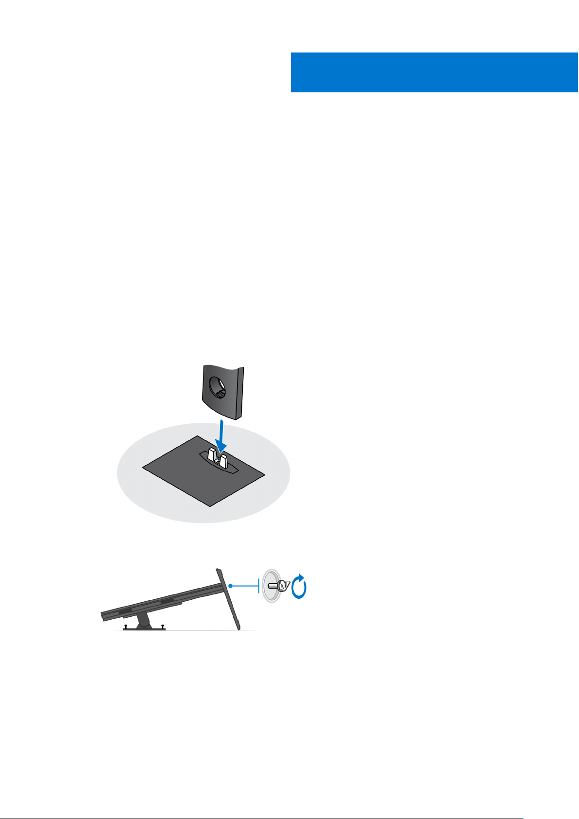
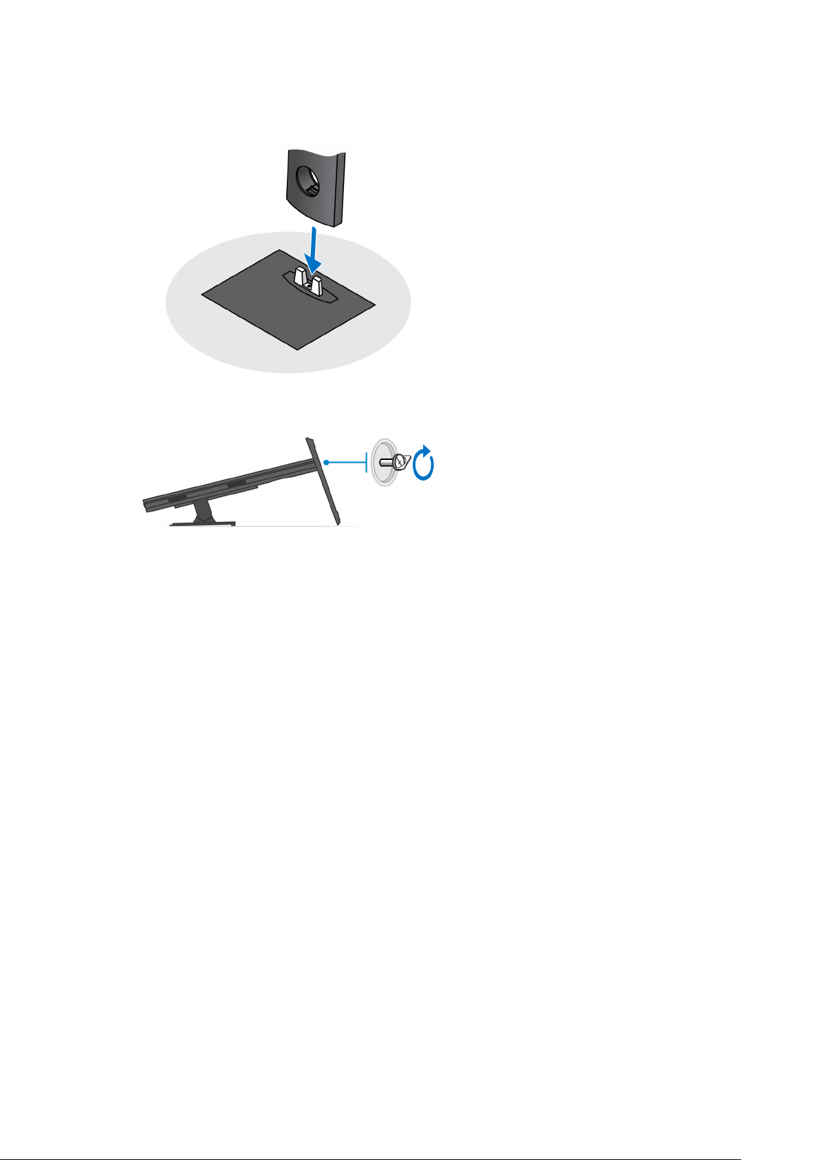
Installing the device on a fixed stand
1. Align and insert the slots on the fixed stand into the tab on the stand base.
2. Lift and tilt the stand base.
3. Tighten the captive screw to secure the stand to the base.
1
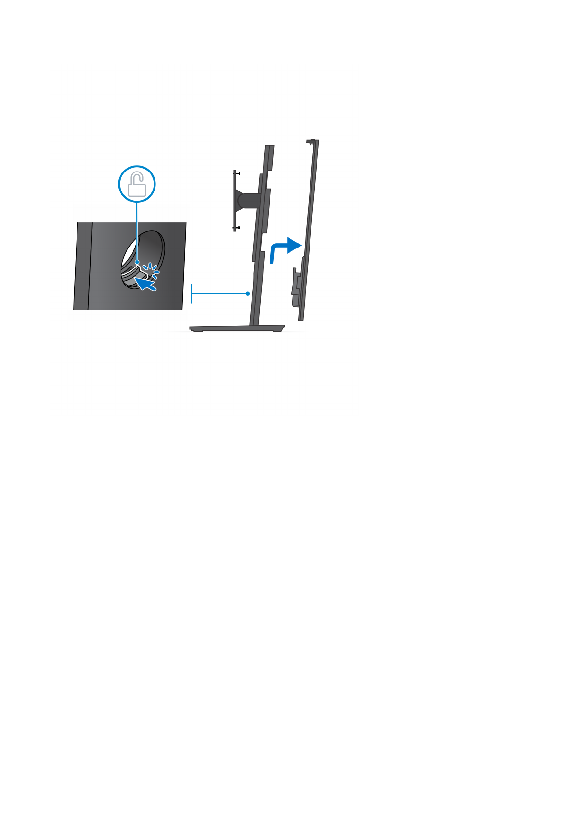
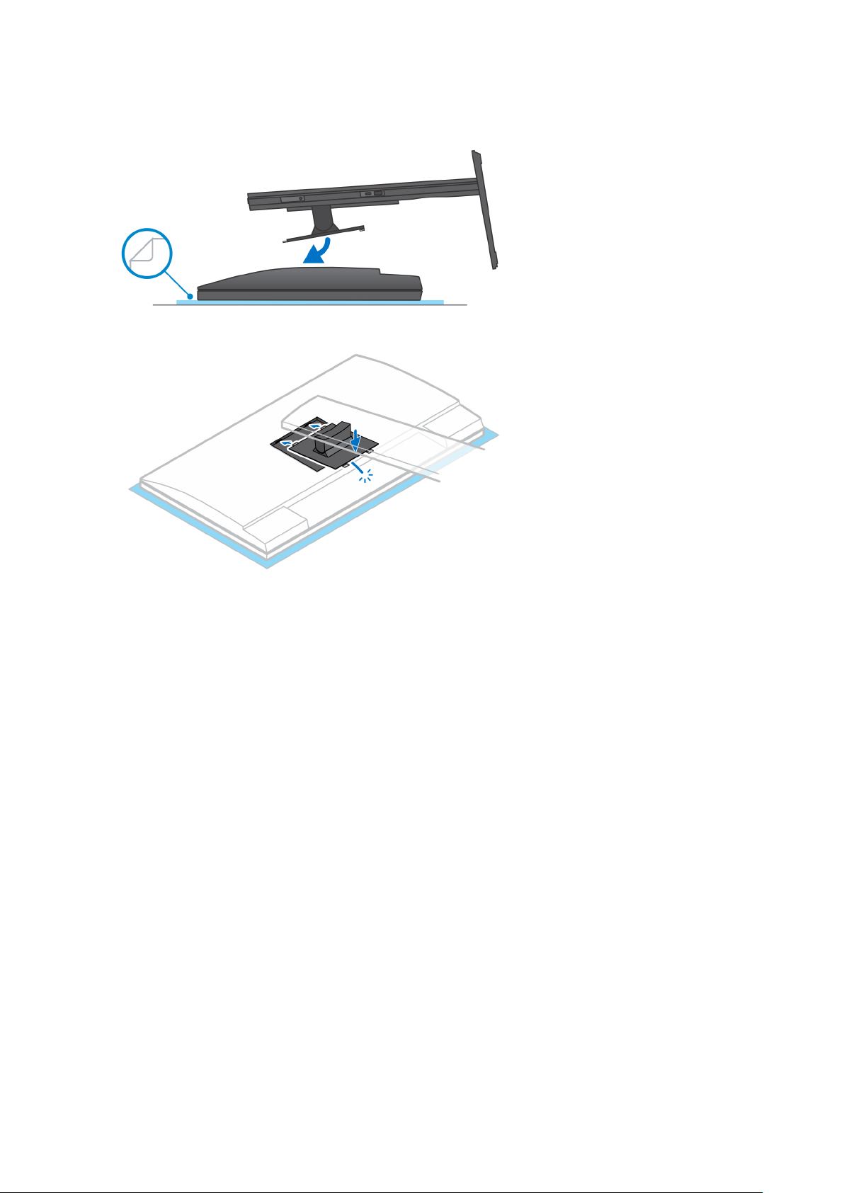
4. Slide the release latch on the stand, until you hear a click, to release the stand cover.
5. Slide and lift the cover to release it from the stand.
Set up your OptiPlex 7090 Ultra 5
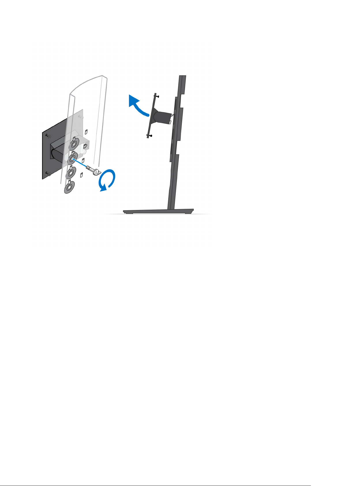
6. Remove the screw that secures the stand mounting bracket to the stand.
7. Lift the mounting bracket to release the hooks on the bracket from the slots on the stand.
6
Set up your OptiPlex 7090 Ultra
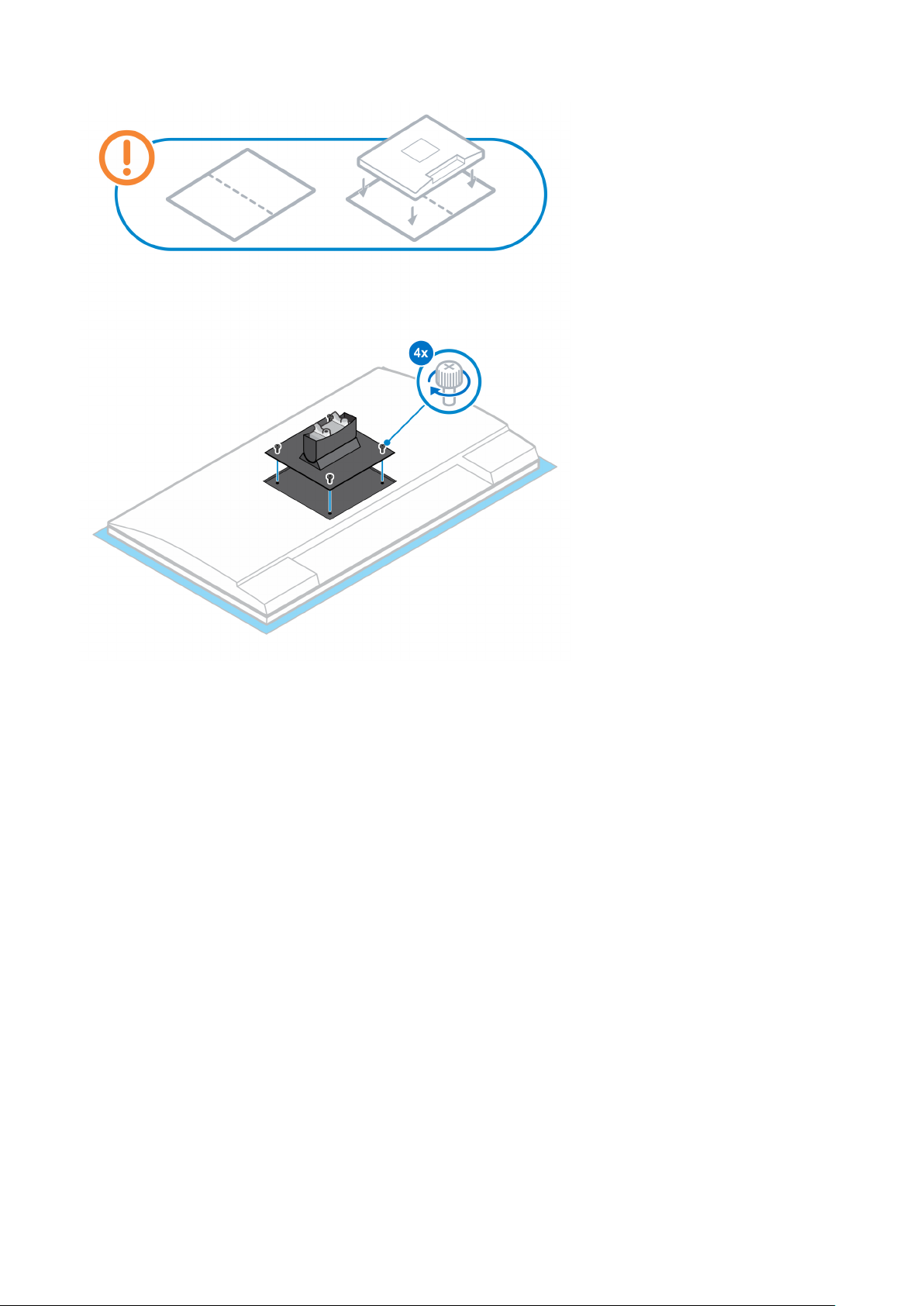
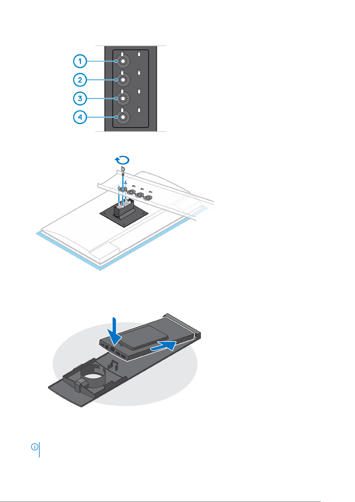
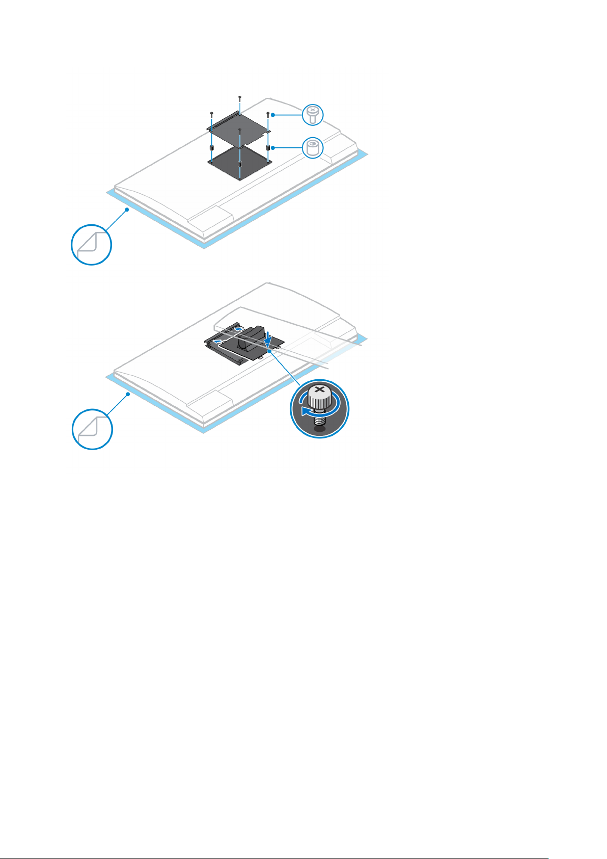
8. To avoid any damage to the monitor, ensure that you place the monitor on a protective sheet.
9. Align the screws on the mounting bracket with the screw holes on the monitor.
10. Tighten the four captive screws to secure the mounting bracket to the monitor.
Set up your OptiPlex 7090 Ultra
7
11. Select the height at which you want to mount the monitor and align the hooks on the mounting bracket with the slots on the
stand.
12. Replace the screw to secure the fixed stand to the monitor.
8
Set up your OptiPlex 7090 Ultra
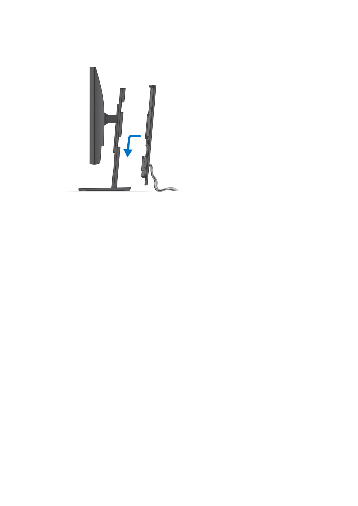
13. Align the vents on the device with the vents on the stand cover.
14. Lower the device in the stand until you hear a click.
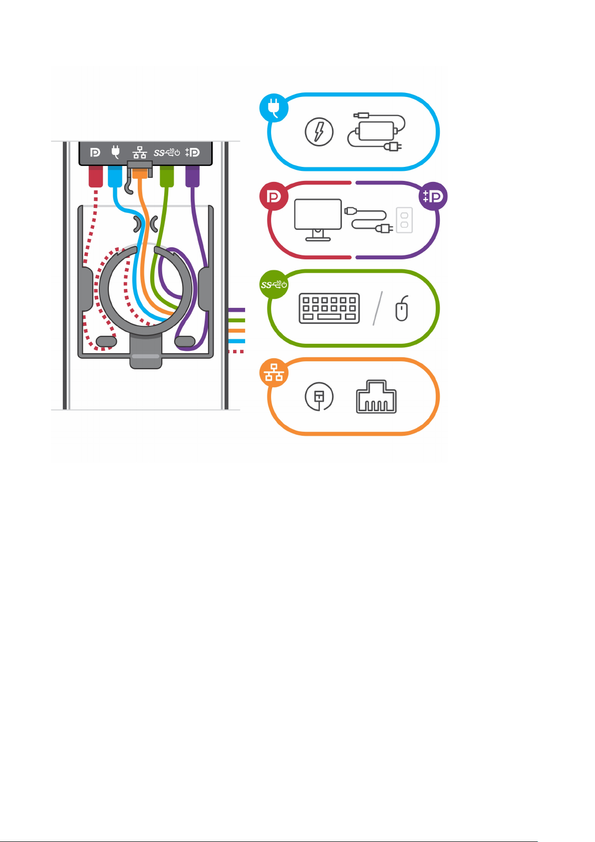
15. Connect the power, network, keyboard, mouse, and display cables to the device and to the power outlet.
To avoid any pinching or crimping of the cables while closing the stand cover, it is recommended that you route
NOTE:
the cables as indicated in the image.
Set up your OptiPlex 7090 Ultra 9

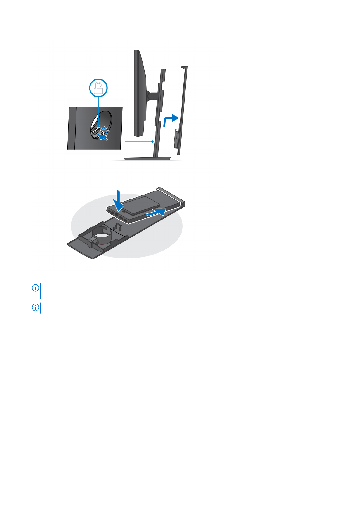
NOTE: All the cables and ports are used depending on the peripherals chosen and the configuration of the computer.
16. Slide the back cover, along with the device, into the stand until you hear a click.
10
Set up your OptiPlex 7090 Ultra
17. Lock the device and the stand cover.
Set up your OptiPlex 7090 Ultra
11

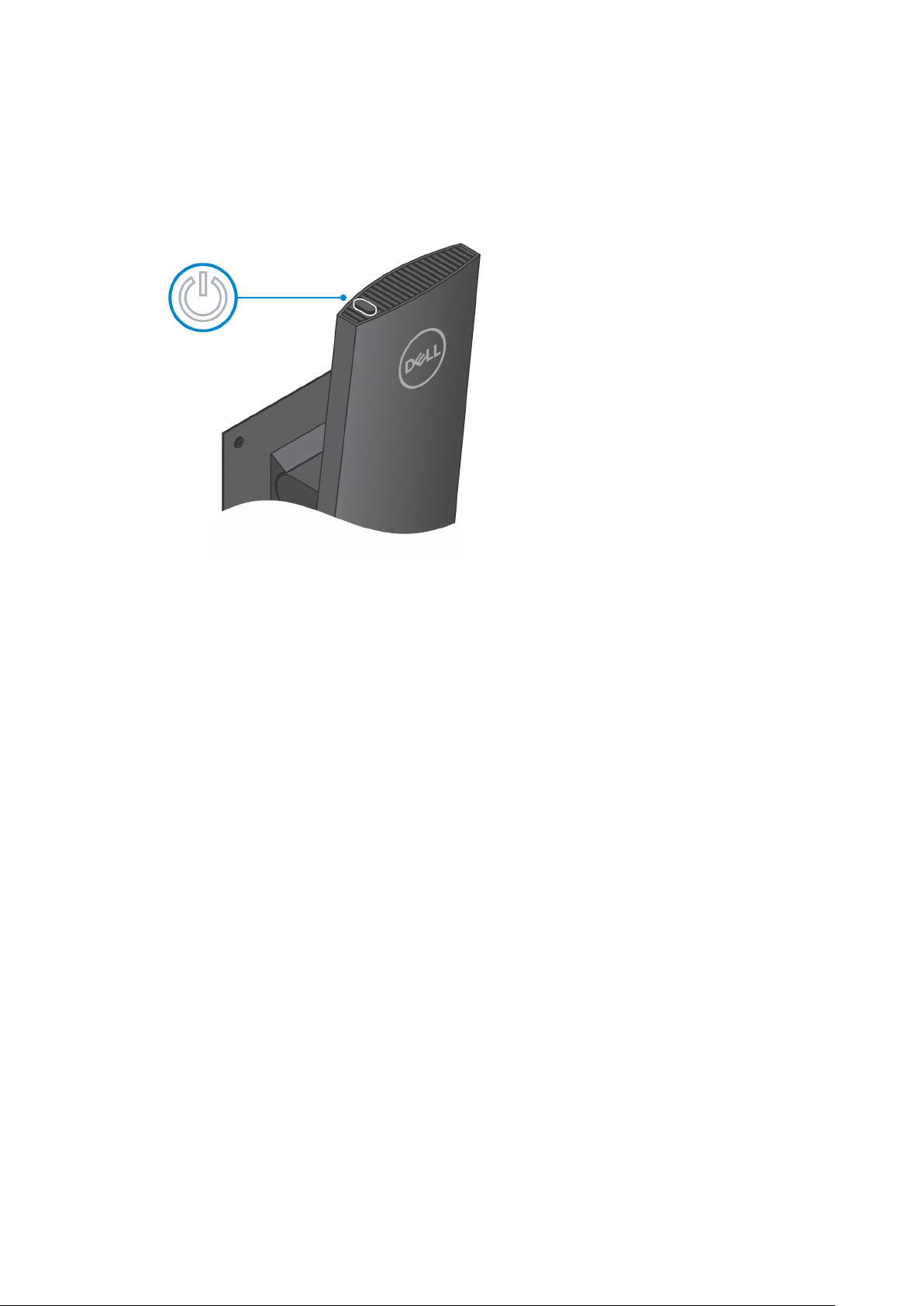
18. Press the power button to turn on the device.
12
Set up your OptiPlex 7090 Ultra
Set up your OptiPlex 7090 Ultra 13
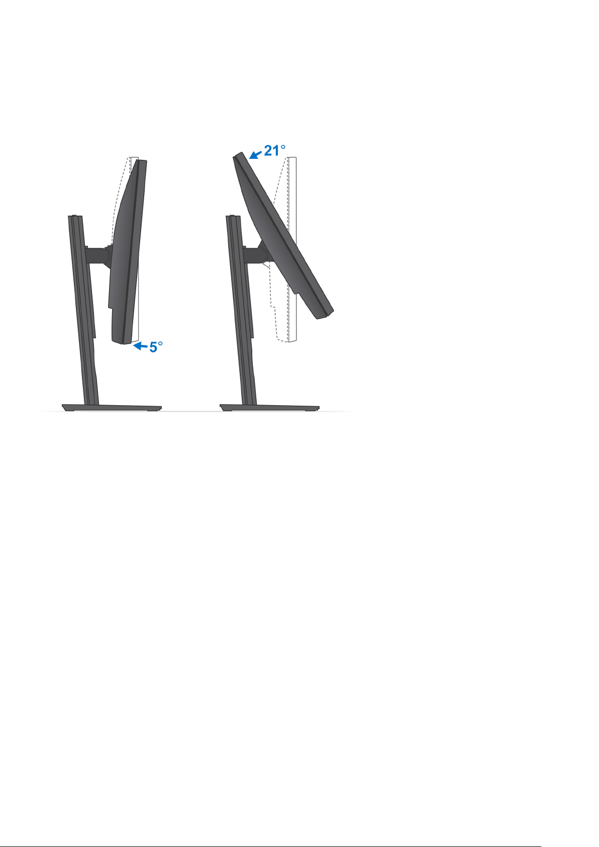
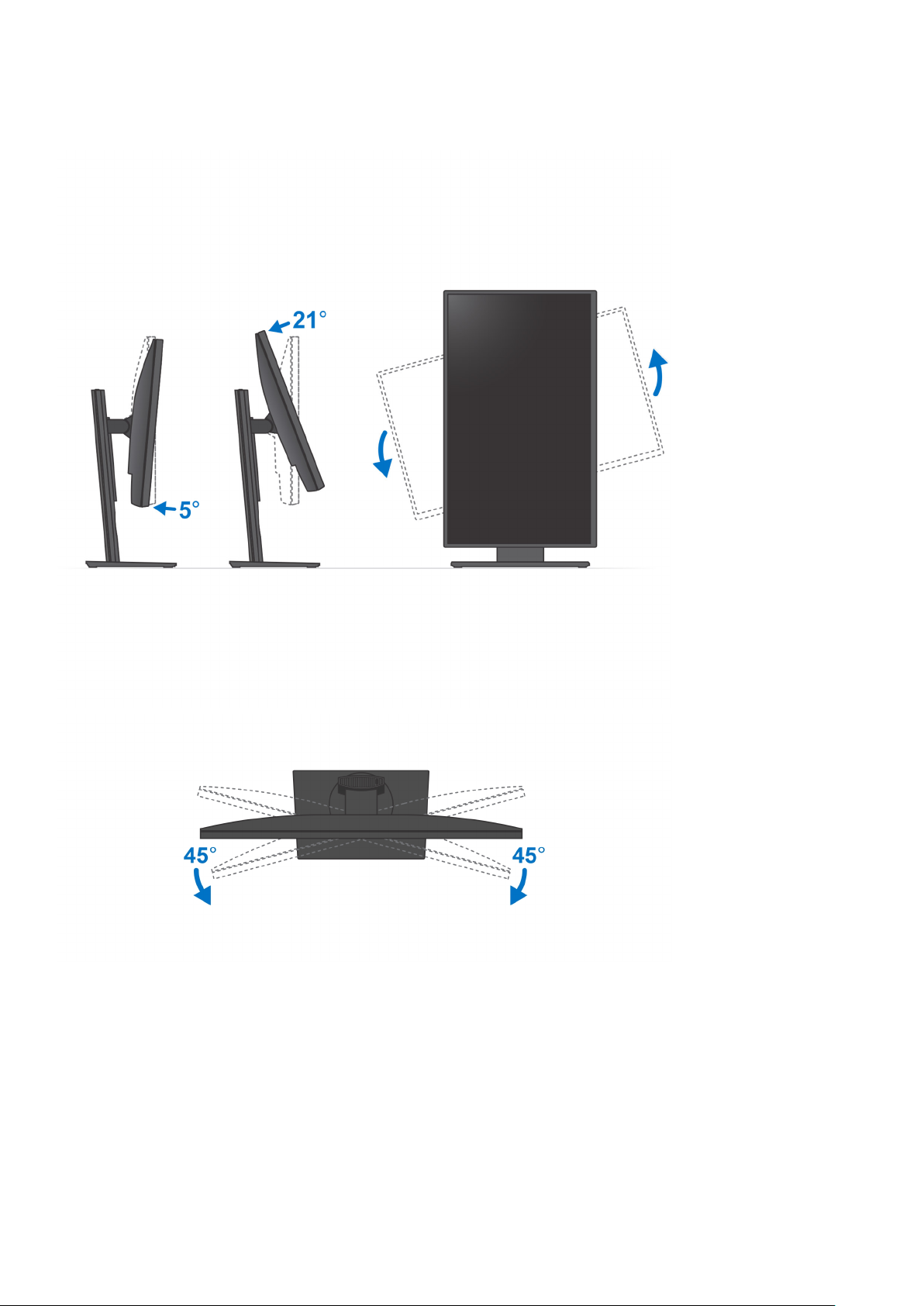
Monitor tilt angle
Installing the device on a Pro 1 height-adjustable stand
1. Align and insert the slots on the height-adjustable stand into the tab on the stand base.
2. Lift and tilt the stand base.
3. Tighten the captive screw to secure the stand to the base.
14
Set up your OptiPlex 7090 Ultra
4. To avoid any damage to the monitor, ensure that you place the monitor on a protective sheet.
5. For installing the height-adjustable stand to the monitor:
a. Align and insert the hooks on the mounting bracket on the stand into the slots on the monitor, until you hear a click.
Set up your OptiPlex 7090 Ultra
15
6. For installing QR to VESA bracket for E-Series monitor:
a. Align the screw holes on the QR to VESA bracket with the screw holes on the monitor.
b. Install the four screw spacers and the screws to secure the QR to VESA bracket to the monitor.
c. Align and insert the QR tabs on the stand into the slots on the QR to VESA bracket on the monitor.
d. Tighten the thumb screw to secure the stand to the QR to VESA bracket.
16
Set up your OptiPlex 7090 Ultra
7. To release the stand cover, slide the release latch until you hear a click.
8. Slide and lift the cover to release it from the stand.
9. Align the vents on the device with the vents on the stand cover.
10. Lower the device in the stand until you hear a click.
Set up your OptiPlex 7090 Ultra
17
11. Connect the power, network, keyboard, mouse, and display cables to the device and to the power outlet.
NOTE:
To avoid any pinching or crimping of the cables while closing the stand cover, it is recommended that you route
the cables as indicated in the image.
NOTE: All the cables and ports are used depending on the peripherals chosen and the configuration of the computer.
18 Set up your OptiPlex 7090 Ultra
12. Slide the back cover, along with the device, into the stand until you hear a click.
Set up your OptiPlex 7090 Ultra
19

13. Lock the device and the stand cover.
20
Set up your OptiPlex 7090 Ultra

14. Press the power button to turn on the device.
Set up your OptiPlex 7090 Ultra
21

22 Set up your OptiPlex 7090 Ultra
Stand tilt, pivot, and swivel images
Installing device on offset VESA mount
1. Align the screw holes on the device with the screw holes on the offset VESA mount.
2. Install the four screws to secure the device to the offset VESA mount.
Set up your OptiPlex 7090 Ultra
23
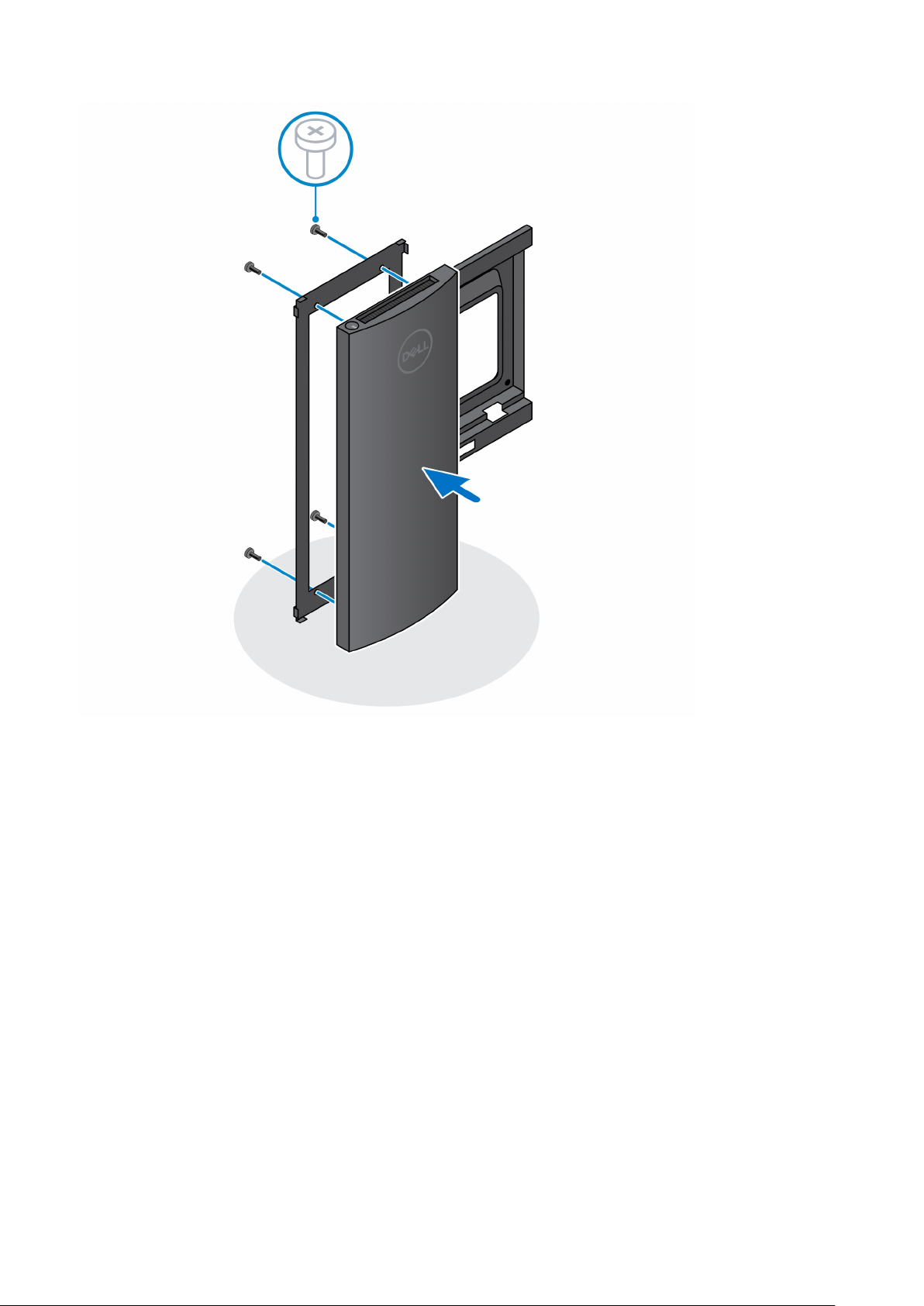
3. To avoid any damage to the monitor, ensure that you place the monitor on a protective sheet.
4. Align the screw holes on the offset VESA mount with the screw holes on the monitor.
5. Install the four screw spacers and the screws to secure the offset VESA mount to the monitor.
24
Set up your OptiPlex 7090 Ultra
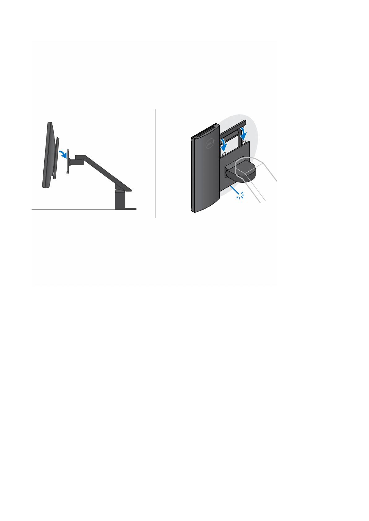
6. Insert the hooks on the mounting bracket of the monitor arm stand into the slots on the offset VESA mount on the monitor.
7. Lower the monitor on the monitor arm stand until you hear a click.
Set up your OptiPlex 7090 Ultra
25
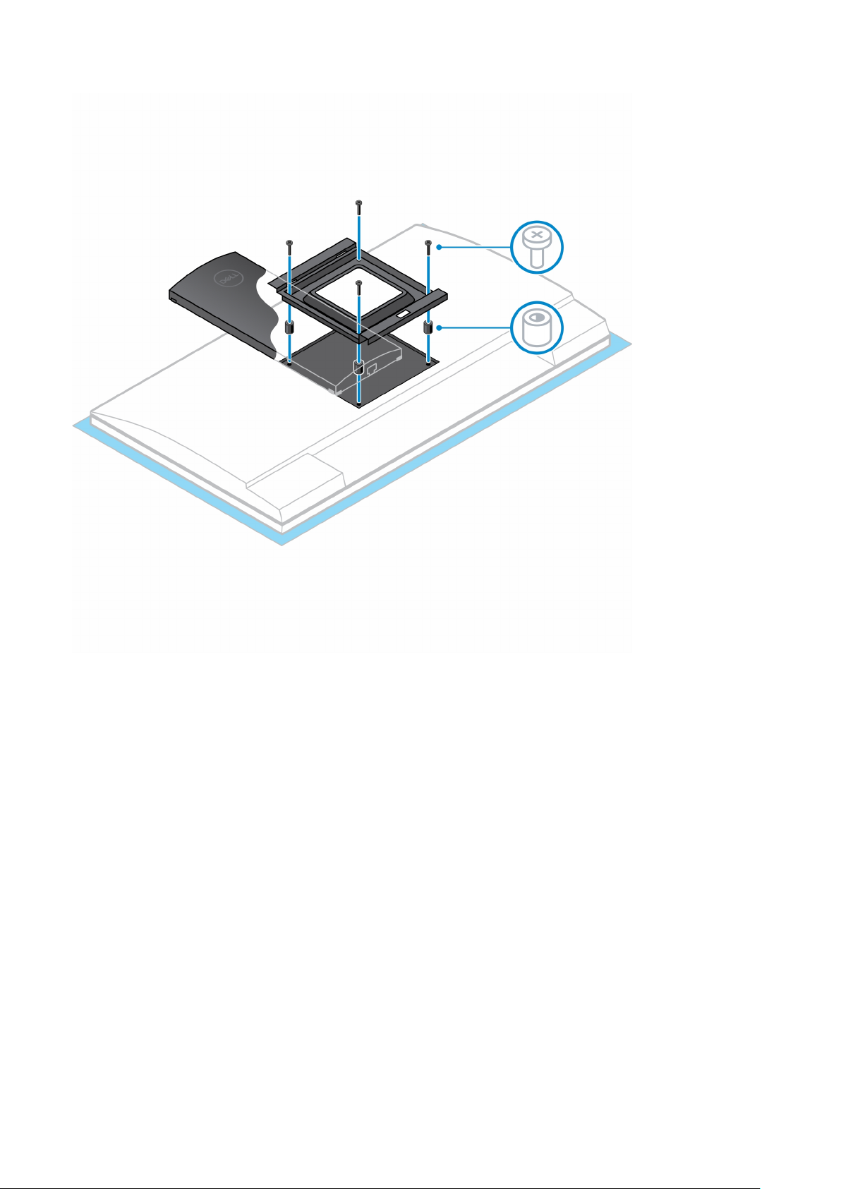
8. To install the offset VESA mount on a Dell E-Series monitor:
a. Align and install the four screws to secure the device to the offset VESA mount.
26
Set up your OptiPlex 7090 Ultra

b. Remove the VESA cover from the back of the monitor and secure the offset VESA mount along with the device to the
monitor.
Set up your OptiPlex 7090 Ultra
27
 Loading...