

Page 1

OptiPlex 7071 Tower
Service Manual
Regulatory Model: D28M
Regulatory Type: D28M001
Page 2

Notes, cautions, and warnings
NOTE: A NOTE indicates important information that helps you make better use of your product.
CAUTION: A CAUTION indicates either potential damage to hardware or loss of data and tells you how to avoid the
problem.
WARNING: A WARNING indicates a potential for property damage, personal injury, or death.
© 2019 - 2020 Dell Inc. or its subsidiaries. All rights reserved. Dell, EMC, and other trademarks are trademarks of Dell Inc. or its
subsidiaries. Other trademarks may be trademarks of their respective owners.
2020 - 03
Rev. A01
Page 3

Contents
1 Working on your computer............................................................................................................ 6
Safety instructions.................................................................................................................................................................6
Before working inside your computer........................................................................................................................... 6
Safety precautions...........................................................................................................................................................7
Electrostatic discharge—ESD protection.................................................................................................................... 7
ESD field service kit ........................................................................................................................................................8
Transporting sensitive components.............................................................................................................................. 9
After working inside your computer.............................................................................................................................. 9
2 Major components of your system................................................................................................10
3 Disassembly and reassembly........................................................................................................ 12
Recommended tools............................................................................................................................................................ 12
Screw list...............................................................................................................................................................................12
Left-side cover..................................................................................................................................................................... 13
Removing the left-side cover....................................................................................................................................... 13
Installing the left-side cover..........................................................................................................................................14
Front cover........................................................................................................................................................................... 16
Removing the front cover.............................................................................................................................................16
Installing the front cover............................................................................................................................................... 16
2.5-inch hard drive............................................................................................................................................................... 17
Removing the 2.5-inch hard drive................................................................................................................................17
Installing the 2.5-inch hard drive.................................................................................................................................. 18
2.5-inch hard drive bracket.................................................................................................................................................19
Removing the 2.5-inch hard drive bracket................................................................................................................. 19
Installing the 2.5-inch hard drive bracket...................................................................................................................20
3.5-inch hard drive............................................................................................................................................................... 21
Removing the 3.5-inch hard drive................................................................................................................................21
Installing the 3.5-inch hard drive................................................................................................................................. 22
3.5-inch hard drive bracket................................................................................................................................................24
Removing the 3.5-inch hard drive bracket.................................................................................................................24
Installing the 3.5-inch hard drive bracket................................................................................................................... 24
Slim optical-drive................................................................................................................................................................. 25
Removing the Optical Disk Drive................................................................................................................................. 25
Installing the Optical Disk Drive....................................................................................................................................26
Slim optical-drive bracket................................................................................................................................................... 27
Removing the slim ODD bracket..................................................................................................................................27
Installing the slim ODD bracket....................................................................................................................................28
Chassis fan........................................................................................................................................................................... 29
Removing the chassis fan.............................................................................................................................................29
Installing the chassis fan............................................................................................................................................... 30
Memory modules..................................................................................................................................................................31
Removing the memory modules...................................................................................................................................31
Installing the memory modules.....................................................................................................................................32
Contents 3
Page 4

Wireless card........................................................................................................................................................................33
Removing the wireless card......................................................................................................................................... 33
Installing the wireless card............................................................................................................................................34
Solid-state drive/Intel Optane...........................................................................................................................................35
Removing the 2230 solid-state drive/Intel Optane memory module..................................................................... 35
Installing the 2230 solid-state drive/Intel Optane memory module........................................................................36
Removing the 2280 solid-state drive/Intel Optane memory module......................................................................37
Installing the 2280 solid-state drive/Intel Optane memory module........................................................................37
Graphics card.......................................................................................................................................................................38
Removing the graphics card........................................................................................................................................ 38
Installing the graphics card...........................................................................................................................................39
Coin-cell battery.................................................................................................................................................................. 40
Removing the coin-cell battery....................................................................................................................................40
Installing the coin-cell battery.......................................................................................................................................41
Power-supply unit................................................................................................................................................................42
Removing the power-supply unit.................................................................................................................................42
Installing the power-supply unit................................................................................................................................... 44
Processor fan and heat-sink assembly............................................................................................................................. 47
Removing the processor fan and 95 W heat-sink assembly....................................................................................47
Installing the processor fan and 95 W heat-sink assembly...................................................................................... 48
Removing the processor fan and 65 W heat-sink assembly....................................................................................49
Installing the processor fan and 65 W heat-sink assembly...................................................................................... 49
Processor............................................................................................................................................................................. 50
Removing the processor...............................................................................................................................................50
Installing the processor..................................................................................................................................................51
VR heat sink......................................................................................................................................................................... 53
Removing the VR heat sink..........................................................................................................................................53
Installing the VR heat sink............................................................................................................................................ 53
Speaker.................................................................................................................................................................................54
Removing the speaker.................................................................................................................................................. 54
Installing the speaker.....................................................................................................................................................55
Power button.......................................................................................................................................................................56
Removing the power button........................................................................................................................................ 56
Installing the power button...........................................................................................................................................57
Intrusion switch................................................................................................................................................................... 58
Removing the intrusion switch.................................................................................................................................... 58
Installing the intrusion switch.......................................................................................................................................59
System board.......................................................................................................................................................................60
Removing the system board........................................................................................................................................ 60
Installing the system board...........................................................................................................................................64
4 System setup.............................................................................................................................69
Entering BIOS setup program............................................................................................................................................69
Boot menu............................................................................................................................................................................69
Navigation keys....................................................................................................................................................................69
Boot Sequence.................................................................................................................................................................... 70
System setup options......................................................................................................................................................... 70
General options.............................................................................................................................................................. 70
System information........................................................................................................................................................ 71
Video screen options..................................................................................................................................................... 72
4
Contents
Page 5

Security........................................................................................................................................................................... 73
Secure boot options...................................................................................................................................................... 74
Intel Software Guard Extensions options................................................................................................................... 75
Performance...................................................................................................................................................................75
Power management...................................................................................................................................................... 76
Post behavior................................................................................................................................................................. 76
Manageability..................................................................................................................................................................77
Virtualization support.....................................................................................................................................................77
Wireless options............................................................................................................................................................. 78
Maintenance...................................................................................................................................................................78
System logs.................................................................................................................................................................... 78
Advanced configuration................................................................................................................................................ 78
System and setup password.............................................................................................................................................. 79
Assigning a system setup password............................................................................................................................79
Deleting or changing an existing system setup password........................................................................................79
Clearing CMOS settings............................................................................................................................................... 80
Clearing BIOS (System Setup) and System passwords...........................................................................................80
Updating the BIOS in Windows ........................................................................................................................................ 80
Updating BIOS on systems with BitLocker enabled.................................................................................................. 81
Updating your system BIOS using a USB flash drive.................................................................................................81
Updating the Dell BIOS in Linux and Ubuntu environments.....................................................................................82
Flashing the BIOS from the F12 One-Time boot menu.............................................................................................82
5 Troubleshooting......................................................................................................................... 88
Enhanced Pre-Boot System Assessment (ePSA) diagnostics......................................................................................88
Running the ePSA diagnostics.....................................................................................................................................88
Diagnostics........................................................................................................................................................................... 88
Diagnostic error messages................................................................................................................................................. 90
System error messages...................................................................................................................................................... 93
Recovering the operating system..................................................................................................................................... 93
Enabling Intel Optane memory...........................................................................................................................................94
Disabling Intel Optane memory..........................................................................................................................................94
Flea power release...............................................................................................................................................................94
WiFi power cycle................................................................................................................................................................. 95
6 Getting help...............................................................................................................................96
Contacting Dell.................................................................................................................................................................... 96
Contents
5
Page 6

Working on your computer
Safety instructions
Prerequisites
Use the following safety guidelines to protect your computer from potential damage and to ensure your personal safety. Unless otherwise
noted, each procedure included in this document assumes that the following conditions exist:
• You have read the safety information that shipped with your computer.
• A component can be replaced or, if purchased separately, installed by performing the removal procedure in reverse order.
About this task
NOTE: Disconnect all power sources before opening the computer cover or panels. After you finish working inside the
computer, replace all covers, panels, and screws before connecting to the power source.
WARNING: Before working inside your computer, read the safety information that shipped with your computer. For
additional safety best practices information, see the Regulatory Compliance Homepage
CAUTION: Many repairs may only be done by a certified service technician. You should only perform troubleshooting and
simple repairs as authorized in your product documentation, or as directed by the online or telephone service and
support team. Damage due to servicing that is not authorized by Dell is not covered by your warranty. Read and follow
the safety instructions that came with the product.
1
CAUTION: To avoid electrostatic discharge, ground yourself by using a wrist grounding strap or by periodically touching
an unpainted metal surface at the same time as touching a connector on the back of the computer.
CAUTION: Handle components and cards with care. Do not touch the components or contacts on a card. Hold a card by
its edges or by its metal mounting bracket. Hold a component such as a processor by its edges, not by its pins.
CAUTION: When you disconnect a cable, pull on its connector or on its pull-tab, not on the cable itself. Some cables
have connectors with locking tabs; if you are disconnecting this type of cable, press in on the locking tabs before you
disconnect the cable. As you pull connectors apart, keep them evenly aligned to avoid bending any connector pins. Also,
before you connect a cable, ensure that both connectors are correctly oriented and aligned.
NOTE: The color of your computer and certain components may appear differently than shown in this document.
CAUTION: System will shut down if side covers are removed while the system is running. The system will not power on
if the side cover is removed.
CAUTION: System will shut down if side covers are removed while the system is running. The system will not power on
if the side cover is removed.
CAUTION: System will shut down if side covers are removed while the system is running. The system will not power on
if the side cover is removed.
Before working inside your computer
About this task
To avoid damaging your computer, perform the following steps before you begin working inside the computer.
6 Working on your computer
Page 7

Steps
1. Ensure that you follow the Safety Instruction.
2. Ensure that your work surface is flat and clean to prevent the computer cover from being scratched.
3. Turn off your computer.
4. Disconnect all network cables from the computer.
CAUTION: To disconnect a network cable, first unplug the cable from your computer and then unplug the cable from
the network device.
5. Disconnect your computer and all attached devices from their electrical outlets.
6. Press and hold the power button while the computer is unplugged to ground the system board.
NOTE: To avoid electrostatic discharge, ground yourself by using a wrist grounding strap or by periodically touching
an unpainted metal surface at the same time as touching a connector on the back of the computer.
Safety precautions
The safety precautions chapter details the primary steps to be taken before performing any disassembly instructions.
Observe the following safety precautions before you perform any installation or break/fix procedures involving disassembly or reassembly:
• Turn off the system and all attached peripherals.
• Disconnect the system and all attached peripherals from AC power.
• Disconnect all network cables, telephone, and telecommunications lines from the system.
• Use an ESD field service kit when working inside any tabletnotebookdesktop to avoid electrostatic discharge (ESD) damage.
• After removing any system component, carefully place the removed component on an anti-static mat.
• Wear shoes with non-conductive rubber soles to reduce the chance of getting electrocuted.
Standby power
Dell products with standby power must be unplugged before you open the case. Systems that incorporate standby power are essentially
powered while turned off. The internal power enables the system to be remotely turned on (wake on LAN) and suspended into a sleep
mode and has other advanced power management features.
Unplugging, pressing and holding the power button for 15 seconds should discharge residual power in the system board. Remove the
battery from tablets.notebooks.
Bonding
Bonding is a method for connecting two or more grounding conductors to the same electrical potential. This is done through the use of a
field service electrostatic discharge (ESD) kit. When connecting a bonding wire, ensure that it is connected to bare metal and never to a
painted or non-metal surface. The wrist strap should be secure and in full contact with your skin, and ensure that you remove all jewelry
such as watches, bracelets, or rings prior to bonding yourself and the equipment.
Electrostatic discharge—ESD protection
ESD is a major concern when you handle electronic components, especially sensitive components such as expansion cards, processors,
memory DIMMs, and system boards. Very slight charges can damage circuits in ways that may not be obvious, such as intermittent
problems or a shortened product life span. As the industry pushes for lower power requirements and increased density, ESD protection is
an increasing concern.
Due to the increased density of semiconductors used in recent Dell products, the sensitivity to static damage is now higher than in
previous Dell products. For this reason, some previously approved methods of handling parts are no longer applicable.
Two recognized types of ESD damage are catastrophic and intermittent failures.
• Catastrophic – Catastrophic failures represent approximately 20 percent of ESD-related failures. The damage causes an immediate
and complete loss of device functionality. An example of catastrophic failure is a memory DIMM that has received a static shock and
immediately generates a "No POST/No Video" symptom with a beep code emitted for missing or nonfunctional memory.
• Intermittent – Intermittent failures represent approximately 80 percent of ESD-related failures. The high rate of intermittent failures
means that most of the time when damage occurs, it is not immediately recognizable. The DIMM receives a static shock, but the
tracing is merely weakened and does not immediately produce outward symptoms related to the damage. The weakened trace may
take weeks or months to melt, and in the meantime may cause degradation of memory integrity, intermittent memory errors, etc.
The more difficult type of damage to recognize and troubleshoot is the intermittent (also called latent or "walking wounded") failure.
Working on your computer
7
Page 8

Perform the following steps to prevent ESD damage:
• Use a wired ESD wrist strap that is properly grounded. The use of wireless anti-static straps is no longer allowed; they do not provide
adequate protection. Touching the chassis before handling parts does not ensure adequate ESD protection on parts with increased
sensitivity to ESD damage.
• Handle all static-sensitive components in a static-safe area. If possible, use anti-static floor pads and workbench pads.
• When unpacking a static-sensitive component from its shipping carton, do not remove the component from the anti-static packing
material until you are ready to install the component. Before unwrapping the anti-static packaging, ensure that you discharge static
electricity from your body.
• Before transporting a static-sensitive component, place it in an anti-static container or packaging.
ESD field service kit
The unmonitored Field Service kit is the most commonly used service kit. Each Field Service kit includes three main components: antistatic mat, wrist strap, and bonding wire.
Components of an ESD field service kit
The components of an ESD field service kit are:
• Anti-Static Mat – The anti-static mat is dissipative and parts can be placed on it during service procedures. When using an antistatic mat, your wrist strap should be snug and the bonding wire should be connected to the mat and to any bare metal on the system
being worked on. Once deployed properly, service parts can be removed from the ESD bag and placed directly on the mat. ESDsensitive items are safe in your hand, on the ESD mat, in the system, or inside a bag.
• Wrist Strap and Bonding Wire – The wrist strap and bonding wire can be either directly connected between your wrist and bare
metal on the hardware if the ESD mat is not required, or connected to the anti-static mat to protect hardware that is temporarily
placed on the mat. The physical connection of the wrist strap and bonding wire between your skin, the ESD mat, and the hardware is
known as bonding. Use only Field Service kits with a wrist strap, mat, and bonding wire. Never use wireless wrist straps. Always be
aware that the internal wires of a wrist strap are prone to damage from normal wear and tear, and must be checked regularly with a
wrist strap tester in order to avoid accidental ESD hardware damage. It is recommended to test the wrist strap and bonding wire at
least once per week.
• ESD Wrist Strap Tester – The wires inside of an ESD strap are prone to damage over time. When using an unmonitored kit, it is a
best practice to regularly test the strap prior to each service call, and at a minimum, test once per week. A wrist strap tester is the
best method for doing this test. If you do not have your own wrist strap tester, check with your regional office to find out if they have
one. To perform the test, plug the wrist-strap's bonding-wire into the tester while it is strapped to your wrist and push the button to
test. A green LED is lit if the test is successful; a red LED is lit and an alarm sounds if the test fails.
• Insulator Elements – It is critical to keep ESD sensitive devices, such as plastic heat sink casings, away from internal parts that are
insulators and often highly charged.
• Working Environment – Before deploying the ESD Field Service kit, assess the situation at the customer location. For example,
deploying the kit for a server environment is different than for a desktop or portable environment. Servers are typically installed in a
rack within a data center; desktops or portables are typically placed on office desks or cubicles. Always look for a large open flat work
area that is free of clutter and large enough to deploy the ESD kit with additional space to accommodate the type of system that is
being repaired. The workspace should also be free of insulators that can cause an ESD event. On the work area, insulators such as
Styrofoam and other plastics should always be moved at least 12 inches or 30 centimeters away from sensitive parts before physically
handling any hardware components
• ESD Packaging – All ESD-sensitive devices must be shipped and received in static-safe packaging. Metal, static-shielded bags are
preferred. However, you should always return the damaged part using the same ESD bag and packaging that the new part arrived in.
The ESD bag should be folded over and taped shut and all the same foam packing material should be used in the original box that the
new part arrived in. ESD-sensitive devices should be removed from packaging only at an ESD-protected work surface, and parts
should never be placed on top of the ESD bag because only the inside of the bag is shielded. Always place parts in your hand, on the
ESD mat, in the system, or inside an anti-static bag.
• Transporting Sensitive Components – When transporting ESD sensitive components such as replacement parts or parts to be
returned to Dell, it is critical to place these parts in anti-static bags for safe transport.
ESD protection summary
It is recommended that all field service technicians use the traditional wired ESD grounding wrist strap and protective anti-static mat at all
times when servicing Dell products. In addition, it is critical that technicians keep sensitive parts separate from all insulator parts while
performing service and that they use anti-static bags for transporting sensitive components.
8
Working on your computer
Page 9

Transporting sensitive components
When transporting ESD sensitive components such as replacement parts or parts to be returned to Dell, it is critical to place these parts in
anti-static bags for safe transport.
Lifting equipment
Adhere to the following guidelines when lifting heavy weight equipment:
CAUTION: Do not lift greater than 50 pounds. Always obtain additional resources or use a mechanical lifting device.
1. Get a firm balanced footing. Keep your feet apart for a stable base, and point your toes out.
2. Tighten stomach muscles. Abdominal muscles support your spine when you lift, offsetting the force of the load.
3. Lift with your legs, not your back.
4. Keep the load close. The closer it is to your spine, the less force it exerts on your back.
5. Keep your back upright, whether lifting or setting down the load. Do not add the weight of your body to the load. Avoid twisting your
body and back.
6. Follow the same techniques in reverse to set the load down.
After working inside your computer
About this task
After you complete any replacement procedure, ensure that you connect any external devices, cards, and cables before turning on your
computer.
Steps
1. Connect any telephone or network cables to your computer.
CAUTION:
computer.
2. Connect your computer and all attached devices to their electrical outlets.
3. Turn on your computer.
4. If required, verify that the computer works correctly by running ePSA diagnostics.
To connect a network cable, first plug the cable into the network device and then plug it into the
Working on your computer
9
Page 10
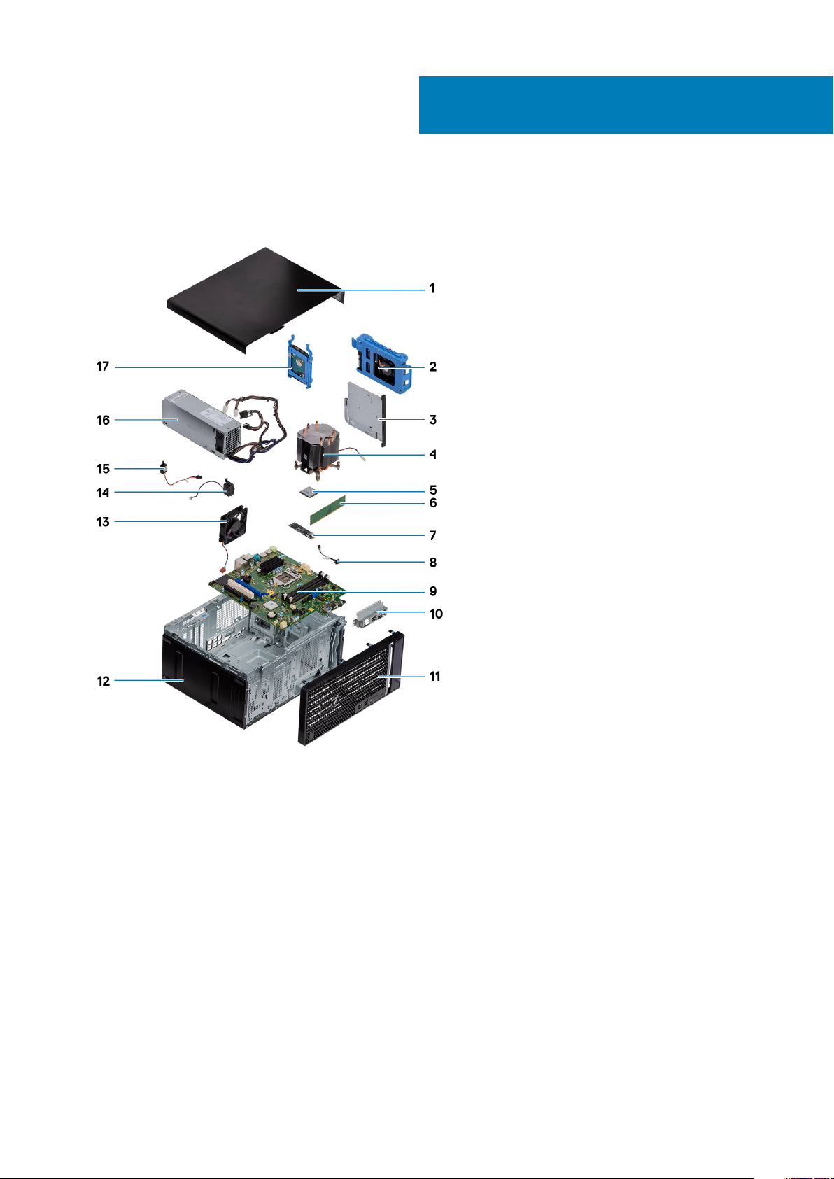
2
Major components of your system
1. Left-side cover
2. 3.5-inch hard drive
3. Slim optical-drive
4. Processor fan and heat-sink assembly
5. Processor
6. Memory module
7. Solid-state drive/Intel Optane
8. Power button
9. System board
10. Front I/O port bracket
11. Front cover
12. Chassis
13. Chassis fan
14. Speaker
15. Intrusion switch
16. Power-supply unit
17. 2.5-inch hard drive
10 Major components of your system
Page 11

NOTE: Dell provides a list of components and their part numbers for the original system configuration purchased. These
parts are available according to warranty coverages purchased by the customer. Contact your Dell sales representative
for purchase options.
Major components of your system 11
Page 12
Disassembly and reassembly
Recommended tools
The procedures in this document require the following tools:
• Phillips #0 screwdriver
• Phillips #1 screwdriver
• Philips #2 screwdriver
• Plastic scribe
• Hex screwdriver
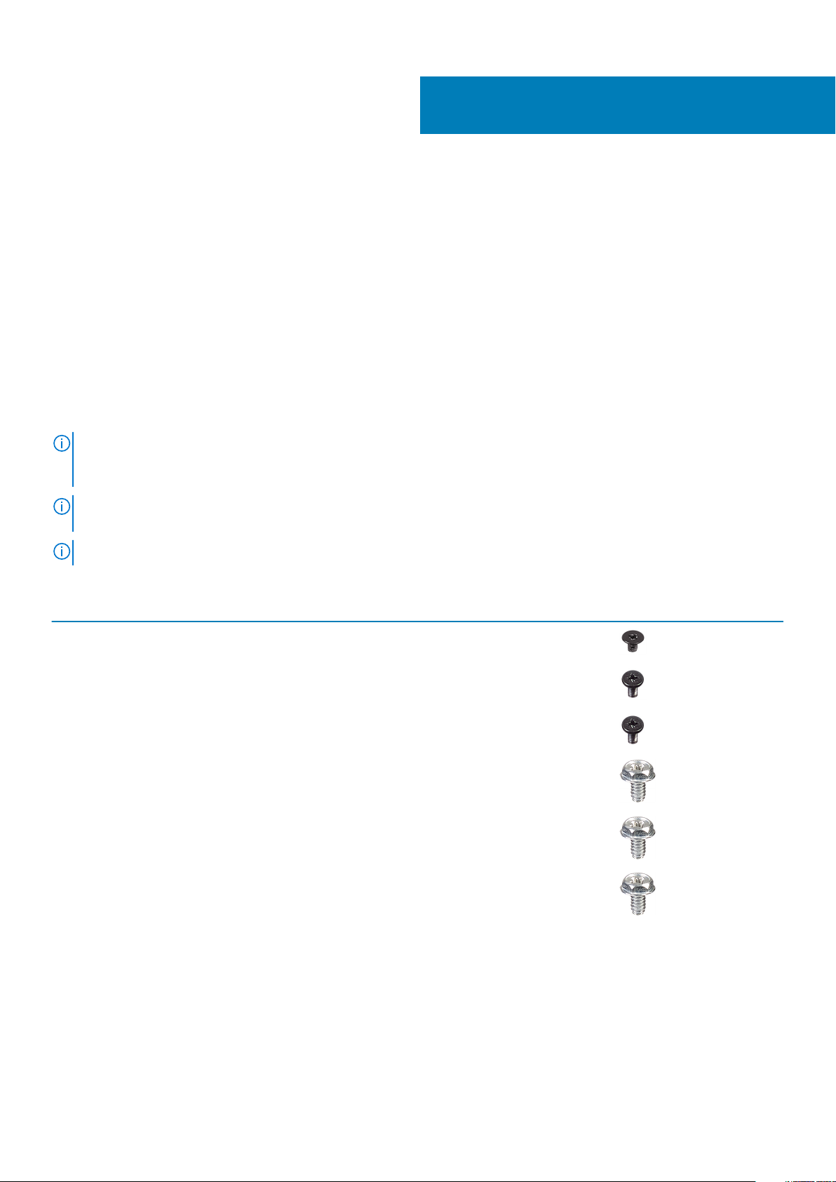
Screw list
NOTE: When removing screws from a component, it is recommended to note the screw type, the quantity of screws,
and then place them in a screw storage box. This is to ensure that the correct number of screws and correct screw type
is restored when the component is replaced.
NOTE: Some computers have magnetic surfaces. Ensure that the screws are not left attached to such surface when
replacing a component.
3
NOTE: Screw color may vary with the configuration ordered.
Table 1. Screw list
Component Secured to Screw type Quantity Screw image
Wireless card System board M2x3 1
Solid-state drive System board M2x4 1
Intel Optane memory
module
Power-supply unit Chassis #6-32 3
Ports bezel Chassis #6-32 1
System board Chassis #6-32 8
Processor fan and heatsink assembly
VR heat sink System board Captive screw 2
System board M2x4 1
System board Captive screw 4
12 Disassembly and reassembly
Page 13
Left-side cover
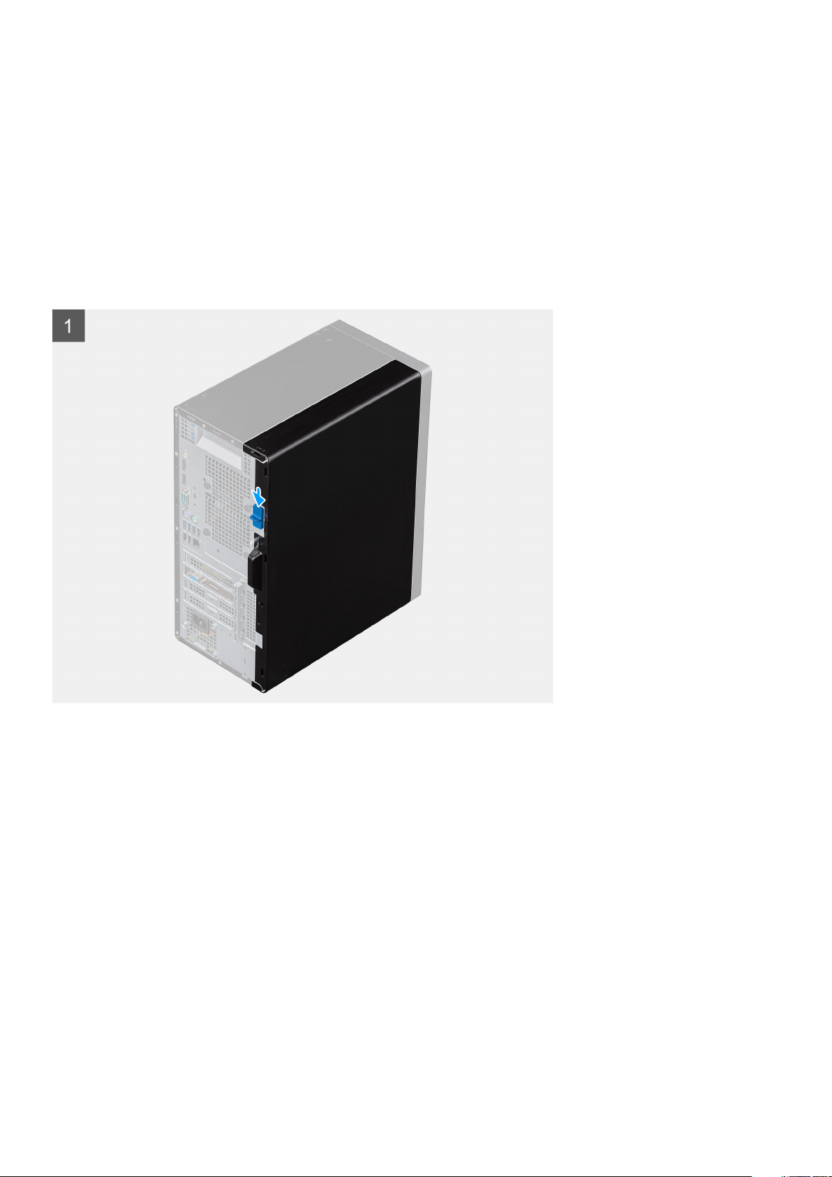
Removing the left-side cover
Prerequisites
1. Follow the procedure in Before working inside your computer.
About this task
The following images indicate the location of the left-side cover and provides a visual representation of the removal procedure.
Disassembly and reassembly 13
Page 14
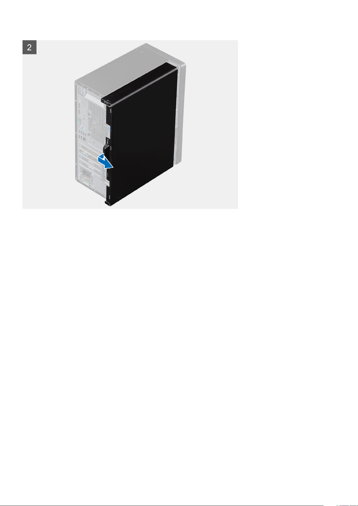
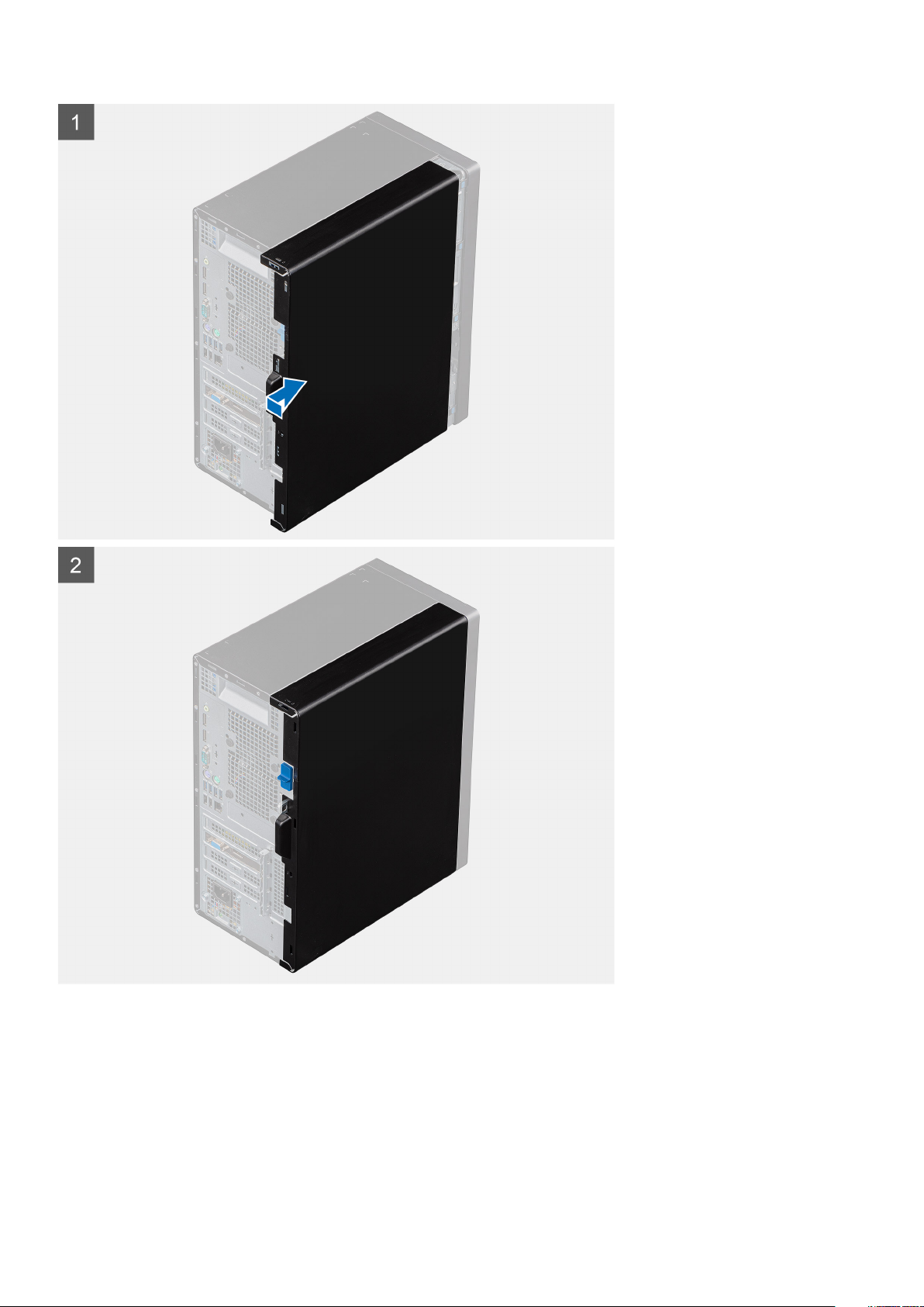
Steps
1. Push the release latch down to unlock the side cover.
2. Using the tab on the left-side cover, slide and lift the left-side cover off the chassis.
Installing the left-side cover
Prerequisites
If you are replacing a component, remove the existing component before performing the installation procedure.
About this task
The following images indicate the location of the left-side cover and provides a visual representation of the installation procedure.
14
Disassembly and reassembly
Page 15
Steps
1. Align the tabs on the left-side cover with the slots on the chassis.
2. Slide it towards the front of the computer until the release latch locks the side cover.
Next steps
1. Follow the procedure in After working inside your computer.
Disassembly and reassembly
15
Page 16
Front cover
Removing the front cover
Prerequisites
1. Follow the procedure in Before working inside your computer.
2. Remove the left-side cover.
About this task
The following images indicate the location of the front cover and provide a visual representation of the removal procedure.
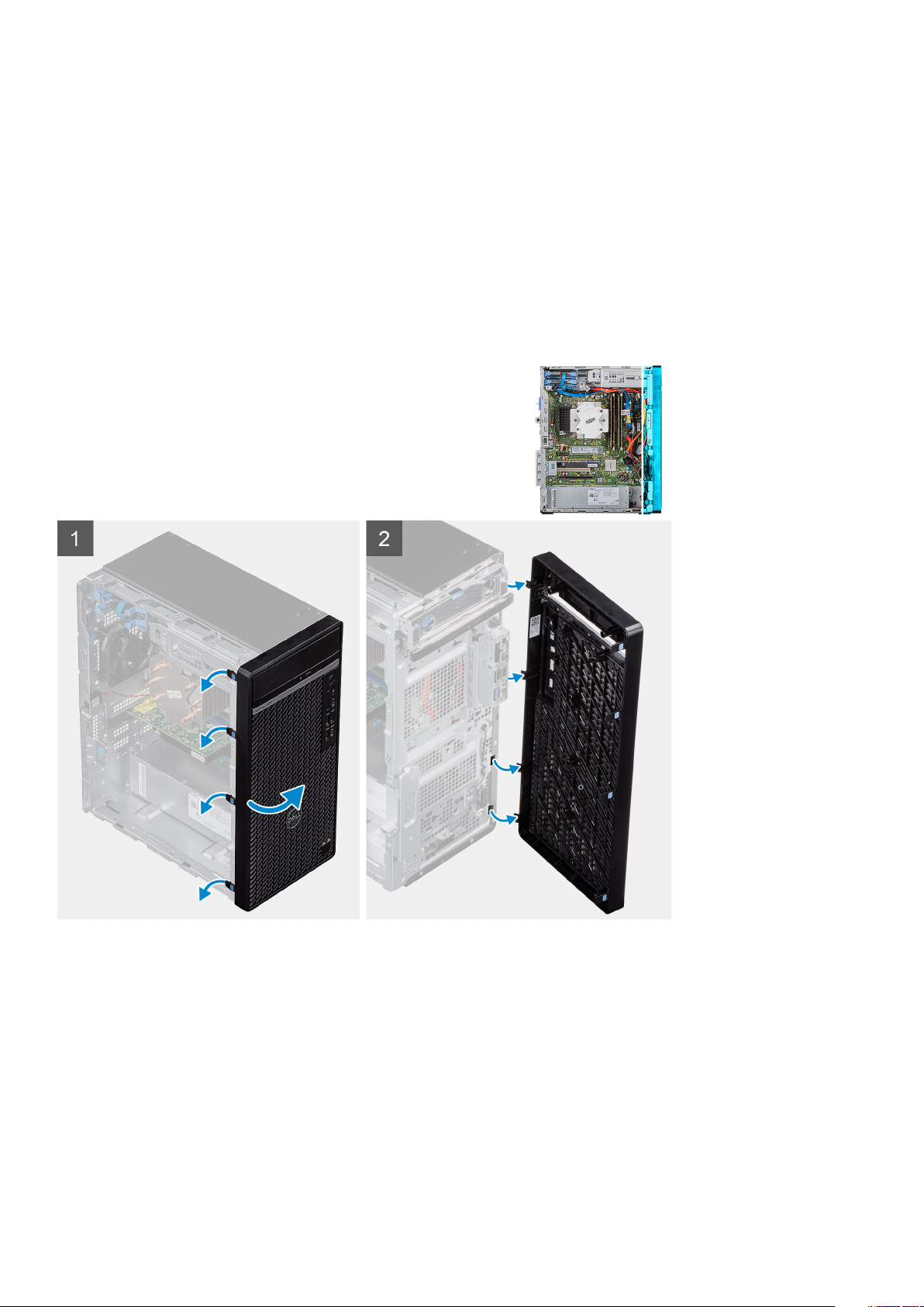
Steps
1. Place the computer in an upright position.
2. Gently pry and release the front-cover tabs sequentially from the top.
3. Move the front cover outward from the chassis.
Installing the front cover
Prerequisites
If you are replacing a component, remove the existing component before performing the installation procedure.
16
Disassembly and reassembly
Page 17
About this task
The following images indicate the location of the front cover and provide a visual representation of the installation procedure.
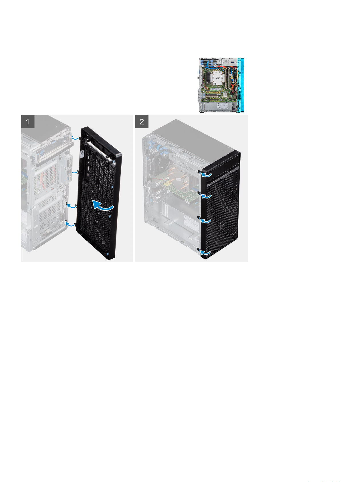
Steps
1. Place the computer in an upright position.
2. Align the front-cover tabs with the slots on the chassis.
3. Move the front cover towards the chassis and snap it into place.
Next steps
1. Install the left-side cover.
2. Follow the procedure in After working inside your computer.
2.5-inch hard drive
Removing the 2.5-inch hard drive
Prerequisites
1. Follow the procedure in Before working inside your computer.
2. Remove the left-side cover.
Disassembly and reassembly
17
Page 18
About this task
The following images indicate the location of the 2.5-inch hard drive assembly and provides a visual representation of the removal
procedure.
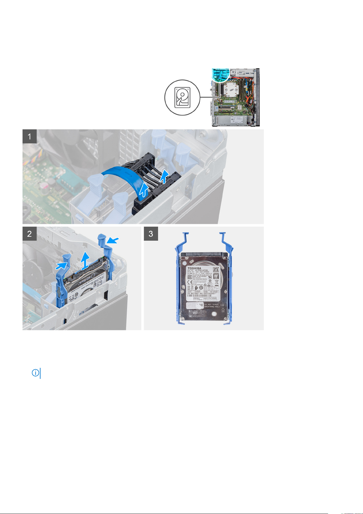
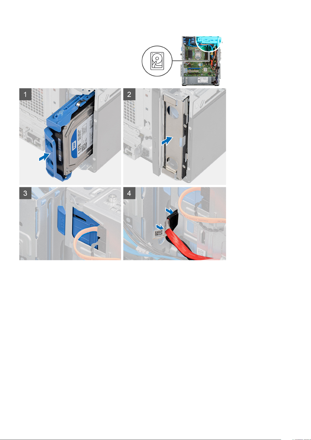
Steps
1. Disconnect the data and power cables from the hard drive.
2. Press the release tabs on the hard-drive bracket and slide the hard-drive assembly out of the hard-drive cage.
NOTE: Note the orientation or the SATA connector marking on the hard drive so that you can replace it correctly.
Installing the 2.5-inch hard drive
Prerequisites
If you are replacing a component, remove the existing component before performing the installation procedure.
About this task
The following images indicate the location of the 2.5-inch hard drive and provides a visual representation of the installation procedure.
18
Disassembly and reassembly
Page 19
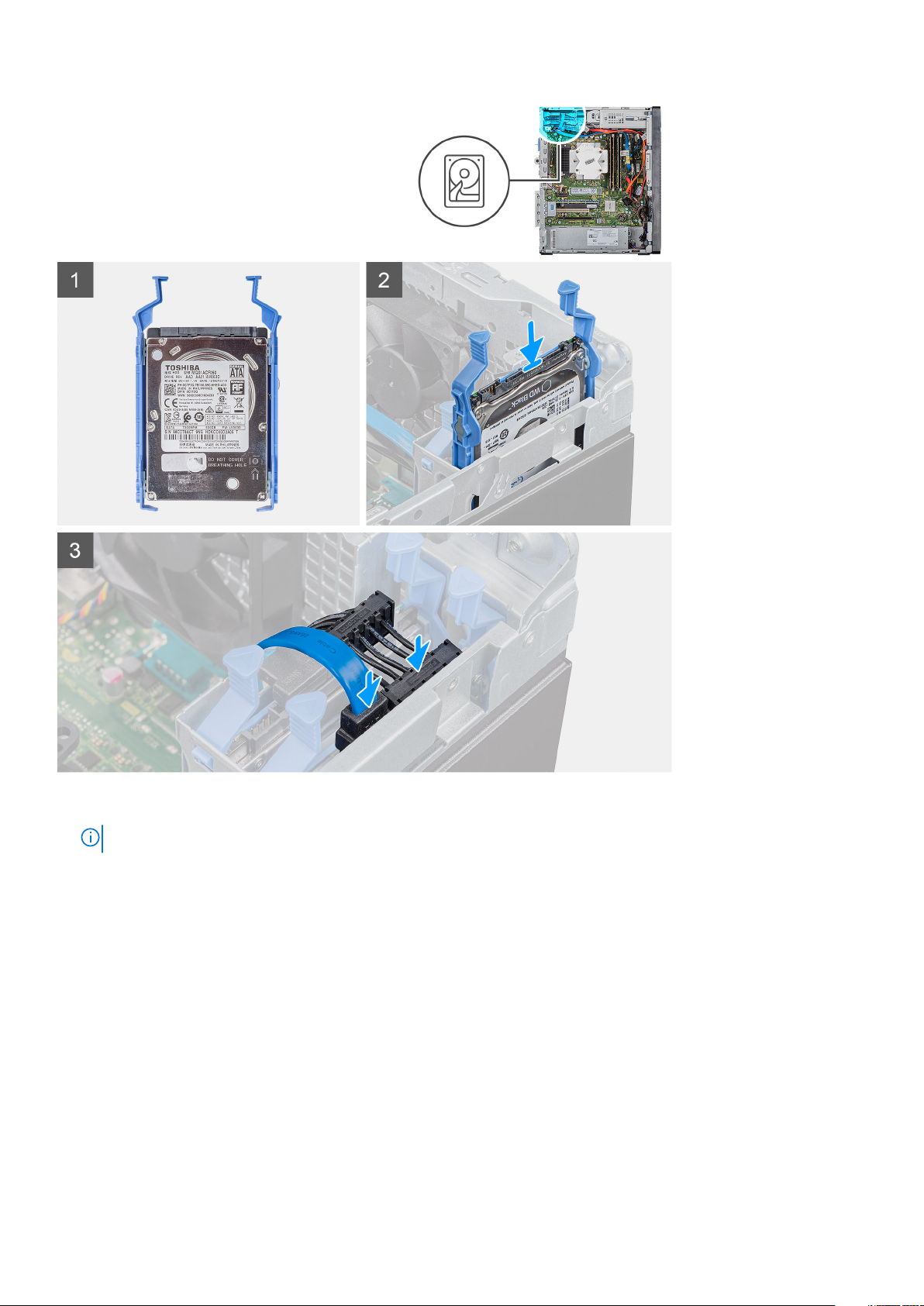
Steps
1.
2. Connect the data cable and power cable to the hard drive.
Next steps
1. Install the left-side cover.
2. Follow the procedure in After working inside your computer.
NOTE: Note the orientation or the SATA connector marking on the hard drive so that you can replace it correctly.
Slide the hard-drive assembly into the hard-drive cage until it snaps into place.
2.5-inch hard drive bracket
Removing the 2.5-inch hard drive bracket
Prerequisites
1. Follow the procedure in Before working inside your computer.
2. Remove the left-side cover.
Disassembly and reassembly
19
Page 20
3. Remove the 2.5-inch hard drive assembly.
About this task
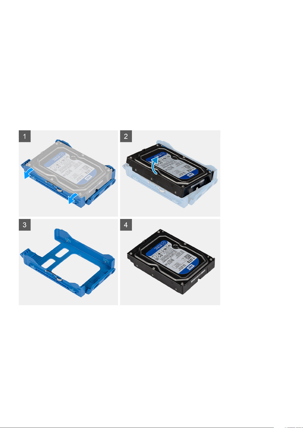
The following images indicate the location of the 2.5-inch hard drive bracket and provides a visual representation of the removal
procedure.
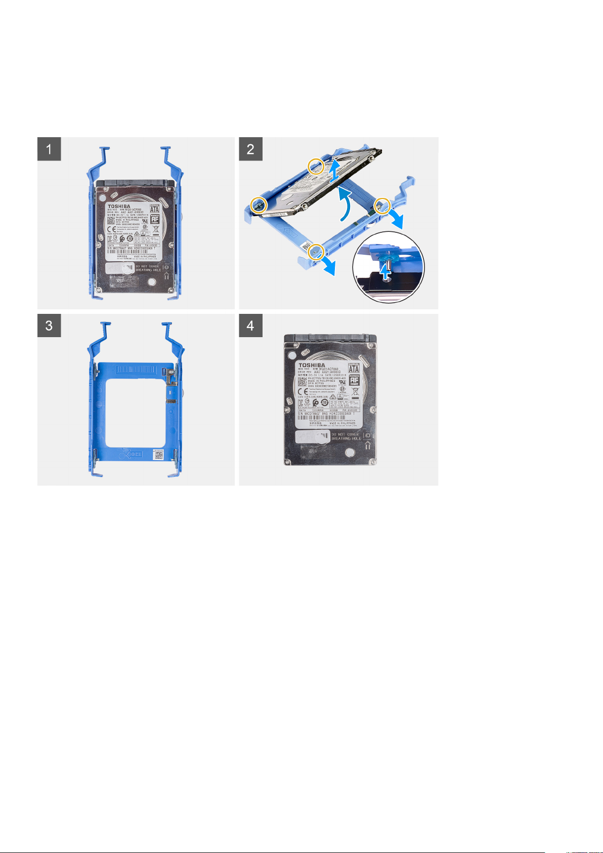
Steps
1. Pry the hard-drive bracket to release the tabs on the assembly from the slots on the hard drive.
2. Lift and remove the hard drive off the hard-drive bracket.
Installing the 2.5-inch hard drive bracket
Prerequisites
If you are replacing a component, remove the existing component before performing the installation procedure.
About this task
The following images indicate the location of the 2.5-inch hard drive bracket and provides a visual representation of the installation
procedure.
20
Disassembly and reassembly
Page 21
Steps
1. Place the hard drive into the hard-drive bracket and align the tabs on the bracket with the slots on the hard drive.
2. Snap the hard drive into the hard-drive bracket.
Next steps
1. Install the 2.5-inch hard drive assembly.
2. Install the left-side cover.
3. Follow the procedure in After working inside your computer.
3.5-inch hard drive
Removing the 3.5-inch hard drive
Prerequisites
1. Follow the procedure in Before working inside your computer.
2. Remove the left-side cover.
About this task
The following images indicate the location of the 3.5-inch hard drive assembly and provides a visual representation of the removal
procedure.
Disassembly and reassembly
21
Page 22
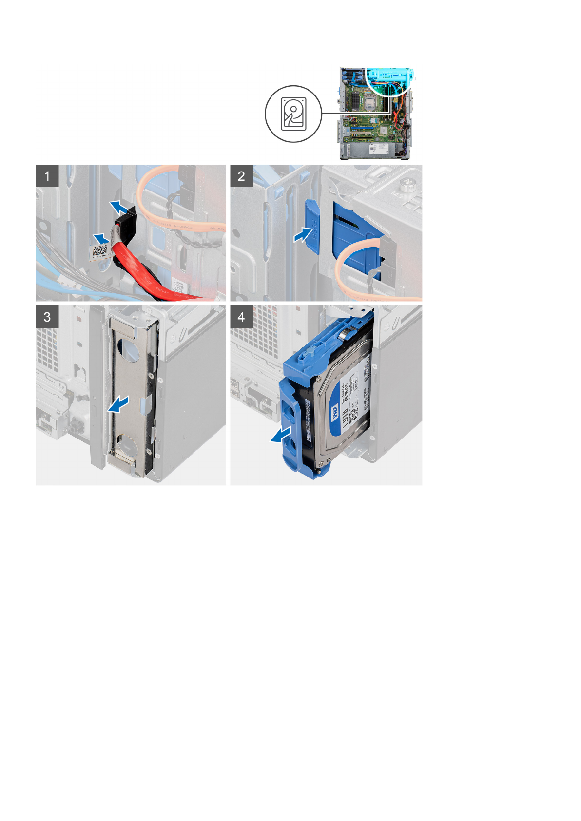
Steps
1. Lay the computer on the right side.
2. Disconnect the data and power cables from the hard drive.
3. Push the securing tab to release the hard drive bracket from the chassis.
4. Remove the EMI shied from the front-side of the chassis.
5. Slide the hard-drive assembly away from the chassis.
Installing the 3.5-inch hard drive
Prerequisites
If you are replacing a component, remove the existing component before performing the installation procedure.
About this task
The following images indicate the location of the 3.5-inch hard drive assembly and provides a visual representation of the installation
procedure.
22
Disassembly and reassembly
Page 23
Steps
1. Slide and insert the hard-drive assembly into the hard drive cage.
2. Replace the EMI shield on the chassis.
3. Align the hard-drive assembly with the tabs on the chassis.
4. Route the power cable and data cable through the routing guides on the hard-drive assembly and connect the cables to the hard
drive.
Next steps
1. Install the left-side cover.
2. Follow the procedure in After working inside your computer.
Disassembly and reassembly
23
Page 24
3.5-inch hard drive bracket
Removing the 3.5-inch hard drive bracket
Prerequisites
1. Follow the procedure in Before working inside your computer.
2. Remove the left-side cover.
3. Remove the 3.5-inch hard drive assembly.
About this task
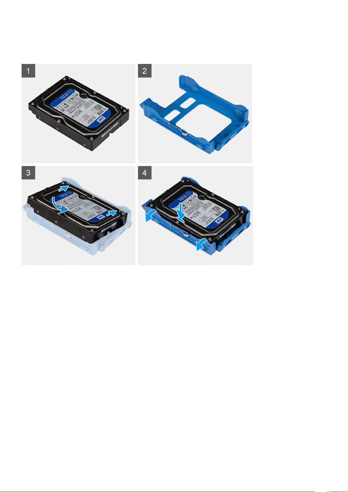
The following images indicate the location of the 3.5-inch hard drive bracket and provides a visual representation of the removal
procedure.
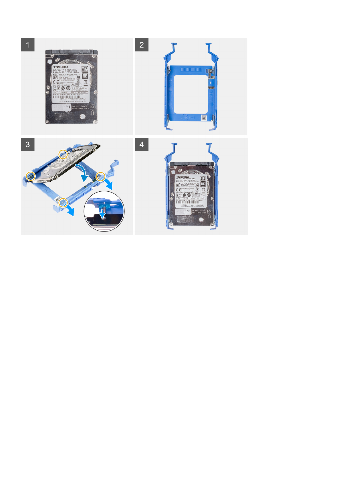
Steps
1. Pry the hard-drive bracket to release the tabs on the assembly from the slots on the hard drive.
2. Lift and remove the hard drive off the hard-drive bracket.
Installing the 3.5-inch hard drive bracket
Prerequisites
If you are replacing a component, remove the existing component before performing the installation procedure.
24
Disassembly and reassembly
Page 25
About this task
The following images indicate the location of the 3.5-inch hard drive bracket and provides a visual representation of the installation
procedure.
Steps
1. Place the hard drive into the hard-drive bracket and align the tabs on the bracket with the slots on the hard drive.
2. Snap the hard drive into the hard-drive bracket.
Next steps
1. Install the 3.5-inch hard drive assembly.
2. Install the left-side cover.
3. Follow the procedure in After working inside your computer.
Slim optical-drive
Removing the Optical Disk Drive
Prerequisites
1. Follow the procedure in Before working inside your computer.
2. Remove the left-side cover.
About this task
The following images indicate the location of the ODD and provides a visual representation of the removal procedure.
Disassembly and reassembly
25
Page 26
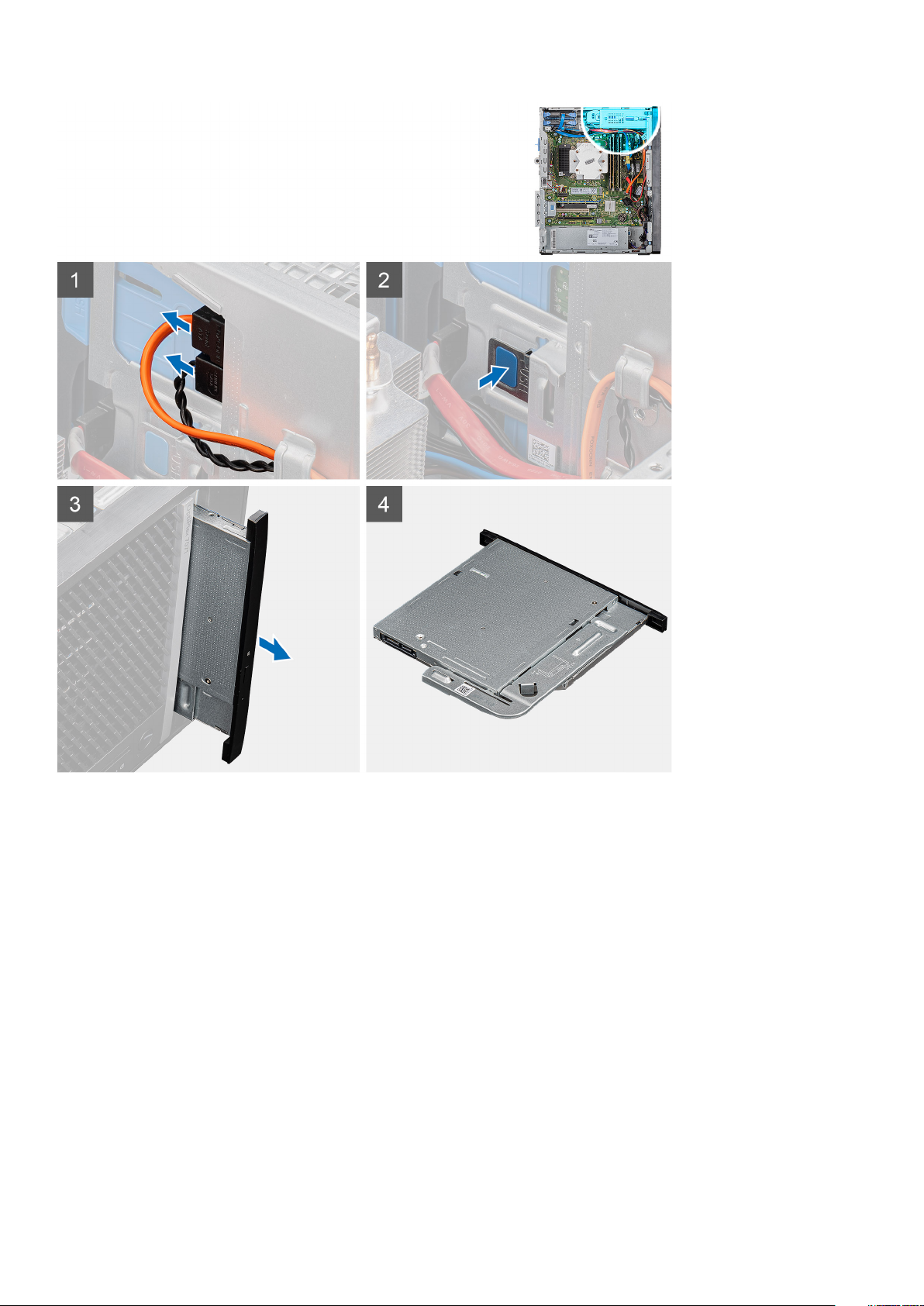
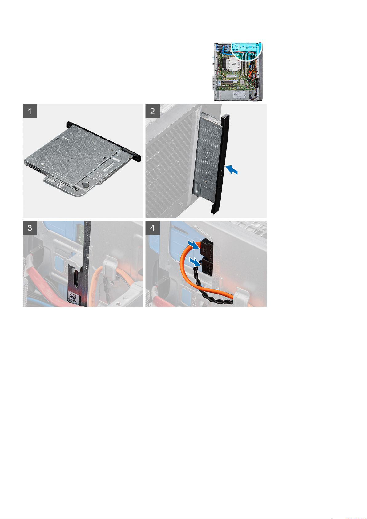
Steps
1. Lay the computer on the right side.
2. Disconnect the data and power cables from the ODD.
3. Push the securing tab to release the ODD from the chassis.
4. Slide and remove the ODD from the ODD slot.
Installing the Optical Disk Drive
Prerequisites
If you are replacing a component, remove the existing component before performing the installation procedure.
About this task
The following images indicate the location of the Optical Disk Drive and provide a visual representation of the installation procedure.
26
Disassembly and reassembly
Page 27
Steps
1. Insert the ODD assembly into the ODD slot.
2. Slide the ODD assembly until it snaps into place.
3. Route the power cable and data cable through the routing guides and connect the cables to the ODD.
Next steps
1. Install the left-side cover.
2. Follow the procedure in After working inside your computer.
Slim optical-drive bracket
Removing the slim ODD bracket
Prerequisites
1. Follow the procedure in Before working inside your computer.
2. Remove the left-side cover.
Disassembly and reassembly
27
Page 28
3. Remove the slim ODD assembly.
About this task
The following images indicate the location of the slim ODD bracket and provides a visual representation of the removal procedure.
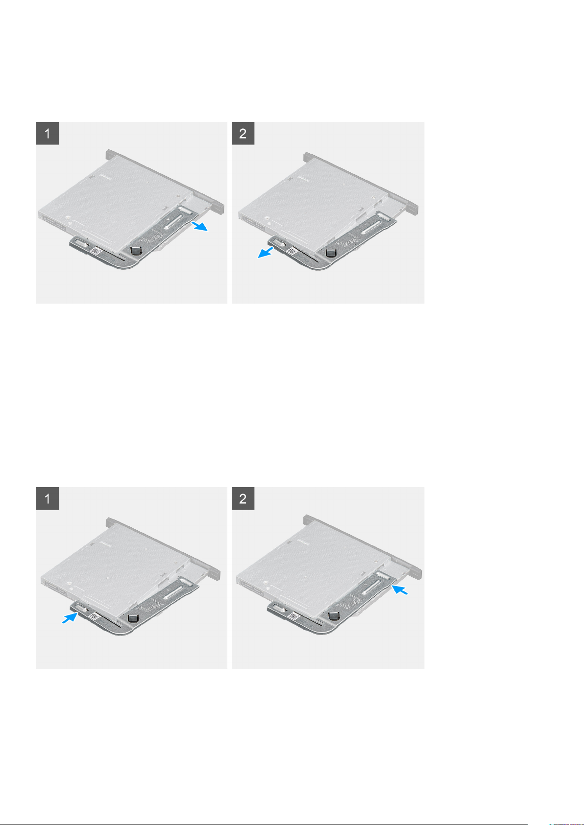
Steps
1. Pry the ODD bracket to release from the slots on the ODD.
2. Remove the ODD bracket off the ODD
Installing the slim ODD bracket
Prerequisites
If you are replacing a component, remove the existing component before performing the installation procedure.
About this task
The following images indicate the location of the slim ODD bracket and provides a visual representation of the installation procedure.
Steps
1. Align and place the ODD bracket on the ODD slots.
2. Snap the ODD bracket into the ODD.
28
Disassembly and reassembly
Page 29
Next steps
1. Install the slim ODD assembly.
2. Install the left-side cover.
3. Follow the procedure in After working inside your computer.
Chassis fan
Removing the chassis fan
Prerequisites
1. Follow the procedure in Before working inside your computer.
2. Remove the left-side cover.
About this task
The following images indicate the location of the chassis fan and provides a visual representation of the removal procedure.
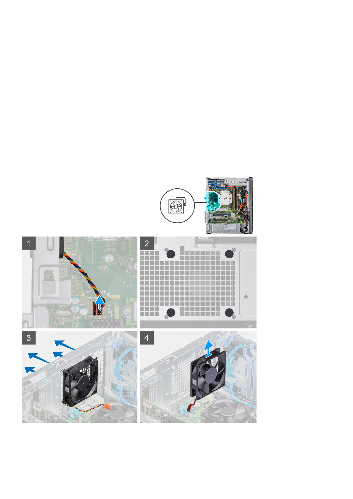
Steps
1. Lay the computer on the right side.
Disassembly and reassembly
29
Page 30

2. Disconnect the fan cable from the system board.
3. Gently pull the rubber grommets to release the fan from the chassis .
4. Remove the fan off the chassis.
Installing the chassis fan
Prerequisites
If you are replacing a component, remove the existing component before performing the installation procedure.
About this task
The following images indicate the location of the chassis fan and provides a visual representation of the installation procedure.
Steps
1. Insert the rubber grommets on the chassis.
2. Align the slots on the fan with the rubber grommets on the chassis.
3. Route the rubber grommets through the slots on fan and pull the rubber grommets until the fan snaps into position.
4. Connect the fan cable to the system board.
30
Disassembly and reassembly
Page 31

Next steps
1. Install the left-side cover.
2. Follow the procedure in After working inside your computer.
Memory modules
Removing the memory modules
Prerequisites
1. Follow the procedure in Before working inside your computer.
2. Remove the left-side cover.
About this task
The following images indicate the location of the memory modules and provides a visual representation of the removal procedure.
Steps
1. Lay the chassis on the right side.
2. Use your fingertips to carefully spread apart the securing-clips on each end of the memory-module slot.
3. Grasp the memory module near the securing clip, and then gently ease the memory module out of the memory-module slot.
NOTE: Repeat step 2 to step 4 to remove any other memory modules installed in your computer.
NOTE: Note the slot and the orientation of the memory module in order to replace it in the correct slot.
NOTE: If the memory module is difficult to remove, gently ease the memory module back and forth to remove it from
the slot.
Disassembly and reassembly 31
Page 32

CAUTION: To prevent damage to the memory module, hold the memory module by the edges. Do not touch the
components on the memory module.
Installing the memory modules
Prerequisites
If you are replacing a component, remove the existing component before performing the installation procedure.
About this task
The following images indicate the location of the memory modules and provides a visual representation of the installation procedure.
Steps
1. Align the notch on the memory module with the tab on the memory-module slot.
2. Insert the memory module into the memory-module connector until the memory module snaps into position and the securing clip locks
in place.
The securing clips return to the locked position. If you do not hear the click, remove the memory module and
NOTE:
reinstall it.
NOTE: If the memory module is difficult to remove, gently ease the memory module back and forth to remove it from
the slot.
NOTE: To prevent damage to the memory module, hold the memory module by the edges. Do not touch the
components on the memory module.
Next steps
1. Install the left-side cover.
2. Follow the procedure in After working inside your computer.
32
Disassembly and reassembly
Page 33

Wireless card
Removing the wireless card
Prerequisites
1. Follow the procedure in Before working inside your computer.
2. Remove the left-side cover.
About this task
The following images indicate the location of the wireless card and provides a visual representation of the removal procedure.
Steps
1. Lay the computer on the right side.
2. Remove the single (M2x3) screw that secures the wireless card to the system board.
3. Slide and lift the wireless-card bracket off the wireless card.
4. Disconnect the antenna cables from the wireless card.
5. Slide and remove the wireless card at an angle from the wireless-card slot.
Disassembly and reassembly
33
Page 34

Installing the wireless card
Prerequisites
If you are replacing a component, remove the existing component before performing the installation procedure.
NOTE: To avoid damage to the wireless card, do not place any cables under it.
About this task
The following images indicate the location of the wireless card and provides a visual representation of the installation procedure.
Steps
1. Align the notch on the wireless card with the tab on the wireless-card slot.
2. Slide the wireless card at an angle into the wireless-card slot.
3. Connect the antenna cables to the wireless card.
The following table provides the antenna-cable color scheme for the wireless card supported by your computer.
Table 2. Antenna-cable color scheme
Connectors on the wireless card Antenna-cable color
Main (white triangle) White
34 Disassembly and reassembly
Page 35

Connectors on the wireless card Antenna-cable color
Auxiliary (black triangle) Black
4. Slide and place the wireless-card bracket on the wireless card.
5. Replace the single (M2x3) screw that secures the wireless card to the system board.
Next steps
1. Install the left-side cover.
2. Follow the procedure in After working inside your computer.
Solid-state drive/Intel Optane
Removing the 2230 solid-state drive/Intel Optane memory module
Prerequisites
NOTE: You need to disable the Intel Optane memory before removing Intel Optane memory module from your computer.
For more information about disabling the Intel Optane memory, see Disabling Intel Optane memory.
1. Follow the procedure in Before working inside your computer.
2. Remove the left-side cover.
About this task
The following images indicate the location of the 2230 solid-state drive/Intel Optane and provides a visual representation of the removal
procedure.
Steps
1. Remove the screw (M2x3) that secures the 2230 solid-state drive/Intel Optane memory to the system board.
2. Slide and lift the solid-state drive/Intel Optane memory from the M.2 card slot on the system board.
Disassembly and reassembly
35
Page 36

Installing the 2230 solid-state drive/Intel Optane memory module
Prerequisites
CAUTION: Solid-state drives are fragile. Exercise care when handling the solid-state drive.
If you are replacing a component, remove the existing component before performing the installation procedure.
About this task
The following images indicate the location of the solid-state drive/Intel Optane memory and provides a visual representation of the
installation procedure.
Steps
1. Locate the notch on the 2230 solid-state drive/Intel Optane memory.
2. Align the notch on the 2230 solid-state drive/Intel Optane memory with the tab on the M.2 card slot.
3. Slide the 2230 solid-state drive/Intel Optane memory into the M.2 card slot on the system board.
4. Replace the screw (M2x3) that secures the 2230 solid-state drive/Intel Optane memory to the system board.
Next steps
1. Install the left-side cover.
2. Follow the procedure in After working inside your computer.
Enable the Intel Optane memory after you replace the Intel Optane memory module. For more information about
NOTE:
enabling the Intel Optane memory, see Enabling Intel Optane memory.
36 Disassembly and reassembly
Page 37

Removing the 2280 solid-state drive/Intel Optane memory module
Prerequisites
NOTE: You need to disable the Intel Optane memory before removing Intel Optane memory module from your computer.
For more information about disabling the Intel Optane memory, see Disabling Intel Optane memory.
1. Follow the procedure in Before working inside your computer.
2. Remove the left-side cover.
About this task
The following images indicate the location of the 2280 solid-state drive/Intel Optane memory module and provide a visual representation
of the removal procedure.
Steps
1. Remove the screw (M2x3) that secures the 2230 solid-state drive/Intel Optane memory to the system board.
2. Slide and lift the solid-state drive/Intel Optane memory from the M.2 card slot on the system board.
Installing the 2280 solid-state drive/Intel Optane memory module
Prerequisites
CAUTION: Solid-state drives are fragile. Exercise care when handling the solid-state drive.
If you are replacing a component, remove the existing component before performing the installation procedure.
About this task
The following images indicate the location of the 2280 solid-state drive/Intel Optane memory module and provides a visual representation
of the installation procedure.
Disassembly and reassembly
37
Page 38

Steps
1. Locate the notch on the 2230 solid-state drive/Intel Optane memory.
2. Align the notch on the 2230 solid-state drive/Intel Optane memory with the tab on the M.2 card slot.
3. Slide the 2230 solid-state drive/Intel Optane memory into the M.2 card slot on the system board.
4. Replace the screw (M2x3) that secures the 2230 solid-state drive/Intel Optane memory to the system board.
Next steps
1. Install the left-side cover.
2. Follow the procedure in After working inside your computer.
NOTE:
Enable the Intel Optane memory after you replace the Intel Optane memory module. For more information about
enabling the Intel Optane memory, see Enabling Intel Optane memory.
Graphics card
Removing the graphics card
Prerequisites
1. Follow the procedure in Before working inside your computer.
2. Remove the left-side cover.
About this task
The following images indicate the location of the graphics card and provides a visual representation of the removal procedure.
38
Disassembly and reassembly
Page 39

Steps
1. Lay the computer on the right side.
2. Locate the graphics card (PCI-Express).
3. Lift the pull tab to open the PCIe door.
4. Push and hold the securing tab on the graphics-card slot and lift the graphics card from the graphics-card slot.
NOTE: To remove the NVIDIA GeForce RTX 2080 graphics card, lift and rotate the graphics card.
Installing the graphics card
Prerequisites
If you are replacing a component, remove the existing component before performing the installation procedure.
About this task
The following images indicate the location of the graphics card and provides a visual representation of the installation procedure.
Disassembly and reassembly
39
Page 40

Steps
1. Align the graphics card with the PCI-Express card connector on the system board.
NOTE: To install the NVIDIA GeForce RTX 2080 graphics card, rotate and install the graphics card.
2. Using the alignment post, connect the card in the connector and press down firmly. Ensure that the card is firmly seated.
3. Lift the pull tab to close the PCIe door.
Next steps
1. Install the left-side cover.
2. Follow the procedure in After working inside your computer.
Coin-cell battery
Removing the coin-cell battery
Prerequisites
1. Follow the procedure in Before working inside your computer.
40
Disassembly and reassembly
Page 41

CAUTION: Removing the coin-cell battery resets the BIOS setup program’s settings to default. It is recommended
that you note the BIOS setup program’s settings before removing the coin-cell battery.
2. Remove the left-side cover.
3. Remove the multiple graphics cards.
About this task
The following images indicate the location of the coin-cell battery and provides a visual representation of the removal procedure.
Steps
1. Lay the computer on the right side.
2. Using a plastic scribe, push the coin-cell battery-release lever on the coin-cell battery socket to release the coin-cell battery out of the
socket.
3. Remove the coin-cell battery.
Installing the coin-cell battery
Prerequisites
If you are replacing a component, remove the existing component before performing the installation procedure.
About this task
The following images indicate the location of the coin-cell battery and provides a visual representation of the installation procedure.
Disassembly and reassembly
41
Page 42

Insert the coin-cell battery into the socket with the positive side (+) labeled facing up and snap the battery in the socket.
Next steps
1. Install the multiple graphics cards.
2. Install the left-side cover.
3. Follow the procedure in After working inside your computer.
Power-supply unit
Removing the power-supply unit
Prerequisites
1. Follow the procedure in Before working inside your computer.
2. Remove the left-side cover.
3. Remove the processor fan and heat-sink assembly.
4. Remove the multiple graphics cards.
NOTE:
Note the routing of all cables as you remove them so that you can route them correctly while you are replacing
the power-supply unit.
About this task
The following images indicate the location of the power-supply unit and provides a visual representation of the removal procedure.
42
Disassembly and reassembly
Page 43

Disassembly and reassembly 43
Page 44

Steps
1. Lay the computer on the right side.
2. Disconnect the power cables from the system board and remove them from the routing guides on the chassis.
3. Remove the three (#6-32) screws that secure the power-supply unit to the chassis.
4. Press the securing clip and slide the power-supply unit away from the back of the chassis.
5. Lift the power-supply unit off the chassis.
Installing the power-supply unit
Prerequisites
If you are replacing a component, remove the existing component before performing the installation procedure.
WARNING:
wattage. Ensure that you plug in the cable to the correct port. Failure to do so may result in damaging the power-supply
unit and/or system components.
About this task
The following images indicate the location of the power-supply unit and provides a visual representation of the installation procedure.
44
The cables and ports on the back of the power-supply unit are color-coded to indicate the different power
Disassembly and reassembly
Page 45

Disassembly and reassembly 45
Page 46

Steps
1. Slide the power-supply unit into the chassis until the securing tab snaps into position.
2. Replace the three screws (#6-32) that secure the power-supply unit to the chassis.
3. Route the power cable through the routing guides on the chassis and connect the power cables to their respective connectors on the
system board.
Next steps
1. Install the processor fan and heat-sink assembly.
2. Install the multiple graphics cards.
3. Install the left-side cover.
4. Follow the procedure in After working inside your computer.
46
Disassembly and reassembly
Page 47

Processor fan and heat-sink assembly
Removing the processor fan and 95 W heat-sink assembly
Prerequisites
1. Follow the procedure in Before working inside your computer.
WARNING: The heat sink may become hot during normal operation. Allow sufficient time for the heat sink to cool
before you touch it.
CAUTION: For maximum cooling of the processor, do not touch the heat transfer areas on the heat sink. The oils in
your skin can reduce the heat transfer capability of the thermal grease.
2. Remove the left-side cover.
About this task
The following images indicate the location of the processor fan and 95 W heat-sink assembly and provides a visual representation of the
removal procedure.
Steps
1. Disconnect the processor-fan cable from the system board.
2. In the reverse sequential order (4->3->2->1), loosen the captive screws that secure the processor fan and heat-sink assembly to the
system board.
3. Lift the processor fan and heat-sink assembly off the system board.
Disassembly and reassembly
47
Page 48

Installing the processor fan and 95 W heat-sink assembly
Prerequisites
If you are replacing a component, remove the existing component before performing the installation procedure.
CAUTION: If either the processor or the heat sink is replaced, use the thermal grease provided in the kit to ensure that
thermal conductivity is achieved.
About this task
The following images indicate the location of the processor fan and 95 W heat-sink assembly and provides a visual representation of the
installation procedure.
Steps
1. Align the screw holes on the processor fan and heat-sink assembly with the screw holes on the system board.
2. In the sequential order (1->2->3->4), tighten the captive screws that secure the processor fan and heat-sink assembly to the system
board.
3. Connect the processor-fan cable to the system board.
Next steps
1. Install the left-side cover.
2. Follow the procedure in After working inside your computer.
48
Disassembly and reassembly
Page 49

Removing the processor fan and 65 W heat-sink assembly
Prerequisites
1. Follow the procedure in Before working inside your computer.
WARNING: The heat sink may become hot during normal operation. Allow sufficient time for the heat sink to cool
before you touch it.
CAUTION: For maximum cooling of the processor, do not touch the heat transfer areas on the heat sink. The oils in
your skin can reduce the heat transfer capability of the thermal grease.
2. Remove the left-side cover.
About this task
The following images indicate the location of the processor fan and 65 W heat-sink assembly and provides a visual representation of the
removal procedure.
Steps
1. Disconnect the processor-fan cable from the system board.
2. Loosen the four captive screws that secure the processor fan and heat-sink assembly to the system board.
3. Lift the processor fan and heat-sink assembly off the system board.
Installing the processor fan and 65 W heat-sink assembly
Prerequisites
If you are replacing a component, remove the existing component before performing the installation procedure.
Disassembly and reassembly
49
Page 50

CAUTION: If either the processor or the heat sink is replaced, use the thermal grease provided in the kit to ensure that
thermal conductivity is achieved.
About this task
The following images indicate the location of the processor fan and 65 W heat-sink assembly and provides a visual representation of the
installation procedure.
Steps
1. Align the screw holes on the processor fan and heat-sink assembly with the screw holes on the system board.
2. Tighten the four captive screws that secure the processor fan and heat-sink assembly to the system board.
3. Connect the processor-fan cable from the system board.
Next steps
1. Install the left-side cover.
2. Follow the procedure in After working inside your computer.
Processor
Removing the processor
Prerequisites
1. Follow the procedure in Before working inside your computer.
2. Remove the left-side cover.
3. Remove the processor fan and heat-sink assembly.
50
Disassembly and reassembly
Page 51

NOTE: The processor might still be hot after the computer is shut down. Allow the processor to cool down before
removing it.
About this task
The following images indicate the location of the processor and provides a visual representation of the removal procedure.
Steps
1. Press the release lever down and then push it away from the processor to release it from the securing tab.
2. Extend the release lever completely and open the processor cover.
CAUTION:
on the pins in the socket.
3. Gently lift the processor from the processor socket.
When removing the processor, do not touch any of the pins inside the socket or allow any objects to fall
Installing the processor
Prerequisites
If you are replacing a component, remove the existing component before performing the installation procedure.
Disassembly and reassembly
51
Page 52

About this task
The following images indicate the location of the processor and provides a visual representation of the installation procedure.
Steps
1. Ensure that the release lever on the processor socket is fully extended in the open position.
NOTE:
The pin-1 corner of the processor has a triangle that aligns with the triangle on the pin-1 corner on the
processor socket. When the processor is properly seated, all four corners are aligned at the same height. If one or
more corners of the processor are higher than the others, the processor is not seated properly.
2. Align the notches on the processor with the tabs on the processor socket and place the processor in the processor socket.
CAUTION: Ensure that the processor-cover notch is positioned underneath the alignment post.
3. When the processor is fully seated in the socket, pivot the release-lever down and place it under the tab on the processor cover.
Next steps
1. Install the processor fan and heat-sink assembly.
2. Install the left-side cover.
3. Follow the procedure in After working inside your computer.
52
Disassembly and reassembly
Page 53

VR heat sink
Removing the VR heat sink
Prerequisites
1. Follow the procedure in Before working inside your computer.
WARNING: The heat sink may become hot during normal operation. Allow sufficient time for the heat sink to cool
before you touch it.
CAUTION: For maximum cooling of the processor, do not touch the heat transfer areas on the heat sink. The oils in
your skin can reduce the heat transfer capability of the thermal grease.
2. Remove the left-side cover.
About this task
The following images indicate the location of the VR heat sink and provides a visual representation of the removal procedure.
Steps
1. Loosen the two captive screws that secure the VR heat sink to the system board.
2. Lift the VR heat sink off the system board.
Installing the VR heat sink
Prerequisites
If you are replacing a component, remove the existing component before performing the installation procedure.
About this task
The following images indicate the location of the VR heat sink and provides a visual representation of the installation procedure.
Disassembly and reassembly
53
Page 54

Steps
1. Align and place the VR heat sink on the system board.
2. Tighten the two captive screws that secure the VR heat sink to the system board.
Next steps
1. Install the left-side cover.
2. Follow the procedure in After working inside your computer.
Speaker
Removing the speaker
Prerequisites
1. Follow the procedure in Before working inside your computer.
2. Remove the left-side cover.
About this task
The following images indicate the location of the speaker and provides a visual representation of the removal procedure.
54
Disassembly and reassembly
Page 55

Steps
1. Lay the computer on the right side.
2. Disconnect the speaker cable from the system board.
3. Press and slide the speaker to remove from the slots on the chassis .
Installing the speaker
Prerequisites
If you are replacing a component, remove the existing component before performing the installation procedure.
About this task
The following images indicate the location of the speaker and provides a visual representation of the installation procedure.
Disassembly and reassembly
55
Page 56

Steps
1. Press and slide the speaker in the slot on the chassis until it snaps into place.
2. Connect the speaker cable to the system board.
Next steps
1. Install the left-side cover.
2. Follow the procedure in After working inside your computer.
Power button
Removing the power button
Prerequisites
1. Follow the procedure in Before working inside your computer.
2. Remove the left-side cover.
About this task
The following images indicate the location of the power button switch and provides a visual representation of the removal procedure.
56
Disassembly and reassembly
Page 57

Steps
1. Lay the computer on the right side.
2. Disconnect the power button cable from the system board.
3. Press the release tabs and slide the power button out from the front-side of the computer.
4. Pull the power button out from the computer.
Installing the power button
Prerequisites
If you are replacing a component, remove the existing component before performing the installation procedure.
About this task
The following images indicate the location of the power button switch and provides a visual representation of the installation procedure.
Disassembly and reassembly
57
Page 58

Steps
1. Insert the power button switch into the slot from the front-side of the computer, and press until it clicks into the place.
2. Align and connect the power button cable to the system board.
Next steps
1. Install the left-side cover.
2. Follow the procedure in After working inside your computer.
Intrusion switch
Removing the intrusion switch
Prerequisites
1. Follow the procedure in Before working inside your computer.
2. Remove the left-side cover.
About this task
The following images indicate the location of the intrusion switch and provides a visual representation of the removal procedure.
58
Disassembly and reassembly
Page 59

Steps
1. Lay the computer on the right side.
2. Disconnect the intruder cable from the system board.
3. Slide and remove the intrusion switch from the chassis.
Installing the intrusion switch
Prerequisites
If you are replacing a component, remove the existing component before performing the installation procedure.
About this task
The following images indicate the location of the intrusion switch and provides a visual representation of the installation procedure.
Disassembly and reassembly
59
Page 60

Steps
1. Slide and place the intrusion switch in the chassis slot.
2. Connect the intruder cable to the system board.
Next steps
1. Install the left-side cover.
2. Follow the procedure in After working inside your computer.
System board
Removing the system board
Prerequisites
1. Follow the procedure in Before working inside your computer.
NOTE:
Your computer’s Service Tag is stored in the system board. You must enter the Service Tag in the BIOS setup
program after you replace the system board.
NOTE: Replacing the system board removes any changes that you have made to the BIOS using the BIOS setup
program. You must make the appropriate changes again after you replace the system board.
NOTE: Before disconnecting the cables from the system board, note the location of the connectors so that you can
reconnect the cables correctly after you replace the system board.
2. Remove the left-side cover.
3. Remove the front cover.
4. Remove the memory modules.
5. Remove the wireless card.
6. Remove the solid-state drive/Intel Optane memory module.
7. Remove the graphics card.
8. Remove the coin-cell battery.
9. Remove the processor fan and heat-sink assembly.
60
Disassembly and reassembly
Page 61

10. Remove the VR heat sink.
11. Remove the processor.
About this task
The following images indicate the location of the system board and provides a visual representation of the removal procedure.
Disassembly and reassembly 61
Page 62

62 Disassembly and reassembly
Page 63

Disassembly and reassembly 63
Page 64

Steps
1. Lay the computer on the right side.
2. Remove the screw (#6-32) that secures the front I/O-bracket to the chassis.
3. Slide and remove the front I/O-bracket from the chassis.
4. Disconnect all the cables that are connected to the system board.
5. Remove the eight (#6-32) screws that secure the system board to the chassis.
6. Remove the screw (M2x4) that secures the system board to the chassis.
7. Lift the system board at an angle and remove the system board off the chassis.
Installing the system board
Prerequisites
If you are replacing a component, remove the existing component before performing the installation procedure.
About this task
The following images indicate the location of the system board and provides a visual representation of the installation procedure.
64
Disassembly and reassembly
Page 65

Disassembly and reassembly 65
Page 66

66 Disassembly and reassembly
Page 67

Disassembly and reassembly 67
Page 68

Steps
1. Slide the front I/O-ports on the system board into the front I/O-slots on the chassis and align the screw holes on the system board
with the screw holes on the chassis.
2. Replace the screw (M2x4) that secures the system board to the chassis.
3. Replace the eight screws (#6-32) that secure the system board to the chassis.
4. Route and connect all the cables that you disconnected from the system board .
5. Align the front I/O-bracket with the slots on the chassis.
6. Replace the screw (#6-32) that secures the front I/O-bracket to the chassis.
Next steps
1. Install the processor.
2. Install the VR heat sink.
3. Install the processor fan and heat-sink assembly.
4. Install the coin-cell battery.
5. Install the graphics card.
6. Install the solid-state drive/Intel Optane memory module.
7. Install the wireless card.
8. Install the memory modules.
9. Install the front cover.
10. Install the left-side cover.
11. Follow the procedure in After working inside your computer.
Your computer’s Service Tag is stored in the system board. You must enter the Service Tag in the BIOS setup
NOTE:
program after you replace the system board.
NOTE: Replacing the system board removes any changes that you have made to the BIOS using the BIOS setup
program. You must make the appropriate changes again after you replace the system board.
68 Disassembly and reassembly
Page 69

4
System setup
CAUTION: Unless you are an expert computer user, do not change the settings in the BIOS Setup program. Certain
changes can make your computer work incorrectly.
NOTE: Before you change BIOS Setup program, it is recommended that you write down the BIOS Setup program screen
information for future reference.
Use the BIOS Setup program for the following purposes:
• Get information about the hardware installed in your computer, such as the amount of RAM and the size of the hard drive.
• Change the system configuration information.
• Set or change a user-selectable option, such as the user password, type of hard drive installed, and enabling or disabling base devices.
Topics:
• Entering BIOS setup program
• Boot menu
• Navigation keys
• Boot Sequence
• System setup options
• System and setup password
• Updating the BIOS in Windows
Entering BIOS setup program
About this task
Turn on (or restart) your computer and press F2 immediately.
Boot menu
Press <F12> when the Dell logo appears to initiate a one-time boot menu with a list of the valid boot devices for the system. Diagnostics
and BIOS Setup options are also included in this menu. The devices listed on the boot menu depend on the bootable devices in the system.
This menu is useful when you are attempting to boot to a particular device or to bring up the diagnostics for the system. Using the boot
menu does not make any changes to the boot order stored in the BIOS.
The options are:
• UEFI Boot:
• Windows Boot Manager
• Other Options:
• BIOS Setup
• Device Configuration
• BIOS Flash Update
• Diagnostics
• SupportAssist OS Recovery
• Exit Boot Menu and Continue
Navigation keys
For most of the System Setup options, changes that you make are recorded but do not take effect until you
NOTE:
restart the system.
System setup 69
Page 70

Keys Navigation
Up arrow Moves to the previous field.
Down arrow Moves to the next field.
Enter Selects a value in the selected field (if applicable) or follow the link in the field.
Spacebar Expands or collapses a drop-down list, if applicable.
Tab Moves to the next focus area.
Esc Moves to the previous page until you view the main screen. Pressing Esc in the main screen displays a message
that prompts you to save any unsaved changes and restarts the system.
Boot Sequence
Boot sequence enables you to bypass the System Setup–defined boot device order and boot directly to a specific device (for example:
optical drive or hard drive). During the Power-on Self-Test (POST), when the Dell logo appears, you can:
• Access System Setup by pressing F2 key
• Bring up the one-time boot menu by pressing F12 key.
The one-time boot menu displays the devices that you can boot from including the diagnostic option. The boot menu options are:
• Removable Drive (if available)
• STXXXX Drive
NOTE: XXXX denotes the SATA drive number.
• Optical Drive (if available)
• SATA Hard Drive (if available)
• Diagnostics
NOTE: Choosing Diagnostics, displays the ePSA diagnostics screen.
The boot sequence screen also displays the option to access the System Setup screen.
System setup options
NOTE:
Depending on the tabletcomputerlaptop and its installed devices, the items listed in this section may or may not
appear.
General options
Table 3. General
Option Description
System Information Displays the following information:
• System Information: Displays BIOS Version, Service Tag, Asset Tag, Ownership Tag, Manufacture
Date, Ownership Date, and Express Service Code.
• Memory Information: Displays Memory Installed, Memory Available, Memory Speed, Memory
Channel Mode, Memory Technology, DIMM 1 Size, DIMM 2 Size, DIMM 3 Size, and DIMM 4 Size.
• PCI Information: Displays Slot1, Slot2, Slot3, Slot4, Slot5_M.2, Slot6_M.2, and Slot7_M.2.
• Processor Information: Displays Processor Type, Core Count, Processor ID, Current Clock Speed,
Minimum Clock Speed, Maximum Clock Speed, Processor L2 Cache, Processor L3 Cache, HT
Capable, and 64-Bit Technology.
• Device Information: Displays SATA-0, SATA 4, M.2 PCIe SSD-0, LOM MAC Address, Video
Controller, Audio Controller, Wi-Fi Device, and Bluetooth Device.
Boot Sequence Allows you to specify the order in which the computer attempts to find an operating system from the
devices specified in this list.
Boot Sequence: By default, the UEFI: TOSHIBA MQ01ACF050 option is enabled.
70 System setup
Page 71

Option Description
Boot List Option:
• Legacy External Devices
• UEFI—The UEFI option is enabled by default.
Advanced Boot Options Allows you to select the Enable Legacy Option ROMs option, when in UEFI boot mode.
• Enable Legacy Option ROMs—The Enable Legacy Option ROMs option is enabled by default.
• Enable Attempt Legacy Boot
UEFI Boot Path Security This option controls whether or not the system will prompt the user to enter the Admin password when
booting a UEFI boot path from the F12 Boot Menu.
• Always, Except Internal HDD—The Always, Except Internal HDD option is enabled by default.
• Always, Except Internal HDD&PXE
• Always
• Never
Date/Time Allows you to set the date and time settings. Changes to the system date and time take effect
immediately.
.
System information
Table 4. System Configuration
Option Description
Integrated NIC Allows you to control the on-board LAN controller. The option Enable UEFI Network Stack is not
selected by default. The options are:
• Disabled
• Enabled
• Enabled w/PXE: The Enabled w/PXE option is enabled by default.
NOTE: Depending on the computer and its installed devices, the items that are listed
in this section may or may not be display.
Serial Port This option determines how the integrated serial port operates.
The options are:
• Disabled
• COM1: The COM1 option is enabled by default.
• COM2
• COM3
• COM4
SATA Operation This option enables you to configure the operating mode of the integrated SATA hard drive
controller.
The options are:
• Disabled—The SATA controllers are hidden
• AHCI—SATA is configured for AHCI mode
• RAID ON—SATA is configured to support RAID mode. This option is enabled by default.
Drives Allows you to enable or disable various drives on-board:
• SATA-0
• SATA-1
• SATA-2
• SATA-3
System setup 71
Page 72

Option Description
• SATA-4
• M.2 PCIe SSD-0
• M.2 PCIe SSD-1
Smart Reporting This field controls whether hard drive errors for integrated drives are reported during system
startup. The Enable Smart Reporting option is disabled by default.
USB Configuration Allows you to enable or disable the integrated USB controller.
The options are:
• Enable USB Boot Support—enabled by default
• Enable Front USB Ports—enabled by default
• Enable Rear USB Ports—enabled by default
Front USB Configuration Allows you to enable or disable the front USB ports.
The options are:
• Front Port 1(Bottom Right)*—enabled by default
• Front Port1 w/PowerShare (Top Right)—enabled by default
• Front Port 2(Bottom Left)*—enabled by default
• Front Port 2(Top Left)—enabled by default
Rear USB Configuration Allows you to enable or disable the rear USB ports. All the ports are enabled by default.
USB PowerShare This option enables you to charge the external devices, such as mobile phones, music player. The
Enable USB PowerShare option is disabled by default.
Audio Allows you to enable or disable the integrated audio controller. The option Enable Audio is enabled
by default.
• Enable Microphone—enabled by default
• Enable Internal Speaker—enabled by default
Dust Filter Maintenance Allows you to enable or disable BIOS messages for maintaining the optional dust filter that is installed
on your computer. BIOS generates a preboot reminder to clean or replace the dust filter based on
the interval set.
• Disabled—enabled by default
• 15 days
• 30 days
• 60 days
• 90 days
• 120 days
• 150 days
• 180 days
Miscellaneous Devices Allows you to enable or disable various on board devices. The options are:
• Enable PCI Slot—enabled by default
• Enable Secure Digital (SD) Card—enabled by default
• Secure Digital (SD) Card
• Secure Digital (SD) Card Read-Only Mode
Video screen options
Table 5. Video
Option Description
Primary Display Allows you to select the primary display when multiple controllers are available in the system.
• Auto (default)
72 System setup
Page 73

Option Description
• Intel HD Graphics
NOTE: If you do not select Auto, the on-board graphics device will be present and
enabled.
Security
Table 6. Security
Option Description
Admin Password Allows you to set, change, and delete the admin password.
System Password Allows you to set, change, and delete the system password.
Internal HDD-0 Password Allows you to set, change, and delete the computer internal hard drive.
Strong Password This option lets you enable or disable strong password for the system. The option is disabled by
default.
Password Configuration Allows you to control the minimum and maximum number of characters that are enabled for an
administrative password and the system password. The range of characters is 4–32.
Password Bypass This option enables you to bypass the System (Boot) password and the internal hard drive password
prompts during a system restart.
• Disabled—Always prompt for the system and internal hard drive password when they are set.
This option is enabled by default.
• Reboot Bypass—Bypass the password prompts on restarts (warm boots).
NOTE: The system always prompts for the system and internal hard drive passwords
when powered on from the off state (a cold boot). Also, the system prompts for
passwords on any module bay HDDs that may be present.
Password Change This option lets you determine whether changes to the System and Hard Disk passwords are
permitted when an administrator password is set.
Allow Non-Admin Password Changes - This option is enabled by default.
UEFI Capsule Firmware Updates This option controls whether this system enables BIOS updates through UEFI capsule update
packages. This option is enabled by default. Disabling this option blocks BIOS updates from services
such as Microsoft Windows Update and Linux Vendor Firmware Service (LVFS)
TPM 2.0 Security Allows you to control whether the Trusted Platform Module (TPM) is visible to the operating
system.
• TPM On—enabled by default
• Clear
• PPI Bypass for Enable Commands
• PPI Bypass for Disable Commands
• PPI Bypass for Clear Commands
• Attestation Enable—enabled by default
• Key Storage Enable—enabled by default
• SHA-256—enabled by default
The options are:
• Disabled
• Enabled—enabled by default
Absolute This field enables you to enable, disable, or permanently disable the BIOS module interface of the
optional Absolute Persistence Module service from Absolute Software.
• Enabled—enabled by default
• Disabled
System setup 73
Page 74

Option Description
• Permanently Disabled
Chassis Intrusion This field controls the chassis intrusion feature.
The options are:
• Disabled—enabled by default
• Enabled
• On-Silent
OROM Keyboard Access This option determines whether users can enter Option ROM Configuration screens through
hotkeys during the system boot.
• Disabled
• Enabled—enabled by default
• One Time Enable
Admin Setup Lockout Allows you to prevent users from entering the setup when Admin password is set. This option is
disabled by default.
Master Password Lockout When enabled, this option disables master password support. This option is disabled by default.
SMM Security Mitigation Allows you to enable or disable another UEFI SMM Security Mitigation protections. This option is
disabled by default.
Secure boot options
Table 7. Secure Boot
Option Description
Secure Boot Enable Allows you to enable or disable Secure Boot feature
• Secure Boot Enable
This option is not selected by default.
Secure Boot Mode Allows you to modify the behavior of Secure Boot to allow evaluation or enforcement of UEFI
driver signatures.
• Deployed Mode (default)
• Audit Mode
Expert key Management Allows you to manipulate the security key databases only if the system is in Custom Mode. The
Enable Custom Mode option is disabled by default. The options are:
• PK (default)
• KEK
• db
• dbx
If you enable the Custom Mode, the relevant options for PK, KEK, db, and dbx appear. The
options are:
• Save to File- Saves the key to a user-selected file
• Replace from File- Replaces the current key with a key from a user-selected file
• Append from File- Adds a key to the current database from a user-selected file
• Delete- Deletes the selected key
• Reset All Keys- Resets to default setting
• Delete All Keys- Deletes all the keys
NOTE: If you disable the Custom Mode, all the changes made will be erased and the
keys will restore to default settings.
74 System setup
Page 75

Intel Software Guard Extensions options
Table 8. Intel Software Guard Extensions
Option Description
Intel SGX Enable
This field specifies you to provide a secured environment for
running code/storing sensitive information in the context of the
main OS.
The options are:
• Disabled
• Enabled
• Software controlled—enabled by default
Enclave Memory Size
This option sets SGX Enclave Reserve Memory size.
The options are:
• 32 MB
• 64 MB
• 128 MB—enabled by default
Performance
Table 9. Performance
Option Description
Multi Core Support
Intel SpeedStep
This field specifies whether the process has one or all cores
enabled. The performance of some applications improves with the
additional cores.
• All—Default
• 1
• 2
• 3
Allows you to enable or disable the Intel SpeedStep mode of
processor.
• Enable Intel SpeedStep
This option is set by default.
C-States Control
Intel TurboBoost
Hyper-Thread Control
Allows you to enable or disable the additional processor sleep
states.
• C states
This option is set by default.
Allows you to enable or disable the Intel TurboBoost mode of the
processor.
• Enable Intel TurboBoost
This option is set by default.
Allows you to enable or disable the HyperThreading in the
processor.
• Disabled
• Enabled—Default
System setup 75
Page 76

Power management
Table 10. Power Management
Option Description
AC Recovery Determines how the system responds when AC power restored after a power loss. You can set the
AC Recovery to:
• Power Off—enabled by default
• Power On
• Last Power State
Enable Intel Speed Shift
Technology
Auto On Time This option enables you to set time to automatically turn on the computer. The options are:
Deep Sleep Control This option determines how aggressively the system conserves power while shut down (SS) or in
Fan Control Override The option is not set by default
USB Wake Support Allows you to enable the USB devices to wake the computer from standby mode. The option
Wake on LAN/WLAN This option enables the computer to power up from the off state when triggered by a special LAN
Allows you to enable or disable Intel Speed Shift Technology option. This option is enabled by
default.
• Disabled—enabled by default
• Every Day
• Weekdays
• Select Days
the Hibernate (S4) mode. The options are:
• Disabled
• Enabled in S5 only
• Enabled in S4 and S5—enabled by default
"Enable USB Wake Support" is selected by default
signal. This feature only works when the computer is connected to AC power supply.
• Disabled - Does not enables the system to power on by special LAN signals when it receives a
wake-up signal from the LAN or wireless LAN.
• LAN or WLAN - Allows the system to be powered on by special LAN or wireless LAN signals.
• LAN Only - Allows the system to be powered on by special LAN signals.
• LAN with PXE Boot - A wakeup packet sent to the system in either the S4 or S5 state, that
causes the system to wake up and immediately boot to PXE.
• WLAN Only - Allows the system to be powered on by special WLAN signals.
The Disabled option is enabled by default.
Block Sleep Allows you to block entering to sleep (S3 state) in operating system environment. This option is
disabled by default.
Post behavior
Table 11. POST Behavior
Option Description
Numlock LED Allows you to enable or disable the Numlock feature when your computer starts. This option is
enabled by default.
Keyboard Errors Allows you to enable or disable the keyboard error reporting when the computer starts. The option
Enable Keyboard Error Detection is enabled by default.
Fast Boot This option can speed up the boot process by bypassing some compatibility steps:
• Minimal — The system boots quickly, unless the BIOS has been updated, memory changed, or
the previous POST did not complete.
76 System setup
Page 77

Option Description
• Thorough — The system does not skip any steps in the boot process.
• Auto — This allows the operating system to control this setting (this works only when the
operating system supports Simple Boot Flag).
This option is set to Thorough by default.
Extend BIOS POST Time This option creates an additional pre-boot delay.
• 0 seconds (default)
• 5 seconds
• 10 seconds
Full Screen Logo This option will display full screen logo if your image match screen resolution. The option Enable Full
Screen Logo is not set by default.
Warnings and Errors This option causes the boot process to only pause when warning or errors are detected. Choose any
one of the option:
• Prompt on Warnings and Errors (default)
• Continue on Warnings
• Continue on Warnings and Errors
Manageability
Table 12. Manageability
Option Description
Intel AMT Capability This option enables you to enable or disable Intel AMT capability. The options are:
• Disabled
• Enabled—enabled by default
• Restrict MEBx Access
USB provision This option is disabled by default.
MEBx Hotkey This option is enabled by default.
Virtualization support
Table 13. Virtualization Support
Option Description
Virtualization
VT for Direct I/O
Trusted Execution
This option specifies whether a Virtual Machine Monitor (VMM) can use the additional hardware
capabilities that are provided by the Intel Virtualization technology.
The option Enable Intel Virtualization Technology is enabled by default.
Enables or disables the Virtual Machine Monitor (VMM) from using the additional hardware
capabilities that are provided by the Intel Virtualization technology for direct I/O.
The option Enable VT for Direct I/O is enabled by default.
This option specifies whether a Measured Virtual Machine Monitor (MVMM) can use the additional
hardware capabilities that are provided by Intel Trusted Execution Technology.
The option Trusted Execution is disabled by default.
System setup 77
Page 78

Wireless options
Table 14. Wireless
Option Description
Wireless Device Enable
Allows you to enable or disable the internal wireless devices.
The options are:
• WLAN/WiGig
• Bluetooth
All the options are enabled by default.
Maintenance
Table 15. Maintenance
Option Description
Service Tag
Displays the service tag of your computer.
Asset Tag
SERR Messages Controls the SERR message mechanism. This option is set by default. Some graphics cards require that
BIOS Downgrade
Data Wipe This option enables you to securely erase data from all the internal storage devices. The process adheres
Bios Recovery
First Power On Date Allows you the set Ownership date. The option Set Ownership Date is not set by default.
If an asset tag is not set, this option enables you to create a system asset tag.
This option is disabled by default.
the SERR message mechanism be disabled.
Allows you to flash previous revisions of the system firmware.
The option Allow BIOS Downgrade is enabled by default.
to SerialATA Security Erase and eMMC JEDEC Sanitize specifications. The option Wipe on Next Boot is
disabled by default.
BIOS Recovery from Hard Drive—This option is set by default. Allows you to recover the corrupted
BIOS from a recovery file on the hard drive or an external USB drive.
BIOS Auto-Recovery—Allows you to recover the BIOS automatically.
System logs
Table 16. System Logs
Option Description
BIOS events
Allows you to view and clear the System Setup (BIOS) POST events.
Advanced configuration
Table 17. Advanced configuration
Option Description
ASPM Allows you to set the ASPM level.
• Auto (default) - There is handshaking between the device and PCI Express hub to determine the
best ASPM mode supported by the device
78 System setup
Page 79

Option Description
• Disabled - ASPM power management is turned off at all time
• L1 Only - ASPM power management is set to use L1
System and setup password
Table 18. System and setup password
Password type Description
System password Password that you must enter to log on to your system.
Setup password Password that you must enter to access and make changes to the
BIOS settings of your computer.
You can create a system password and a setup password to secure your computer.
CAUTION: The password features provide a basic level of security for the data on your computer.
CAUTION: Anyone can access the data stored on your computer if it is not locked and left unattended.
NOTE: System and setup password feature is disabled.
Assigning a system setup password
Prerequisites
You can assign a new System or Admin Password only when the status is in Not Set.
About this task
To enter the system setup, press F2 immediately after a power-on or reboot.
Steps
1. In the System BIOS or System Setup screen, select Security and press Enter.
The Security screen is displayed.
2. Select System/Admin Password and create a password in the Enter the new password field.
Use the following guidelines to assign the system password:
• A password can have up to 32 characters.
• The password can contain the numbers 0 through 9.
• Only lower case letters are valid, upper case letters are not allowed.
• Only the following special characters are allowed: space, (”), (+), (,), (-), (.), (/), (;), ([), (\), (]), (`).
3. Type the system password that you entered earlier in the Confirm new password field and click OK.
4. Press Esc and a message prompts you to save the changes.
5. Press Y to save the changes.
The computer reboots.
Deleting or changing an existing system setup password
Prerequisites
Ensure that the Password Status is Unlocked (in the System Setup) before attempting to delete or change the existing System and
Setup password. You cannot delete or change an existing System or Setup password, if the Password Status is Locked.
System setup
79
Page 80

About this task
To enter the System Setup, press F2 immediately after a power-on or reboot.
Steps
1. In the System BIOS or System Setup screen, select System Security and press Enter.
The System Security screen is displayed.
2. In the System Security screen, verify that Password Status is Unlocked.
3. Select System Password, alter or delete the existing system password and press Enter or Tab.
4. Select Setup Password, alter or delete the existing setup password and press Enter or Tab.
NOTE: If you change the System and/or Setup password, re enter the new password when prompted. If you delete
the System and Setup password, confirm the deletion when prompted.
5. Press Esc and a message prompts you to save the changes.
6. Press Y to save the changes and exit from System Setup.
The computer restarts.
Clearing CMOS settings
About this task
CAUTION: Clearing CMOS settings will reset the BIOS settings on your computer.
Steps
1. Remove the left-side cover.
2. Remove the graphics card.
3. Remove the jumper plug from the password jumper-pins (PSWD) and connect it to the CMOS jumper-pins.
4. Wait for 5 seconds and then replace the jumper plug to its original location.
5. Install the graphics card.
6. Install the left-side cover.
Clearing BIOS (System Setup) and System passwords
About this task
CAUTION: Clearing CMOS settings will reset the BIOS settings on your computer.
Steps
1. Remove the left-side cover.
2. Remove the graphics card.
3. Remove the jumper plug from the password jumper-pins (PSWD).
4. Wait for 5 seconds and then replace the jumper plug to its original location.
5. Install the graphics card.
6. Install the left-side cover.
Updating the BIOS in Windows
Prerequisites
It is recommended to update your BIOS (System Setup), when you replace the system board or if an update is available. For laptops,
ensure that your computer battery is fully charged and connected to a power before initiating a BIOS update.
80
System setup
Page 81

About this task
NOTE: If BitLocker is enabled, it must be suspended prior to updating the system BIOS, and then re enabled after the
BIOS update is completed.
Steps
1. Restart the computer.
2. Go to Dell.com/support.
• Enter the Service Tag or Express Service Code and click Submit.
• Click Detect Product and follow the instructions on screen.
3. If you are unable to detect or find the Service Tag, click Choose from all products.
4. Choose the Products category from the list.
NOTE: Choose the appropriate category to reach the product page
5. Select your computer model and the Product Support page of your computer appears.
6. Click Get drivers and click Drivers and Downloads.
The Drivers and Downloads section opens.
7. Click Find it myself.
8. Click BIOS to view the BIOS versions.
9. Identify the latest BIOS file and click Download.
10. Select your preferred download method in the Please select your download method below window, click Download File.
The File Download window appears.
11. Click Save to save the file on your computer.
12. Click Run to install the updated BIOS settings on your computer.
Follow the instructions on the screen.
Updating BIOS on systems with BitLocker enabled
CAUTION:
recognize the BitLocker key. You will then be prompted to enter the recovery key to progress and the system will ask for
this on each reboot. If the recovery key is not known, this can result in data loss or an unnecessary operating system
reinstall. For more information about this subject, see Knowledge Article: Updating the BIOS on Dell Systems With
BitLocker Enabled
If BitLocker is not suspended before updating the BIOS, the next time you reboot the system it will not
Updating your system BIOS using a USB flash drive
About this task
If the system cannot load into Windows, but there is still a need to update the BIOS, download the BIOS file using another system and
save it to a bootable USB Flash Drive.
NOTE:
You will need to use a bootable USB flash drive. Please refer to the following article for further details How to
Create a Bootable USB Flash Drive using Dell Diagnostic Deployment Package (DDDP)
Steps
1. Download the BIOS update .EXE file to another system.
2. Copy the file e.g. O9010A12.EXE onto the bootable USB flash drive.
3. Insert the USB flash drive into the system that requires the BIOS update.
4. Restart the system and press F12 when the Dell splash logo appears to display the One Time Boot Menu.
5. Using arrow keys, select USB Storage Device and click Enter.
6. The system will boot to a Diag C:\> prompt.
7. Run the file by typing the full filename, for example, O9010A12.exe and press Enter.
8. The BIOS Update Utility will load. Follow the instructions on screen.
System setup
81
Page 82

Figure 1. DOS BIOS Update Screen
Updating the Dell BIOS in Linux and Ubuntu environments
If you want to update the system BIOS in a Linux environment, such as Ubuntu, see https://www.dell.com/support/article/sln171755/.
Flashing the BIOS from the F12 One-Time boot menu
Updating your system BIOS using a BIOS update .exe file copied to a FAT32 USB key and booting from the F12 one time boot menu.
About this task
BIOS Update
You can run the BIOS update file from Windows using a bootable USB key or you can also update the BIOS from the F12 One-Time boot
menu on the system.
Most Dell systems built after 2012 have this capability and you can confirm by booting your system to the F12 One-Time Boot Menu to see
if BIOS FLASH UPDATE is listed as a boot option for your system. If the option is listed, then the BIOS supports this BIOS update option.
NOTE: Only systems with BIOS Flash Update option in the F12 One-Time Boot Menu can use this function.
Updating from the One-Time Boot Menu
To update your BIOS from the F12 One-Time boot menu, you will need:
• USB key formatted to the FAT32 file system (key does not have to be bootable)
• BIOS executable file that you downloaded from the Dell Support website and copied to the root of the USB key
• AC power adapter connected to the system
• Functional system battery to flash the BIOS
Perform the following steps to execute the BIOS update flash process from the F12 menu:
CAUTION:
system fail to boot.
Steps
1. From a power off state, insert the USB key where you copied the flash into a USB port of the system .
2. Power on the system and press the F12 key to access the One-Time Boot Menu, Highlight BIOS Flash Update using the arrow keys
then press Enter.
82
Do not power off the system during the BIOS update process. Powering off the system could make the
System setup
Page 83

3. The Bios Flash Update dialog box menu is opened. Click BIOS Update file browse button to select the BIOS file.
System setup
83
Page 84

4. Select the BIOS executable file and then press OK. Switch to correct catalogue of your external USB device by File system if you do
not find the BIOS executable file.
84
System setup
Page 85

5. Click Begin Flash Update, and then a warning message is displayed.
System setup
85
Page 86

6. Click Yes. The systems restarts automatically and starts BIOS Flash.
86
System setup
Page 87

7. Once complete, the system will reboot and the BIOS update process is completed.
System setup
87
Page 88

5
Troubleshooting
Enhanced Pre-Boot System Assessment (ePSA) diagnostics
About this task
The ePSA diagnostics (also known as system diagnostics) performs a complete check of your hardware. The ePSA is embedded with the
BIOS and is launched by the BIOS internally. The embedded system diagnostics provides a set of options for particular devices or device
groups allowing you to:
• Run tests automatically or in an interactive mode
• Repeat tests
• Display or save test results
• Run thorough tests to introduce additional test options to provide extra information about the failed device(s)
• View status messages that inform you if tests are completed successfully
• View error messages that inform you of problems encountered during testing
NOTE:
Some tests for specific devices require user interaction. Always ensure that you are present at the computer
terminal when the diagnostic tests are performed.
For more information, see Dell EPSA Diagnostic 3.0.
Running the ePSA diagnostics
Steps
1. Turn on your computer.
2. As the computer boots, press the F12 key as the Dell logo appears.
3. On the boot menu screen, select the Diagnostics option.
4. Click the arrow at the bottom left corner.
Diagnostics front page is displayed.
5. Click the arrow in the lower-right corner to go to the page listing.
The items detected are listed.
6. To run a diagnostic test on a specific device, press Esc and click Yes to stop the diagnostic test.
7. Select the device from the left pane and click Run Tests.
8. If there are any issues, error codes are displayed.
Note the error code and validation number and contact Dell.
Diagnostics
The computer POST (Power On Self Test) ensures that it meets the basic computer requirements and the hardware is working
appropriately before the boot process begins. If the computer passes the POST, the computer continues to start in a normal mode.
However, if the computer fails the POST, the computer emits a series of LED codes during the start-up. The system LED is integrated on
the Power button.
The following table shows different light patterns and what they indicate.
88 Troubleshooting
Page 89

Table 19. Power LED summary
Amber LED state White LED state System state Notes
Off Off S4, S5
• Hibernate or Suspend to Disk
• Power is off (S5)
(S4)
Off Blinking S1, S3
Previous State Previous State S3, no PWRGD_PS This entry provides for the
Blinking Off S0, no PWRGD_PS
Steady Off S0, no PWRGD_PS, Code fetch
= 0
Off Steady S0, no PWRGD_PS, Code fetch
= 1
System is in a low power state,
either S1 or S3. This does not
indicate a fault condition.
possibility of a delay from
SLP_S3# active to PWRGD_PS
inactive.
Boot Failure - The computer is
receiving electrical power, and
power supplied by the power
supply is normal. A device might
be malfunctioning or incorrectly
installed. Refer to the table
below for Amber Blinking
Pattern diagnostics suggestion
and possible failures.
Boot Failure - This is a system
fault error condition, including
the power supply. Only the
+5VSB rail on the power supply
is working correctly.
This indicates that the host
BIOS has started to execute and
the LED register is now writable.
Table 20. Amber LED blinking failures
Amber LED state White LED state System state Notes
2 1 Bad MBD Bad MBD - Rows A, G, H, and J
from table 12.4 of SIO Spec Pre-Post indicators [40]
2 2 Bad MB, PSU or cabling Bad MBD, PSU or PSU cabling -
Rows B, C and D of table 12.4
SIO spec [40]
2 3 Bad MBD, DIMMS, or CPU Bad MBD, DIMMS or CPU -
Rows F and K from table 12.4 of
SIO spec [40]
2 4 Bad coin cell Bad coin cell - Row M of table
12.4 in SIO spec [40]
Table 21. States Under Host BIOS Control
Amber LED state White LED state System state Notes
2 5 BIOS state 1 BIOS Post code (Old LED
pattern 0001) Corrupt BIOS.
2 6 BIOS state 2 BIOS Post code (Old LED
pattern 0010) CPU config or
CPU failure.
2 7 BIOS state 3 BIOS Post code (Old LED
pattern 0011) MEM config in
Troubleshooting 89
Page 90

Amber LED state White LED state System state Notes
process. Appropriate mem
modules detected but failure has
occurred.
3 1 BIOS state 4 BIOS Post code (Old LED
pattern 0100) Combine PCI
device config or failure with
video sub sytem config or failure.
BIOS to eliminate 0101 video
code.
3 2 BIOS state 5 BIOS Post code (Old LED
pattern 0110) Combine storage
and USB config or failure. BIOS
to eliminate 0111 USB code.
3 3 BIOS state 6 BIOS Post code (Old LED
pattern 1000) MEM config, no
memory detected.
3 4 BIOS state 7 BIOS Post code (Old LED
pattern 1001) Fatal Motherboard
error.
3 5 BIOS state 8 BIOS Post code (Old LED
pattern 1010) Mem config,
modules incompatible or invalid
config.
3 6 BIOS state 9 BIOS Post code (Old LED
pattern 1011) combine "Other
pre-video activity and resource
configuration codes. BIOS to
eliminate 1100 code.
3 7 BIOS state 10 BIOS Post code (Old LED
pattern 1110) Other pre-post
activity, routine subsequent to
video init.
Diagnostic error messages
Table 22. Diagnostic error messages
Error messages Description
AUXILIARY DEVICE FAILURE
BAD COMMAND OR FILE NAME
CACHE DISABLED DUE TO FAILURE
CD DRIVE CONTROLLER FAILURE
DATA ERROR
DECREASING AVAILABLE MEMORY
DISK C: FAILED INITIALIZATION
The touchpad or external mouse may be faulty. For an external
mouse, check the cable connection. Enable the Pointing Device
option in the System Setup program.
Ensure that you have spelled the command correctly, put spaces in
the proper place, and used the correct path name.
The primary cache internal to the microprocessor has failed.
Contact Dell
The optical drive does not respond to commands from the
computer.
The hard drive cannot read the data.
One or more memory modules may be faulty or improperly seated.
Reinstall the memory modules or, if necessary, replace them.
The hard drive failed initialization. Run the hard drive tests in Dell
Diagnostics.
90 Troubleshooting
Page 91

Error messages Description
DRIVE NOT READY
ERROR READING PCMCIA CARD
EXTENDED MEMORY SIZE HAS CHANGED
THE FILE BEING COPIED IS TOO LARGE FOR THE
DESTINATION DRIVE
A FILENAME CANNOT CONTAIN ANY OF THE FOLLOWING
CHARACTERS: \ / : * ? " < > | -
GATE A20 FAILURE
GENERAL FAILURE
HARD-DISK DRIVE CONFIGURATION ERROR
HARD-DISK DRIVE CONTROLLER FAILURE 0
HARD-DISK DRIVE FAILURE
HARD-DISK DRIVE READ FAILURE
INSERT BOOTABLE MEDIA
INVALID CONFIGURATION INFORMATION-PLEASE RUN
SYSTEM SETUP PROGRAM
KEYBOARD CLOCK LINE FAILURE
KEYBOARD CONTROLLER FAILURE
KEYBOARD DATA LINE FAILURE
The operation requires a hard drive in the bay before it can
continue. Install a hard drive in the hard drive bay.
The computer cannot identify the ExpressCard. Reinsert the card
or try another card.
The amount of memory recorded in non-volatile memory (NVRAM)
does not match the memory module installed in the computer.
Restart the computer. If the error appears again, Contact Dell
The file that you are trying to copy is too large to fit on the disk, or
the disk is full. Try copying the file to a different disk or use a larger
capacity disk.
Do not use these characters in filenames.
A memory module may be loose. Reinstall the memory module or, if
necessary, replace it.
The operating system is unable to carry out the command. The
message is usually followed by specific information. For example,
Printer out of paper. Take the appropriate
action.
The computer cannot identify the drive type. Shut down the
computer, remove the hard drive, and boot the computer from an
optical drive. Then, shut down the computer, reinstall the hard
drive, and restart the computer. Run the Hard Disk Drive tests in
Dell Diagnostics.
The hard drive does not respond to commands from the computer.
Shut down the computer, remove the hard drive, and boot the
computer from an optical drive. Then, shut down the computer,
reinstall the hard drive, and restart the computer. If the problem
persists, try another drive. Run the Hard Disk Drive tests in Dell
Diagnostics.
The hard drive may be defective. Shut down the computer, remove
the hard drive, and boot the computer from an optical. Then, shut
down the computer, reinstall the hard drive, and restart the
computer. If the problem persists, try another drive. Run the Hard
Disk Drive tests in Dell Diagnostics.
The operating system is trying to boot to non-bootable media, such
as an optical drive. Insert bootable media.
The system configuration information does not match the
hardware configuration. The message is most likely to occur after a
memory module is installed. Correct the appropriate options in the
system setup program.
For external keyboards, check the cable connection. Run the
Keyboard Controller test in Dell Diagnostics.
For external keyboards, check the cable connection. Restart the
computer, and avoid touching the keyboard or the mouse during
the boot routine. Run the Keyboard Controller test in Dell
Diagnostics.
For external keyboards, check the cable connection. Run the
Keyboard Controller test in Dell Diagnostics.
Troubleshooting 91
Page 92

Error messages Description
KEYBOARD STUCK KEY FAILURE
LICENSED CONTENT IS NOT ACCESSIBLE IN
MEDIADIRECT
MEMORY ADDRESS LINE FAILURE AT ADDRESS, READ
VALUE EXPECTING VALUE
MEMORY ALLOCATION ERROR
MEMORY DOUBLE WORD LOGIC FAILURE AT ADDRESS,
READ VALUE EXPECTING VALUE
MEMORY ODD/EVEN LOGIC FAILURE AT ADDRESS, READ
VALUE EXPECTING VALUE
MEMORY WRITE/READ FAILURE AT ADDRESS, READ
VALUE EXPECTING VALUE
NO BOOT DEVICE AVAILABLE
NO BOOT SECTOR ON HARD DRIVE
NO TIMER TICK INTERRUPT
NOT ENOUGH MEMORY OR RESOURCES. EXIT SOME
PROGRAMS AND TRY AGAIN
OPERATING SYSTEM NOT FOUND
OPTIONAL ROM BAD CHECKSUM
SECTOR NOT FOUND
SEEK ERROR
SHUTDOWN FAILURE
TIME-OF-DAY CLOCK LOST POWER
TIME-OF-DAY CLOCK STOPPED
For external keyboards or keypads, check the cable connection.
Restart the computer, and avoid touching the keyboard or keys
during the boot routine. Run the Stuck Key test in Dell
Diagnostics.
Dell MediaDirect cannot verify the Digital Rights Management
(DRM) restrictions on the file, so the file cannot be played.
A memory module may be faulty or improperly seated. Reinstall the
memory module or, if necessary, replace it.
The software you are attempting to run is conflicting with the
operating system, another program, or a utility. Shut down the
computer, wait for 30 seconds, and then restart it. Run the
program again. If the error message still appears, see the software
documentation.
A memory module may be faulty or improperly seated. Reinstall the
memory module or, if necessary, replace it.
A memory module may be faulty or improperly seated. Reinstall the
memory module or, if necessary, replace it.
A memory module may be faulty or improperly seated. Reinstall the
memory module or, if necessary, replace it.
The computer cannot find the hard drive. If the hard drive is your
boot device, ensure that the drive is installed, properly seated, and
partitioned as a boot device.
The operating system may be corrupted, Contact Dell.
A chip on the system board may be malfunctioning. Run the
System Set tests in Dell Diagnostics.
You have too many programs open. Close all windows and open the
program that you want to use.
Reinstall the operating system. If the problem persists, Contact
Dell.
The optional ROM has failed. Contact Dell.
The operating system cannot locate a sector on the hard drive. You
may have a defective sector or corrupted File Allocation Table
(FAT) on the hard drive. Run the Windows error-checking utility to
check the file structure on the hard drive. See Windows Help and
Support for instructions (click Start > Help and Support). If a
large number of sectors are defective, back up the data (if
possible), and then format the hard drive.
The operating system cannot find a specific track on the hard
drive.
A chip on the system board may be malfunctioning. Run the
System Set tests in Dell Diagnostics. If the message reappears,
Contact Dell.
System configuration settings are corrupted. Connect your
computer to an electrical outlet to charge the battery. If the
problem persists, try to restore the data by entering the System
Setup program, then immediately exit the program. If the message
reappears, Contact Dell.
The reserve battery that supports the system configuration
settings may require recharging. Connect your computer to an
electrical outlet to charge the battery. If the problem persists,
Contact Dell.
92 Troubleshooting
Page 93

Error messages Description
TIME-OF-DAY NOT SET-PLEASE RUN THE SYSTEM SETUP
PROGRAM
TIMER CHIP COUNTER 2 FAILED
UNEXPECTED INTERRUPT IN PROTECTED MODE
X:\ IS NOT ACCESSIBLE. THE DEVICE IS NOT READY
The time or date stored in the system setup program does not
match the system clock. Correct the settings for the Date and
Time options.
A chip on the system board may be malfunctioning. Run the
System Set tests in Dell Diagnostics.
The keyboard controller may be malfunctioning, or a memory
module may be loose. Run the System Memory tests and the
Keyboard Controller test in Dell Diagnostics or Contact Dell.
Insert a disk into the drive and try again.
System error messages
Table 23. System error messages
System message Description
Alert! Previous attempts at booting this system
have failed at checkpoint [nnnn]. For help in
resolving this problem, please note this
checkpoint and contact Dell Technical Support
CMOS checksum error
CPU fan failure
System fan failure
Hard-disk drive failure
Keyboard failure
No boot device available
The computer failed to complete the boot routine three
consecutive times for the same error.
RTC is reset, BIOS Setup default has been loaded.
CPU fan has failed.
System fan has failed.
Possible hard disk drive failure during POST.
Keyboard failure or loose cable. If reseating the cable does not
solve the problem, replace the keyboard.
No bootable partition on hard disk drive, the hard disk drive cable is
loose, or no bootable device exists.
• If the hard drive is your boot device, ensure that the cables are
connected and that the drive is installed properly and
partitioned as a boot device.
• Enter system setup and ensure that the boot sequence
information is correct.
No timer tick interrupt
NOTICE - Hard Drive SELF MONITORING SYSTEM has
reported that a parameter has exceeded its
normal operating range. Dell recommends that
you back up your data regularly. A parameter
out of range may or may not indicate a
potential hard drive problem
A chip on the system board might be malfunctioning or
motherboard failure.
S.M.A.R.T error, possible hard disk drive failure.
Recovering the operating system
When your computer is unable to boot to the operating system even after repeated attempts, it automatically starts Dell SupportAssist OS
Recovery.
Dell SupportAssist OS Recovery is a standalone tool that is preinstalled in all Dell computers installed with Windows 10 operating system. It
consists of tools to diagnose and troubleshoot issues that may occur before your computer boots to the operating system. It enables you
to diagnose hardware issues, repair your computer, back up your files, or restore your computer to its factory state.
You can also download it from the Dell Support website to troubleshoot and fix your computer when it fails to boot into their primary
operating system due to software or hardware failures.
Troubleshooting
93
Page 94

For more information about the Dell SupportAssist OS Recovery, see Dell SupportAssist OS Recovery User's Guide at www.dell.com/
support.
Enabling Intel Optane memory
Steps
1. On the taskbar, click the search box, and type "Intel Rapid Storage Technology".
2. Click Intel Rapid Storage Technology.
3. On the Status tab, click Enable to enable the Intel Optane memory.
4. On the warning screen, select a compatible fast drive, and then click Yes to continue enabling Intel Optane memory.
5. Click Intel Optane memory > Reboot to enable the Intel Optane memory.
NOTE: Applications may take up to three subsequent launches after enablement to see the full performance
benefits.
Disabling Intel Optane memory
About this task
CAUTION: After disabling Intel Optane memory, do not uninstall the driver for Intel Rapid Storage Technology as it will
result in a blue screen error. The Intel Rapid Storage Technology user interface can be removed without uninstalling the
driver.
NOTE: Disabling Intel Optane memory is required before removing the SATA storage device, accelerated by the Intel
Optane memory module, from the computer.
Steps
1. On the taskbar, click the search box, and then type "Intel Rapid Storage Technology".
2. Click Intel Rapid Storage Technology. The Intel Rapid Storage Technology window is displayed.
3. On the Intel Optane memory tab, click Disable to disable the Intel Optane memory.
4. Click Yes if you accept the warning.
The disabling progress is displayed.
5. Click Reboot to complete disabling Intel Optane memory and restart your computer.
Flea power release
About this task
Flea power is the residual static electricity that remains on the computer even after it has been powered off and the battery has been
removed. The following procedure provides the instructions on how to conduct flea power release:
Steps
1. Turn off your computer.
2. Disconnect the power adapter from your computer.
3. Press and hold the power button for 15 seconds to drain the flea power.
4. Connect the power adapter to your computer.
5. Turn on your computer.
94
Troubleshooting
Page 95

WiFi power cycle
About this task
If your computer is unable to access the internet due to WiFi connectivity issues a WiFi power cycle procedure may be performed. The
following procedure provides the instructions on how to conduct a WiFi power cycle:
NOTE: Some ISPs (Internet Service Providers) provide a modem/router combo device.
Steps
1. Turn off your computer.
2. Turn off the modem.
3. Turn off the wireless router.
4. Wait for 30 seconds.
5. Turn on the wireless router.
6. Turn on the modem.
7. Turn on your computer.
Troubleshooting 95
Page 96

6
Getting help
Topics:
• Contacting Dell
Contacting Dell
Prerequisites
NOTE: If you do not have an active Internet connection, you can find contact information on your purchase invoice,
packing slip, bill, or Dell product catalog.
About this task
Dell provides several online and telephone-based support and service options. Availability varies by country and product, and some services
may not be available in your area. To contact Dell for sales, technical support, or customer service issues:
Steps
1. Go to Dell.com/support.
2. Select your support category.
3. Verify your country or region in the Choose a Country/Region drop-down list at the bottom of the page.
4. Select the appropriate service or support link based on your need.
96 Getting help
 Loading...