

Page 1

OptiPlex 7050 Tower
Owner's Manual
Regulatory Model: D18M
Regulatory Type: D18M003
Page 2

Notes, cautions, and warnings
NOTE: A NOTE indicates important information that helps you make better use of your product.
CAUTION: A CAUTION indicates either potential damage to hardware or loss of data and tells you how to avoid the problem.
WARNING: A WARNING indicates a potential for property damage, personal injury, or death.
© 2017 Dell Inc. or its subsidiaries. All rights reserved. Dell, EMC, and other trademarks are trademarks of Dell Inc. or its subsidiaries. Other trademarks
may be trademarks of their respective owners.
2017 - 02
Rev. A00
Page 3

Contents
1 Working on your computer............................................................................................................................. 7
Safety instructions............................................................................................................................................................. 7
Before working inside your computer..............................................................................................................................7
Turning o your computer................................................................................................................................................ 8
Turning o your computer — Windows 10...............................................................................................................8
Turning o your computer — Windows 7.................................................................................................................8
After working inside your computer.................................................................................................................................8
2 Removing and installing components.............................................................................................................9
Recommended tools..........................................................................................................................................................9
Back cover.......................................................................................................................................................................... 9
Removing cover........................................................................................................................................................... 9
Installing cover............................................................................................................................................................. 11
Front Bezel......................................................................................................................................................................... 11
Removing bezel............................................................................................................................................................11
Installing bezel............................................................................................................................................................. 12
Opening the front panel door..........................................................................................................................................12
Storage...............................................................................................................................................................................13
Removing 3.5–inch hard drive assembly................................................................................................................. 13
Removing 3.5–inch hard drive from the hard drive bracket................................................................................. 15
Installing 3.5–inch hard drive assembly....................................................................................................................16
Installing the 3.5–inch hard drive into the hard drive bracket...............................................................................16
Removing the 2.5–inch drive assembly...................................................................................................................16
Removing the 2.5–inch drive from the drive bracket............................................................................................ 17
Installing the 2.5-inch drive assembly...................................................................................................................... 18
Optical drive...................................................................................................................................................................... 18
Removing optical drive...............................................................................................................................................18
Installing optical drive................................................................................................................................................ 20
M.2 PCIe SSD ................................................................................................................................................................. 20
Removing optional M.2 PCIe SSD .......................................................................................................................... 20
Installing optional M.2 PCIe SSD ............................................................................................................................. 21
SD card reader..................................................................................................................................................................22
Removing SD card reader......................................................................................................................................... 22
Installing SD card reader............................................................................................................................................23
Memory module............................................................................................................................................................... 23
Removing memory module....................................................................................................................................... 23
Installing memory module..........................................................................................................................................23
Expansion card................................................................................................................................................................. 24
Removing PCIe expansion card................................................................................................................................24
Installing PCIe expansion card..................................................................................................................................25
Power supply unit.............................................................................................................................................................26
Removing power supply unit (PSU)........................................................................................................................26
Installing power supply unit (PSU)...........................................................................................................................27
Contents
3
Page 4

VGA daughter board........................................................................................................................................................28
Removing VGA daughter board............................................................................................................................... 28
Installing VGA daughter board..................................................................................................................................29
Intrusion switch................................................................................................................................................................29
Removing intrusion switch........................................................................................................................................29
Installing intrusion switch..........................................................................................................................................30
Power switch....................................................................................................................................................................30
Removing power switch............................................................................................................................................30
Installing power switch..............................................................................................................................................32
Speaker............................................................................................................................................................................. 32
Removing speaker......................................................................................................................................................32
Installing speaker........................................................................................................................................................34
Coin cell battery............................................................................................................................................................... 34
Removing coin cell battery........................................................................................................................................34
Installing the coin cell battery...................................................................................................................................35
Heat sink assembly.......................................................................................................................................................... 36
Removing heat sink assembly.................................................................................................................................. 36
Installing heat sink assembly..................................................................................................................................... 37
Processor.......................................................................................................................................................................... 37
Removing processor.................................................................................................................................................. 37
Installing processor.................................................................................................................................................... 38
System fan........................................................................................................................................................................39
Removing system fan................................................................................................................................................ 39
Installing system fan.................................................................................................................................................. 40
System board................................................................................................................................................................... 40
Removing system board............................................................................................................................................40
Installing the system board....................................................................................................................................... 43
3 M.2 Intel Optane Memory Module 16 GB..................................................................................................... 45
Overview...........................................................................................................................................................................45
Intel®OptaneTM Memory Module Driver Requirements........................................................................................... 45
M.2 Intel Optane Memory Module 16 GB.....................................................................................................................45
Product specications.....................................................................................................................................................47
Environmental Conditions...............................................................................................................................................48
Troubleshooting................................................................................................................................................................49
4 Technology and components....................................................................................................................... 50
USB features....................................................................................................................................................................50
USB 3.0/USB 3.1 Gen 1 (SuperSpeed USB)...........................................................................................................50
Speed.......................................................................................................................................................................... 50
Applications................................................................................................................................................................. 51
Compatibility...............................................................................................................................................................52
HDMI 1.4............................................................................................................................................................................52
HDMI 1.4 Features......................................................................................................................................................52
Advantages of HDMI.................................................................................................................................................52
5 System setup...............................................................................................................................................54
Contents
4
Page 5

Boot Sequence.................................................................................................................................................................54
Navigation Keys................................................................................................................................................................54
System and setup password.......................................................................................................................................... 55
Assigning a system password and setup password...............................................................................................55
Deleting or changing an existing system and/or setup password....................................................................... 56
System Setup options.....................................................................................................................................................56
Updating the BIOS in Windows .....................................................................................................................................63
Updating your system BIOS using a USB ash drive.................................................................................................. 63
Enabling smart power on................................................................................................................................................ 64
6 Software......................................................................................................................................................65
Supported operating systems........................................................................................................................................ 65
Downloading drivers........................................................................................................................................................ 65
Downloading the chipset driver..................................................................................................................................... 65
Intel chipset drivers....................................................................................................................................................66
Downloading graphic drivers.......................................................................................................................................... 66
Intel HD Graphics drivers...........................................................................................................................................67
Intel Wi-Fi and Bluetooth drivers....................................................................................................................................67
Downloading the Wi-Fi driver................................................................................................................................... 67
Realtek HD audio drivers.................................................................................................................................................68
Downloading the audio driver...................................................................................................................................68
7 Troubleshooting your computer................................................................................................................... 69
Diagnostic power LED codes......................................................................................................................................... 69
Power LED issue.............................................................................................................................................................. 70
Dell Enhanced Pre-Boot System Assessment (ePSA) diagnostic 3.0.......................................................................70
Running the ePSA diagnostics................................................................................................................................. 70
Diagnostic error messages...............................................................................................................................................71
System error messages...................................................................................................................................................74
Verifying system memory in Windows 10 and Windows 7 ......................................................................................... 74
Windows 10.................................................................................................................................................................74
Windows 7...................................................................................................................................................................74
Verifying system memory in setup...........................................................................................................................75
Testing memory using ePSA.....................................................................................................................................75
8 Technical specications............................................................................................................................... 76
Processor specications..................................................................................................................................................76
Memory specications.....................................................................................................................................................77
Video specications......................................................................................................................................................... 77
Audio specications......................................................................................................................................................... 77
Communication specications........................................................................................................................................77
Storage specications..................................................................................................................................................... 78
Ports and connectors specications..............................................................................................................................78
Power supply specications............................................................................................................................................78
Physical dimension specications.................................................................................................................................. 78
System board layout........................................................................................................................................................ 79
Controls and lights specications.................................................................................................................................. 80
Contents
5
Page 6

Environmental specications..........................................................................................................................................80
9 Contacting Dell.............................................................................................................................................81
6 Contents
Page 7

Working on your computer
Safety instructions
Use the following safety guidelines to protect your computer from potential damage and to ensure your personal safety. Unless otherwise
noted, each procedure included in this document assumes that the following conditions exist:
• You have read the safety information that shipped with your computer.
• A component can be replaced or, if purchased separately, installed by performing the removal procedure in reverse order.
WARNING: Disconnect all power sources before opening the computer cover or panels. After you nish working inside the
computer, replace all covers, panels, and screws before connecting to the power source.
WARNING: Before working inside your computer, read the safety information that shipped with your computer. For additional
safety best practices information, see the Regulatory Compliance Homepage at www.Dell.com/regulatory_compliance
CAUTION: Many repairs may only be done by a certied service technician. You should only perform troubleshooting and simple
repairs as authorized in your product documentation, or as directed by the online or telephone service and support team. Damage
due to servicing that is not authorized by Dell is not covered by your warranty. Read and follow the safety instructions that came
with the product.
CAUTION: To avoid electrostatic discharge, ground yourself by using a wrist grounding strap or by periodically touching an
unpainted metal surface at the same time as touching a connector on the back of the computer.
CAUTION: Handle components and cards with care. Do not touch the components or contacts on a card. Hold a card by its
edges or by its metal mounting bracket. Hold a component such as a processor by its edges, not by its pins.
CAUTION: When you disconnect a cable, pull on its connector or on its pull-tab, not on the cable itself. Some cables have
connectors with locking tabs; if you are disconnecting this type of cable, press in on the locking tabs before you disconnect the
cable. As you pull connectors apart, keep them evenly aligned to avoid bending any connector pins. Also, before you connect a
cable, ensure that both connectors are correctly oriented and aligned.
NOTE: The color of your computer and certain components may appear dierently than shown in this document.
1
Before working inside your computer
To avoid damaging your computer, perform the following steps before you begin working inside the computer.
1 Ensure that you follow the Safety instructions.
2 Ensure that your work surface is at and clean to prevent the computer cover from being scratched.
3 Ensure you follow the Turning o your computer.
4 Disconnect all network cables from the computer.
CAUTION
the network device.
5 Disconnect your computer and all attached devices from their electrical outlets.
6 Press and hold the power button while the computer is unplugged to ground the system board.
7 Remove the cover.
NOTE
unpainted metal surface at the same time as touching a connector on the back of the computer.
: To disconnect a network cable, rst unplug the cable from your computer and then unplug the cable from
: To avoid electrostatic discharge, ground yourself by using a wrist grounding strap or by periodically touching an
Working on your computer 7
Page 8

Turning o your computer
Turning o your computer — Windows 10
CAUTION: To avoid losing data, save and close all open les and exit all open programs before you turn o your
computer.
1 Click or tap .
Click or tap and then click or tap Shut down.
2
NOTE: Ensure that the computer and all attached devices are turned o. If your computer and attached devices did not
automatically turn o when you shut down your operating system, press and hold the power button for about 6 seconds
to turn them o.
Turning o your computer — Windows 7
CAUTION: To avoid losing data, save and close all open les and exit all open programs before you turn o your
computer.
1 Click Start.
2 Click Shut Down.
NOTE
: Ensure that the computer and all attached devices are turned o. If your computer and attached devices did not
automatically turn o when you shut down your operating system, press and hold the power button for about 6 seconds
to turn them o.
After working inside your computer
After you complete any replacement procedure, ensure that you connect any external devices, cards, and cables before turning on your
computer.
1 Replace the cover.
2 Connect any telephone or network cables to your computer.
CAUTION
computer.
3 Connect your computer and all attached devices to their electrical outlets.
4 Turn on your computer.
5 If required, verify that the computer works correctly by running ePSA diagnostics.
: To connect a network cable, rst plug the cable into the network device and then plug it into the
Working on your computer
8
Page 9

Removing and installing components
This section provides detailed information on how to remove or install the components from your computer.
Recommended tools
The procedures in this document require the following tools:
• Small at blade screwdriver
• Phillips # 1 screwdriver
• Small plastic scribe
Back cover
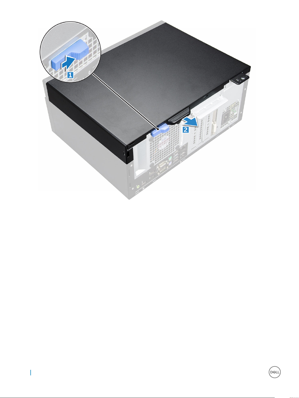
Removing cover
1 Follow the procedure in Before working inside your computer.
2 To release the cover:
a Slide the blue tab to release the cover from the computer [1].
b Slide the cover toward the back of the computer [2].
2
Removing and installing components 9
Page 10
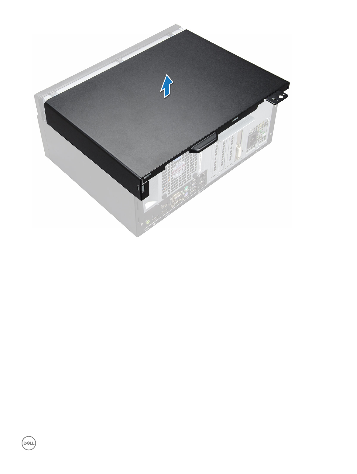
3 Lift the cover to remove it from the computer.
10
Removing and installing components
Page 11
Installing cover
1 Place the cover on the computer and slide the cover forward until it clicks into place.
2 Follow the procedure in After working inside your computer.
Front Bezel
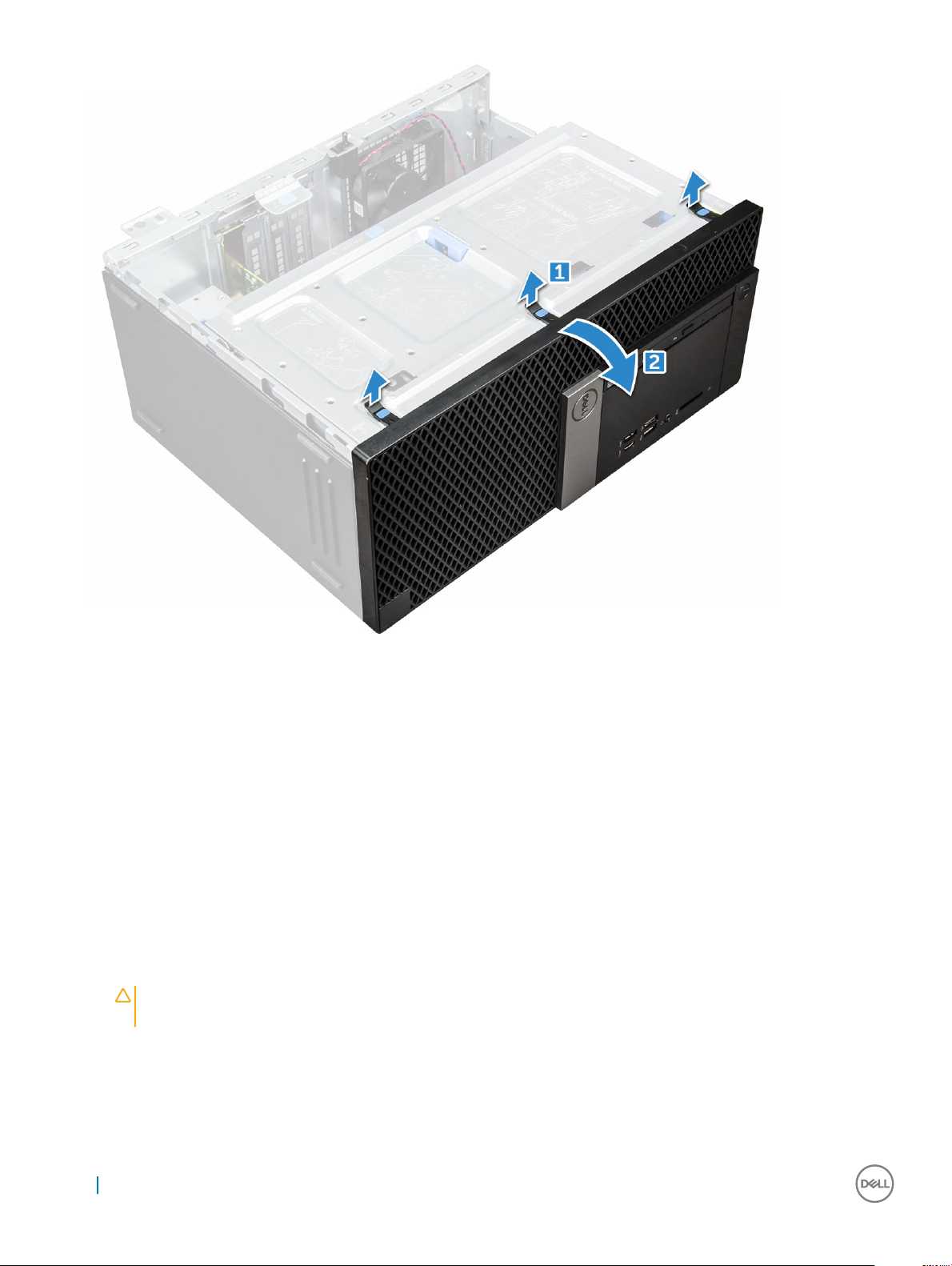
Removing bezel
1 Follow the procedure in Before working inside your computer.
2 Remove the cover.
3 To remove the bezel:
a Lift the tabs to release the bezel from the chassis [1].
b Push the bezel away from the chassis [2].
Removing and installing components
11
Page 12
Installing bezel
1 Position the bezel to align the tab holders on the chassis.
2 Press the bezel until the tabs click into place.
3 Install the cover.
4 Follow the procedure in After working inside your computer.
Opening the front panel door
1 Follow the procedure in Before working inside your computer.
2 Remove the:
a cover
b bezel
CAUTION
maximum permissible level.
3 Pull the front panel door to open it.
12
Removing and installing components
: The front panel door opens only to a limited extent. See the printed image on the front panel door for the
Page 13
Storage
Removing 3.5–inch hard drive assembly
1 Follow the procedure in Before working inside your computer.
2 Remove the:
a cover
b bezel
3 To remove the hard drive assembly:
a Disconnect the hard drive assembly cables from the connectors on the hard drive.
Removing and installing components
13
Page 14
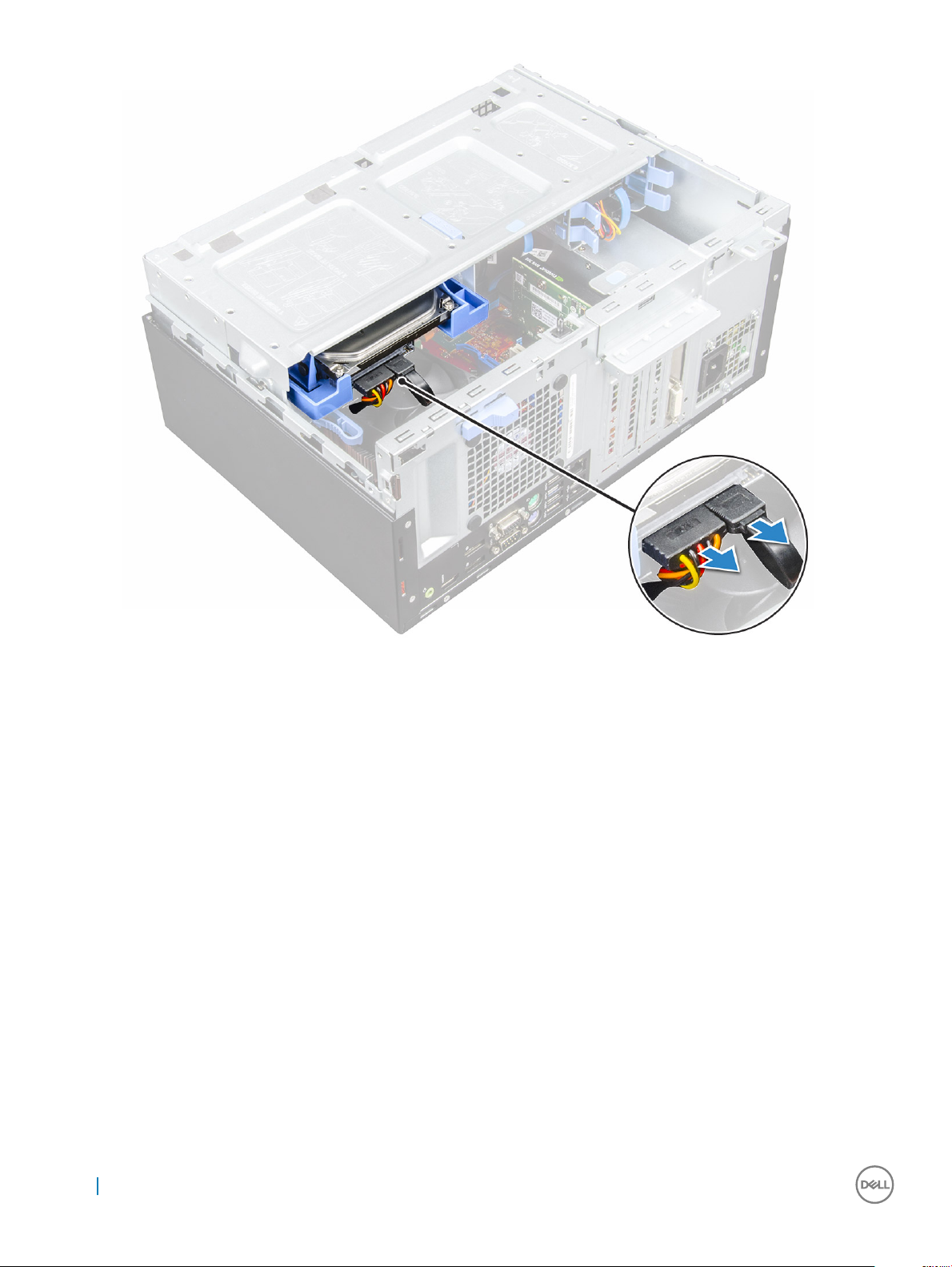
b Press the blue tab [1] and pull the hard drive assembly out of the computer [ 2].
14
Removing and installing components
Page 15
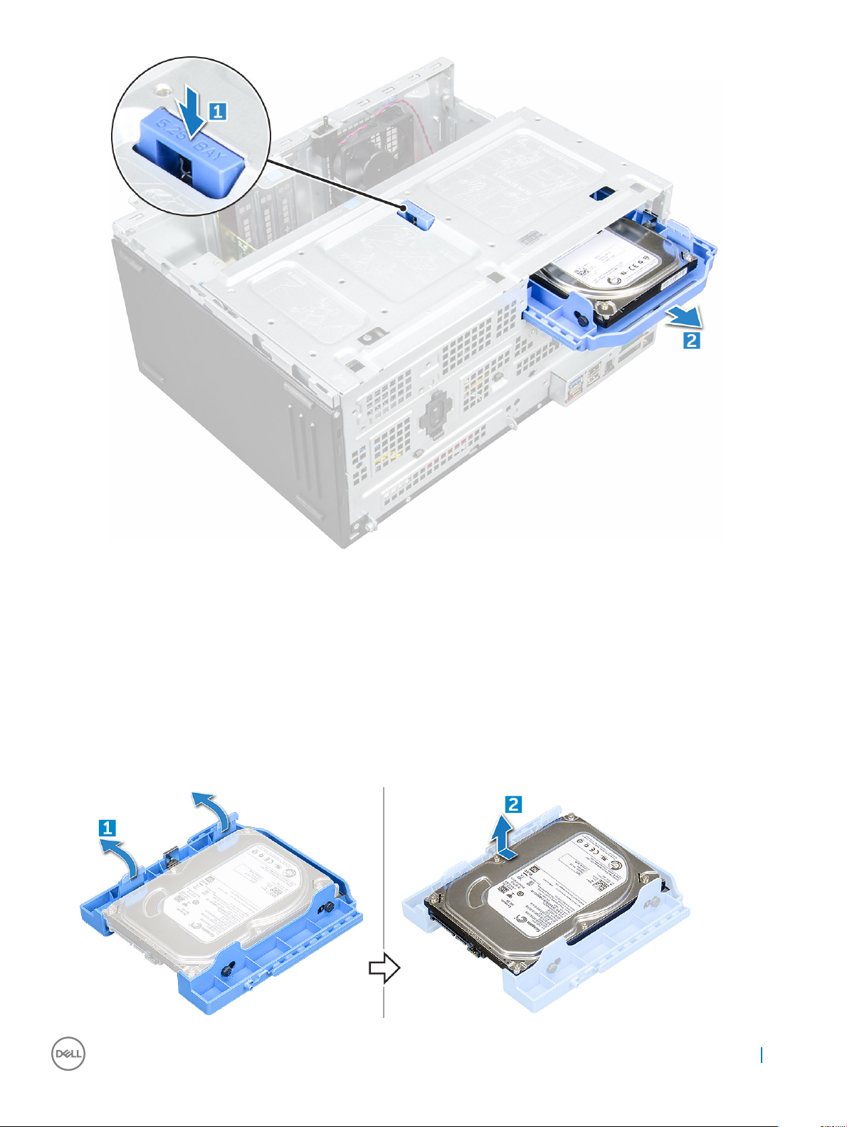
Removing 3.5–inch hard drive from the hard drive bracket
1 Follow the procedure in Before working inside your computer.
2 Remove the:
a cover
b bezel
c hard drive assembly
3 To remove the hard drive bracket:
a Pull one side of the hard drive bracket to disengage the pins on the bracket from the slots on the hard drive [1].
b Lift the hard drive out of the hard drive bracket [2].
Removing and installing components
15
Page 16

Installing 3.5–inch hard drive assembly
1 Insert the hard drive assembly into the slot on the computer until it clicks into place.
2 Close the front panel door.
3 Connect the SATA cable and the power cable to the connectors on the hard drive.
4 Install the:
a bezel
b cover
5 Follow the procedure in After working inside your computer.
Installing the 3.5–inch hard drive into the hard drive bracket
1 Flex the other side of the hard drive bracket, and align and insert the pins on the bracket into the hard drive.
2 Insert the hard drive into the hard drive bracket until it clicks into place.
3 Install the:
a hard drive assembly
b bezel
c cover
4 Follow the procedure in After working inside your computer.
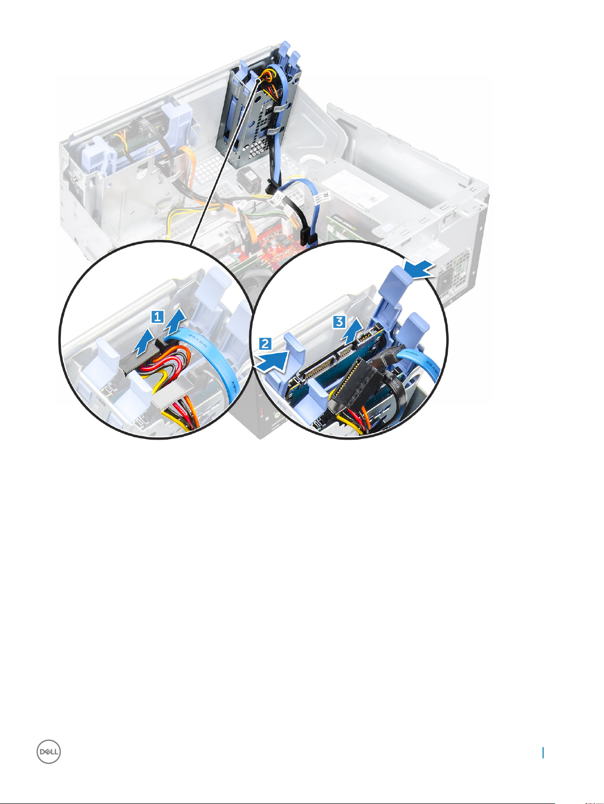
Removing the 2.5–inch drive assembly
1 Follow the procedure in Before working inside your computer.
2 Remove the:
a cover
b bezel
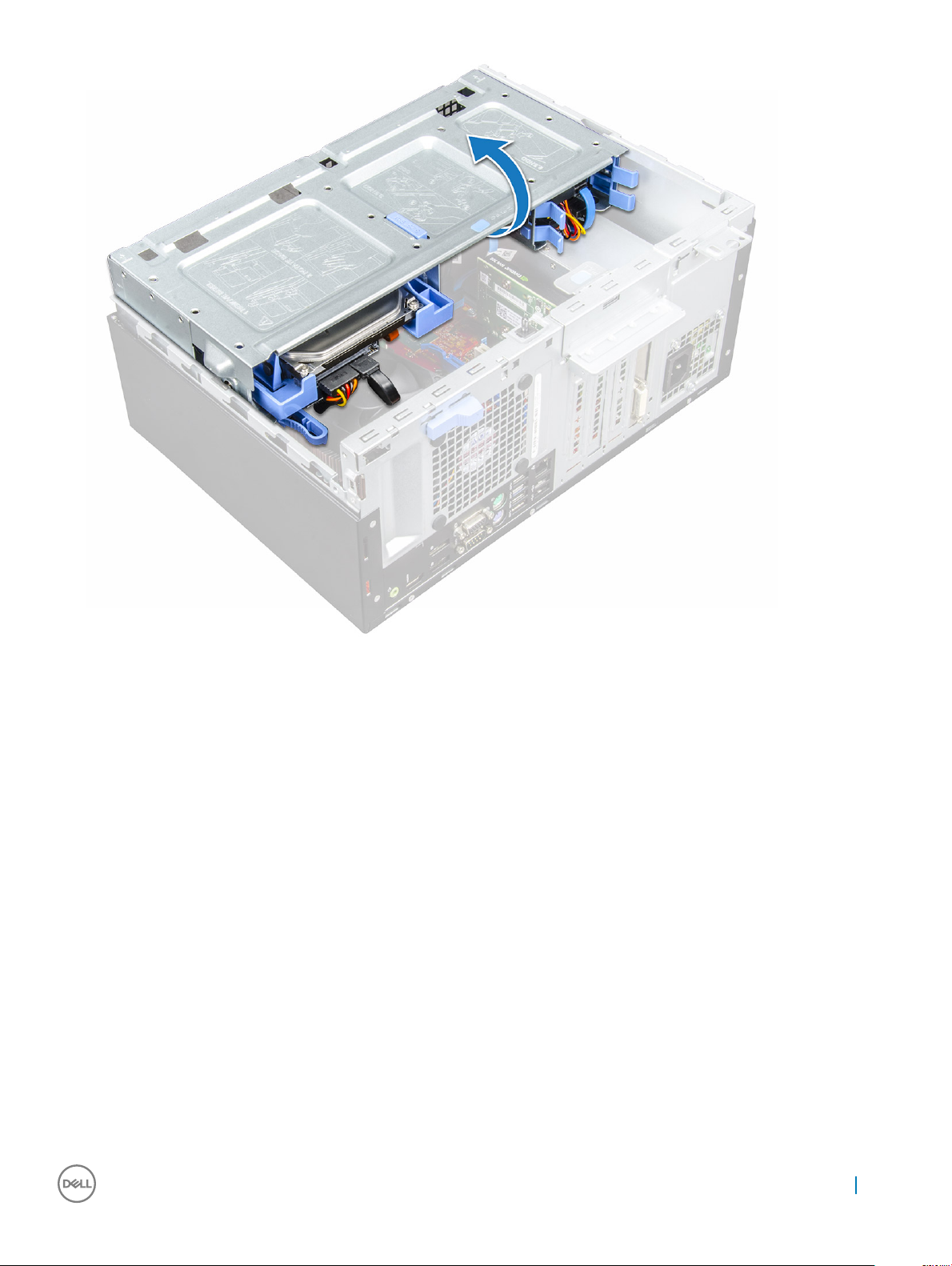
3 Open the front panel door.
4 To remove the drive assembly:
a Disconnect the drive assembly cables from the connectors on the drive [1].
b Press the blue tabs on both sides [2] and pull the drive assembly out of the computer [3].
16
Removing and installing components
Page 17
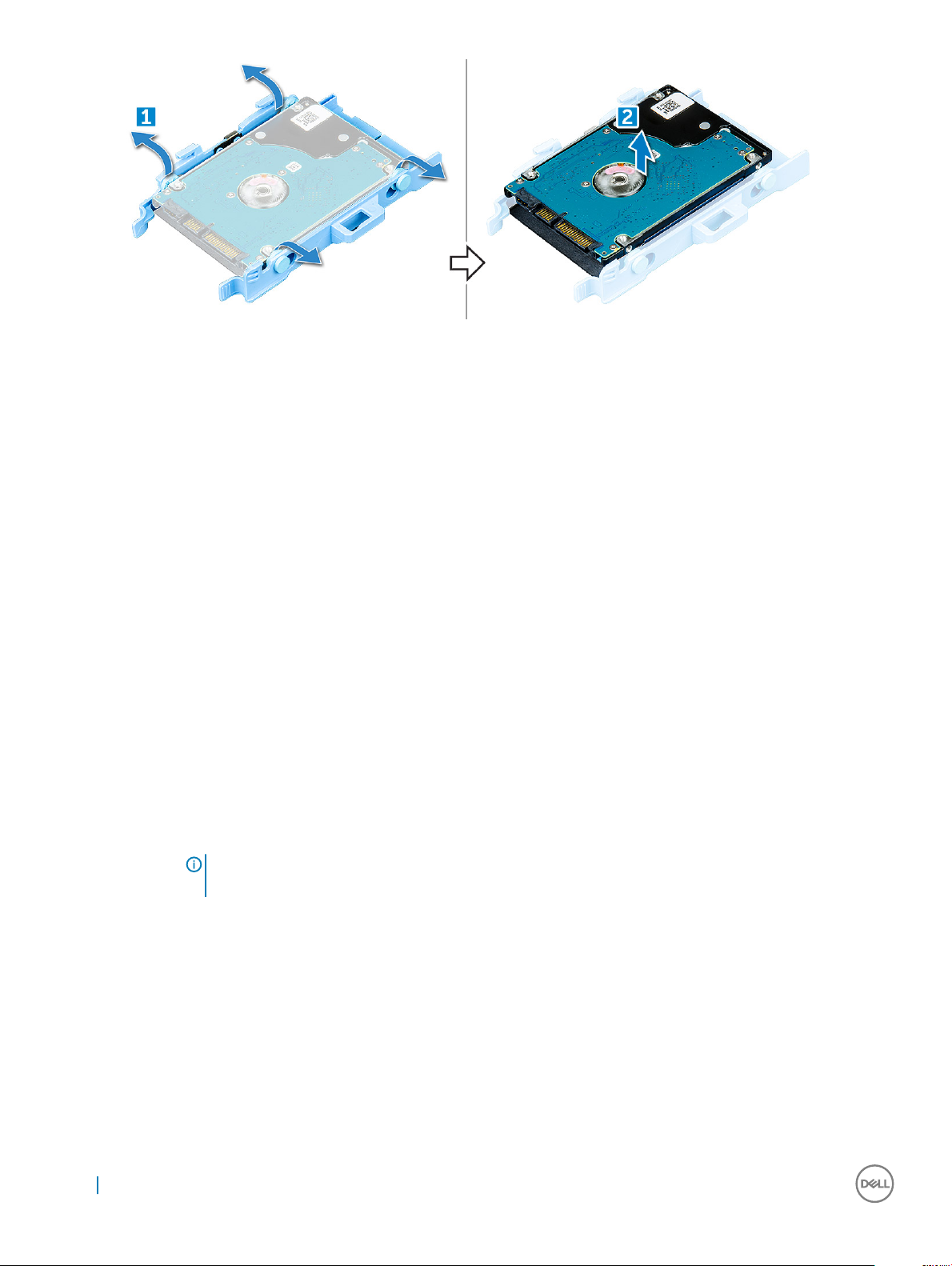
Removing the 2.5–inch drive from the drive bracket
1 Follow the procedure in Before Working Inside Your Computer.
2 Remove the:
a cover
b bezel
c 2.5–inch drive assembly
3 To remove the drive:
a Pull one side of the drive bracket to disengage the pins on the bracket from the slots on the drive [1].
b Lift the drive out of the drive bracket [2].
Removing and installing components
17
Page 18
Installing the 2.5-inch drive assembly
1 Insert the drive assembly into the slot on the computer until it clicks into place.
2 Close the front panel door.
3 Connect the SATA cable and the power cable to the connectors on the drive.
4 Install the:
• bezel
• cover
5 Follow the procedure in After Working Inside Your Computer.
Optical drive
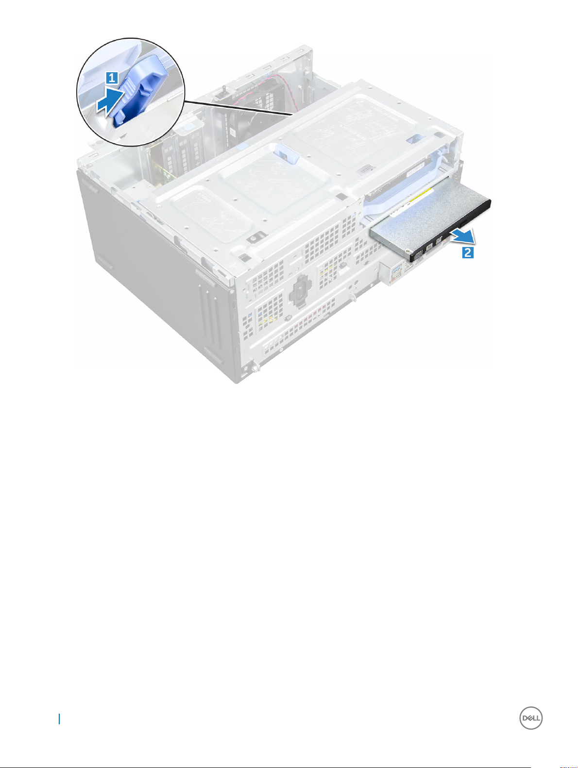
Removing optical drive
1 Follow the procedure in Before working inside your computer.
2 Remove the:
a cover
b bezel
3 Open the front panel door.
4 To remove the optical drive assembly:
a Disconnect the data cable and power cable from the connectors on the optical drive [1].
NOTE
the cables from the connectors.
b Close the front panel door [2].
18
Removing and installing components
: You may need to unroute the cables from the tabs under the drive cage to allow you to disconnect
Page 19
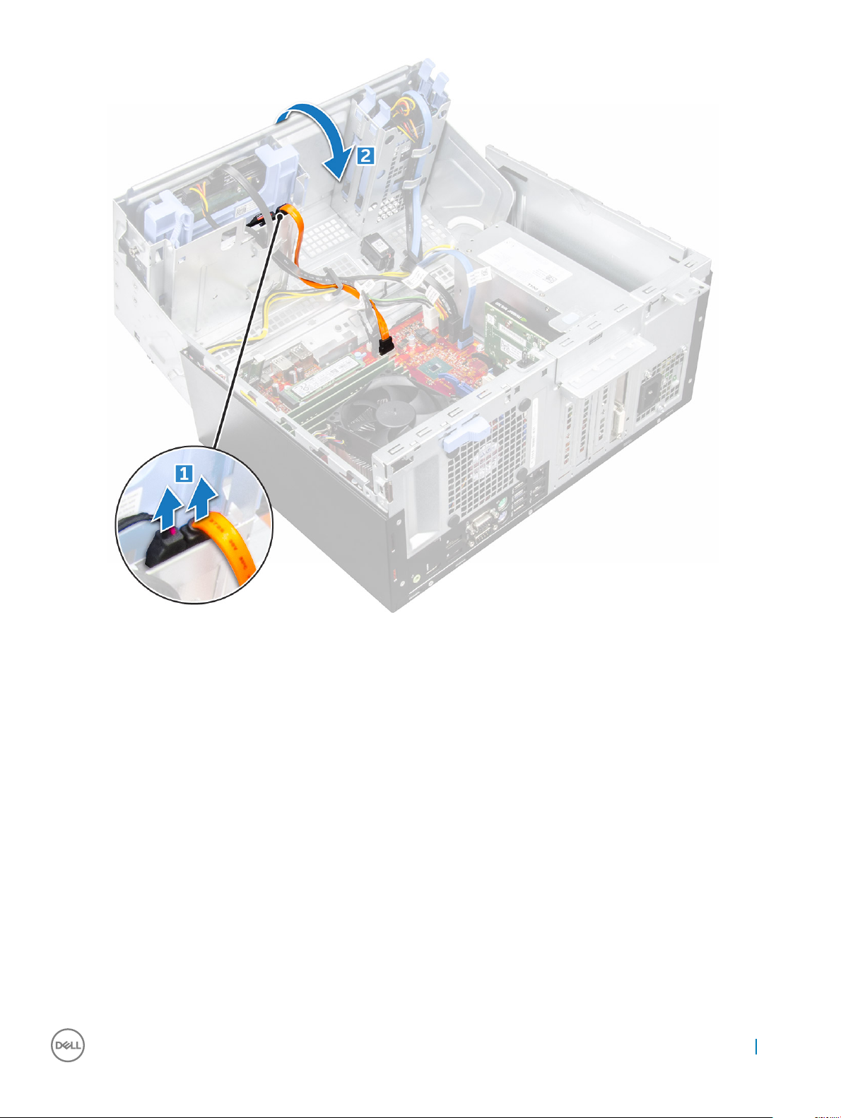
c Press the blue release tab [1] and slide the optical drive out of the computer [2].
Removing and installing components
19
Page 20
Installing optical drive
1 Insert the optical drive into the optical drive bay until it clicks into place.
2 Open the front panel door.
3 Route the data cable and power cable under the drive cage.
4 Connect the data cable and power cable to the connectors on the optical drive.
5 Close the front panel door.
6 Install the:
a bezel
b cover
7 Follow the procedure in After working inside your computer.
M.2 PCIe SSD
Removing optional M.2 PCIe SSD
1 Follow the procedure in Before working inside your computer.
2 Remove the:
a cover
b bezel
20
Removing and installing components
Page 21
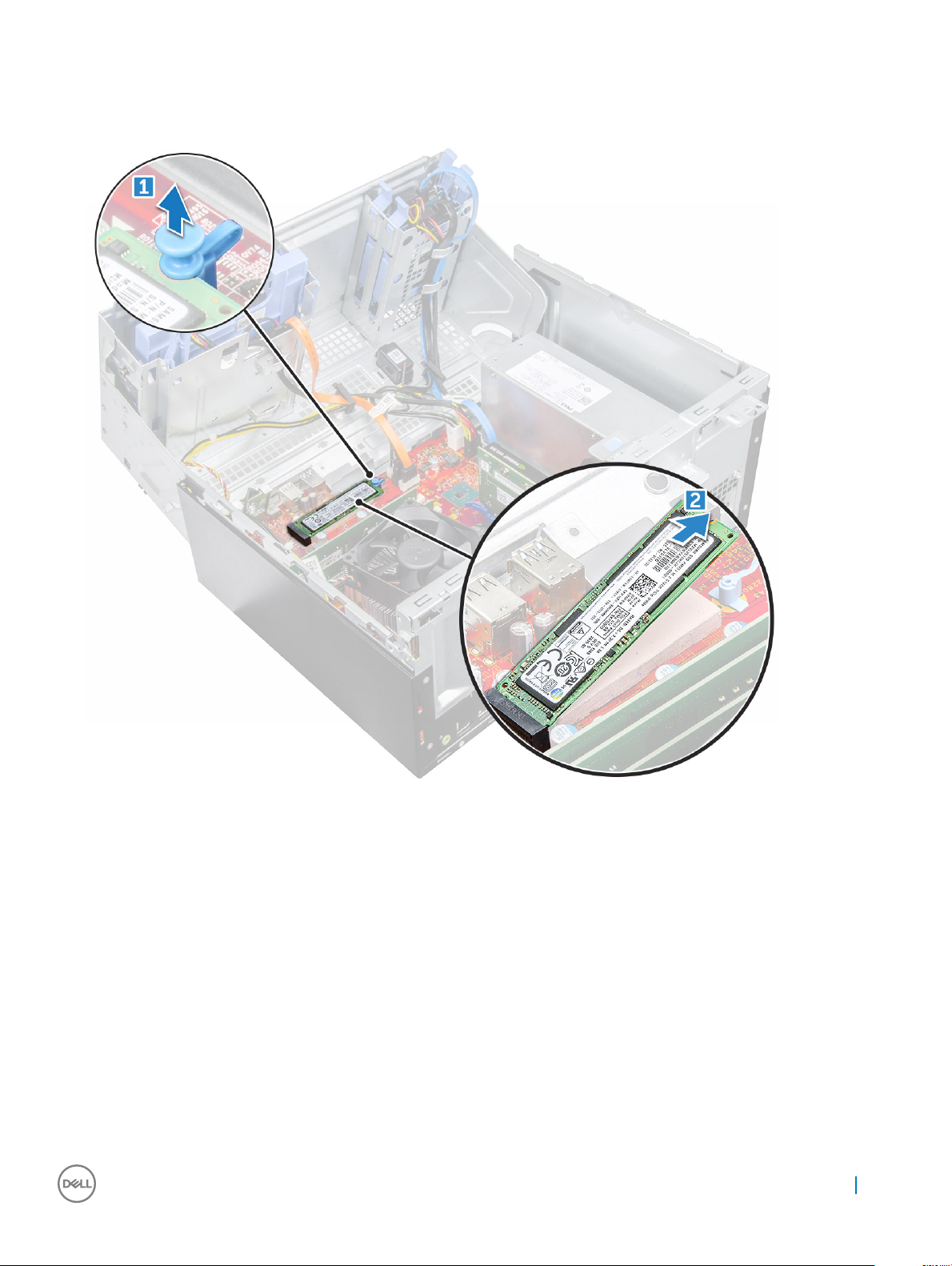
3 Open the front panel door.
4 To remove the M.2 PCIe SSD:
a Pull the blue tab that secures the M.2 PCIe SSD to the system board [1].
b Disconnect the M.2 PCIe SSD from the connector on the system board [2].
Installing optional M.2 PCIe SSD
1 Insert the M.2 PCIe SSD to the connector.
2 Press the blue tab to secure the M.2 PCIe SSD.
3 Close the front panel door.
4 Install the:
a bezel
b cover
5 Follow the procedure in After working inside your computer.
Removing and installing components
21
Page 22
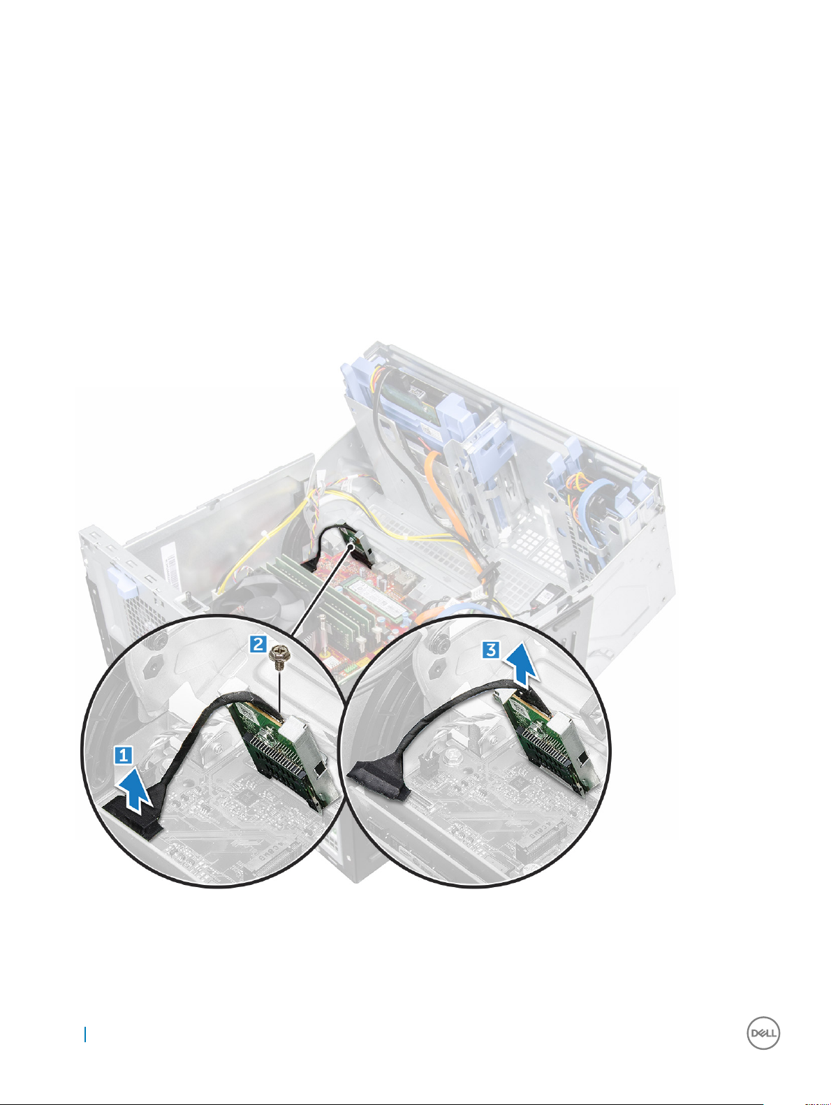
SD card reader
Removing SD card reader
1 Follow the procedure in Before working inside your computer.
2 Remove the:
a cover
b bezel
3 Open the front panel door.
4 To remove the SD card reader:
a Disconnect the SD card reader cable from the connector on the system board [1].
b Remove the screw that secures the SD card reader to the front panel door [2].
c Lift the SD card reader out of the computer [3].
22 Removing and installing components
Page 23
Installing SD card reader
1 Insert the SD card reader into the slot on the system board.
2 Tighten the screw to secure the SD card reader to the front panel door.
3 Connect the SD card reader cable to the connector on the system board.
4 Close the front panel door.
5 Install the:
a bezel
b cover
6 Follow the procedure in After working inside your computer.
Memory module
Removing memory module
1 Follow the procedure in Before working inside your computer.
2 Remove the:
a cover
b bezel
3 Open the front panel door.
4 To remove the memory module:
a Push the memory module retention tabs on both sides of the memory module.
b Lift the memory module from the memory module connector on the system board.
Installing memory module
1 Align the notch on the memory module with the tab on the memory module connector.
2 Insert the memory module into the memory module socket.
3 Press the memory module until the memory module retention tabs click into place.
4 Close the front panel door.
5 Install the:
a cover
b bezel
6 Follow the procedure in After working inside your computer.
Removing and installing components
23
Page 24
Expansion card
Removing PCIe expansion card
1 Follow the procedure in Before working inside your computer.
2 Remove the:
a cover
b bezel
3 Open the front panel door.
4 To remove the PCIe expansion card:
a Pull the release latch to unlock the PCIe expansion card [1].
b Push the card retention latch [2], and lift the PCIe expansion card out of the computer [3].
NOTE: This step is applicable only for the connector with card retention latch, otherwise, lift the PCIe
expansion card out of the computer.
5 Repeat the steps to remove any additional PCIe expansion card.
24
Removing and installing components
Page 25
Installing PCIe expansion card
1 Pull the release latch backward to open [1].
2 To remove the PCIe brackets (1 and 3) as shown below, insert a screwdriver in the hole of a PCIe bracket and push hard to release the
bracket [2], and then lift the bracket out from your computer.
NOTE: To remove the PCIe brackets (2 and 4), push the bracket upwards from the inside of your computer to release it
and then lift the bracket away from your computer.
3 Insert the PCIe expansion card to the connector on the system board.
4 Secure the PCIe expansion card by pushing the card retention latch until it clicks into place.
5 Repeat the steps to install any additional PCIe expansion card.
6 Close the release latch.
7 Close the front panel door.
8 Install the:
a bezel
b cover
Removing and installing components
25
Page 26

9 Follow the procedure in After working inside your computer.
Power supply unit
Removing power supply unit (PSU)
1 Follow the procedure in Before working inside your computer.
2 Remove the:
a cover
b bezel
3 Open the front panel door.
4 To release the PSU:
a Disconnect the PSU cables from the connectors on the system board [1] [2].
b Pull the release clip [3].
c Unroute the PSU cables from the retention clip [4].
d Remove the screws that secure the PSU to the computer [5].
5 To remove the PSU:
a Press the release tab [1].
b Slide and lift the PSU away from the computer [2].
26
Removing and installing components
Page 27

Installing power supply unit (PSU)
1 Insert the PSU into the PSU slot and slide it toward the back of the computer until it clicks into place.
2 Tighten the screws to secure the PSU to the computer.
3 Route the PSU cables through the retention clips.
4 Connect the PSU cables to the connectors on the system board.
5 Close the front panel door.
6 Install the:
a bezel
b cover
7 Follow the procedure in After working inside your computer.
Removing and installing components
27
Page 28

VGA daughter board
Removing VGA daughter board
1 Follow the procedure in Before working inside your computer.
2 Remove the:
a cover
b bezel
3 Open the front panel door
4 To remove the VGA daughter board:
a Remove the screws that secure the VGA connector to the computer [1].
b Slide the VGA connector to release it from the computer.
c Remove the screw that secures the VGA daughter board to the computer [2].
d Lift the VGA daughter board using the handle to remove it from the computer [3].
28 Removing and installing components
Page 29

Installing VGA daughter board
1 Align the VGA daughter board with the screw holder on the system board.
2 Tighten the screw to secure the VGA daughter board to the system board.
3 Insert the VGA connector into the slot at the back of the computer.
4 Tighten the screws to secure the VGA connector to the computer.
5 Close the front panel door.
6 Install the:
a bezel
b cover
7 Follow the procedure in After working inside your computer.
Intrusion switch
Removing intrusion switch
1 Follow the procedure in Before working inside your computer.
2 Remove the:
a cover
b bezel
3 Open the front panel door.
4 To remove the intrusion switch:
a Disconnect the intrusion switch cable from the connector on the system board [1] [2].
b Unroute the intrusion switch cable from the fan grommet.
c Slide the intrusion switch and push it to remove from the computer [3].
Removing and installing components
29
Page 30

Installing intrusion switch
1 Insert the intrusion switch into the slot on the computer.
2 Route the intrusion switch cable through the fan grommet.
3 Connect the intrusion switch cable to the connector on the system board.
4 Close the front panel door.
5 Install the:
a bezel
b cover
6 Follow the procedure in After working inside your computer.
Power switch
Removing power switch
1 Follow the procedure in Before working inside your computer.
2 Remove the:
30
Removing and installing components
Page 31

a cover
b bezel
3 Open the front panel door.
4 To release the power switch:
a Disconnect the power switch cable from the system board [1].
b Unroute the power switch cable through the retention clip [2].
c Press the release tabs using a plastic scribe and slide the power switch out from the front of the computer [2,3].
d Close the front panel door [4].
5 Pull the power switch out from the computer.
Removing and installing components
31
Page 32

Installing power switch
1 Insert the power switch into the slot from the front of the computer and press it until it clicks into place.
2 Route the power switch cable through the retention clip.
3 Align the cable with the pins on the connector and connect the cable.
4 Close the front panel door.
5 Install the:
a bezel
b cover
6 Follow the procedure in After working inside your computer.
Speaker
Removing speaker
1 Follow the procedure in Before working inside your computer.
2 Remove the:
a cover
b bezel
32
Removing and installing components
Page 33

3 Open the front panel door.
4 To remove the speaker:
a Disconnect the speaker cable from the connector on the system board [1].
b Close the front panel door.
c Press the release tabs [1], and slide the speaker [2] out of the slot.
Removing and installing components
33
Page 34

Installing speaker
1 Insert the speaker into the slot and press it until it clicks into place.
2 Connect the speaker cable to the connector on the system board.
3 Close the front panel door.
4 Install the:
a bezel
b cover
5 Follow the procedure in After working inside your computer.
Coin cell battery
Removing coin cell battery
1 Follow the procedure in Before working inside your computer.
2 Remove the:
a cover
b bezel
3 Open the front panel door.
34
Removing and installing components
Page 35

4 To remove the coin cell battery:
a Press the release latch until the coin cell battery pops out [1].
b Remove the coin cell battery from the connector on the system board [2].
Installing the coin cell battery
1 Hold the coin cell battery with the "+" sign facing up and slide it under the securing tabs at the positive side of the connector.
2 Press the battery into the connector until it locks into place.
3 Close the front panel door.
4 Install the:
• bezel
• cover
5 Follow the procedure in After working inside your computer.
Removing and installing components
35
Page 36

Heat sink assembly
Removing heat sink assembly
1 Follow the procedure in Before working inside your computer.
2 Remove the:
a cover
b bezel
3 Open the front panel door.
4 To remove the heat sink assembly:
a Disconnect the heat sink assembly cable from the connector on the system board [1].
b Loosen the captive screws that secure the heat sink assembly to the system board [2].
c Lift the heat sink assembly away from the computer [3].
36 Removing and installing components
Page 37

Installing heat sink assembly
1 Align the screws of the heat sink assembly with the holders on the system board.
2 Place the heat sink assembly on the processor.
3 Tighten the captive screws to secure the heat sink assembly to the system board.
4 Connect the heat sink assembly cable to the connector on the system board.
5 Close the front panel door.
6 Install the:
a bezel
b cover
7 Follow the procedure in After working inside your computer.
Processor
Removing processor
1 Follow the procedure in Before working inside your computer.
2 Remove the:
a cover
b bezel
3 Open the front panel door.
4 Remove the heat sink assembly.
5 To remove the processor:
a Release the socket lever by pushing the lever down and out from under the tab on the processor shield [1].
b Lift the lever upward and lift the processor shield [2].
c Lift the processor out of the socket [3].
CAUTION
careful not to bend the pins in the processor socket when removing the processor out of the socket.
: Do not touch the processor socket pins, they are fragile and can be permanently damaged. Be
Removing and installing components 37
Page 38

Installing processor
1 Align the processor with the socket keys.
CAUTION
socket.
2 Align the pin-1 indicator of the processor with the triangle on the socket.
3 Place the processor on the socket such that the slots on the processor align with the socket keys.
4 Close the processor shield by sliding it under the retention screw.
5 Lower the socket lever and push it under the tab to lock it.
6 Install the heat sink assembly.
7 Close the front panel door.
8 Install the:
a bezel
b cover
9 Follow the procedure in After working inside your computer.
38
Removing and installing components
: Do not use force to seat the processor. When the processor is positioned correctly, it engages easily into the
Page 39

System fan
Removing system fan
1 Follow the procedure in Before working inside your computer.
2 Remove the:
a cover
b bezel
c intrusion switch
3 Open the front panel door.
4 To remove the system fan:
a Disconnect the system fan cable from the connector on the system board [1].
b Remove the tape that holds the intrusion switch cable on the system fan and move the cable away.
c Stretch the grommets securing the fan to the computer to ease the removal of the fan [2].
d Slide the system fan out of the computer [3].
Removing and installing components 39
Page 40

Installing system fan
1 Insert the grommets into the slots on the back of the computer.
2 Hold the system fan with the cable facing the bottom of the computer.
3 Align the grooves of the system fan with the grommets on the chassis wall.
4 Pass the grommets through the corresponding grooves on the system fan.
5 Stretch the grommets and slide the system fan toward the computer until it locks into place.
NOTE: Install the lower two grommets rst.
6 Secure the intrusion switch cable to the system fan with an adhesive tape.
7 Connect the system fan cable to the connector on the system board.
8 Close the front panel door.
9 Install the:
a intrusion switch
b bezel
c cover
10 Follow the procedure in After working inside your computer.
System board
Removing system board
1 Follow the procedure in Before working inside your computer.
2 Remove the:
a cover
b bezel
3 Open the front panel door.
4 Remove the:
a heat sink assembly
b processor
c expansion card
d optional M.2 PCIe SSD
e SD card reader
f memory module
g VGA daughter board
5 Disconnect the optical drive and hard drive cables [1,2] from the connectors on the system board.
40
Removing and installing components
Page 41

6 Disconnect the following cables from the system board:
a PSU [1]
b power switch [2]
c speaker [3]
d PSU [4]
e power distribution for optical drive and hard drive [5]
f system fan [6]
g intrusion switch [7]
Removing and installing components
41
Page 42

7 To remove the system board:
a Remove the screws that secure the system board to the computer [1].
b Slide and lift the system board away from the computer [2].
42
Removing and installing components
Page 43

Installing the system board
1 Hold the system board by its edges and align it toward the back of the computer.
2 Lower the system board into the computer until the connectors at the back of the system board align with the slots on the chassis,
and the screw holes on the system board align with the standos on the computer.
3 Tighten the screws to secure the system board to the computer.
4 Route all the cables through the routing clips.
5 Align the cables with the pins on connectors on the system board and connect the following cables to the system board:
a intrusion switch
b system fan
c power distribution for optical drive and hard drive
d PSU (2 cables)
e optical dive and hard drive cables (4 cables)
f speaker
g power switch
6 Install the:
Removing and installing components
43
Page 44

a memory module
b optional M.2 PCIe SSD
c expansion card
d SD card reader
e processor
f heat sink assembly
g VGA daughter board
7 Close the front panel door.
8 Install the:
a bezel
b cover
9 Follow the procedure in After working inside your computer.
44 Removing and installing components
Page 45

3
M.2 Intel Optane Memory Module 16 GB
Overview
This document describes the specications and capabilities of the Intel® OptaneTM memory module. The Intel® OptaneTM memory is a
system acceleration solution developed for 7th Generation Intel® CoreTM processor-based platforms. The Intel® OptaneTM memory
module is architected with the high performance controller interface Non-Volatile Memory Express (NVMe*)- delivering outstanding
performance, low latency and quality of service. NVMe uses a standardized interface that enables higher performance and lower latency
than pervious interfaces. Intel® OptaneTM memory module oers capacities of 16 GB and 32 GB in small M.2 form factors.
The Intel® OptaneTMmemory module oers a system acceleration solution using the latest Intel® Rapid Storage Technology (Intel® RST)
15.5X.
The Intel® OptaneTM memory module includes these key features:
• PCIe 3.0x2 with NVMe interface
• Uses Intel’s revolutionary new storage technology, 3D XpointTM memory media
• Ultra-low latency; exceptional responsiveness
• Performance saturation at queue depth of 4 and lower
• Very high endurance capabilities
Intel®Optane
The following table describes the driver requirements for the Intel® OptaneTM memory system acceleration us a component of Intel®
Rapid Storgae Technology 15.5 or later and requires 7th generation Intel® Core TM processor-based platforms to function.
Table 1. Driver Support
Support Level Operating System Description
Intel® OptaneTM Memory with System Acceleration Conguration
Using Rapid Storage Technology Driver
NOTES:
1 Intel® RST driver requires device to be attached to RST enabled PCIe lanes on 7th generation Intel® CoreTM.
TM
Memory Module Driver Requirements
Windows 10*64 bit
1
M.2 Intel Optane Memory Module 16 GB
1 Follow the procedure in Before working inside your computer.
2 Remove the cover.
3 To remove M.2 Intel optane memory module:
a Remove the thermal pad and white adhesive tape from the box.
M.2 Intel Optane Memory Module 16 GB 45
Page 46

b Place the thermal pad on the SSD slot and remove the white adhesive tape.
c Place the M.2 Intel optane memory module into the slot on the thermal pad.
46
M.2 Intel Optane Memory Module 16 GB
Page 47

d If the system is shipped with screw tighten that secures the M.2 Intel optane memory module on the computer. If the system is
shipped with self locking spacer press to lock the M.2 Intel optane to secure on the computer.
Product specications
Features
Capacities 16 GB, 32 GB
Expansion cards PCIe 3.0 x 2
M.2 form factors (all densities) 2280–S3–B-M
Performace
Latency (average sequential)
Components
Operating System Support Windows 10 64 bit
Specication
• Seq R/W: Up to 1350/290 MS/s
• QD4 4HB Random Read: 240K + IOPs
• QD4 4HB Random Write: 240K + IOPs
• Read 8.25 µ
• Write: 30 µ
• Intel 3D XPoint Memory Media
• Intel Controller and Firmware
• PCIe 3.0x2 with NVMe Interface
• Intel Rapid Storage Technology 15.2 or later
M.2 Intel Optane Memory Module 16 GB 47
Page 48

Supported Platforms 7th generation or newer Intel Core processor based platforms
Power
• 3.3V Supply Rail
• Active: 3.5 W
• Drive Idel :900mW to 1.2W
Compliance
• NVMe Express 1.1
• PCI Express Base speciation rev 3.0
• PCI M.2 HS Spec
Certication and Declarationsµ UL, CE, C-Tick, BSMI, KCC, Microsoft WHQL, Microsoft WHCK,
VCCI
Endurance Rating
• 100 GB Writes per day
• Upto 182.3 TBW (Terabytes written)
Temperature Specication
• Operating: 0 to 70º C
• Non-Opearting: 10 to 85º C
• Temperature monitoring
Shock 1500 G/0.5msec
Vibration
Altitude (Simulated)
• Operating: 2.17 G
• Non-Operating: 3.13 G
(5–800Hz)
RMs
RMS
(5–800Hz)
• Operating: –1,000 ft to 10,000 ft
• Non-Operating: –1,000 ft to 40,000 ft
Product Ecological Compliance RoHS
Reliability
• Uncorrectable Bit Error Rate (UBER): 1 sector per 1015 bits read
• Mean Time Between Failure (MTBF): 1.6 million hours
Environmental Conditions
Table 2. Temperature, Shock, Vibration
Temperature M.2 2280 form factor
Operating
Non-operating
Temperature Gradient
Operating
Non-operating
Humidity
Operating
Non-operating
1
2
3
0–70º C
-10–85º C
30º C/hr (Typical)
30º C/hr (Typical)
5–95%
5–95%
Shock and Vibration Range
4
Shock
48 M.2 Intel Optane Memory Module 16 GB
Page 49

Operating
1500 G / 0.5 ms
Non-operating
Vibration
Operating
Non-operating
NOTES:
1 Operating temperature is targeted for 70º C.
2 Please contact your Intel representative for details on the non-operating temperature range.
3 Temperature gradient measured without condensation.
4 Shock specication assume the device is mounted securely with the input vibration applied to the drive-mounting screws. Stimulus
5 Vibration specications assume the device is mounted securely with the input vibration applied to the drive-mounting screws.
5
may be applied in the X,Y, or Z axis shock specication is measured using Root Mean Squared (RMS) value.
Stimulus may be applied in the X, Y, or Z axis. Vibration specicities is measured using RMS value.
230 G / 3 msec
2.17 G
3.13 G
(5–800Hz) Max
RMS
(5–800Hz) Max
RMS
Troubleshooting
1 The Intel Optane Memory model name "NVME INTEL MEMPEK1W01" in Device Manager does not match in the Intel Rapid Storage
Technology user interface; it only shows a part of the serial number information. This is a known issue and does not impede the
functionality of the Intel Optane Memory.
Device Manager: NVME INTEL MEMPEK1W01
IRST UI: INTEL MEMPEK1W016GA
2 During the rst-time boot up, the system will scan the pairing status as below screen shot after shutdown. It’s working as designed
and the message will not appear again in following boot ups.
M.2 Intel Optane Memory Module 16 GB
49
Page 50

Technology and components
USB features
The Universal Serial Bus, or well known as USB was introduced to the PC world in 1996 which dramatically simplied the connection
between host computer and peripheral devices such as mice and keyboards, external hard drive or optical devices, Bluetooth and many
more peripheral devices in the market.
Let's take a quick look on the USB evolution referencing to the table below.
Table 3. USB evolution
Type Data Transfer Rate Category Introduction Year
USB 3.0/USB 3.1 Gen 1 5 Gbps Super Speed 2010
USB 2.0 480 Mbps High Speed 2000
USB 1.1 12 Mbps Full Speed 1998
USB 1.0 1.5 Mbps Low Speed 1996
4
USB 3.0/USB 3.1 Gen 1 (SuperSpeed USB)
For years, the USB 2.0 has been rmly entrenched as the de facto interface standard in the PC world with about 6 billion devices sold, and
yet the need for more speed grows by ever faster computing hardware and ever greater bandwidth demands. The USB 3.0/USB 3.1 Gen 1
nally has the answer to the consumers' demands with a theoretically 10 times faster than its predecessor. In a nutshell, USB 3.1 Gen 1
features are as follows:
• Higher transfer rates (up to 5 Gbps)
• Increased maximum bus power and increased device current draw to better accommodate power-hungry devices
• New power management features
• Full-duplex data transfers and support for new transfer types
• Backward USB 2.0 compatibility
• New connectors and cable
The topics below cover some of the most commonly asked questions regarding USB 3.0/USB 3.1 Gen 1.
Speed
Currently, there are 3 speed modes dened by the latest USB 3.0/USB 3.1 Gen 1 specication. They are Super-Speed, Hi-Speed and FullSpeed. The new SuperSpeed mode has a transfer rate of 4.8Gbps. While the specication retains Hi-Speed, and Full-Speed USB mode,
50 Technology and components
Page 51

commonly known as USB 2.0 and 1.1 respectively, the slower modes still operate at 480Mbps and 12Mbps respectively and are kept to
maintain backward compatibility.
USB 3.0/USB 3.1 Gen 1 achieves the much higher performance by the technical changes below:
• An additional physical bus that is added in parallel with the existing USB 2.0 bus (refer to the picture below).
• USB 2.0 previously had four wires (power, ground, and a pair for dierential data); USB 3.0/USB 3.1 Gen 1 adds four more for two pairs
of dierential signals (receive and transmit) for a combined total of eight connections in the connectors and cabling.
• USB 3.0/USB 3.1 Gen 1 utilizes the bidirectional data interface, rather than USB 2.0's half-duplex arrangement. This gives a 10-fold
increase in theoretical bandwidth.
With today's ever increasing demands placed on data transfers with high-denition video content, terabyte storage devices, high megapixel
count digital cameras etc., USB 2.0 may not be fast enough. Furthermore, no USB 2.0 connection could ever come close to the 480Mbps
theoretical maximum throughput, making data transfer at around 320Mbps (40MB/s) — the actual real-world maximum. Similarly, USB
3.0/USB 3.1 Gen 1 connections will never achieve 4.8Gbps. We will likely see a real-world maximum rate of 400MB/s with overheads. At this
speed, USB 3.0/USB 3.1 Gen 1 is a 10x improvement over USB 2.0.
Applications
USB 3.0/USB 3.1 Gen 1 opens up the laneways and provides more headroom for devices to deliver a better overall experience. Where USB
video was barely tolerable previously (both from a maximum resolution, latency, and video compression perspective), it's easy to imagine
that with 5-10 times the bandwidth available, USB video solutions should work that much better. Single-link DVI requires almost 2Gbps
throughput. Where 480Mbps was limiting, 5Gbps is more than promising. With its promised 4.8Gbps speed, the standard will nd its way
into some products that previously weren't USB territory, like external RAID storage systems.
Listed below are some of the available SuperSpeed USB 3.0/USB 3.1 Gen 1 products:
• External Desktop USB 3.0/USB 3.1 Gen 1 Hard Drives
• Portable USB 3.0/USB 3.1 Gen 1 Hard Drives
• USB 3.0/USB 3.1 Gen 1 Drive Docks & Adapters
• USB 3.0/USB 3.1 Gen 1 Flash Drives & Readers
• USB 3.0/USB 3.1 Gen 1 Solid-state Drives
• USB 3.0/USB 3.1 Gen 1 RAIDs
• Optical Media Drives
• Multimedia Devices
• Networking
• USB 3.0/USB 3.1 Gen 1 Adapter Cards & Hubs
Technology and components
51
Page 52

Compatibility
The good news is that USB 3.0/USB 3.1 Gen 1 has been carefully planned from the start to peacefully co-exist with USB 2.0. First of all,
while USB 3.0/USB 3.1 Gen 1 species new physical connections and thus new cables to take advantage of the higher speed capability of
the new protocol, the connector itself remains the same rectangular shape with the four USB 2.0 contacts in the exact same location as
before. Five new connections to carry receive and transmitted data independently are present on USB 3.0/USB 3.1 Gen 1 cables and only
come into contact when connected to a proper SuperSpeed USB connection.
Windows 8/10 will be bringing native support for USB 3.1 Gen 1 controllers. This is in contrast to previous versions of Windows, which
continue to require separate drivers for USB 3.0/USB 3.1 Gen 1 controllers.
Microsoft announced that Windows 7 would have USB 3.1 Gen 1 support, perhaps not on its immediate release, but in a subsequent Service
Pack or update. It is not out of the question to think that following a successful release of USB 3.0/USB 3.1 Gen 1 support in Windows 7,
SuperSpeed support would trickle down to Vista. Microsoft has conrmed this by stating that most of their partners share the opinion that
Vista should also support USB 3.0/USB 3.1 Gen 1.
Super-Speed support for Windows XP is unknown at this point. Given that XP is a seven-year-old operating system, the likelihood of this
happening is remote.
HDMI 1.4
This topic explains the HDMI 1.4 and its features along with the advantages.
HDMI (High-Denition Multimedia Interface) is an industry-supported, uncompressed, all-digital audio/video interface. HDMI provides an
interface between any compatible digital audio/video source, such as a DVD player, or A/V receiver and a compatible digital audio and/or
video monitor, such as a digital TV (DTV). The intended applications for HDMI TVs, and DVD players. The primary advantage is cable
reduction and content protection provisions. HDMI supports standard, enhanced, or high-denition video, plus multichannel digital audio on
a single cable.
NOTE
: The HDMI 1.4 will provide 5.1 channel audio support.
HDMI 1.4 Features
• HDMI Ethernet Channel - Adds high-speed networking to an HDMI link, allowing users to take full advantage of their IP-enabled
devices without a separate Ethernet cable
• Audio Return Channel - Allows an HDMI-connected TV with a built-in tuner to send audio data "upstream" to a surround audio system,
eliminating the need for a separate audio cable
• 3D - Denes input/output protocols for major 3D video formats, paving the way for true 3D gaming and 3D home theater applications
• Content Type - Real-time signaling of content types between display and source devices, enabling a TV to optimize picture settings
based on content type
• Additional Color Spaces - Adds support for additional color models used in digital photography and computer graphics
• 4 K Support - Enables video resolutions far beyond 1080p, supporting next-generation displays that will rival the Digital Cinema systems
used in many commercial movie theaters
• HDMI Micro Connector - A new, smaller connector for phones and other portable devices, supporting video resolutions up to 1080p
• Automotive Connection System - New cables and connectors for automotive video systems, designed to meet the unique demands of
the motoring environment while delivering true HD quality
Advantages of HDMI
• Quality HDMI transfers uncompressed digital audio and video for the highest, crispest image quality.
• Low -cost HDMI provides the quality and functionality of a digital interface while also supporting uncompressed video formats in a
simple, cost-eective manner
52
Technology and components
Page 53

• Audio HDMI supports multiple audio formats from standard stereo to multichannel surround sound
• HDMI combines video and multichannel audio into a single cable, eliminating the cost, complexity, and confusion of multiple cables
currently used in A/V systems
• HDMI supports communication between the video source (such as a DVD player) and the DTV, enabling new functionality
Technology and components 53
Page 54

System setup
System Setup enables you to manage your desktop hardware and specify BIOS level options. From the System Setup, you can:
• Change the NVRAM settings after you add or remove hardware
• View the system hardware conguration
• Enable or disable integrated devices
• Set performance and power management thresholds
• Manage your computer security
Topics:
• Boot Sequence
• Navigation Keys
• System and setup password
• System Setup options
• Updating the BIOS in Windows
• Updating your system BIOS using a USB ash drive
• Enabling smart power on
5
Boot Sequence
Boot Sequence allows you to bypass the System Setup–dened boot device order and boot directly to a specic device (for example:
optical drive or hard drive). During the Power-on Self Test (POST), when the Dell logo appears. you can:
• Access System Setup by pressing F2 key
• Bring up the one-time boot menu by pressing F12 key
The one-time boot menu displays the devices that you can boot from including the diagnostic option. The boot menu options are:
• Removable Drive (if available)
• STXXXX Drive
NOTE
: XXX denotes the SATA drive number.
• Optical Drive (if available)
• Diagnostics
: Choosing Diagnostics, will display the ePSA diagnostics screen.
NOTE
The boot sequence screen also displays the option to access the System Setup screen.
Navigation Keys
The following table displays the system setup navigation keys.
: For most of the system setup options, changes that you make are recorded but do not take eect until you re-start the
NOTE
system.
54 System setup
Page 55

Table 4. Navigation Keys
Keys Navigation
Up arrow Moves to the previous eld.
Down arrow Moves to the next eld.
<Enter> Allows you to select a value in the selected eld (if applicable) or follow the link in the eld.
Spacebar Expands or collapses a drop‐down list, if applicable.
<Tab> Moves to the next focus area.
NOTE: For the standard graphics browser only.
<Esc> Moves to the previous page till you view the main screen. Pressing <Esc> in the main screen displays a message
that prompts you to save any unsaved changes and restarts the system.
<F1> Displays the System Setup help le.
System and setup password
You can create a system password and a setup password to secure your computer.
Password type Description
System password Password that you must enter to log on to your system.
Setup password Password that you must enter to access and make changes to the BIOS settings of your computer.
CAUTION: The password features provide a basic level of security for the data on your computer.
CAUTION: Anyone can access the data stored on your computer if it is not locked and left unattended.
NOTE: Your computer is shipped with the system and setup password feature disabled.
Assigning a system password and setup password
You can assign a new System Password only when the status is in Not Set.
To enter the system setup, press F2 immediately after a power-on or re-boot.
1 In the System BIOS or System Setup screen, select Security and press Enter.
The Security screen is displayed.
2 Select System Password and create a password in the Enter the new password eld.
Use the following guidelines to assign the system password:
• A password can have up to 32 characters.
• The password can contain the numbers 0 through 9.
• Only lower case letters are valid, upper case letters are not allowed.
• Only the following special characters are allowed: space, (”), (+), (,), (-), (.), (/), (;), ([), (\), (]), (`).
3 Type the system password that you entered earlier in the Conrm new password eld and click OK.
4 Press Esc and a message prompts you to save the changes.
5 Press Y to save the changes.
The computer reboots.
System setup
55
Page 56

Deleting or changing an existing system and/or setup password
Ensure that the Password Status is Unlocked (in the System Setup) before attempting to delete or change the existing System and/or
Setup password. You cannot delete or change an existing System or Setup password, if the Password Status is Locked.
To enter the System Setup, press F2 immediately after a power-on or reboot.
1 In the System BIOS or System Setup screen, select System Security and press Enter.
The System Security screen is displayed.
2 In the System Security screen, verify that Password Status is Unlocked.
3 Select System Password, alter or delete the existing system password and press Enter or Tab.
4 Select Setup Password, alter or delete the existing setup password and press Enter or Tab.
NOTE: If you change the System and/or Setup password, re-enter the new password when promoted. If you delete the
System and/or Setup password, conrm the deletion when promoted.
5 Press Esc and a message prompts you to save the changes.
6 Press Y to save the changes and exit from System Setup.
The computer reboots.
System Setup options
: Depending on the computer and its installed devices, the items listed in this section may or may not appear.
NOTE
Table 5. General
Option Description
System Information Displays the following information:
• System Information: Displays BIOS Version, Service Tag, Asset Tag, Ownership Tag, Ownership
Date, Manufacture Date, and the Express Service Code.
• Memory Information: Displays Memory Installed, Memory Available, Memory Speed, Memory
Channel Mode, Memory Technology, DIMM 1 Size, and DIMM 2 Size, DIMM 3 Size, and DIMM
4 Size.
• PCI Information: Displays SLOT1, SLOT2, SLOT3, SLOT4, and SLOT5_M.2
• Processor Information: Displays Processor Type, Core Count, Processor ID, Current Clock
Speed, Minimum Clock Speed, Maximum Clock Speed, Processor L2 Cache, Processor L3
Cache, HT Capable, and 64-Bit Technology.
• Device Information: Displays SATA-0, SATA-1, SATA-2, SATA-3, SATA-4, M.2 PCIe SSD-0,
LOM MAC Address, Video Controller, and Audio Controller. .
Boot Sequence Allows you to specify the order in which the computer attempts to nd an operating system from the
devices specied in this list.
• Legacy
• UEFI (selected by default)
Advanced Boot Options Allows you to select the Enable Legacy Option ROMs option, when in UEFI boot mode. By default,
this option is selected.
Date/Time Allows you to set the date and time settings. Changes to the system date and time take eect
immediately.
56 System setup
Page 57

Table 6. System Conguration
Option Description
Integrated NIC Allows you to control the on-board LAN controller. The option ‘Enable UEFI Network Stack’ is not
selected by default. The options are:
• Disabled
• Enabled
• Enabled w/PXE (default)
NOTE: Depending on the computer and its installed devices, the items listed in this section
may or may not appear.
SATA Operation Allows you to congure the operating mode of the integrated hard drive controller.
• Disabled = The SATA controllers are hidden
• RAID ON = SATA is congured to support RAID mode (selected by default)
• AHCI= SATA is congured for AHCI mode
Serial Port Allows you to determine how the built-in serial port to operate. The options are:
• Disabled
• COM 1 – Default setting
• COM 2
• COM 3
• COM 4
Drives Allows you to enable or disable the various drives on-board:
• SATA-0
• SATA-1
• SATA-2
• SATA-3
• SATA-4
Smart Reporting This eld controls whether hard drive errors for integrated drives are reported during system startup.
The Enable Smart Reporting option is disabled by default.
USB Conguration Allows you to enable or disable the integrated USB controller for:
• Enable Boot Support
• Enable Front USB Ports
• Enable Rear USB Ports
All the options are enabled by default.
Front USB Conguration Allows you to enable or disable the front USB ports. All the ports are enabled by default.
Rear USB Conguration Allows you to enable or disable the back USB ports. All the ports are enabled by default.
USB PowerShare This option allows you to charge the external devices, such as mobile phones, music player. This
option is disabled by default.
Audio Allows you to enable or disable the integrated audio controller. The option Enable Audio is selected by
default.
• Enable Microphone
• Enable Internal Speaker
Both the options are selected by default.
Miscellaneous Allows you to enable or disable the various on-board devices.
System setup 57
Page 58

Option Description
• Enable PCI Slot (default option)
• Enable Media Card (default option)
• Disable Media Card
Table 7. Video
Option Description
Primary Display Allows you to select the primary display when multiple controllers are available in the system.
• Auto (default)
• Intel HD Graphics
NOTE: If you do not select Auto, the on-board graphics device will be present and enabled.
Table 8. Security
Option Description
Admin Password Allows you to set, change, and delete the admin password.
System Password Allows you to set, change, and delete the system password.
Internal HDD-0 Password Allows you to set, change, and delete the computer’s internal HDD.
Internal HDD-3 Password Allows you to set, change, and delete the computer’s internal HDD.
NOTE: HDD passwords are not available for PCI-e hard drives.
Strong Password This option lets you enable or disable strong passwords for the system.
Password Conguration Allows you to control the minimum and maximum number of characters allowed for a administrative
password and the system password. The range of characters is between 4 and 32.
Password Bypass This option lets you bypass the System (Boot) Password and the internal HDD password prompts
during a system restart.
• Disabled — Always prompt for the system and internal HDD password when they are set. This
option is selected by default.
• Reboot Bypass — Bypass the password prompts on Restarts (warm boots).
NOTE: The system will always prompt for the system and internal HDD passwords when
powered on from the o state (a cold boot). Also, the system will always prompt for
passwords on any module bay HDDs that may be present.
Password Change This option lets you determine whether changes to the System and Hard Disk passwords are
permitted when an administrator password is set.
Allow Non-Admin Password Changes - This option is enabled by default.
UEFI Capsule Firmware Updates This option controls whether this system allows BIOS updates via UEFI capsule update packages.
This option is selected by default. Disabling this option will block BIOS updates from services such as
Microsoft Windows Update and Linux Vendor Firmware Service (LVFS)
TPM 2.0 Security Allows you to control whether the Trusted Platform Module (TPM) is visible to the operating system.
• TPM On (default)
• Clear
• PPI Bypass for Enable Commands
• PPI Bypass for Disable Commands
• Attestation Enable (default)
• Key Storage Enable(default)
58 System setup
Page 59

Option Description
• SHA-256(default)
• Disabled
• Enabled (default)
Computrace This eld lets you Activate or Disable the BIOS module interface of the optional Computrace Service
from Absolute Software. Enables or disables the optional Computrace service designed for asset
management.
• Deactivate - This option is selected by default.
• Disable
• Activate
Chassis Intrusion Allows you to control the chassis intrusion feature. You can set this option to:
• Enabled
• Disabled (default)
• On-Silent
CPU XD Support Allows you to enable or disable the Execute Disable mode of the processor. This option is enabled by
default.
OROM Keyboard Access
This option determines whether users are able to enter Option ROM Conguration screens via
hotkeys during boot. Specically, these settings are capable of preventing access to Intel RAID (CTRL
+I) or Intel Management Engine BIOS Extension (CTRL+P/F12).
• Enable (selected by default)— User may enter OROM conguration screens via the hotkey.
• One-Time Enable — User may enter OROM conguration screens via the hotkeys on next boot
only. After next boot, the setting will revert to disabled.
• Disable — User may not enter OROM conguration screens via the hotkey.
Admin Setup Lockout Allows you to enable or disable the option to enter Setup when an Administrative password is set.
This option is not set by default.
Table 9. Secure Boot
Option Description
Secure Boot Enable Allows you to enable or disable Secure Boot feature
• Disable (selected by default)
• Enable
Expert key Management Allows you to manipulate the security key databases only if the system is in Custom Mode. The
Enable Custom Mode option is disabled by default. The options are:
• PK (default)
• KEK
• db
• dbx
If you enable the Custom Mode, the relevant options for PK, KEK, db, and dbx appear. The
options are:
• Save to File- Saves the key to a user-selected le
• Replace from File- Replaces the current key with a key from a user-selected le
• Append from File- Adds a key to the current database from a user-selected le
• Delete- Deletes the selected key
• Reset All Keys- Resets to default setting
• Delete All Keys- Deletes all the keys
System setup 59
Page 60

Option Description
NOTE: If you disable the Custom Mode, all the changes made will be erased and the
keys will restore to default settings.
Table 10. Intel Software Guard Extensions
Option Description
Intel SGX Enable Allows you to enable or disable the Intel Software Guard Extensions to provide a secured
environment for running code/storing sensitive information in the context of the main operating
system.
• Disabled (default)
• Enabled
Enclave Memory Size Allows you to set the Intel SGX Enclave Reserve Memory Size.
• 32 MB
• 64 MB (Disabled by default)
• 128 MB (Disabled by default)
Table 11. Performance
Option Description
Multi Core Support This eld species whether the process will have one or all cores
enabled. This option is enabled by default.
options:
• All (selected by default)
• 1
• 2
• 3
Intel SpeedStep Allows you to enable or disable the Intel SpeedStep mode of the
processor. This option is enabled by default.
C States Control Allows you to enable or disable additional processor sleep states.
This option is enabled by default.
Limited CPUID Value Allows you to limit the maximum value of the processor standard
CPUID function. This options is disable by default.
Intel TurboBoost Allows you to enable or disable the Intel TurboBoost mode of the
processor. This option is enabled by default.
Table 12. Power Management
Option Description
AC Recovery Determines how the system responds when AC power is re-applied after a power loss. You can set
the AC Recovery to:
• Power O
• Power On
• Last Power State
60 System setup
Page 61

Option Description
This option is Power O by default.
Auto On Time Sets time to automatically turn on the computer. Time is kept in standard 12-hour format
(hour:minutes:seconds). Change the startup time by typing the values in the time and AM/PM elds.
NOTE: This feature does not work if you turn o your computer using the switch on a
power strip or surge protector or if Auto Power is set to disabled.
Deep Sleep Control Allows you to dene the controls when Deep Sleep is enabled.
• Disabled
• Enabled in S5 only
• Enabled in S4 and S5
This option is Enabled in S4 and S5 by default.
Fan Control Override Allows you to determine the speed of the system fan. When this option is enabled, the system fan
runs at the maximum speed. This option is disabled by default.
USB Wake Support Allows you to enable the USB devices to wake the computer from standby mode. The option "Enable
USB Wake Support" is selected by default
Wake on LAN/WWAN This option allows the computer to power up from the o state when triggered by a special LAN
signal. This feature only works when the computer is connected to AC power supply.
• Disabled - Does not allows the system to power on by special LAN signals when it receives a
wake-up signal from the LAN or wireless LAN.
• LAN or WLAN - Allows the system to be powered on by special LAN or wireless LAN signals.
• LAN Only - Allows the system to be powered on by special LAN signals.
• LAN with PXE Boot - A wakeup packet sent to the system in either the S4 or S5 state, that will
cause the system to wake-up and immediately boot to PXE.
• WLAN Only - Allows the system to be powered on by special WLAN signals.
This option is Disabled by default.
Block Sleep Allows you to block entering to sleep (S3 state) in OS environment. This option is disabled by default.
Intel Ready Mode Allows you to enable the capability of Intel Ready Mode Technology. This option is disabled by default.
Table 13. POST Behavior
Option Description
Numlock LED Allows you to enable or disable the Numlock feature when your computer starts. This option is
enabled by default.
Keyboard Errors Allows you to enable or disable the keyboard error reporting when the computer starts. This option is
disabled by default.
Fast Boot This option can speed up the boot process by bypassing some compatibility steps:
• Minimal — The system boots quickly, unless the BIOS has been updated, memory changed, or
the previous POST did not complete.
• Thorough — The system does not skip any steps in the boot process.
• Auto — This allows the operating system to control this setting (this works only when the
operating system supports Simple Boot Flag).
This option is set to Minimal by default.
System setup 61
Page 62

Table 14. Manageability
Option Description
USB provision This option is not selected by default.
MEBx Hotkey This option is selected by default.
Table 15. Virtualization Support
Option Description
Virtualization This option species whether a Virtual Machine Monitor (VMM) can utilize the additional hardware
capabilities provided by Intel® Virtualization Technology. Enable Intel Virtualization Technology -
This option is enabled by default.
VT for Direct I/O
Table 16. Maintenance
Option Description
Service Tag Displays the Service Tag of your computer.
Asset Tag Allows you to create a system asset tag if an asset tag is not already set. This option is set by default.
SERR Messages Controls the SERR message mechanism. This option is set by default. Some graphics cards require
BIOS Downgrade Allows you to control ashing of the system rmware to the previous versions. This option is enabled
Enables or disables the Virtual Machine Monitor (VMM) from utilizing the additional hardware
capabilities provided by Intel® Virtualization technology for direct I/O. Enable VT for Direct I/O -
This option is enabled by default.
that the SERR message mechanism be disabled.
by default.
NOTE: If this option is not selected, the ashing of the system rmware to the previous
versions is blocked.
Data Wipe Allows you to securely erase the data from all the available internal storages, such as HDD, SSD,
mSATA, and eMMC. The option Wipe on Next Boot is disabled by default.
BIOS recovery Allows you to recover the corrupted BIOS conditions from the recovery les on the primary hard
drive. The option BIOS Recovery from Hard Drive is selected by default
Table 17. System Logs
Option Description
BIOS Events Displays the system event log and allows you to:
• Clear Log
• Mark all Entries
Table 18. Advanced congurations
Option Description
ASPM
Allows you to activate the state power management.
• Auto (Default)
• Disabled
• L1 Only
62 System setup
Page 63

Updating the BIOS in Windows
It is recommended to update your BIOS (System Setup), on replacing the system board or if an update is available. For laptops, ensure that
your computer battery is fully charged and connected to a power outlet
NOTE: If BitLocker is enabled, it must be suspended prior to updating the system BIOS, and then re-enabled after the BIOS
update is completed.
1 Restart the computer.
2 Go to Dell.com/support.
• Enter the Service Tag or Express Service Code and click Submit.
• ClickDetect Product and follow the instructions on screen,
3 If you are unable to detect or nd the Service Tag, click the Choose from all products.
4 Choose the Products category from the list.
NOTE: Choose the appropriate category to reach the product page
5 Select your computer model and the Product Support page of your computer appears.
6 Click Get drivers and click Drivers and Downloads.
The Drivers and Downloads section opens.
7 Click Find it myself.
8 Click BIOS to view the BIOS versions.
9 Identify the latest BIOS le and click Download.
10 Select your preferred download method in the Please select your download method below window, click Download File.
The File Download window appears.
11 Click Save to save the le on your computer.
12 Click Run to install the updated BIOS settings on your computer.
Follow the instructions on the screen.
: It is recommended not to update the BIOS version for more than 3 revisions. For example: If you want to update the BIOS
NOTE
from 1.0 to 7.0, then install version 4.0 rst and then install version 7.0.
Updating your system BIOS using a USB ash drive
If the system cannot load into Windows but there is still a need to update the BIOS, download the BIOS le using another system and save
it to a bootable USB Flash Drive.
: You will need to use a bootable USB Flash drive. Please refer to the following article for further details: http://
NOTE
www.dell.com/support/article/us/en/19/SLN143196/how-to-create-a-bootable-usb-ash-drive-using-dell-diagnosticdeployment-package--dddp-?lang=EN
1 Download the BIOS update .EXE le to another system.
2 Copy the le e.g. O9010A12.EXE onto the bootable USB Flash drive.
3 Insert the USB Flash drive into the system that requires the BIOS update.
4 Restart the system and press F12 when the Dell Splash logo appears to display the One Time Boot Menu.
5 Using arrow keys, select USB Storage Device and press Return.
6 The system will boot to a Diag C:\> prompt.
7 Run the le by typing the full lename e.g. O9010A12.exe and press Return.
8 The BIOS Update Utility will load, follow the instructions on screen.
System setup
63
Page 64

Figure 1. DOS BIOS Update Screen
Enabling smart power on
To enable Smart Power On and the ability to wake a system from S3, S4, and S5 sleep states with a move of a mouse or press of a key on
the keyboard, perform these steps:
1 Make sure the following BIOS settings under Power Management setup option are set as mentioned here:
• USB Wake Support as Enabled.
• Deep Sleep Control as Disabled.
2 Connect a keyboard, mouse, or wireless USB dongle to the Smart Power On USB port(s) on the back of your system.
3 Disable Fast Startup in the Operating System:
a Search and open Power options in the Start Menu.
b Click Choose what the power buttons do on the left side of the window.
c Under Shutdown settings, make sure Turn on fast startup is disabled.
4 Reboot your system so the changes can take eect. The next time when your system goes to sleep or is shut down, any use of the
mouse or keyboard will wake it up.
64
System setup
Page 65

Supported operating systems
The following list shows supported operating systems:
Table 19. Supported operating system
Supported operating systems Operating System Description
Microsoft Windows
• Microsoft Windows 10 Home (64-bit)
• Microsoft Windows 10 (64-bit) Professional
• Microsoft Windows 7 (32/64 bit) Professional
NOTE: Microsoft Windows 7 is not supported with the
Intel 7th Generation processors.
6
Software
Other
OS Media Support
• Ubuntu 16.04 LTS
• Neokylin V6.0
• Optional RDVD drive
Downloading drivers
1 Turn on the computer.
2 Go to Dell.com/support.
3 Click Product Support, enter the Service Tag of your computer, and then click Submit.
NOTE
: If you do not have the Service Tag, use the auto detect feature or manually browse for your computer model.
4 Click Drivers and Downloads.
5 Select the operating system installed on your computer.
6 Scroll down the page and select the driver to install.
7 Click Download File to download the driver for your computer.
8 Navigate to the folder where you saved the driver le, after the download is complete.
9 Double-click the driver le icon and follow the instructions on the screen.
Downloading the chipset driver
1 Turn on the computer.
2 Go to Dell.com/support.
3 Click Product Support, enter the Service Tag of your computer, and then click Submit.
: If you do not have the Service Tag, use the autodetect feature or manually browse for your computer model.
NOTE
4 Click Drivers and Downloads.
5 Select the operating system installed in your computer.
6 Scroll down the page, expand Chipset, and select your chipset driver.
Software 65
Page 66

7 Click Download File to download the latest version of the chipset driver for your computer.
8 After the download is complete, navigate to the folder where you saved the driver le.
9 Double-click the chipset driver le icon and follow the instructions on the screen.
Intel chipset drivers
Verify if the Intel chipset drivers are already installed in the computer.
NOTE: Click Start > Control Panel > Device Manager
or
In Search the web and Windows, type Device Manager
Table 20. Intel chipset drivers
Before installation After installation
Downloading graphic drivers
1 Turn on the computer.
2 Go to Dell.com/support.
3 Click Product Support, enter the Service Tag of your computer, and then click Submit.
: If you do not have the Service Tag, use the auto detect feature or manually browse for your computer model.
NOTE
4 Click Drivers and Downloads.
5 Click Find it myself tab.
6 Select the operating system installed on your computer.
7 Scroll down the page and select the graphic driver to install.
8 Click Download File to download the graphic driver for your computer.
9 After the download is complete, navigate to the folder where you saved the graphic driver le.
10 Double-click the graphic driver le icon and follow the instructions on the screen.
66
Software
Page 67

Intel HD Graphics drivers
Verify if the Intel HD Graphics drivers are already installed in the computer.
NOTE: Click Start > Control Panel > Device Manager.
or
Tap Search the web and Windows and type Device Manager
Table 21. Intel HD Graphics drivers
Before installation After installation
Intel Wi-Fi and Bluetooth drivers
In the Device Manager, check if the network card driver is installed. Install the driver updates from dell.com/support.
In the Device Manager, check if the Bluetooth driver is installed. Install the driver updates from
dell.com/support.
Downloading the Wi-Fi driver
1 Turn on your computer.
2 Go to dell.com/support.
3 Click Product Support, enter the Service Tag of your computer and click Submit.
Software
67
Page 68

NOTE: If you do not have the Service Tag, use the auto-detect feature or manually browse for your computer model.
4 Click Drivers & downloads > Find it myself.
5 Scroll down the page and expand Network.
6 Click Download to download the Wi-Fi driver for your computer.
7 After the download is complete, navigate to the folder where you saved the Wi-Fi driver le.
8 Double-click the driver le icon and follow the instructions on the screen.
Realtek HD audio drivers
Verify if the Realtek audio drivers are already installed in the computer.
Table 22. Realtek HD audio drivers
Downloading the audio driver
1 Turn on your computer.
2 Go to dell.com/support.
3 Click Product support, enter the Service Tag of your computer, and then click Submit.
NOTE
: If you do not have the Service Tag, use the auto-detect feature or manually browse for your computer model.
4 Click Drivers & downloads > Find it myself.
5 Scroll down the page and expand Audio.
6 Click Download to download the audio driver.
7 Save the le, and after the download is complete, navigate to the folder where you saved the audio driver le.
8 Double-click the audio driver le icon and follow the instructions on the screen to install the driver.
68
Software
Page 69

Troubleshooting your computer
You can troubleshoot your computer using indicators like diagnostic lights, and error messages during the operation of the computer.
Diagnostic power LED codes
Table 23. Diagnostic power LED codes
Power LED light status Possible cause Troubleshooting steps
7
O The computer is either turned
o or is not receiving power or in
Hibernation mode.
Steady/blinking amber Computer fails to complete
POST or processor failure.
Blinking white light Computer is in sleep mode.
• Re-seat the power cable in
the power connector on the
back of the computer and
the electrical outlet.
• If the computer is plugged
into a power strip, ensure
that the power strip is
plugged into an electrical
outlet and is turned on. Also,
bypass power protection
devices, power strips, and
power extension cables to
verify that the computer
turns on properly.
• Ensure the electrical outlet is
working by testing it with
another device, such as a
lamp.
• Remove and reinstall any
cards.
• Remove and reinstall the
graphics card, if applicable.
• Ensure the power cable is
connected to the system
board and processor.
• Press the power button to
bring the computer out of
the sleep mode.
• Ensure all power cables are
securely connected to the
system board.
• Ensure the main power cable
and front panel cable are
connected to the system
board.
Steady white The computer is fully functional
and in the On state.
Troubleshooting your computer 69
If the computer is not
responding, do the following:
• Ensure the display is
connected and turned on.
Page 70

Power LED light status Possible cause Troubleshooting steps
• If the display is connected
and turned on, listen for a
beep code.
Power LED issue
Power LED is not ashing amber on ChengMing 3977 and Optiplex D8 and OptiPlex D8 AIO platforms.
ChengMing 3977 and OptiPlex D8 and D8 AIO platforms without processor installed or when processor power cable is not connected; it
may not have the power LED ashing amber as the diagnostic indicator. The BIOS behavior specication denes that:
1 If no processor is installed in the system, the power LED should ash amber in pattern of 2-3
2 If no processor cable is connected in the system, the power LED should ash amber in pattern of 2-2
Do not replace any hardware, it works as per the design. With the Boot guard (BtG) feature of Intel ME11.6, when processor power or
processor is missing, then the system will shut down.
Aected Platforms:
• ChengMing 3977
• OptiPlex 3050/5050/7050
• OptiPlex 3050 AIO/5250 AIO/7450 AIO
Dell Enhanced Pre-Boot System Assessment (ePSA) diagnostic 3.0
You can invoke the ePSA diagnostics by either:
• Press the F12 key when the system boots and choosing Diagnostics option.
• Press Fn+PWR when the system boots.
For more details, see Dell EPSA Diagnostic 3.0.
Running the ePSA diagnostics
1 Power-on the computer.
2 As the computer boots, press the F12 key as the Dell logo appears.
3 On the boot menu screen, select the Diagnostics option.
The Enhanced Pre-boot System Assessment window is displayed.
4 Click the arrow key at the bottom left corner.
Diagnostics front page is displayed.
5 Press the arrow in the lower-right corner to go to the page listing.
The items detected are listed.
6 To run a diagnostic test on a specic device, press Esc and click Yes to stop the diagnostic test.
7 Select the device from the left pane and click Run Tests.
8 If there are any issues, error codes are displayed.
Note the error code and validation number and contact Dell.
70
Troubleshooting your computer
Page 71

Diagnostic error messages
Table 24. Diagnostic error messages
Error messages Description
AUXILIARY DEVICE FAILURE
The touchpad or external mouse may be faulty. For an external
mouse, check the cable connection. Enable the Pointing Device
option in the System Setup program.
BAD COMMAND OR FILE NAME
CACHE DISABLED DUE TO FAILURE
CD DRIVE CONTROLLER FAILURE
DATA ERROR
DECREASING AVAILABLE MEMORY
DISK C: FAILED INITIALIZATION
DRIVE NOT READY
ERROR READING PCMCIA CARD
EXTENDED MEMORY SIZE HAS CHANGED
THE FILE BEING COPIED IS TOO LARGE FOR THE
DESTINATION DRIVE
Ensure that you have spelled the command correctly, put spaces in
the proper place, and used the correct path name.
The primary cache internal to the microprocessor has failed.
Contact Dell
The optical drive does not respond to commands from the
computer.
The hard drive cannot read the data.
One or more memory modules may be faulty or improperly seated.
Reinstall the memory modules or, if necessary, replace them.
The hard drive failed initialization. Run the hard drive tests in Dell
Diagnostics.
The operation requires a hard drive in the bay before it can
continue. Install a hard drive in the hard drive bay.
The computer cannot identify the ExpressCard. Reinsert the card
or try another card.
The amount of memory recorded in non-volatile memory (NVRAM)
does not match the memory module installed in the computer.
Restart the computer. If the error appears again, Contact Dell
The le that you are trying to copy is too large to t on the disk, or
the disk is full. Try copying the le to a dierent disk or use a larger
capacity disk.
A FILENAME CANNOT CONTAIN ANY OF THE FOLLOWING
CHARACTERS: \ / : * ? " < > | -
GATE A20 FAILURE
GENERAL FAILURE
HARD-DISK DRIVE CONFIGURATION ERROR
HARD-DISK DRIVE CONTROLLER FAILURE 0
Do not use these characters in lenames.
A memory module may be loose. Reinstall the memory module or, if
necessary, replace it.
The operating system is unable to carry out the command. The
message is usually followed by specic information. For example,
Printer out of paper. Take the appropriate
action.
The computer cannot identify the drive type. Shut down the
computer, remove the hard drive, and boot the computer from an
optical drive. Then, shut down the computer, reinstall the hard
drive, and restart the computer. Run the Hard Disk Drive tests in
Dell Diagnostics.
The hard drive does not respond to commands from the computer.
Shut down the computer, remove the hard drive, and boot the
computer from an optical drive. Then, shut down the computer,
reinstall the hard drive, and restart the computer. If the problem
Troubleshooting your computer 71
Page 72

Error messages Description
persists, try another drive. Run the Hard Disk Drive tests in Dell
Diagnostics.
HARD-DISK DRIVE FAILURE
HARD-DISK DRIVE READ FAILURE
INSERT BOOTABLE MEDIA
INVALID CONFIGURATION INFORMATION-PLEASE RUN
SYSTEM SETUP PROGRAM
KEYBOARD CLOCK LINE FAILURE
KEYBOARD CONTROLLER FAILURE
The hard drive does not respond to commands from the computer.
Shut down the computer, remove the hard drive, and boot the
computer from an optical drive. Then, shut down the computer,
reinstall the hard drive, and restart the computer. If the problem
persists, try another drive. Run the Hard Disk Drive tests in Dell
Diagnostics.
The hard drive may be defective. Shut down the computer, remove
the hard drive, and boot the computer from an optical. Then, shut
down the computer, reinstall the hard drive, and restart the
computer. If the problem persists, try another drive. Run the Hard
Disk Drive tests in Dell Diagnostics.
The operating system is trying to boot to non-bootable media, such
as an optical drive. Insert bootable media.
The system conguration information does not match the hardware
conguration. The message is most likely to occur after a memory
module is installed. Correct the appropriate options in the system
setup program.
For external keyboards, check the cable connection. Run the
Keyboard Controller test in Dell Diagnostics.
For external keyboards, check the cable connection. Restart the
computer, and avoid touching the keyboard or the mouse during the
boot routine. Run the Keyboard Controller test in Dell Diagnostics.
KEYBOARD DATA LINE FAILURE
KEYBOARD STUCK KEY FAILURE
LICENSED CONTENT IS NOT ACCESSIBLE IN
MEDIADIRECT
MEMORY ADDRESS LINE FAILURE AT ADDRESS, READ
VALUE EXPECTING VALUE
MEMORY ALLOCATION ERROR
MEMORY DOUBLE WORD LOGIC FAILURE AT ADDRESS,
READ VALUE EXPECTING VALUE
MEMORY ODD/EVEN LOGIC FAILURE AT ADDRESS, READ
VALUE EXPECTING VALUE
MEMORY WRITE/READ FAILURE AT ADDRESS, READ
VALUE EXPECTING VALUE
For external keyboards, check the cable connection. Run the
Keyboard Controller test in Dell Diagnostics.
For external keyboards or keypads, check the cable connection.
Restart the computer, and avoid touching the keyboard or keys
during the boot routine. Run the Stuck Key test in Dell
Diagnostics.
Dell MediaDirect cannot verify the Digital Rights Management
(DRM) restrictions on the le, so the le cannot be played.
A memory module may be faulty or improperly seated. Reinstall the
memory module or, if necessary, replace it.
The software you are attempting to run is conicting with the
operating system, another program, or a utility. Shut down the
computer, wait for 30 seconds, and then restart it. Run the program
again. If the error message still appears, see the software
documentation.
A memory module may be faulty or improperly seated. Reinstall the
memory module or, if necessary, replace it.
A memory module may be faulty or improperly seated. Reinstall the
memory module or, if necessary, replace it.
A memory module may be faulty or improperly seated. Reinstall the
memory module or, if necessary, replace it.
72 Troubleshooting your computer
Page 73

Error messages Description
NO BOOT DEVICE AVAILABLE
The computer cannot nd the hard drive. If the hard drive is your
boot device, ensure that the drive is installed, properly seated, and
partitioned as a boot device.
NO BOOT SECTOR ON HARD DRIVE
NO TIMER TICK INTERRUPT
NOT ENOUGH MEMORY OR RESOURCES. EXIT SOME
PROGRAMS AND TRY AGAIN
OPERATING SYSTEM NOT FOUND
OPTIONAL ROM BAD CHECKSUM
SECTOR NOT FOUND
SEEK ERROR
SHUTDOWN FAILURE
TIME-OF-DAY CLOCK LOST POWER
The operating system may be corrupted, Contact Dell.
A chip on the system board may be malfunctioning. Run the
System Set tests in Dell Diagnostics.
You have too many programs open. Close all windows and open the
program that you want to use.
Reinstall the operating system. If the problem persists, Contact
Dell.
The optional ROM has failed. Contact Dell.
The operating system cannot locate a sector on the hard drive. You
may have a defective sector or corrupted File Allocation Table (FAT)
on the hard drive. Run the Windows error-checking utility to check
the le structure on the hard drive. See Windows Help and
Support for instructions (click Start > Help and Support). If a large
number of sectors are defective, back up the data (if possible), and
then format the hard drive.
The operating system cannot nd a specic track on the hard drive.
A chip on the system board may be malfunctioning. Run the
System Set tests in Dell Diagnostics. If the message reappears,
Contact Dell.
System conguration settings are corrupted. Connect your
computer to an electrical outlet to charge the battery. If the
problem persists, try to restore the data by entering the System
Setup program, then immediately exit the program. If the message
reappears, Contact Dell.
TIME-OF-DAY CLOCK STOPPED
TIME-OF-DAY NOT SET-PLEASE RUN THE SYSTEM SETUP
PROGRAM
TIMER CHIP COUNTER 2 FAILED
UNEXPECTED INTERRUPT IN PROTECTED MODE
X:\ IS NOT ACCESSIBLE. THE DEVICE IS NOT READY
The reserve battery that supports the system conguration settings
may require recharging. Connect your computer to an electrical
outlet to charge the battery. If the problem persists, Contact Dell.
The time or date stored in the system setup program does not
match the system clock. Correct the settings for the Date and
Time options.
A chip on the system board may be malfunctioning. Run the
System Set tests in Dell Diagnostics.
The keyboard controller may be malfunctioning, or a memory
module may be loose. Run the System Memory tests and the
Keyboard Controller test in Dell Diagnostics or Contact Dell.
Insert a disk into the drive and try again.
Troubleshooting your computer 73
Page 74

System error messages
Table 25. System error messages
System message Description
Alert! Previous attempts at booting this system
have failed at checkpoint [nnnn]. For help in
resolving this problem, please note this
checkpoint and contact Dell Technical Support
The computer failed to complete the boot routine three consecutive
times for the same error.
CMOS checksum error
CPU fan failure
System fan failure
Hard-disk drive failure
Keyboard failure
No boot device available
No timer tick interrupt
NOTICE - Hard Drive SELF MONITORING SYSTEM has
reported that a parameter has exceeded its
normal operating range. Dell recommends that
you back up your data regularly. A parameter
out of range may or may not indicate a
potential hard drive problem
RTC is reset, BIOS Setup default has been loaded.
CPU fan has failed.
System fan has failed.
Possible hard disk drive failure during POST.
Keyboard failure or loose cable. If reseating the cable does not solve
the problem, replace the keyboard.
No bootable partition on hard disk drive, the hard disk drive cable is
loose, or no bootable device exists.
• If the hard drive is your boot device, ensure that the cables are
connected and that the drive is installed properly and
partitioned as a boot device.
• Enter system setup and ensure that the boot sequence
information is correct.
A chip on the system board might be malfunctioning or
motherboard failure.
S.M.A.R.T error, possible hard disk drive failure.
Verifying system memory in Windows 10 and Windows 7
Windows 10
1 Click the Windows button and select All Settings > System.
2 Under System, click About.
Windows 7
1 Click Start → Control Panel → System
74
Troubleshooting your computer
Page 75

Verifying system memory in setup
1 Turn on or restart your computer.
2 Perform one of the following actions after the Dell logo is displayed:
• With keyboard — Tap F2 until the Entering BIOS setup message appears. To enter the Boot selection menu, tap F12.
3 On the left pane, select Settings > General > System Information,
The memory information is displayed on the right pane.
Testing memory using ePSA
1 Turn on or restart your computer.
2 After the Dell logo is displayed:
a Press F12.
b Select ePSA diagnostics
The PreBoot System Assessment (ePSA) starts on your computer.
NOTE: If you wait too long and the operating system logo appears, continue to wait until you see the desktop. Turn o
the computer and try again.
Troubleshooting your computer 75
Page 76

Technical specications
NOTE: Oerings may vary by region. For more information regarding the conguration of your computer
in:
• Windows 10, click or tap Start > Settings > System > About.
Topics:
• Processor specications
• Memory specications
• Video specications
• Audio specications
• Communication specications
• Storage specications
• Ports and connectors specications
• Power supply specications
• Physical dimension specications
• System board layout
• Controls and lights specications
• Environmental specications
8
Processor specications
OptiPlex 7050 systems are shipped with Intel 6th generation and 7th generation core processor technology.
NOTE
: The clock speed and performance varies depending on the workload and other variables. Total cache up to 8 MB cache
depending on processor type.
Feature Specication
Processor type
Total cache Up to 8 MB cache depending on processor type
• Intel Core i3-6100 (DC/3MB/4T/3.7GHz/65W)
• Intel Core i5-6400 (QC/ 6MB/4T/2.7GHz/65W)
• Intel Core i5-6500 (QC/6MB/4T/3.2GHz/65W)
• Intel Core i5-6600 (QC/6MB/4T/3.3GHz/65W)
• Intel Core i7-6700 (QC/8MB/8T/3.4GHz/65W)
• Intel Core i3-7100 (DC/3MB/4T/3.9GHz/65W)
• Intel Core i3-7300 (DC/4MB/4T/4.0GHz/51W)
• Intel Core i5-7400 (QC/6MB/4T/3.0GHz/ 65W)
• Intel Core i5-7500 (QC/6MB/4T/3.4GHz/65W)
• Intel Core i5-7600 (QC/6MB/4T/3.5GHz/65W)
• Intel Core i7-7700 (QC/8MB/8T/3.6GHz/65W)
76 Technical specications
Page 77

Memory specications
Feature Specication
Type 2133 MHz / 2400 MHz
NOTE: 2133 MHz is applicable only for 6th Generation processors.
Connectors Four DDR4 UDIMM slots
Memory capacity
per slot
Minimum Memory 4 GB
Maximum Memory 64 GB
4 GB, 8 GB, and 16 GB
Video specications
Feature Specication
Video Controller Integrated
Video Controller Discrete
Video Memory independent card oering
CPU-GPU combo
• 1 GB AMD Radeon R5 430 (optional)
• 2 GB AMD Radeon R5 430 (optional)
• 4 GB AMD Radeon R7 450 (optional)
Audio specications
Feature
Specication
Controller Realtek ALC3234 High Denition Audio Codec (integrated, supports multiple streaming)
Internal speaker
amplier
Integrated
Communication specications
Table 26. Communication
Feature Specication
Network adapter Integrated Intel® i219-V Gigabit1 Ethernet LAN 10/100/1000 (Remote Wake Up, PXE and
specications
support)
Wireless (optional) Intel® Dual-Band Wireless-AC 8265 Wi-Fi + BT 4.2 Wireless Card (2x2), MU-MIMO
(optional)
Technical specications 77
Page 78

Storage specications
Feature Specication
Hard drive one 3.5-inch hard drive and one 2.5-inch drive
Solid State Drive one M.2 Solid State Drive
Optical drive one slim drive and one 5.25-inch drive
Ports and connectors specications
Table 27. Ports and connectors
Feature Specication
Front I/O ports Universal audio jack One
USB 3.1 Gen 1 Two (one with Type-C)
USB 2.0 Two (one with PowerShare)
Rear I/O ports USB 3.1 Gen 1 Four
USB 2.0 Two
Serial One
Line out One
HDMI Port One
DisplayPort Two
Network port RJ-45 One
Power connector port One
PS/2 Two
Power supply specications
Feature
Type 240 W
Frequency 47 Hz - 63 Hz
Voltage 90 VAC - 264 VAC
Input current 4 A / 2 A
Coin cell battery 3 V CR2032 lithium coin cell
Specication
Physical dimension specications
Feature
Height 350.52 mm (13.8 inches)
Width 154. mm (6.1 inches)
Depth 274.32 mm (10.8 inches)
78 Technical specications
Specication
Page 79

Feature Specication
Weight 9.43 kg (20.96 lb)
System board layout
1 PCIe x16(wire x4) connector (slot4) 2 PCI connector (slot3)
3 PCIe x16 connector (slot2) 4 PCI-eX1 connector (slot 1)
5 VGA Daughter Board Connector (VGA) 6 System fan connector
7 Intrusion switch connector 8 Processor
9 CPU power connector 10 CPU fan connector
11 Coin cell battery 12 Memory module connectors
13 Card reader connector 14 Power switch connector
15 M.2 SSD connector 16 SATA 1 connector
17 SATA 3 connector 18 Speaker connector
19 ATX power connector 20 HDD and ODD power connector
21 SATA 2 connector 22 SATA 0 connector
23 Clear CMOS jumper 24 CMOS_CLR/Password/Service_Mode Jumper
Technical specications 79
Page 80

Controls and lights specications
Feature Specication
Power button light White light — Solid white light indicates power-on state; blinking white light indicates sleep state of the computer.
Hard Drive activity
light
Back panel:
Link integrity light on
integrated network
adapter :
Network activity
light on integrated
network adapter
Power supply
diagnostic light
White light — Blinking white light indicates that the computer is reading data from or writing data to the hard
drive.
Green — a good 10 Mbps or 100 Mbps connection exists between the network and the computer.
Orange — a good 1000 Mbps connection exists between the network and the computer.
O (no light) — the computer is not detecting a physical connection to the network.
Yellow light — A blinking yellow light indicates that network activity is present.
Green light — The power supply is turned on and is functional. The power cable must be connected to the power
connector (at the back of the computer) and the electrical outlet.
Environmental specications
Temperature
Operating 0°C to 35°C (32°F to 95°F)
Storage –40°C to 65°C (–40°F to 149°F)
Relative humidity
(maximum)
Specications
Specications
Operating 10 % to 90 % (non condensing)
Storage 5 % to 95 % (non condensing)
Maximum
Specications
vibration:
Operating 0.66 GRMS
Storage 1.30 GRMS
Maximum shock: Specications
Operating 110 G
Storage 160 G
Altitude
Specications
(maximum)
Operating –15.2 m to 3048 m (–50 to 10,000 ft)
Storage –15.20 m to 10,668 m (–50 ft to 35,000 ft)
Airborne
contaminant level
G2 or lower as dened by ANSI/ISA-S71.04-1985
80 Technical specications
Page 81

9
Contacting Dell
NOTE: If you do not have an active Internet connection, you can nd contact information on your purchase invoice, packing slip,
bill, or Dell product catalog.
Dell provides several online and telephone-based support and service options. Availability varies by country and product, and some services
may not be available in your area. To contact Dell for sales, technical support, or customer service issues:
1 Go to Dell.com/support.
2 Select your support category.
3 Verify your country or region in the Choose a Country/Region drop-down list at the bottom of the page.
4 Select the appropriate service or support link based on your need.
Contacting Dell 81
 Loading...