How it Works
Log In / Sign Up
Buy Points
How it Works
FAQ
Contact Us
Questions and Suggestions
Users
Dell
Loading...
O
OptiPlex 3011
68
OptiPlex 3011 AIO
2
OptiPlex 3011 All In One
2
OptiPlex 3020
75
OptiPlex 3020M
38
OptiPlex 3020–Mini Tower
OptiPlex 3030
48
Optiplex 3030 AIO
OptiPlex 3030 All In One
Optiplex 3040
65
OptiPlex 3046
25
OptiPlex 3050
123
Optiplex 3050-0399
OptiPlex 3050 All-in-One
Optiplex 3050 Micro
2
OptiPlex 3050 Tower
OptiPlex 3060
201
OptiPlex 3060 Micro
2
OptiPlex 3070 micro
OptiPlex 3080
2
OptiPlex 3080 Micro
2
OptiPlex 3080 Small
OptiPlex 3090 Ultra
7
OptiPlex 320
21
OptiPlex 3240
44
OptiPlex 330
32
Optiplex 330 SFF
OptiPlex 360
56
OptiPlex 380
8
OptiPlex 380 Desktop
27
OptiPlex 380 Mini-Tower
26
OptiPlex 380 Small Form Factor
26
OptiPlex 390
10
OptiPlex 390 Desktop
OptiPlex 5040
48
Optiplex 5040-9976
OptiPlex 5050
81
Optiplex 5050-8299
OptiPlex 5055
69
OptiPlex 5060
221
OptiPlex 5060 Micro
OPTIPLEX 5070
72
OptiPlex 5070 MFF
OptiPlex 5070 MT
OptiPlex 5070 SFF
OptiPlex 5080 Micro
OptiPlex 5080 MT
2
OptiPlex 5080 SFF
2
OptiPlex 5250
43
Optiplex 5260
2
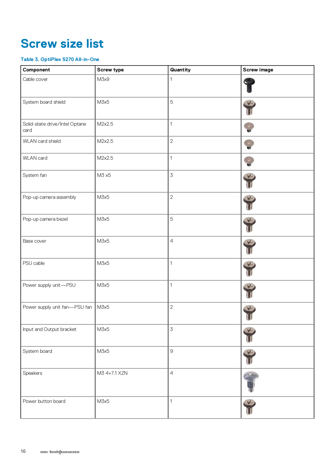
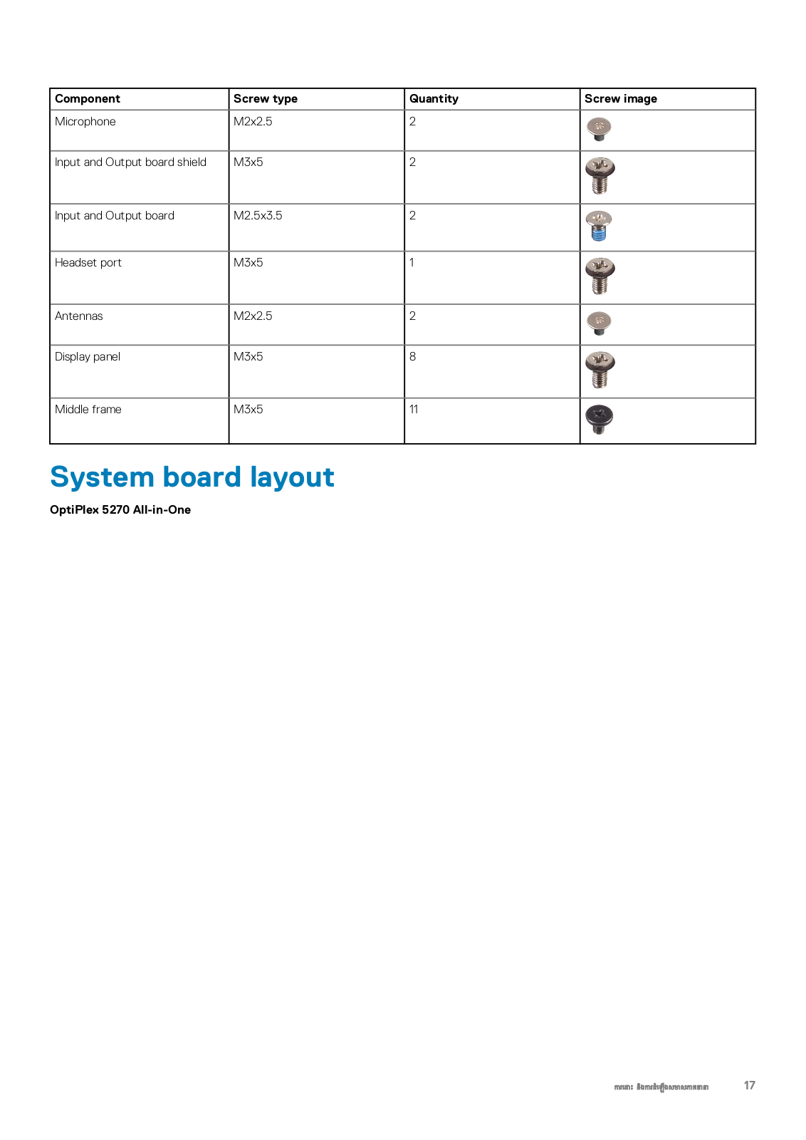
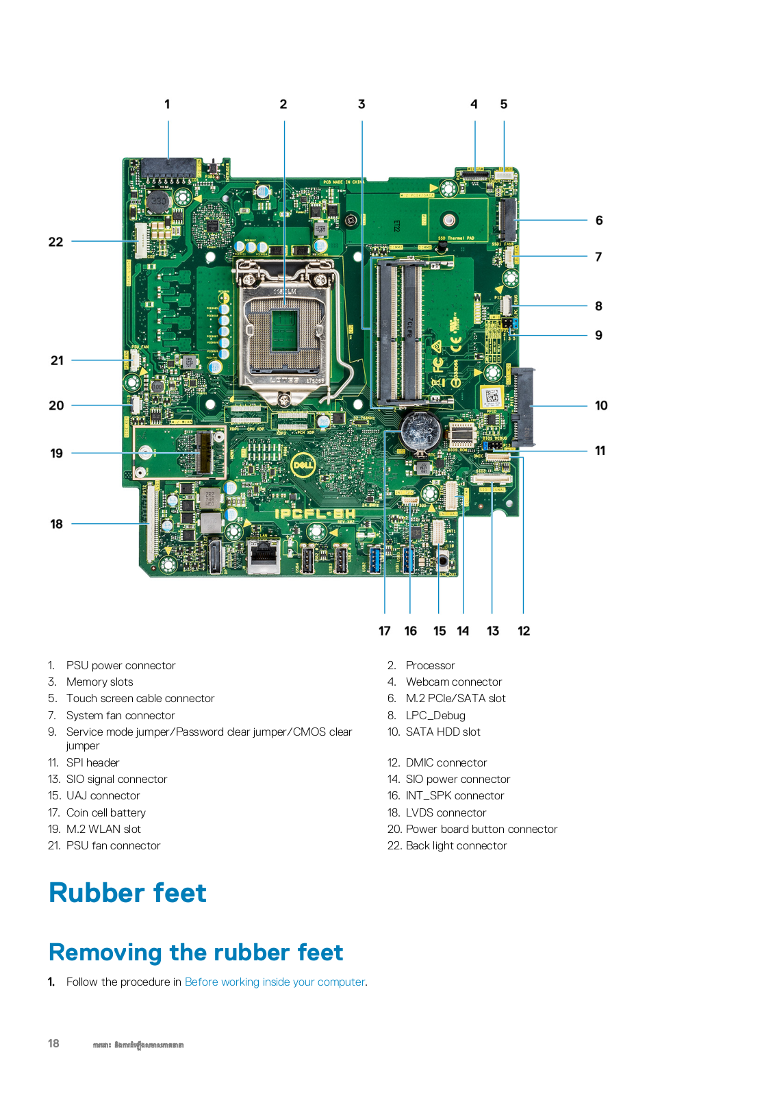
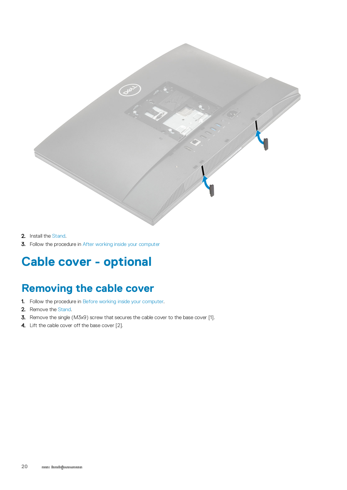
OptiPlex 5270
57
OptiPlex 5270 All-in-One
OptiPlex 5490 All-In-One
OptiPlex 580
87
OptiPlex 580 Desktop
28
OptiPlex 580 Mini-Tower
28
OptiPlex 580 Small Form Factor
27
OptiPlex 7010
117
OptiPlex 7020
70
OptiPlex 7040
90
Optiplex 7040M
OptiPlex 7050
92
Optiplex 7050 Tower
OptiPlex 7060
193
Optiplex 7060 MFF
OptiPlex 7060 Micro
Optiplex 7060 MT
OptiPlex 7060 SFF
Optiplex 7070 Micro
OptiPlex 7070 MT
Optiplex 7070 Tower
2
OptiPlex 7070 Ultra
4
OptiPlex 7071
60
OptiPlex 7071 Tower
OptiPlex 7080 Tower
OptiPlex 7090 Ultra
3
OptiPlex 740
24
Optiplex 740MLK
OptiPlex 7440
43
OptiPlex 745
21
OptiPlex 7450
50
Optiplex 7450-8411
Optiplex 7450-8428
OptiPlex 7450 All-In-One
OptiPlex 745C
16
OptiPlex 7460
99
OptiPlex 7470
61
OptiPlex 7480
OptiPlex 7480 All-In-One
4
OptiPlex 755
40
OptiPlex 760
81
Optiplex 7760
OptiPlex 7760 All-in-One
2
OptiPlex 7770
54
OptiPlex 7770 All-in-One
OptiPlex 7780 All-In-One
OptiPlex 780
143
OptiPlex 780 Desktop
28
OptiPlex 780 Mini-Tower
26
OptiPlex 780 Small Form Factor
28
Loading...
Loading...
Nothing found
OptiPlex 5270
User Manual [de]
44 pgs
2.21 Mb
0
User Manual [es]
44 pgs
2.19 Mb
0
User Manual [de]
109 pgs
24.94 Mb
0
User Manual [sv]
109 pgs
24.93 Mb
0
User Manual [sk]
109 pgs
24.94 Mb
0
User Manual [in]
109 pgs
24.94 Mb
0
User Manual [da]
108 pgs
24.61 Mb
0
User Manual [cs]
109 pgs
24.94 Mb
0
User Manual [tr]
43 pgs
2.29 Mb
0
User Manual [pt]
109 pgs
24.94 Mb
0
User Manual [nl]
109 pgs
24.94 Mb
0
User Manual [kh]
109 pgs
24.98 Mb
0
User Manual [fr]
109 pgs
24.94 Mb
0
User Manual [ar]
109 pgs
25.09 Mb
0
User Manual [cr]
44 pgs
2.19 Mb
0
User Manual [ja]
109 pgs
25.35 Mb
0
User Manual [ru]
110 pgs
25.08 Mb
0
User Manual [sr]
109 pgs
24.95 Mb
0
User Manual [si]
109 pgs
24.94 Mb
0
User Manual [hu]
109 pgs
24.94 Mb
0
User Manual [no]
109 pgs
24.93 Mb
0
User Manual [ko]
109 pgs
25.2 Mb
0
User Manual [he]
109 pgs
25.06 Mb
0
User Manual
109 pgs
24.93 Mb
0
User Manual [zh]
109 pgs
25.5 Mb
0
User Manual [ro]
109 pgs
24.96 Mb
0
User Manual [po]
109 pgs
24.94 Mb
0
User Manual [gr]
110 pgs
25.12 Mb
0
User Manual [fi]
109 pgs
24.97 Mb
0
User Manual [zh]
41 pgs
2.81 Mb
0
User Manual
21 pgs
399.66 Kb
0
User Manual
43 pgs
2.18 Mb
0
User Manual [zh]
109 pgs
25.55 Mb
0
User Manual [pt]
109 pgs
24.94 Mb
0
User Manual [in]
109 pgs
24.93 Mb
0
User Manual [cr]
109 pgs
24.94 Mb
0
User Manual [sv]
44 pgs
2.19 Mb
0
User Manual [sr]
43 pgs
2.19 Mb
0
User Manual [si]
44 pgs
2.19 Mb
0
User Manual [sk]
44 pgs
2.2 Mb
0
User Manual [ru]
44 pgs
2.47 Mb
0
User Manual [pt]
44 pgs
2.19 Mb
0
User Manual [pt]
42 pgs
1.87 Mb
0
User Manual [po]
44 pgs
2.2 Mb
0
User Manual [nl]
44 pgs
2.19 Mb
0
User Manual [ko]
41 pgs
2.55 Mb
0
User Manual [ja]
43 pgs
2.59 Mb
0
User Manual [in]
43 pgs
2.19 Mb
0
User Manual [in]
44 pgs
2.19 Mb
0
User Manual [hu]
44 pgs
2.2 Mb
0
User Manual [he]
41 pgs
2.58 Mb
0
User Manual [fr]
44 pgs
2.21 Mb
0
User Manual [ar]
41 pgs
2.65 Mb
0
User Manual [zh]
41 pgs
2.77 Mb
0
User Manual [tr]
109 pgs
24.97 Mb
0
User Manual [es]
109 pgs
24.94 Mb
0
User Manual [no]
44 pgs
2.19 Mb
0
Table of contents
Loading...
Dell OptiPlex 5270 User Manual [kh]
...
Dell User Manual [kh]
Download
Loading...
+
79
hidden pages
Unhide
You need points to download manuals.
1 point = 1 manual.
You can buy points or you can get point for every manual you upload.
Buy points
Upload your manuals
 Loading...