

Page 1
Dell Global Solutions Engineering
Revision: A00
March 2012
vStart 100 and 200 Hyper-V Reference
Architecture
Release 1.3 for Dell 12th generation servers
Page 2

vStart 100 and 200 Reference Architecture
This document is for informational purposes only and may contain typographical errors and
technical inaccuracies. The content is provided as is, without express or implied warranties of any
kind.
© 2012 Dell Inc. All rights reserved. Dell and its affiliates cannot be responsible for errors or omissions
in typography or photography. Dell, the Dell logo, PowerConnect, EqualLogic, OpenManage, and
PowerEdge are trademarks of Dell Inc. Intel and Xeon are registered trademarks of Intel Corporation in
the U.S. and other countries. Microsoft, Windows, Hyper-V, Active Directory, and Windows Server are
either trademarks or registered trademarks of Microsoft Corporation in the United States and/or other
countries. Intel and Active Directory are registered trademarks of Intel Corporation. Other trademarks
and trade names may be used in this document to refer to either the entities claiming the marks and
names or their products. Dell disclaims proprietary interest in the marks and names of others.
March 2012| Rev A00
Dell Inc. ii
Page 3

vStart 100 and 200 Reference Architecture
Contents
1 Introduction ........................................................................................................... 1
2 Audience............................................................................................................... 1
3 Solution Overview ................................................................................................... 2
3.1 Product Overview ............................................................................................. 4
3.1.1 PowerEdge R720 for Hyper-V Cluster ................................................................... 4
3.1.2 EqualLogic PS6100 for iSCSI Storage .................................................................... 4
3.1.3 PowerEdge R620 Management Server .................................................................. 5
3.1.4 PowerConnect 7048 or 6248 for LAN and SAN Traffic ............................................... 5
4 Design Principles ..................................................................................................... 7
4.1 No Single Point of Failure .................................................................................... 7
4.2 Physical Separation of LAN and iSCSI SAN Traffic ....................................................... 7
4.3 Logical Separation of multiple LAN traffic types ........................................................ 7
4.4 Prerequisites and Datacenter Planning .................................................................... 7
5 Architecture .......................................................................................................... 8
5.1 Network Architecture Overview ............................................................................ 8
5.2 LAN Architecture ............................................................................................ 10
5.2.1 Traffic Isolation using VLANs ........................................................................... 10
5.3 SAN Architecture ............................................................................................ 11
5.3.1 Traffic Isolation using VLAN ............................................................................ 11
5.3.2 EqualLogic Storage Concepts ........................................................................... 11
5.3.3 Volume Size Considerations ............................................................................ 11
5.3.4 Storage Array RAID Considerations .................................................................... 12
5.4 Hyper-V Role and Failover Clustering Design ........................................................... 13
5.4.1 Roles and Features ....................................................................................... 13
5.5 Management Architecture ................................................................................. 13
5.5.1 Management on the LAN ................................................................................ 13
6 Scalability ........................................................................................................... 16
6.1 Adding new servers to the Hyper-V Cluster ............................................................ 16
6.2 Adding new storage to the EqualLogic group........................................................... 16
7 References .......................................................................................................... 17
Dell Inc. iii
Page 4

vStart 100 and 200 Reference Architecture
Tables
Table 1. Component Logical Groups ............................................................................... 4
Table 2. Traffic Type Summary ................................................................................... 10
Figures
Figure 1. vStart 100 Overview ....................................................................................... 2
Figure 2. vStart 200 Overview ....................................................................................... 3
Figure 3. vStart 100 and 200 Component Overview .............................................................. 6
Figure 4. vStart 200 Network Topology (Logical View) .......................................................... 9
Figure 5. EqualLogic Organizational Concepts .................................................................. 11
Figure 6. Management Overview (LAN) .......................................................................... 15
Dell Inc. iv
Page 5

vStart 100 and 200 Reference Architecture
1
1 Introduction
The vStart solution is a virtualization infrastructure solution that has been designed and validated by
Dell Engineering. It is delivered racked, cabled, and ready to be integrated into your datacenter. vStart
is offered as three configurations: vStart 501, 100 and 200.
The configurations include DellTM PowerEdgeTM R720 servers running Microsoft® Windows Server® 2008
R2 SP1 Datacenter Edition with Hyper-V® Role enabled, Dell EqualLogicTM PS6100 Series iSCSI storage,
Dell PowerConnectTM 7048 or 6248 switches, a Dell PowerEdge R620 server that manages the solution
by hosting Dell management tools and optional System Center Virtual Machine Manager 2008 R2.
The configurations also include Dell EqualLogic Host Integration Tools for Microsoft (HIT Kit) for
Windows Server 2008 R2. The two vStart configurations vary in the number of R720 servers and
EqualLogic PS6100 storage arrays to meet resource needs.
The following documents are provided to describe the various aspects of the solution. Contact your Dell
Sales or Services representative to get the latest revision of all the documents.
vStart 100 and vStart 200 Hyper-V Reference Architecture (this document) – Provides a
reference overview, including various components, and how the solution is delivered.
vStart 100 and vStart 200 Hyper-V Solution Overview – Provides a solution overview, including
various components, and how it is delivered.
vStart 100 and vStart 200 Hyper-V Solution Specification – Provides a detailed specification of
various components included in the solution.
vStart 100 and vStart 200 Hyper-V Solution Design Guide – Provides a detailed architectural
solution design.
2 Audience
This document provides an overview of the vStart solution. Customers, including CTOs and IT managers,
can use this document to understand the overview and scope of the solution.
IT administrators and managers can use this document to understand the solution architecture.
vStart 50 is covered by a separate set of documents.
Dell Inc. 1
Page 6
vStart 100 and 200 Reference Architecture
EqualLogic PS6100
PowerEdge R720
PowerEdge R620
Hyper-V Cluster
Management Server (SCVMM, OMSA, SAN HQ)
iSCSI Storage
PowerConnect 7048
SAN Traffic (iSCSI)
PowerConnect 7048
LAN Traffic (VM, Management, Live Migration)
Optional – Available with vStart 100
Storage Expansion
EqualLogic SAN HQ and Group Manager, OMSA, Out of Band,
Virtualization Cluster Management
Management and Monitoring
2 4 6 8 10 12 14 16 18 20 22 24
1 3 5 7 9 11 13 15 17 19 21 23
45 46 47 48
LNK ACT
Reset
Stack No.
MRPSFan
PWR
Status
COMBO PORTS
LNK ACT
26 28 30 32 34 36 38 40 42 44 46 48
25 27 29 31 33 35 37 39 41 43 45 47
2 4 6 8 10 12 14 16 18 20 22 24
1 3 5 7 9 11 13 15 17 19 21 23
45 46 47 48
LNK ACT
Reset
Stack No.
MRPSFan
PWR
Status
COMBO PORTS
LNK ACT
26 28 30 32 34 36 38 40 42 44 46 48
25 27 29 31 33 35 37 39 41 43 45 47
2 4 6 8 10 12 14 16 18 20 22 24
1 3 5 7 9 11 13 15 17 19 21 23
45 46 47 48
LNK ACT
Reset
Stack No.
MRPSFan
PWR
Status
COMBO PORTS
LNK ACT
26 28 30 32 34 36 38 40 42 44 46 48
25 27 29 31 33 35 37 39 41 43 45 47
2 4 6 8 10 12 14 16 18 20 22 24
1 3 5 7 9 11 13 15 17 19 21 23
45 46 47 48
LNK ACT
Reset
Stack No.
MRPSFan
PWR
Status
COMBO PORTS
LNK ACT
26 28 30 32 34 36 38 40 42 44 46 48
25 27 29 31 33 35 37 39 41 43 45 47
3 Solution Overview
The solution discussed in this whitepaper is powered by Dell PowerEdge servers, Dell EqualLogic iSCSI
storage, Dell PowerConnect networking, and Microsoft Windows Server 2008 R2 with SP1. The solution
implements Dell and Microsoft best practices, and EqualLogic SAN HeadQuarters (SAN HQ) and Group
Manager are included in the solution for storage array monitoring and management. The solution also
includes the rack, power distribution units (PDU), and an optional uninterruptible power supply (UPS),
KMM (Keyboard, Monitor, Mouse), and management server.
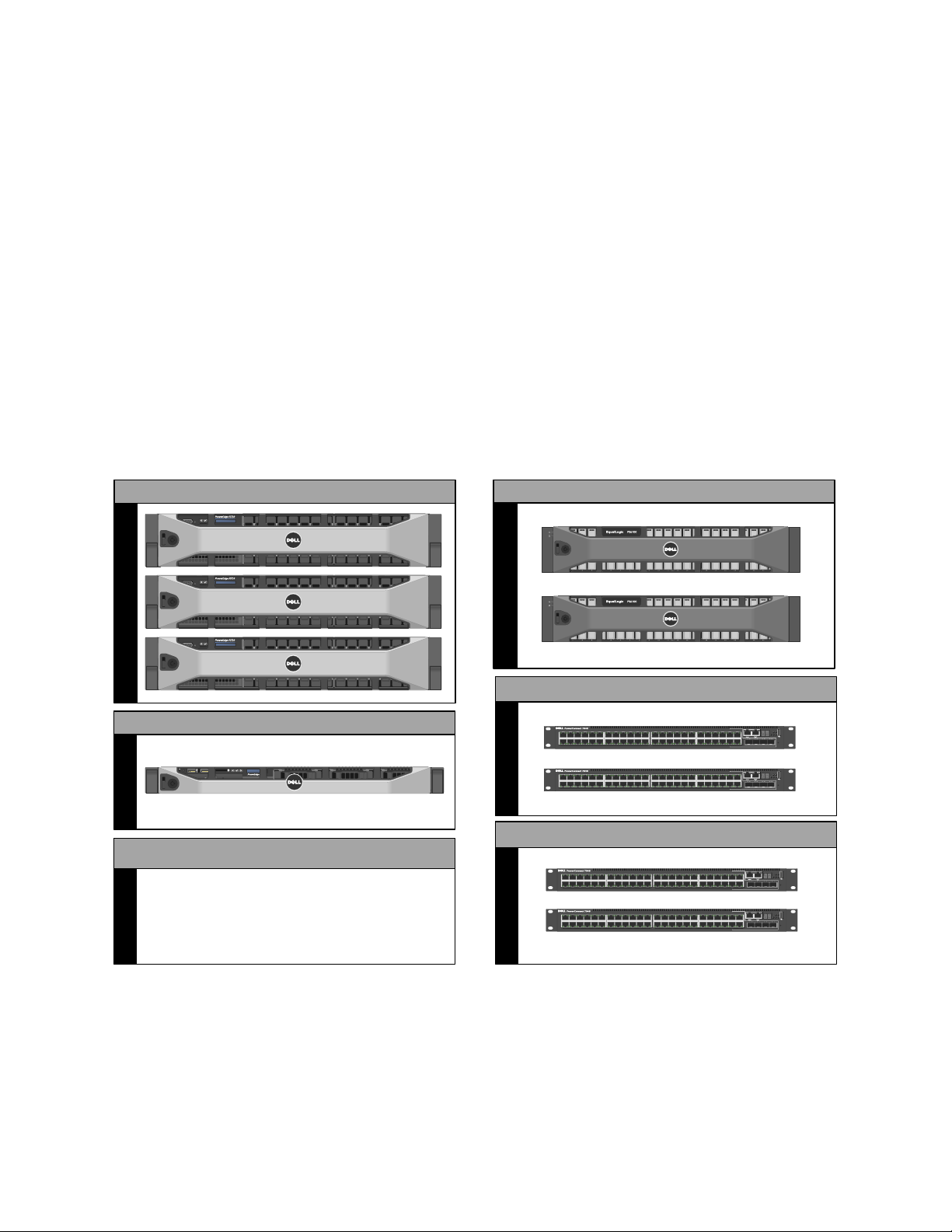
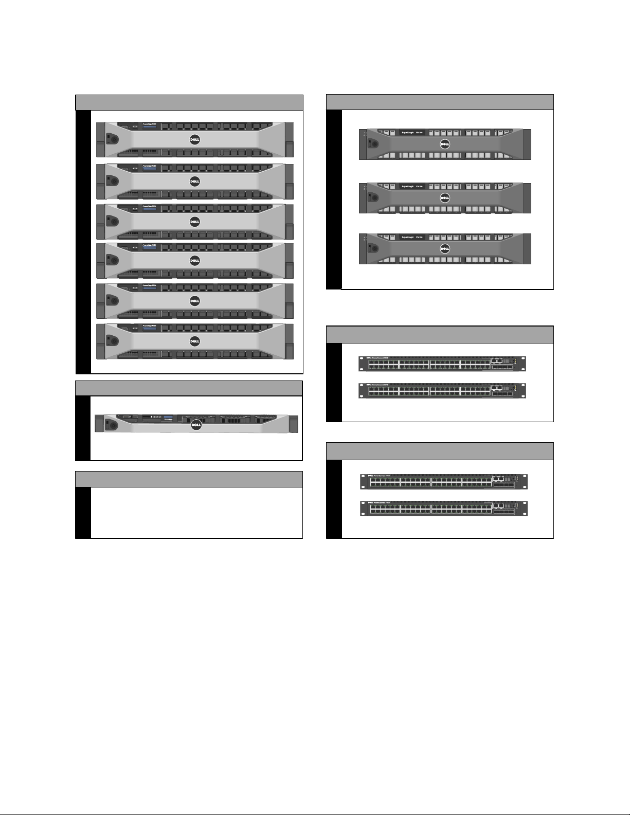
The solution is offered in two main configurations, vStart 100 and 200. The variations between the two
configurations are the number of PowerEdge R720 servers in the Hyper-V cluster and the number of
EqualLogic storage arrays. vStart 100 includes three PowerEdge R720 servers and one EqualLogic
storage array. vStart 200 includes six PowerEdge R720 servers and two EqualLogic storage arrays. An
additional optional storage array can be added to both configurations and the resulting configuration
will be referred to as vStart 100+ or vStart 200+ in the remainder of this document. Figure 1 and Figure
2 below provide a high-level overview of the components utilized in each of the configurations.
vStart 100 Overview Figure 1.
Dell Inc. 2
Page 7
vStart 100 and 200 Reference Architecture
Hyper-V Cluster
iSCSI Storage
EqualLogic SAN HQ and Group Manager, OMSA, Out of Band,
Virtualization Cluster Management
Management and Monitoring
PowerEdge R620
Management Server (SCVMM, OMSA, SAN HQ)
Optional – Available with vStart 200
Storage Expansion
PowerConnect 7048
SAN Traffic (iSCSI)
PowerConnect 7048
LAN Traffic (VM, Management, Live Migration)
2 4 6 8 10 12 14 16 18 20 22 24
1 3 5 7 9 11 13 15 17 19 21 23
45 46 47 48
LNK ACT
Reset
Stack No.
MRPSFan
PWR
Status
COMBO PORTS
LNK ACT
26 28 30 32 34 36 38 40 42 44 46 48
25 27 29 31 33 35 37 39 41 43 45 47
2 4 6 8 10 12 14 16 18 20 22 24
1 3 5 7 9 11 13 15 17 19 21 23
45 46 47 48
LNK ACT
Reset
Stack No.
MRPSFan
PWR
Status
COMBO PORTS
LNK ACT
26 28 30 32 34 36 38 40 42 44 46 48
25 27 29 31 33 35 37 39 41 43 45 47
2 4 6 8 10 12 14 16 18 20 22 24
1 3 5 7 9 11 13 15 17 19 21 23
45 46 47 48
LNK ACT
Reset
Stack No.
MRPSFan
PWR
Status
COMBO PORTS
LNK ACT
26 28 30 32 34 36 38 40 42 44 46 48
25 27 29 31 33 35 37 39 41 43 45 47
2 4 6 8 10 12 14 16 18 20 22 24
1 3 5 7 9 11 13 15 17 19 21 23
45 46 47 48
LNK ACT
Reset
Stack No.
MRPSFan
PWR
Status
COMBO PORTS
LNK ACT
26 28 30 32 34 36 38 40 42 44 46 48
25 27 29 31 33 35 37 39 41 43 45 47
PowerEdge R720
EqualLogic PS6100
Figure 2.
vStart 200 Overview
Dell Inc. 3
Page 8

vStart 100 and 200 Reference Architecture
Component
Description
Role
Hyper-V Cluster
PowerEdge R720 servers running
Windows Server 2008 R2
Datacenter Edition with SP1 and
Hyper-V role enabled
Host virtual machines (VMs)
iSCSI Storage
EqualLogic PS6100X with 24 x
600 Gigabyte (GB) 10,000 RPM
SAS Drives
Provide shared storage for the
Hyper-V cluster to host the VMs
Management Server
PowerEdge R620 server running
Microsoft ® Windows Server
®2008 R2 Standard Edition with
SP1
Host optional SCVMM 2008 R2,
and EqualLogic SAN HQ
LAN Traffic Switches
PowerConnect 7048 or 6248
switches
Support VM, Live Migration,
Management, Cluster and Outof-Band Management traffic
SAN Traffic Switches
PowerConnect 7048 or 6248
switches
Support iSCSI data
Table 1 below describes the solution components:
Component Logical Groups Table 1.
3.1 Product Overview
This section provides an overview of the components in the solution.
3.1.1 PowerEdge R720 for Hyper-V Cluster
The Dell PowerEdge R720 uses Intel® Xeon® E5-2600 series processors and Intel chipset architecture in
a 2U rack mount form factor. The R720 is a powerful general purpose platform with highly expandable
memory and I/O capabilities to match. Its extensive scalability and balanced design, allows it to handle
very demanding workloads. The server features two CPU sockets and 24 memory slots supporting 2, 4,
8, 16, or 32GB DIMMs to meet the memory demands of a virtualized infrastructure.
Energy-efficient design features include power-supply units sized appropriately for system
requirements, innovative system-level design efficiency, policy-driven power and thermal
management, and highly efficient standards-based Energy Smart components. For more information,
see the PowerEdge R720 Technical Guide.
3.1.2 EqualLogic PS6100 for iSCSI Storage
The Dell EqualLogic PS6100 is a virtualized iSCSI SAN that combines intelligence and automation with
fault tolerance to provide simplified administration, rapid deployment, enterprise performance and
reliability, and seamless scalability. The storage architecture delivers a self-optimizing SAN that is
simple to manage and has an all-inclusive software suite to help reduce Total Cost of Ownership (TCO).
In the vStart 100 and 200, the PS6100X uses 10,000 RPM Serial Attached SCSI (SAS) 2.5” form factor disk
drives to provide capacity and performance for a range of applications.
Dell Inc. 4
Page 9

vStart 100 and 200 Reference Architecture
With a 24 drive chassis full of 600GB SAS drives, the PS6100X array delivers 14.4 Terabyte (TB) of iSCSIbased storage built on fully-redundant, hot-swappable enterprise hardware. Scale out capacity and
performance is provided by adding additional arrays. Built-in software functionality includes automated
load balancing, snapshots and replication, multi-path I/O (MPIO), and consistency sets. SAN HQ is also
available for Multi-SAN historical performance monitoring.
Advanced data protection features such as Auto Replication and Auto-Snapshot Manager (ASM) also
come standard. ASM Microsoft Edition provides intelligent and consistent snapshots for the Windows
Server 2008 R2 SP1 hosts and the Hyper-V environment.
Multipath IO (MPIO) capabilities are enhanced by the EqualLogic HIT KIT. The HIT Kit configures MPIO
load balancing and redundant iSCSI initiator configurations for Windows Server-based hypervisor hosts.
For more information about the HIT Kit for Windows Servers, see Dell EqualLogic Host Software.
3.1.3 PowerEdge R620 Management Server
The Dell PowerEdge R620 uses Intel Xeon E5-2600 series processors and Intel chipset architecture in a
1U rack mount form factor. These servers support up to ten 2.5” drives and provide the option for an
LCD located in the front of the server for system health monitoring, alerting, and basic management
configuration. An AC power meter and ambient temperature thermometer are built into the server,
which can be monitored on this display without any software tools. The server features two CPU
sockets and 24 memory DIMM slots supporting 2, 4, 8, 16 or 32GB DIMMs.
Energy-efficient design features include power-supply units sized appropriately for system
requirements, innovative system-level design efficiency, policy-driven power and thermal
management, and highly efficient standards-based Energy Smart components. For more information,
see the PowerEdge R620 Technical Guide.
3.1.4 PowerConnect 7048 or 6248 for LAN and SAN Traffic
At the heart of the solutions network configuration are four Dell PowerConnect 7048 or 6248 switches.
These managed Layer 3 Gigabit Ethernet switches offer the enterprise-class level of performance
required for this configuration. The LAN switches use a stacked configuration that enables connection
redundancy and added bandwidth where required. Additionally, the 10Gb uplink enables design and
implementation flexibility needed by advanced users. LAN and SAN switches are physically and logically
separated per best practices to support security and network traffic segmentation. VLANs are
implemented to support solution management, security, and network traffic segmentation, and routing
is leveraged to provide flexible connectivity.
Dell Inc. 5
Page 10

vStart 100 and 200 Reference Architecture
01
02
03
04
05
06
07
08
09
10
11
12
13
14
15
16
17
18
19
20
21
22
23
24
25
26
27
28
29
30
31
32
33
34
35
36
37
38
39
40
41
42
01
02
03
04
05
06
07
08
09
10
11
12
13
14
15
16
17
18
19
20
21
22
23
24
25
26
27
28
29
30
31
32
33
34
35
36
37
38
39
40
41
42
01
02
03
04
05
06
07
08
09
10
11
12
13
14
15
16
17
18
19
20
21
22
23
24
25
26
27
28
29
30
31
32
33
34
35
36
37
38
39
40
41
42
01
02
03
04
05
06
07
08
09
10
11
12
13
14
15
16
17
18
19
20
21
22
23
24
25
26
27
28
29
30
31
32
33
34
35
36
37
38
39
40
41
42
SAN PowerConnect 7048
LAN PowerConnect 7048
PowerEdge R720
Hypervisor Cluster
17FP KMM
PE R620 Management
EqualLogic PS6100
Storage Group
Dell 3750W UPS
Equipment Shelf
RPS-720 RPS-720
Equipment Shelf
vStart100 vStart 200+
100V-240VAC, 4A
LOCATOR
RPS
DC IN 12V, 11A
STACKING MODULE
100V-240VAC, 4A
LOCATOR
RPS
DC IN 12V, 11A
100V-240VAC, 4A
LOCATOR
RPS
DC IN 12V, 11A
100V-240VAC, 4A
LOCATOR
RPS
DC IN 12V, 11A
STACKING MODULE
STACKING MODULE
STACKING MODULE
100V-240VAC, 4A
LOCATOR
RPS
DC IN 12V, 11A
STACKING MODULE
100V-240VAC, 4A
LOCATOR
RPS
DC IN 12V, 11A
100V-240VAC, 4A
LOCATOR
RPS
DC IN 12V, 11A
100V-240VAC, 4A
LOCATOR
RPS
DC IN 12V, 11A
STACKING MODULE
STACKING MODULE
STACKING MODULE
Figure 3.
vStart 100 and 200 Component Overview
Note: The vStart design can accommodate a single PS6100 chassis with 24x 3.5” hard drives. In vStart
100+, 200, or 200+ configurations, the second array can be ordered in either the 2.5” or 3.5” version of
the PS6100 chassis. There is an extra 2U of rack space open so that the factory can install and cable
the larger 3.5” drive 4U array. The default PS6100X with 24x 2.5” hard drives requires only 2U of rack
space, which is indicated in all of the diagrams in this document.
Dell Inc. 6
Page 11

vStart 100 and 200 Reference Architecture
4 Design Principles
This section covers the design principles, requirements, and solution capabilities incorporated in the
vStart solution architecture.
4.1 No Single Point of Failure
The solution is designed so that there is no single point of failure and redundancy is incorporated into
all mission critical components of the solution. Management applications are not architected with this
level of redundancy because the mission critical workloads will continue to operate in the event of a
management application failure. Network redundancy for the mission critical components is achieved
with redundant network interface controllers (NICs) and redundant switches. NIC teaming for LAN and
MPIO for SAN are used to provide failover across the redundant network interfaces.
For iSCSI storage, redundancy is achieved with redundant NICs, switches, and storage controllers. For
both network and iSCSI traffic, the redundant NICs are selected in such a way that they are mapped
across the rack Network Daughter Card (rNDC) and add-in controllers to avoid any single point of
failure. Hyper-V High Availability (HA) is provided by Windows Server 2008 R2 Failover Clustering. The
solution also includes redundant power supplies connected to separate PDUs.
4.2 Physical Separation of LAN and iSCSI SAN Traffic
Dedicated NICs and switches are provided for iSCSI storage traffic to isolate the storage traffic from
LAN traffic. This helps to minimize network latency for storage I/O operations.
4.3 Logical Separation of multiple LAN traffic types
Virtual Local Area Networks (VLANs) are used to provide security and logical separation of various
traffic types required for virtualization.
4.4 Prerequisites and Datacenter Planning
To support either of the configurations, the following components are required to be present in the
customer environment:
Active Directory® (AD) Domain Services (AD DS) – An AD DS domain must be available on the
network. The Hyper-V hosts will be joined to an existing or new domain. Cluster Services also
require AD DS. Optional management solutions like SCVMM require AD DS; however, this aspect
is out of scope for this paper. Consult with your Dell Sales and Services representatives for
more details.
Domain Name Server (DNS) – DNS must be available on the management network.
Network Time Protocol (NTP) Server - NTP is recommended on the management network.
Sufficient power to support a vStart 100 or 200 must be present. Detailed power, weight, and
cooling requirements for the datacenter are defined in the vStart 100 and 200 Hyper-V Solution
Specifications document.
Switch Connectivity – The network architecture supports uplinks into the existing switches in
the datacenter. The uplink recommendations are discussed in Section 5.1, Network
Architecture.
Dell Inc. 7
Page 12

vStart 100 and 200 Reference Architecture
Optional) Database to support SCVMM - For a list of supported databases refer to the SCVMM
Database Systems Requirements, or the Operations Manager 2007 R2 Supported Configurations.
o If IT Administrators wish to install SCVMM on the R620 Management Server or as a VM,
then a route must exist between the Management Server (physical or as a VM) and the
database for SCVMM.
o The database is assumed to have maintenance and backup configured as per the
business needs of the customer.
5 Architecture
The architecture discussed in this section will focus on the vStart 100 and the vStart 200 solutions.
5.1 Network Architecture Overview
Hyper-V network traffic in this solution is comprised of five distinct types: Virtual Machine (VM),
Management, Live Migration, Cluster Private, and iSCSI. In addition, support for Out-of-Band
Management (OOB) is included. Two separate networks are created to support different traffic types:
LAN - This network supports management, VM, Live Migration, Cluster Private, and out-of-band
management. In addition, uplinks to core infrastructure provide connectivity to the solution
support services (AD, DNS, NTP, and database for management applications).
SAN – This network supports iSCSI data. Uplinks are supported to connect into an existing iSCSI
network; however, these uplinks are not required for full solution functionality. SAN switch
out-of-band management also occurs on this network.
Figure 4 shown below depicts the vStart 200 logical LAN and SAN network architecture.
Dell Inc. 8
Page 13

vStart 100 and 200 Reference Architecture
LAN (PowerConnect 7048)
SAN (PowerConnect 7048)
Core Network
iSCSI Network
Hyper-V Cluster
PowerEdge R620
Management Server
iSCSI Storage
EqualLogic PS6100
Solution Support Services
AD/DNS
Database Server
Legend
Stacking Link
1Gb LAN
1Gb SAN
Out-Of-Band Mgmt
10Gb ISL
PowerEdge R720
NTP
2 4 6 8 10 12 14 16 18 20 22 24
1 3 5 7 9 11 13 15 17 19 21 23
45 46 47 48
LNK ACT
Reset
Stack No.
MRPSFan
PWR
Status
COMBO PORTS
LNK ACT
26 28 30 32 34 36 38 40 42 44 46 48
25 27 29 31 33 35 37 39 41 43 45 47
2 4 6 8 10 12 14 16 18 20 22 24
1 3 5 7 9 11 13 15 17 19 21 23
45 46 47 48
LNK ACT
Reset
Stack No.
MRPSFan
PWR
Status
COMBO PORTS
LNK ACT
26 28 30 32 34 36 38 40 42 44 46 48
25 27 29 31 33 35 37 39 41 43 45 47
2 4 6 8 10 12 14 16 18 20 22 24
1 3 5 7 9 11 13 15 17 19 21 23
45 46 47 48
LNK ACT
Reset
Stack No.
MRPSFan
PWR
Status
COMBO PORTS
LNK ACT
26 28 30 32 34 36 38 40 42 44 46 48
25 27 29 31 33 35 37 39 41 43 45 47
2 4 6 8 10 12 14 16 18 20 22 24
1 3 5 7 9 11 13 15 17 19 21 23
45 46 47 48
LNK ACT
Reset
Stack No.
MRPSFan
PWR
Status
COMBO PORTS
LNK ACT
26 28 30 32 34 36 38 40 42 44 46 48
25 27 29 31 33 35 37 39 41 43 45 47
Figure 4.
vStart 200 Network Topology (Logical View)
Dell Inc. 9
Page 14

vStart 100 and 200 Reference Architecture
Traffic Type
Use
Management
Supports virtualization management traffic and communication between the
Hyper-V R2 servers in the cluster
Live Migration
Supports migration of VMs between Hyper-V Host servers in the cluster
VM
Supports communication between the VMs hosted on the cluster and
external systems
Cluster Private
Supports internal cluster network communication between the servers in
the cluster
Out-of-Band
Management
Supports configuration and monitoring of the servers through the iDRAC
management interface, storage arrays, and network switches
iSCSI Data
Supports iSCSI traffic between the servers and storage array(s). In addition,
traffic between the arrays is supported
The table below summarizes the use of each traffic type.
Traffic Type Summary Table 2.
5.2 LAN Architecture
The LAN includes two PowerConnect 7048 or 6248 switches which support VM, Management, Cluster
Private, Live Migration, and OOB traffic. These traffic types are logically separated through the use of
VLANs. The two switches are stacked together, which forms a single logical switch and provides a
48Gb link between the two PC6248 switches, or 64Gb between the two PC7048 switches. The solution
provides four 1Gb uplinks from each switch to link into an existing core network infrastructure. If the
core network infrastructure supports 10Gb Ethernet, then 10Gb uplink modules may be added to each
switch; however this option is beyond the scope of this document.
5.2.1 Traffic Isolation using VLANs
The traffic on the LAN is segregated into five VLANs; one VLAN each for, VM, Management, Live
Migration, Cluster Private, and OOB traffic. VLAN tagging is performed through switch tagging as well
as host level tagging.
Dell Inc. 10
Page 15

vStart 100 and 200 Reference Architecture
Group
Pool
Pool
Member Member Member
5.3 SAN Architecture
The SAN includes two PowerConnect 7048 or 6248 switches which support iSCSI data traffic. The two
switches are connected together with stacking modules in Ethernet mode configured as an inter-switch
link (ISL) Link Aggregation Group (LAG). In addition, the solution supports up to eight 1Gb uplinks from
each switch to link into an existing core iSCSI network infrastructure. These uplinks are optional. If
required, 10Gb uplink modules may be added to each switch; however these options are beyond the
scope of this document.
5.3.1 Traffic Isolation using VLAN
The traffic for the SAN is also segregated into its own VLAN. This facilitates isolation from the default
VLAN and gives a separation between SAN traffic and any other traffic that it may come across if the
SAN is uplinked to a LAN or extended to another SAN for replication.
5.3.2 EqualLogic Storage Concepts
Each EqualLogic array (or member) is assigned to a particular group. Groups help in simplifying
management by enabling management of all members in a group from a single interface. Each group
contains one or more storage pools. Each pool must contain one or more members and each member is
associated with only one storage pool. Figure 5 shows an example of a group with three members
distributed across two pools.
EqualLogic Organizational Concepts Figure 5.
The iSCSI volumes are created at the pool level. In the case where multiple members are placed in a
single pool, the data is distributed amongst the members of the pool. With data being distributed over
a larger number of disks, the potential performance of iSCSI volumes within the pool is increased with
each member added.
For more information, consult with your Dell Sales and Services representatives for planning out and
designing an EqualLogic storage solution. Also, refer to the white paper, Using Tiered Storage in a PS
Series SAN, available at http://www.equallogic.com/WorkArea/DownloadAsset.aspx?id=5239.
5.3.3 Volume Size Considerations
Volumes are created in the storage pools. Volume sizes depend on the customer environment and the
type of workloads. Volumes must be sized to accommodate not only the VM virtual hard drive, but also
Dell Inc. 11
Page 16

vStart 100 and 200 Reference Architecture
the size of the virtual memory of the VM and additional capacity for any snapshots of the VM.
Depending on the environment, one may decide to create multiple ~500 GB volumes with multiple VMs.
It is important to include space for the guest operating system memory cache, snapshots, and VM
configuration files when sizing these volumes. Additionally, one can configure thin-provisioned volumes
to grow on demand only when additional storage is needed for those volumes. Thin provisioning can
increase the efficiency of storage utilization.
With each volume created and presented to the servers, additional iSCSI sessions are initiated. When
planning the solution, it is important to understand that group and pool limits exist for the number of
simultaneous iSCSI sessions. For more information, refer to the current EqualLogic Firmware (FW)
Release Notes. FW Release Notes are available at the EqualLogic Support site
https://support.equallogic.com/secure/login.aspx.
5.3.4 Storage Array RAID Considerations
The storage array RAID configuration is highly dependent on the workload in your virtual environment.
The EqualLogic PS series storage arrays support four RAID types: RAID 5, RAID 6, RAID 10, and RAID 50.
The RAID configuration will depend on workloads and customer requirements. In general, RAID 10
provides the best performance at the expense of storage capacity.
RAID 10 generally provides better performance in random I/O situations, and requires additional
overhead in the case of a drive failure scenario. RAID 50 generally provides more usable storage, but
has less performance than RAID 10. RAID 5 provides the most storage capacity at the expense of lower
performance and availability than RAID 10. RAID 6 provides better data protection than RAID 5 or 50.
For more information on configuring RAID in EqualLogic, refer to the white paper, How to Select the
Correct RAID for an EqualLogic SAN, available at
http://www.EqualLogic.com/resourcecenter/assetview.aspx?id=8071.
Dell Inc. 12
Page 17

vStart 100 and 200 Reference Architecture
5.4 Hyper-V Role and Failover Clustering Design
5.4.1 Roles and Features
The Hyper-V role is required on the Windows Server 2008 R2 Datacenter host. The role enables features
such as creation, starting, and stopping of VM.
Failover Clustering is a feature that, when combined with the Hyper-V role provides fault tolerance at
the server level and enables features like Live Migration and VM failover.
More information on setting up Failover Clusters for Hyper-V can be found on Microsoft TechNet in
Hyper-V: Using Hyper-V and Failover Clustering available at http://technet.microsoft.com/en-
us/library/cc732181(WS.10).aspx .
Cluster Shared Volumes (CSV) is implemented on the Hyper-V cluster to allow multiple virtual machines
to utilize the same volume and migrate to any host in the cluster. The Live Migration feature of
Windows Server 2008 R2 allows movement of a virtual machine from one host to another without
perceivable downtime. For more information on configuring CSV and the network for live migration see
Hyper-V: Using Live Migration with Cluster Shared Volumes in Windows Server 2008 R2 available at:
http://technet.microsoft.com/en-us/library/dd446679(WS.10).aspx
5.5 Management Architecture
The management architecture of the vStart configurations includes hardware and software components
that will manage all components of the vStart architecture. They can be found on the R620 server or on
VMs running on the R620.
5.5.1 Management on the LAN
The management traffic on the LAN includes:
Out–of-band server management through the iDRAC7 Enterprise
Server management through Dell OpenManage Server Administrator
Hyper-V and Cluster Manager
LAN switch management through CLI or web browser
EqualLogic array management through CLI or web browser
EqualLogic array monitoring with SAN HQ
Virtualization Management with SCVMM
Server Out-of-Band Management: The PowerEdge R720 servers and the PowerEdge R620 can be
managed directly by connecting to the iDRAC7 SSH or web interface. In addition, the iDRAC7 supports
remote KVM through a virtual console.
Dell OpenManage Server Administrator (OMSA): OMSA provides server hardware data to the host.
Information presented includes fan speeds, operating temperature, and various other heath monitors.
For more information about OMSA, refer to the Dell TechCenter at
http://www.delltechcenter.com/page/OpenManage+Server+Administrator+-+OMSA .
Hyper-V Cluster Management: Management of the Hyper-V hosts may optionally be performed
directly with SCVMM 2008 R2, but can also be performed by connecting to each server through the
Dell Inc. 13
Page 18

vStart 100 and 200 Reference Architecture
Hyper-V Manager that can be run from the R620 Management Server or VM. Server Manager can also be
utilized to access Hyper-V Manager, while the cluster is managed from the Failover Cluster Manager.
LAN and SAN Switch Management: Management of the LAN and SAN switches can be performed
through a web browser, serial cable, or telnet.
EqualLogic Array Management: The EqualLogic arrays are managed through the EqualLogic Group
Manager Web interface or through the SSH console, which can be accessed from the management
server. Administrator primary tasks within Group Manager include configuration and troubleshooting of
the arrays.
EqualLogic Array Monitoring: SAN HQ is installed on the management server to provide current
performance monitoring and historical statistics. Group Manager can also be used for array monitoring.
A logical overview of the LAN management architecture is shown in Figure 6. Notice that the PS6100
arrays are managed via the dedicated management ports that are connected to the LAN switches.
Dell Inc. 14
Page 19

vStart 100 and 200 Reference Architecture
LAN (PowerConnect 7048)
Hyper-V Cluster
PowerEdge R620
Management Server (SCVMM, OMSA, SAN HQ)
EqualLogic PS6100
Solution Support Services
AD/DNS
Database
For Management Server
Legend
1Gb LAN
Out-Of-Band Mgmt
PowerEdge R720
NTP
Core Network
iSCSI Storage
2 4 6 8 10 12 14 16 18 20 22 24
1 3 5 7 9 11 13 15 17 19 21 23
45 46 47 48
LNK ACT
Reset
Stack No.
MRPSFan
PWR
Status
COMBO PORTS
LNK ACT
26 28 30 32 34 36 38 40 42 44 46 48
25 27 29 31 33 35 37 39 41 43 45 47
2 4 6 8 10 12 14 16 18 20 22 24
1 3 5 7 9 11 13 15 17 19 21 23
45 46 47 48
LNK ACT
Reset
Stack No.
MRPSFan
PWR
Status
COMBO PORTS
LNK ACT
26 28 30 32 34 36 38 40 42 44 46 48
25 27 29 31 33 35 37 39 41 43 45 47
Figure 6.
Management Overview (LAN)
Dell Inc. 15
Page 20

vStart 100 and 200 Reference Architecture
6 Scalability
When adding additional servers or storage to the rack, power, rack space, weight, and cooling
requirements must be taken into account. The power limits of PDUs and UPSs must be understood
prior to installing a new system.
Switch ports on both the LAN and SAN switches are available for expansion. Those ports must be
enabled and configured to support the new servers and/or storage arrays.
6.1 Adding new servers to the Hyper-V Cluster
If additional VMs will be deployed that will exceed current resource capabilities, or the Hyper-V cluster
has reached its acceptable maximum (CPU and memory) resource utilization, then additional servers
can be added to the cluster up to a maximum of 16 nodes depending on the rack and datacenter
capacity. See the Limitations for using Hyper-V and Failover Clustering section for more information at
this link http://technet.microsoft.com/en-us/library/cc732181(WS.10).aspx
Previously created iSCSI volumes on the EqualLogic array may require modifications to the access
controls to grant access to the newly added servers.
When adding servers to a Hyper-V cluster, it is recommended that the configuration be identical to the
other systems in the cluster. If this is not achievable, there may be restrictions on certain actions,
such as Live Migration between the differing systems. To understand Live Migration compatibility
requirements, refer to the Microsoft whitepaper, Windows Server 2008 R2 Hyper-V Live Migration
Overview and Architecture, available at
http://www.microsoft.com/download/en/details.aspx?id=12601.
6.2 Adding new storage to the EqualLogic group
New EqualLogic arrays can be added to the existing EqualLogic group. As each new array is added to
the storage group, the storage capacity and performance, in terms of both bandwidth and IOPS, are
increased. This increased capacity can be utilized without downtime. When a new array is added to an
existing pool, the existing data will automatically be distributed to the newly added array.
If EqualLogic thin provisioning was utilized and virtual capacity allocated is nearing the limit of physical
capacity, adding an additional storage array to the constrained pool will address this issue. The impact
to the total iSCSI session count for the EqualLogic group and pools must be also be understood when
adding either new servers or EqualLogic arrays.
Dell Inc. 16
Page 21

vStart 100 and 200 Reference Architecture
7 References
Microsoft references:
Windows Server 2008 R2 Datacenter
http://www.microsoft.com/en-us/server-cloud/windows-server/2008-r2-datacenter.aspx
Install the Hyper-V Role on a Full Installation of Windows Server 2008 R2
http://social.technet.microsoft.com/wiki/contents/articles/steps-to-install-hyper-v-role-onserver-2008r2.aspx
Failover Clusters in Windows Server 2008 R2
http://technet.microsoft.com/en-us/library/ff182326(WS.10).aspx
EqualLogic references:
Dell EqualLogic PS Series Architecture Whitepaper
http://www.dell.com/downloads/global/products/pvaul/en/dell_equallogic_architecture.pdf
Host Integration Tools for Windows
http://www.dell.com/downloads/global/products/pvaul/en/equallogic-host-software.pdf
How to Select the Correct RAID for an EqualLogic SAN
http://www.equallogic.com/resourcecenter/assetview.aspx?id=8071
Using Tiered Storage in a PS Series SAN
http://www.equallogic.com/resourcecenter/assetview.aspx?id=5239
Monitoring your PS Series SAN with SAN HQ
http://www.equallogic.com/resourcecenter/assetview.aspx?id=8749
Dell Inc. 17
 Loading...