

Dell M910 User Manual
PowerEdge M910
Name
Technical Guide
The M910 is ideal for
the demanding
applications at the
core of most data
centers, such as
large databases,
virtualization and
messaging
infrastructure.

Dell
Dell, PowerEdge, EqualLogic, PowerVault, OpenManage, and ReadyRails are trademarks of Dell, Inc.
Citrix® and XenServer™ are trademarks of Citrix Systems, Inc. and/or one or more of its subsidiaries,
and may be registered in the United States Patent and Trademark Office and in other countries.
Intel, Xeon, and Speedstep are registered trademarks and MMX and Core are trademarks of Intel
Corporation in the U.S. and other countries. HP and COMPAQ are trademarks of Hewlett-Packard
Company. Broadcom is a registered trademark and NetXtreme is a trademark of Broadcom
Corporation and/or its affiliates in the United States, certain other countries and/or the EU.
CommVault Galaxy and Simpana are registered trademarks of CommVault Systems, Inc. InfiniBand is
a registered trademark and service mark of the InfiniBand Trade Association. Matrox is a registered
trademark of Matrox Electronic Systems Ltd. Microsoft, Windows, Windows Server, SQL Server, and
BitLocker, and Hyper-V are either registered trademarks or trademarks of Microsoft Corporation in
the United States and/or other countries. Mellanox is a registered trademark of Mellanox
Technologies, Inc. and ConnectX, InfiniBlast, InfiniBridge, InfiniHost, InfiniRISC, InfiniScale, and
InfiniPCI are trademarks of Mellanox Technologies, Inc. Novell is a registered trademarks of Novell,
Inc., in the United States and other countries. PCI Express is a registered trademark of PCI-SIG. Red
Hat is a registered trademark of Red Hat, Inc. in the United States and other countries. Linux is a
registered trademark of Linus Torvalds. Symantec and Backup Exec are trademarks owned by
Symantec Corporation or its affiliates in the U.S. and other countries. QLogic and PathScale are
registered trademarks of Qlogic Corporation. VMware is a registered trademark and vSphere is a
trademark of VMware, Inc. in the United States and/or other jurisdictions. vRanger, vFoglight,
vConverter, Vizioncore vOptimizer, and Vizioncore vEssentials are trademarks of Vizioncore Inc.
Other trademarks and trade names may be used in this document to refer to either the entities
claiming the marks and names or their products. Dell disclaims proprietary interest in the marks and
names of others.
©Copyright 2010 Dell Inc. All rights reserved. Reproduction or translation of any part of this work
beyond that permitted by U.S. copyright laws without the written permission of Dell Inc. is unlawful
and strictly forbidden.
Revision 1 September 2010
Dell PowerEdge M910 Technical Guide 1

Dell
Table of Contents
1 Product Comparison ........................................................................................... 5
1.1 Overview .................................................................................................. 5
1.2 Product Comparison ..................................................................................... 6
2 New Technologies .............................................................................................. 8
2.1 Overview .................................................................................................. 8
2.2 Detailed Information .................................................................................... 8
2.2.1 Intel Xeon Processors .............................................................................. 8
2.2.2 Intel 7500 Chipset .................................................................................. 8
2.2.3 FlexMem Bridge .................................................................................... 8
2.2.4 IO Hub (IOH) with Intel QuickPath Architecture ............................................... 8
2.2.5 DDR3 Memory ....................................................................................... 8
2.2.6 PCI Express Generation 2 ......................................................................... 9
2.2.7 Internal Redundant SD Module ................................................................... 9
2.2.8 iDRAC6 Express ..................................................................................... 9
3 System Information .......................................................................................... 10
3.1 Overview ................................................................................................ 10
3.2 Product Features Summary ........................................................................... 10
4 Mechanical .................................................................................................... 12
4.1 Overview ................................................................................................ 12
4.2 Module Dimensions and Weight ...................................................................... 12
4.3 Internal Module ......................................................................................... 12
4.4 Security .................................................................................................. 13
4.5 Cover Latch ............................................................................................. 13
4.6 TPM (Trusted Platform Module) ...................................................................... 13
4.7 Power Off Security ..................................................................................... 14
4.8 USB Key .................................................................................................. 14
4.9 Battery ................................................................................................... 14
4.10 Field Replaceable Units (FRU)........................................................................ 14
5 Operating, Thermal, and Acoustic ......................................................................... 15
5.1 Overview of Operating and Storage Conditions .................................................... 15
5.2 Acoustics ................................................................................................ 16
5.3 Thermal.................................................................................................. 17
5.4 Power Efficiency ....................................................................................... 17
6 Processors ..................................................................................................... 18
6.1 Overview ................................................................................................ 18
6.2 Features ................................................................................................. 18
6.3 Supported Processors .................................................................................. 19
6.4 Processor Configurations .............................................................................. 19
6.5 FlexMem Bridge ........................................................................................ 19
7 Memory ........................................................................................................ 21
7.1 Overview ................................................................................................ 21
7.2 DIMMs Supported ....................................................................................... 22
7.3 Slots /Risers ............................................................................................. 22
7.4 Intel 7500 Scalable Memory Buffer (SMB) ........................................................... 22
7.5 Memory RAS Support ................................................................................... 22
7.5.1 Sparing ............................................................................................. 22
7.5.2 Mirroring ........................................................................................... 23
7.5.3 Supported Memory Configurations ............................................................. 24
Dell PowerEdge M910 Technical Guide 2

Dell
8 Chipset ........................................................................................................ 25
8.1 Intel 7500 I/O Hub (IOH) .............................................................................. 25
8.2 IOH QuickPath Interconnect (QPI) ................................................................... 25
8.3 PCI EXPRESS GENERATION 2 .......................................................................... 25
8.4 Direct Media Interface (DMI) ......................................................................... 25
8.5 Intel I/O Controller Hub 10 (ICH10) ................................................................. 25
8.6 PCI Express Mezzanine Connectors .................................................................. 26
9 BIOS ............................................................................................................ 27
9.1 Overview ................................................................................................ 27
9.2 Supported ACPI States ................................................................................. 27
10 Embedded Gigabit Ethernet Controllers on Motherboard (LOM) ...................................... 28
11 I/O Mezzanine Card Options ................................................................................ 29
11.1 Overview ................................................................................................ 29
11.2 Options .................................................................................................. 29
12 Storage ........................................................................................................ 30
12.1 Drives .................................................................................................... 30
12.2 Hard Disk Drive Carriers ............................................................................... 30
12.3 Empty Drive Bays ....................................................................................... 30
12.4 Diskless Configuration Support ....................................................................... 30
12.5 RAID Configurations .................................................................................... 31
12.6 Storage Controllers .................................................................................... 31
12.6.1 SATA Repeater .................................................................................... 31
12.6.2 PERC6/i ............................................................................................ 32
12.6.3 PERC H200 ......................................................................................... 32
12.6.4 PERC H700 ......................................................................................... 32
12.7 LED Indicators .......................................................................................... 32
12.8 Optical Drives ........................................................................................... 32
13 Video (PCI Video) ............................................................................................ 33
14 Rack Information ............................................................................................. 34
15 Operating Systems ........................................................................................... 35
16 Virtualization ................................................................................................. 36
16.1 Overview ................................................................................................ 36
16.2 Advanced Infrastructure Manager by Scalent ...................................................... 36
16.3 Vizioncore ............................................................................................... 37
17 Systems Management ........................................................................................ 38
17.1 Overview ................................................................................................ 38
17.2 Server Management .................................................................................... 38
17.3 Embedded Server Management ...................................................................... 39
17.4 Lifecycle Controller and Unified Server Configurator ............................................ 39
17.5 The iDRAC6 Enterprise ................................................................................ 40
17.6 Chassis Management Controller (CMC) .............................................................. 41
18 Peripherals .................................................................................................... 42
18.1 USB peripherals ......................................................................................... 42
18.2 External Storage ........................................................................................ 42
Tables
Table 1. Product Comparisons ................................................................................. 6
Table 2. Product Features .................................................................................... 10
Table 3. Operating and Storage Conditions ................................................................ 15
Table 4. Typical Configuration Used in Testing ........................................................... 16
Dell PowerEdge M910 Technical Guide 3

Dell
Table 5. Processor Cache Sizes (Package LGA1567) ...................................................... 18
Table 6. Supported Processors ............................................................................... 19
Table 7. PowerEdge M910 Sparing and Mirroring .......................................................... 22
Table 8. Supported Memory Configurations ................................................................ 24
Table 9. RAID Configurations ................................................................................. 31
Table 10. Storage Controllers Supported on the M910 ..................................................... 31
Table 11. Supported Video Modes ............................................................................ 33
Table 12. Virtualization Software ............................................................................. 36
Table 13. Unified Server Configurator Features and Description......................................... 39
Table 14. Features List for BMC, iDrac, and vFlash ........................................................ 40
Table 15. Industry Standards and URLs ...................................................................... 43
Figures
Figure 1. M1000e ................................................................................................ 12
Figure 2. Internal Module View ............................................................................... 13
Figure 3. Diagram of FlexMem Bridge Routing.............................................................. 20
Figure 4. Memory Diagram .................................................................................... 21
Figure 5. PowerEdge M910 2P Mirroring ..................................................................... 23
Figure 6. M910 4P Mirroring ................................................................................... 23
Figure 7. 2.5‖ HDD Carrier .................................................................................... 30
Dell PowerEdge M910 Technical Guide 4

1 Product Comparison
1.1 Overview
The Dell™ PowerEdge™ M-Series blade servers are designed to help cut operating expenses through
energy efficiency, scalability, product flexibility, and efficient use of data center space.
The PowerEdge M910 provides significant performance and reliability in a scalable, full-height, foursocket blade server, allowing the deployment of large Enterprise-class applications as well as the
ability to support heavy virtualization or workload consolidation in maximum density.
When combined with Dell’s world-class storage, management, and support offerings, the result is a
total enterprise solution that can help you optimize your IT environment and expenses.
Powerful
The PowerEdge M910 was designed to meet the needs of nearly any IT infrastructure or environment.
Built with powerful Intel® Xeon® processor 7500 series and advanced systems management
capabilities, the M910 is ideal for the demanding applications at the core of most data centers, such
as large databases, virtualization, and messaging infrastructure.
Memory is a critical component for performance, especially for heavy virtualization and high-end
database needs. With this in mind, the PowerEdge M910 was designed with 32 DIMM slots allowing up
to 512GB of ECC DDR3 RAM to be supported, allowing these memory-intensive applications to have
ample resources at their disposal.
Scalable
Many servers may be able to take advantage of the large memory support that modern architectures
provide, but only Dell offers FlexMem Bridge technology, which allows the M910 to seamlessly scale
from 4GB to 512GB of DDR3 RAM in either two-socket or four-socket configurations. This patentpending technology allows Dell to deliver a unique platform that can seamlessly scale as customer
and application needs dictate, without having to ―rip and replace‖ existing server infrastructure.
In addition to allowing significant memory and processor scaling capabilities, the compact formfactor of Dell blades allows the ability to scale down the amount of space that your core application
servers require. By utilizing the PowerEdge M910, you can deploy up to eight next generation 4socket servers in only 10U of rack space, which is less than 1/3 of the space required using
traditional 4U four-socket rack servers.
Reliable
With the PowerEdge M910, Dell continues its unrelenting focus on reliability. The PowerEdge M910
utilizes the redundant power, cooling, and networking infrastructure provided by the Dell M1000e
Blade enclosure. The PowerEdge M910 itself incorporates improvements and features for maximum
protection against potential downtime, such as the ability to support three fully redundant fabrics
per blade and the inclusion of a dual-media redundant embedded hypervisor.
The PowerEdge M910 also utilizes Intel Xeon 7500 series processors which are designed to
automatically monitor, report, and recover from hardware errors in order to maintain data integrity
and keep mission-critical services online.
As with all Dell PowerEdge servers, the M910 is manufactured with our ―one-touch‖ factory build
process. This process is designed to ensure just one person is responsible for the entire server build,
resulting in greater quality control. In addition, every fully configured Dell server is tested (and retested) before it leaves the factory to ensure maximum reliability.

Dell
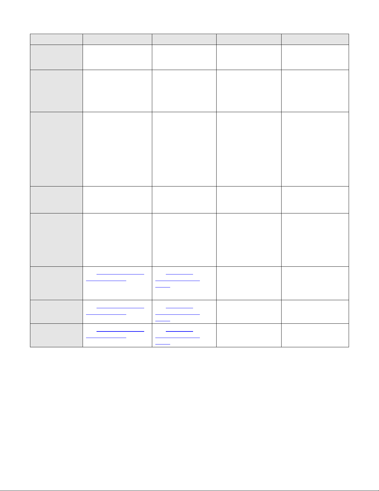
Feature /Spec
M910
M710
R810
R910
Processor
4 Socket
Intel® Xeon® processor
6500 and 7500 series
2 Socket
Intel® Xeon® processor
5500 series
4 Socket
Intel® Xeon® processor
6500 and 7500 series
2 or4 Socket
Intel® Xeon® 7500 Series
Front Side Bus
Four Intel® QuickPath
Interconnect (QPI) links
Two Intel® QuickPath
Interconnect (QPI)
links
Four Intel® QuickPath
Interconnect (QPI)
links
Up to 6.4 GT/s Intel®
QuickPath Interconnect
(QPI) links
# Proc Sockets
2/4 2 2/4
2/4/6
Max # Cores per
Socket
2S w/ up to16 cores
4S w/ up to 32 cores
Up to 4
2S w/ up to16 cores
4S w/ up to 32 cores
2S w/ up to16 cores
4S w/ up to 32 cores
L2/L3 Cache
L2 cache:1.5MB or 2MB
L3 cache: 12MB, 18MB or
24MB (shared)
4MB and 8MB
L2 cache:1.5MB or 2MB
L3 cache: 12MB, 18MB
or 24MB (shared)
L3 cache: 12MB, 18MB
or 24MB
Chipset
Intel® 7500
Intel® 5520
Intel® 7500
Intel® 7500
DIMMs
32 x DDR3
18 DDR3
32 x DDR3
64 x DDR3
Min/Max RAM
4GB–512GB
1GB–192GB
4GB–512GB
4GB – 1TB
Form Factor
Full Height Blade, Dual
Slot
Full Height Blade, Dual
Slot
2U Chassis, Rack
4U chassis, Rack
HD Bays (2.5”
only)
2 4 6
16
HD Types
SAS/SSD
SAS/SSD
SAS/SSD
SAS/SSD
Integrated
Standard HD
Controller
H200/H700 (factory
installed) and PERC6 as
custom kit
H200/H700
H200/H700
PERC6
H200/H700
Optional HD
Controller
H200/H700 Integrated
controller
(Battery backup for the
H700 and PERC6 options
only)
SAS6/iR PERC6i with
RAID battery
PERC H800 or 6Gbps
SAS
PERC H800 or 6Gbps
SAS
Availability
Hot-swap hard drives
Hot-swap redundant
power and cooling
ECC memory
Single Device Data
Correction (SDDC)
Supports memory
demand and patrol
scrubbing
High-availability failover
cluster support
Hot-swap hard drives
Hot-swap redundant
power and cooling
ECC memory
Single Device Data
Correction (SDDC)
Supports memory
demand and patrol
scrubbing
High-availability
failover cluster
support
Hot-swap hard drives
Hot-swap redundant
power and cooling
ECC memory
Single Device Data
Correction (SDDC)
Supports memory
demand and patrol
scrubbing
High-availability
failover cluster
support
Hot-swap hard drives
Hot-swap redundant
power and cooling
ECC memory
Single Device Data
Correction (SDDC)
supports memory
demand and patrol
scrubbing
High availability
Product documentation is available at support.dell.com. Information for the chassis can be found in
the PowerEdge M1000e Technical Guide.
1.2 Product Comparison
Table 1. Product Comparisons
Dell PowerEdge M910 Technical Guide 6
Dell
Feature /Spec
M910
M710
R810
R910
Server
Management
iDRAC6 Enterprise
CMC (on M1000e)
iDRAC6 Enterprise
(Both) standard
CMC (on M1000e)
iDRAC6 Express iDRAC6
Enterprise Optional
iDRAC6 Express iDRAC6
Enterprise Optional
Mezz Slots
4 x8 PCIe Mezzanine
Cards
1 x 4 and 3 x 8 PCIe
Mezzanine Cards
6 x PCIe
5 x 8
1 x 4
7 PCIe Gen2 slots
(2x4, 4 x8 + 1x16)
Optional: 10 PCI e Gen2
(6x4, 4x8)
Slot 5 is Gen1
NIC/LOM
4 x TOE – iSCSI offload
4 x TOE with optional
iSCSI offload
4 x LOM
(5709)
1GbE or 10Gp SFP+
embedded NIC options
4-port (4x1GbE)
embedded NIC
Broadcom 5709c
Or
4-port (2x10gb SPF+ &
2x1GbE) Embedded NIC
Broadcom 57711 +
Broadcom 5709c
USB
3 x External USB 2.0
ports at front bezel
1 x Internal USB port
3 x External USB 2.0
ports at front bezel
1 x Internal USB port
2 ports in the front
4 ports in the rear
2 in the rear
2 in the front
1
SD Card
2 x Internal SD slot
1 for Persistent Storage
1 for Lifecycle controller
on iDRAC
(can also be configured
as redundant SD cards RIPS)
1 x Internal SD slot
1 for Persistent
Storage 1 for Lifecycle
controller on iDRAC
2 x Internal SD slot
1 for Persistent
Storage 1 for Lifecycle
controller on iDRAC
2 x Internal SD slot
1 for Persistent Storage
1 for Lifecycle
controller on iDRAC
Power Supplies
See PowerEdge M1000e
Technical Guide
See PowerEdge
M1000e Technical
Guide
2 x 1100W
4 x 750w (Energy
Smart)
Or
4 x 1100W (High output)
Fans
See PowerEdge M1000e
Technical Guide
See PowerEdge
M1000e Technical
Guide
Redundant cooling
Redundant cooling
Chassis
See PowerEdge M1000e
Technical Guide
See PowerEdge
M1000e Technical
Guide
Rack
Rack
Dell PowerEdge M910 Technical Guide 7

Dell
2 New Technologies
2.1 Overview
The PowerEdge M910 server includes the following new features:
Intel Xeon Processor 7500 Series (4s) and Intel Xeon Processor 6500 Series (2s) 4-, 6-, and 8-
core processors
Intel 7500 Chipset
FlexMem Bridge
IO Hub (IOH) with Intel
DDR3 memory
PCI Express
Optional Redundant SD media for embedded hypervisor
iDRAC6 Express
®
Generation 2
2.2 Detailed Information
2.2.1 Intel Xeon Processors
The processor features up to eight-core processing to with maximize performance (expected up to
3.8x performance improvements) and performance/watt and significant energy efficiency
improvements for datacenter infrastructures and highly dense deployments. Additionally, the Intel
Xeon processor 6500 and 7500 series features the Intel® 64 Architecture for flexibility in 64-bit and
32-bit applications and operating systems.
®
QuickPath Architecture
2.2.2 Intel 7500 Chipset
See Section 8 for detailed information in the Intel 7500 chipset.
2.2.3 FlexMem Bridge
The PowerEdge M910 also introduces a new, Dell patent-pending, technology which will allow
flexibility in processor and memory scalability—FlexMem Bridge. The FlexMem Bridge allows the full
amount of addressable DIMMs on 4-Socket systems with Intel Xeon processor 7500 and 6500 series to
be accessed, even when only 2 of the processors are in place, in a completely passive solution (no
active components).
2.2.4 IO Hub (IOH) with Intel QuickPath Architecture
The Intel QuickPath Architecture consists of serial point-to-point interconnects for the processors
and the system IOH. The M910 has a total of eight QuickPath Interconnects (QPI) lines: six links
connecting the processors and two links connection processors 1 and 2 with the IOH.
2.2.5 DDR3 Memory
The M910 uses DDR3 memory which provides a high-performance, high-speed memory interface
capable of low latency response and high throughput. The M910 supports Registered ECC DDR3 DIMMs
(RDIMMs).
The DDR3 memory interface consists of 8 Intel Scalable Memory Buffers (SMBs), each or which has
two DDR3 memory channels. Each channel supports up to two RDIMMs for single/dual/quad rack. By
limiting to two DIMMs per DDR channel, the system can support quad-rank DIMMs at 1067MHz.
Dell PowerEdge M910 Technical Guide 8

Dell
2.2.6 PCI Express Generation 2
PCI Express is a serial point‐to‐point interconnect for I/O devices. PCIe Gen2 doubles the signaling bit
rate of each lane from 2.5 Gb/s to 5 Gb/s. Each of the PCIe Gen2 ports is backwards‐compatible with
Gen1 transfer rates.
2.2.7 Internal Redundant SD Module
The Internal SD Module is dedicated for an SD Flash Card with embedded Hypervisor for
virtualization. The SD Flash Card contains a bootable OS image for virtualized platforms.
The persistent storage solution on the M910 allows for redundant SD cards.
2.2.8 iDRAC6 Express
The iDRAC6 Express feature set is a managed persistent storage space for server provisioning data. It
consists of 1 GB flash and vFlash (an optional externally accessible SD card). vFlash offers the hotswap portability and increased storage capacity benefits of SD while still being managed by the
system.
Dell PowerEdge M910 Technical Guide 9
Dell
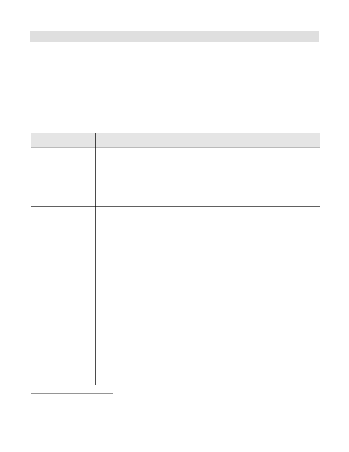
Feature
Dell™ PowerEdge™ M910
Processors
Up to Four Intel® Xeon® processor 7500 series Quad-, Six-, or Eight-Core; or,
Up to Two Intel® Xeon® processor 6500 series Quad-, Six-, or Eight-Core
Chipset
Intel® 7500
Memory1
1GB/2GB/4GB/8GB/16GB ECC DDR3
Support for up to 512GBs using 32 x 16GB DIMMs
Drive Bays
Two 2.5‖ SAS/Solid State hot-swappable drives
Storage1
Internal:
2.5‖ 6Gbs SAS (15K): 73GB, 146GB
2.5‖ 6Gbs SAS (10K): 146GB, 300GB
2.5‖ 6Gbs SAS (7.2K): 500GB
2.5‖ SSD: 50GB, 100GB
External:
Dell™ EqualLogic™ PS Series
Dell™ PowerVault™ MD Series & NX Series
Dell/EMC CX Series, AX Series & NS Series
RAID Controller
Options
PERC H200 Modular RAID Controller (6Gb/s)
PERC H700 Modular RAID Controller (6Gb/s) with 512MB battery-backed cache;
512MB, 1GB Non-Volatile battery-backed cache
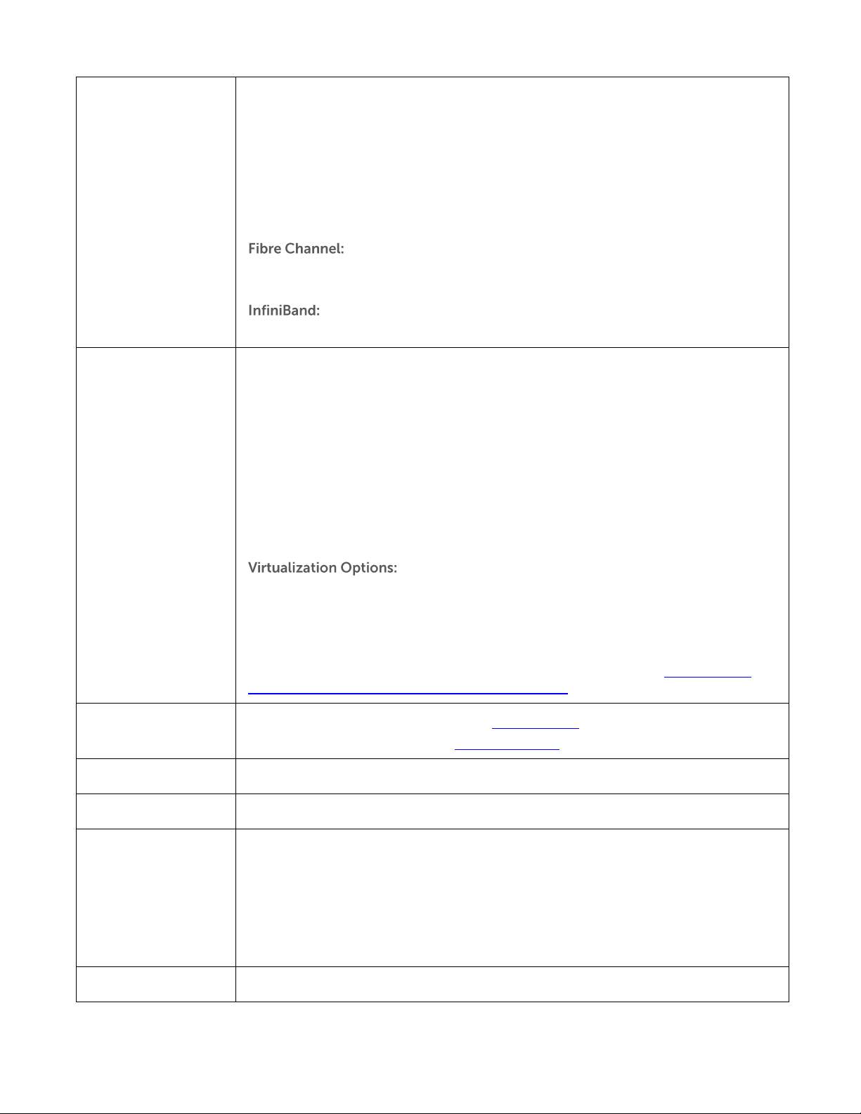
I/O Mezzanine Card
Options
Fully populated mezzanine card slots and switch modules will yield 3 highly
available, redundant I/O fabrics per blade.
1Gb & 10Gb Ethernet:
Broadcom® Dual-Port Gb Ethernet w/ TOE (BCM-5709S)
Intel® Quad-Port Gb Ethernet
Broadcom® Quad-Port Gb Ethernet (BCM-5709S)
1
3 System Information
3.1 Overview
The PowerEdge M910 is an innovative blade design that allows scaling from 2 to 4 sockets (no single
or 3 socket support) based on a new generation of Intel four-socket enhanced processors, RAM, and
management while still taking advantage of the M1000e chassis architecture. Along with the M1000e
chassis, the PowerEdge M910 server leads the industry in high speed, redundant IO throughput and
power efficiency with more RAM slots in the 2-socket space.
3.2 Product Features Summary
Table 2. Product Features
GB means 1 billion bytes and TB equals 1 trillion bytes; actual capacity varies with preloaded material and
operating environment and will be less.
Dell PowerEdge M910 Technical Guide 10
Dell
Intel® Dual-Port 10Gb Ethernet
Broadcom® Dual-Port 10Gb Ethernet (BCM-57711)
10Gb Enhanced Ethernet & Converged Network Adapters (CEE/DCB):
Intel® Dual-Port 10Gb Enhanced Ethernet (FcoE Ready for Future Enablement)
Emulex® Dual-Port Converged Network Adapter (OCM10102-F-M)—Supports CEE/DCB
10GbE + FCoE
Qlogic® Dual-Port Converged Network Adapter (QME8142)—Supports CEE/DCB 10GbE
+ FCoE
QLogic® Dual-Port FC8 Fibre Channel Host Bus Adapter (HBA) (QME2572)
Emulex® Dual-Port FC8 Fibre Channel Host Bus Adapter (HBA) (LPe1205-M)
Mellanox® Dual-Port ConnectX™ Quad Data Rate (QDR) InfiniBand
Operating Systems
Microsoft® Windows® Essential Business Server 2008
Microsoft® Windows Server® 2008 SP2, x86/x64 (x64 includes Hyper-V™)
Microsoft® Windows Server® 2008 R2, x86/x64 (includes Hyper-V™ v2)
Microsoft® Windows® HPC Server 2008
Novell® SUSE® Linux® Enterprise Server
Red Hat® Enterprise Linux®
Sun® Solaris™
For more information on the specific versions and additions, visit
www.dell.com/OSsupport.
Citrix® XenServer™
Microsoft® Hyper-V™ via Microsoft® Windows Server® 2008
VMware® vSphere™ 4.1 (including VMware ESX® 4.1 or VMware ESXi™ 4.1)
For more information on the specific versions and additions, visit the Operating
System Support Matrix for Dell PowerEdge Systems on Dell.com.
Featured Database
Applications
Microsoft® SQL Server® solutions (see Dell.com/SQL)
Oracle® database solutions (see Dell.com/Oracle)
Power Supply
Supplied by Dell™ M1000e Blade Chassis
Video
Matrox® G200eW w/ 8MB memory
Systems Management
BMC, IPMI2.0 compliant
Dell™ OpenManage™ featuring Dell Management Console
Unified Server Configurator
Lifecycle Controller
iDRAC6 Enterprise with optional vFlash
Remote Management: iDRAC6 Enterprise with optional vFlash
Embedded Hypervisor
Optional Dual-Media Redundant Hypervisor
Dell PowerEdge M910 Technical Guide 11
Dell
4 Mechanical
4.1 Overview
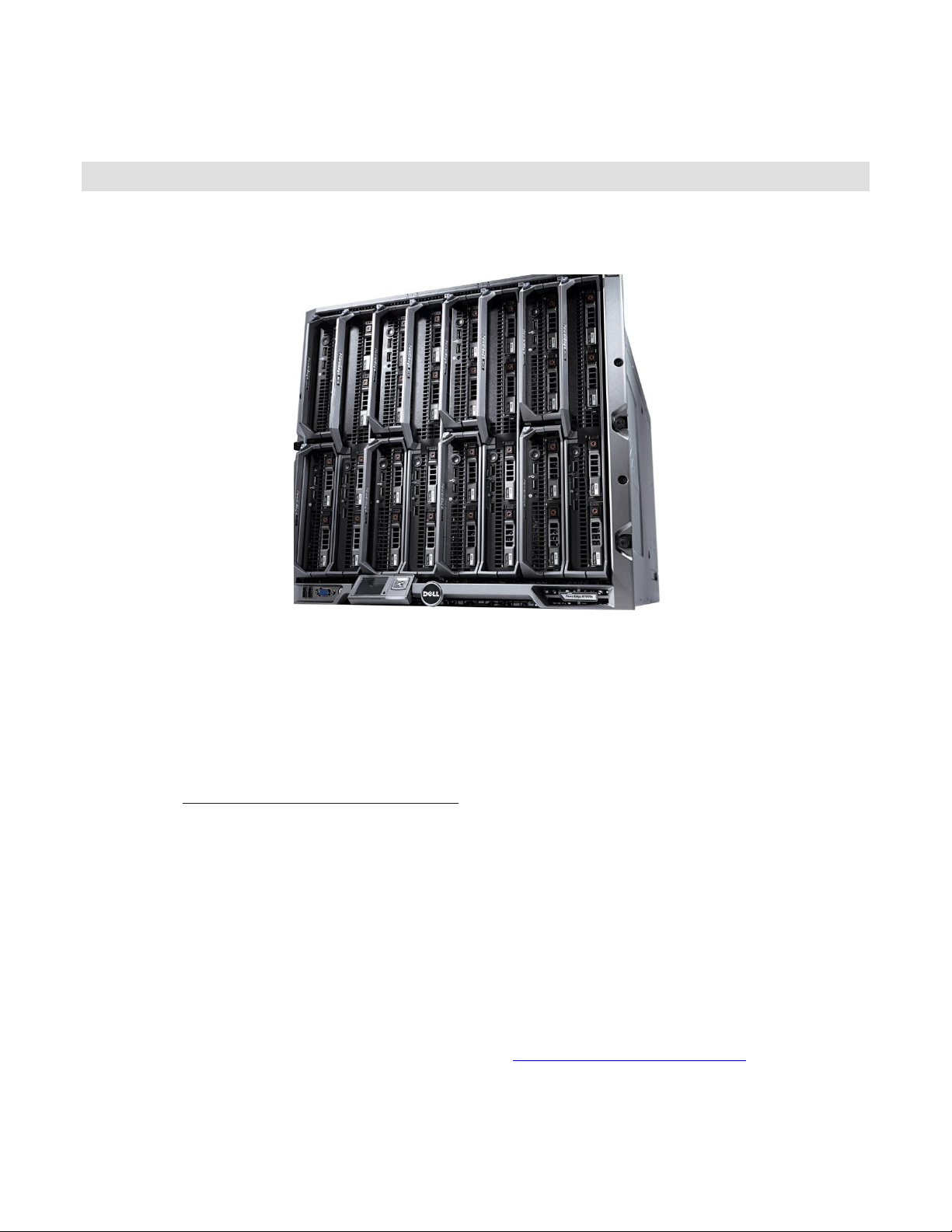
The M910 is a full height blade server that requires an M1000e chassis (shown in Figure 1) to operate.
Figure 1. M1000e
It occupies 2 slots in the M1000e rack chassis for a maximum of 8 blades in one M1000e chassis. It
can be mixed with other existing Dell blades and is designed to mix with possible future half-heightdouble-wide and full-height-double-wide blades. Some highlights are:
• Support for RAID
• Support for persistent storage (internal USB connector and two external SD card slots)
Refer to the PowerEdge M1000e Technical Guide for information on fans, power and power supply,
racks, security, and other chassis information.
4.2 Module Dimensions and Weight
Height: 38.5cm (15.2in)
Width: 5cm (2in)
Depth: 48.6cm (19.2in)
Weight: 13.1kg (29lb) maximum configuration
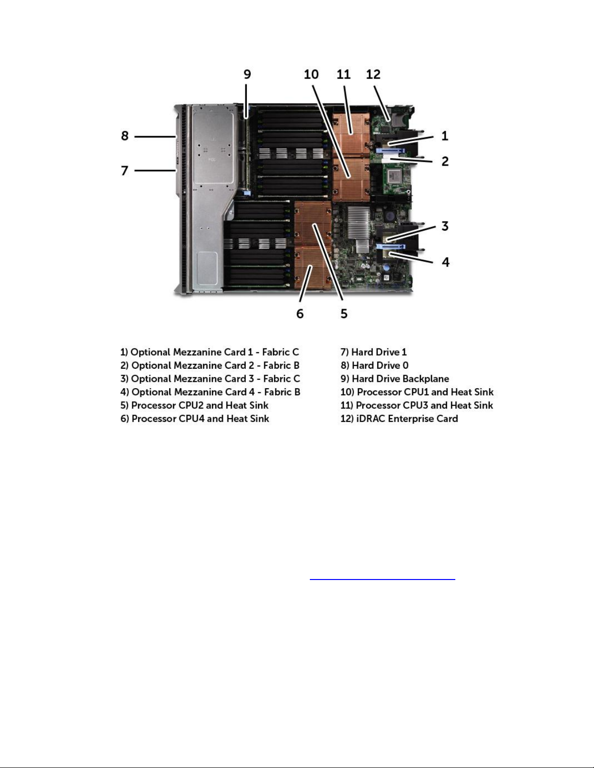
4.3 Internal Module
A view of the internal module is shown in Figure 2. See Opening and Closing the Blade in the Dell
PowerEdge Modular Systems Hardware Owner’s Manual for more information.
Dell PowerEdge M910 Technical Guide 12
Dell
Figure 2. Internal Module View
4.4 Security
Configurable client IP address range for clients connecting to iDRAC6.
4.5 Cover Latch
The blade module includes a latch for the cover. See Opening and Closing the Blade in the Dell
PowerEdge Modular Systems Hardware Owner’s Manual for more information.
4.6 TPM (Trusted Platform Module)
The TPM is used to generate/store keys, protect/authenticate passwords, and create/store digital
certificates. TPM can also be used to enable the BitLocker™ hard drive encryption feature in Windows
Server 2008. TPM is enabled through a BIOS option and uses HMAC-SHA1-160 for binding. TCM is
available in China.
Dell PowerEdge M910 Technical Guide 13
 Loading...