

Page 1

Dell™ PowerEdge™
M905, M805, M605, and M600
Getting Started
With Your System
Guide de mise en route
Primeiros passos com o sistema
Procedimientos iniciales con el sistema
Page 2

Page 3

Dell™ PowerEdge™
M905, M805, M605, and M600
Getting Started
With Your System
Page 4

Notes, Notices, and Cautions
NOTE: A NOTE indicates important information that helps you make better use
of your computer.
NOTICE: A NOTICE indicates either potential damage to hardware or loss of data
and tells you how to avoid the problem.
CAUTION: A CAUTION indicates a potential for property damage, personal injury,
or death.
____________________
Information in this document is subject to change without notice.
© 2008 Dell Inc. All rights reserved.
Reproduction in any manner whatsoever without the written permission of Dell Inc. is strictly
forbidden.
Trademarks used in this text: Dell, the DELL logo, and Dell OpenManage are trademarks of Dell Inc.;
Microsoft, Windows, and Windows Server are either trademarks or registered trademarks of Microsoft
Corporation in the United States and/or other countries; AMD and AMD Opteron are trademarks of
Advanced Micro Devices, Inc.; Intel and Xeon are registered trademarks of Intel Corporation; SUSE
is a registered trademark of Novell, Inc.; Red Hat and Enterprise Linux are registered trademarks of
Red Hat, Inc.; VMware is a registered trademarks of VMware, Inc. in the United States and/or other
jurisdictions.
Other trademarks and trade names may be used in this document to refer to either the entities claiming
the marks and names or their products. Dell Inc. disclaims any proprietary interest in trademarks and
trade names other than its own.
Model BMX01
May 2008 P/N W001C Rev. A00
Page 5

System Features
This section describes the major hardware and software features of your
system. It also provides information about other documents you may need
when setting up your system and how to obtain technical assistance.
System Enclosure Features
The M1000e system enclosure (chassis) includes the following features:
Scalability Features
• Support for up to 16 half-height or 8 full-height blades (server modules).
• Support for three layers of I/O fabric, selectable between combinations
of Ethernet, Infiniband, and Fibre Channel modules.
Up to six I/O modules may be installed in the enclosure, chosen from Fibre
Channel switches, Fibre Channel passthroughs, Infiniband switches,
Ethernet switches, and Ethernet passthrough modules.
Reliability Features
• Nine redundant, hot-pluggable system fan modules.
• Three 2360-watt, hot-pluggable power supplies and three power supply
blanks, or six 2360-watt, hot-pluggable power supplies. (Three power
supplies provide power to the system; adding three additional power
supplies provides 3+3 redundancy.)
NOTICE: Power supplies can only connect to a power distribution unit (PDU).
They cannot connect directly to an electrical outlet.
NOTICE: The system enclosure requires a 200-240V power source.
Getting Started With Your System 3
Page 6

Systems Management Features
• A Chassis Management Controller (CMC), which provides several
essential systems management features:
– Enclosure-level power management and thermal management:
• The CMC monitors system power requirements and supports the
optional Dynamic Power Supply Engagement mode so that the
CMC can enable or place power supplies in standby dynamically,
depending on load and redundancy requirements, to improve
power efficiency.
• The CMC reports real-time power consumption.
• The CMC supports an optional power ceiling, which will either
trigger an alert or actions to keep the enclosure power
consumption under the predefined ceiling.
• The CMC monitors and controls cooling fans based on actual
ambient and internal temperature measurements.
– The CMC provides comprehensive enclosure inventory and
status/error reporting.
– The CMC allows centralized configuration of the following settings:
• The CMC’s network and security settings
• Power redundancy and power ceiling settings
• I/O switches and iDRAC network settings
• First boot device on the blades
– The CMC will check I/O fabric consistency between the I/O modules
and blades and will disable system components if necessary to protect
the system hardware.
– User access security.
– An SD card slot on the CMC card supports an optional persistent
WWN/MAC feature that allows slot-based WWN/MACs for the
blades, simplifying blade installation and replacement.
4 Getting Started With Your System
Page 7

The CMC has two Ethernet ports. "Gb1" is used to connect to the external
management network. "Stack" allows CMCs in adjacent enclosures to be
daisy-chained. A 24-port Ethernet switch provides internal 100-Mb
communication with the blades, I/O modules, optional iKVM, and
optional second, redundant CMC, and provides a 10/100/1000-Mb
connection to the external management network.
NOTE: The 24-port Ethernet switch is reserved for internal communication
between the iDRAC on the blades to the CMC, then to the external
management network.
A second, optional CMC can be installed for hot-plug failover redundancy.
• An enclosure control panel that includes an LCD display which provides
current infrastructure and blade information, and error reporting.
• An optional Avocent integrated Keyboard, Video and Mouse (iKVM)
module, which includes the following features:
– The iKVM maintains all blade connections as input is switched from
each blade.
– Local iKVM access can be remotely disabled on a per blade basis via
the iDRAC user interface.
– One VGA connector.
– Two USB ports for keyboard and mouse connections.
NOTE: USB functionality is contingent on the connection of a video interface,
such as a monitor cable.
– An RJ-45 ACI port for tiering with external Dell and Avocent analog
KVM and KVM over IP switches with ARI ports. The ACI connection
takes precedence over the rear panel KVM ports.
– The iKVM can also be accessed from the control panel in the front of
the enclosure. Either front or rear KVM functionality is supported
(simultaneous functionality is not supported).
NOTE: The front iKVM is enabled by default if contention exists between the
front and rear iKVM ports. Front iKVM access can be disabled via the CMC
user interface.
Getting Started With Your System 5
Page 8

Blade Features
Performance Features
PowerEdge M905
• Four AMD™ Opteron™ 8000 Series dual-core or quad-core processors.
• A minimum of 8 GB of 677 MHz DDR2 memory modules, upgradable to
a maximum of 192 GB by installing pairs of 1-GB, 2-GB, 4-GB, or 8-GB
modules in the 24 memory module sockets on the blade system board.
The blade also supports memory sparing if eight or sixteen memory
module sockets are populated with identical memory modules.
• An SD (Secure Digital) card slot for embedded Hyperviser support.
PowerEdge M805
• Two AMD Opteron 2000 Series dual-core or quad-core processors.
• A minimum of 4 GB of 677 MHz DDR2 memory modules, upgradable to
a maximum of 128 GB by installing pairs of 1-GB, 2-GB, 4-GB, or 8-GB
modules in the 16 memory module sockets on the blade system board.
The blade also supports memory sparing if eight or sixteen memory
module sockets are populated with identical memory modules.
• An SD card slot for embedded Hyperviser support.
PowerEdge M600
• One or two Intel® Xeon® dual-core or quad-core processors
• A minimum of 1 GB of 677-MHz FBD memory modules, upgradable to
a maximum of 64 GB by installing pairs of 512-MB, 1-GB, 2-GB, 4-GB,
or 8-GB modules in the eight memory module sockets on the blade system
board. The blade also supports memory sparing or memory mirroring if all
eight memory module sockets are populated with identical memory
modules.
6 Getting Started With Your System
Page 9

PowerEdge M605
• One or two AMD Opteron 2000 Series dual-core or quad-core processors.
• A minimum of 1 GB of 677-MHz or 800-MHz DDR2 memory modules,
upgradable to a maximum of 64 GB by installing pairs of 512-MB, 1-GB,
2-GB, 4-GB, or 8-GB modules in the eight memory module sockets on
the blade system board. The blade also supports memory sparing.
Common Features
• The PowerEdge M805 and M905 blades support one or two 2.5 inch SAS
hard drives.
• The PowerEdge M600 and M605 blades support one or two 2.5-inch SATA
hard drives,
NOTE: SAS and SATA hard drives cannot be mixed within a blade.
or
one or two 2.5 inch SAS hard drives.
Hot-plug drive operation is supported if an optional RAID controller card
is installed in the blade.
• Three USB 2.0-compliant ports (PowerEdge M805 and M905) or two USB
2.0-compliant ports (PowerEdge M605 and M600) support devices such as
a mouse, keyboard, flash drive, diskette drive, or an optical drive.
NOTE: Only Dell-supplied USB devices are supported.
• An integrated VGA-compatible video subsystem with an ATI RN50 video
controller. This video subsystem contains 32 MB of SDRAM video
memory (nonupgradable). Maximum resolution is 1280 x 1024 x 65,000
colors (noninterlaced).
• An Integrated Dell Remote Access Controller (iDRAC), which provides
remote system management, blade-level power management, virtual KVM
and virtual media support, remote alerting and event logging.
• Four 1-GB Ethernet ports supported by two integrated dual-port
Broadcom 5709S controllers (PowerEdge M805 and M905), or two 1-GB
Ethernet ports supported by two integrated Broadcom 5708S controllers
(PowerEdge M600 and M605). TCP/IP Offload Engine (TOE) and iSCSI
boot are supported.
For a complete list of system features, see "Technical Specifications" on
page 15.
Getting Started With Your System 7
Page 10

The following software is included with your system:
• A System Setup program for quickly viewing and changing system
configuration information. For more information on this program, see
"Using the System Setup Program" in your
• Enhanced security features, including a system password and a setup
password, available through the System Setup program.
• System diagnostics for evaluating system components and devices.
For information about the system diagnostics, see "Running the System
Diagnostics" in your
• Video drivers for displaying many popular application programs in highresolution modes.
• Systems management software and documentation. Systems management
software is used to manage and monitor each individual blade as well as
the system as a whole, including all of the blades, network switch modules,
power supplies, and fans. Systems management software manages the
system locally and remotely on a network. Dell recommends that you use
the systems management software provided with this system.
• Optional solutions software for Web hosting, caching, or load balancing.
See your solutions software documentation for more information.
Hardware Owner’s Manual
Hardware Owner’s Manual
.
.
Supported Operating Systems
• Microsoft® Windows Server™ 2003, Web, Standard and Enterprise
(32-bit x86) Editions with SP2
• Microsoft Windows Server 2003, Standard, Enterprise, and DataCenter
(x64) Editions SP1, SP2
• Microsoft Windows Server 2003 R2 Standard and Enterprise (32- bit x86)
Editions with SP1, SP2
• Microsoft Windows Server 2003 R2 Standard, Enterprise, and DataCenter
(x64) Editions with SP1, SP2
• Microsoft Windows Server 2008, Standard Edition with SP1, SP2,
DataCenter, and EM64T
•Red Hat
• Red Hat Enterprise Linux AS and ES (version 4) (ia32
®
Enterprise Linux® AS, ES, and WS (version 4) and EM64T
)
8 Getting Started With Your System
Page 11
• Red Hat Enterprise Linux Server AS and ES (version 5) (ia32)
• Red Hat Enterprise Linux Server AS, ES, and WS (version 5) and EM64T
•SUSE
®
Linux Enterprise Server 9 (x86_64) with SP3 and EM64T
• SUSE Linux Enterprise Server 10 (x86_64) and EM64T
®
•VMWare
ESX 3.1
• VMWare ESX 3.5
Other Information You May Need
CAUTION: See the safety and regulatory information that shipped with your
system. Warranty information may be included within this document or as a
separate document.
• The
• The
• The
• The
• CDs or DVDs included with your system provide documentation and tools
• Systems management software documentation describes the features,
• Operating system documentation describes how to install (if necessary),
• Documentation for any components you purchased separately provides
Configuration Guide
provides information on configuring the system
enclosure and the blades.
Rack Installation Guide
or
Rack Installation Instructions
included
with your rack solution describes how to install your system into a rack.
Hardware Owner’s Manual
provides information about system
features and describes how to troubleshoot the system and install or
replace system components. This document may be found on the CDs
that came with your system or at
Dell Chassis Management Controller User’s Guide
support.dell.com
.
provides detailed
information on using the remote management features of the system.
for configuring and managing your system.
requirements, installation, and basic operation of the software.
configure, and use the operating system software.
information to configure and install these options.
Getting Started With Your System 9
Page 12
• Updates are sometimes included with the system to describe changes
to the system, software, and/or documentation.
NOTE: Always check for updates on support.dell.com and read the updates
first because they often supersede information in other documents.
• Release notes or readme files may be included to provide last-minute
updates to the system or documentation or advanced technical reference
material intended for experienced users or technicians.
Obtaining Technical Assistance
If you do not understand a procedure in this guide or if the system does not
perform as expected, see your Hardware Owner’s Manual.
Dell Enterprise Training and Certification is available; see dell.com/training
for more information. This service may not be offered in all locations.
Installation and Configuration
CAUTION: Before performing the following procedure, read and follow the safety
instructions and important regulatory information that shipped with your system.
For additional safety best practices information, see
www.dell.com/regulatory_compliance.
This section describes the steps required to set up your system for the first
time.
Unpack the System
Unpack your system and identify each item. Keep all shipping materials in
case you need them later.
10 Getting Started With Your System
Page 13
Install the System in a Rack
Install the system in the rack once you have read the "Safety Instructions"
located in the rack installation documentation for your system.
See your rack installation documentation for instructions on installing your
system in a rack. For power and cooling guidelines, see the rack capacity
planner tool on www.dell.com.
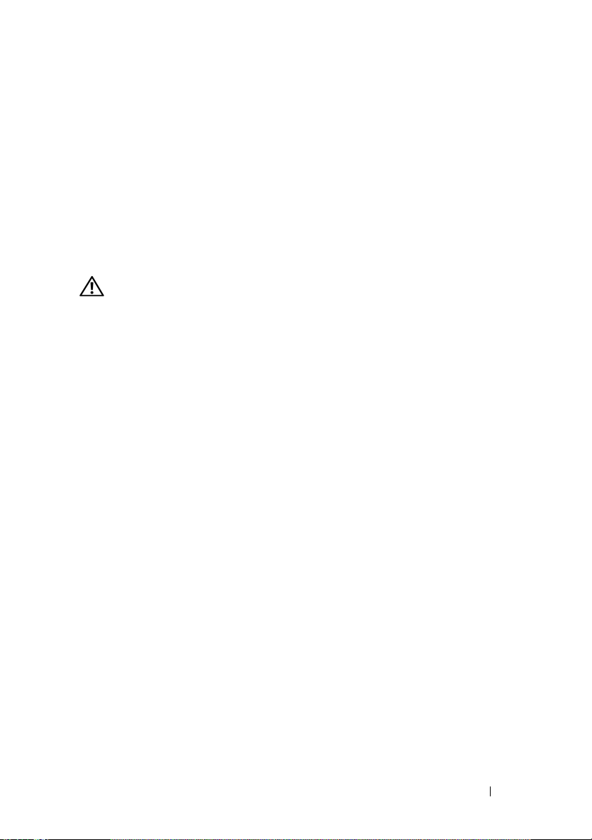
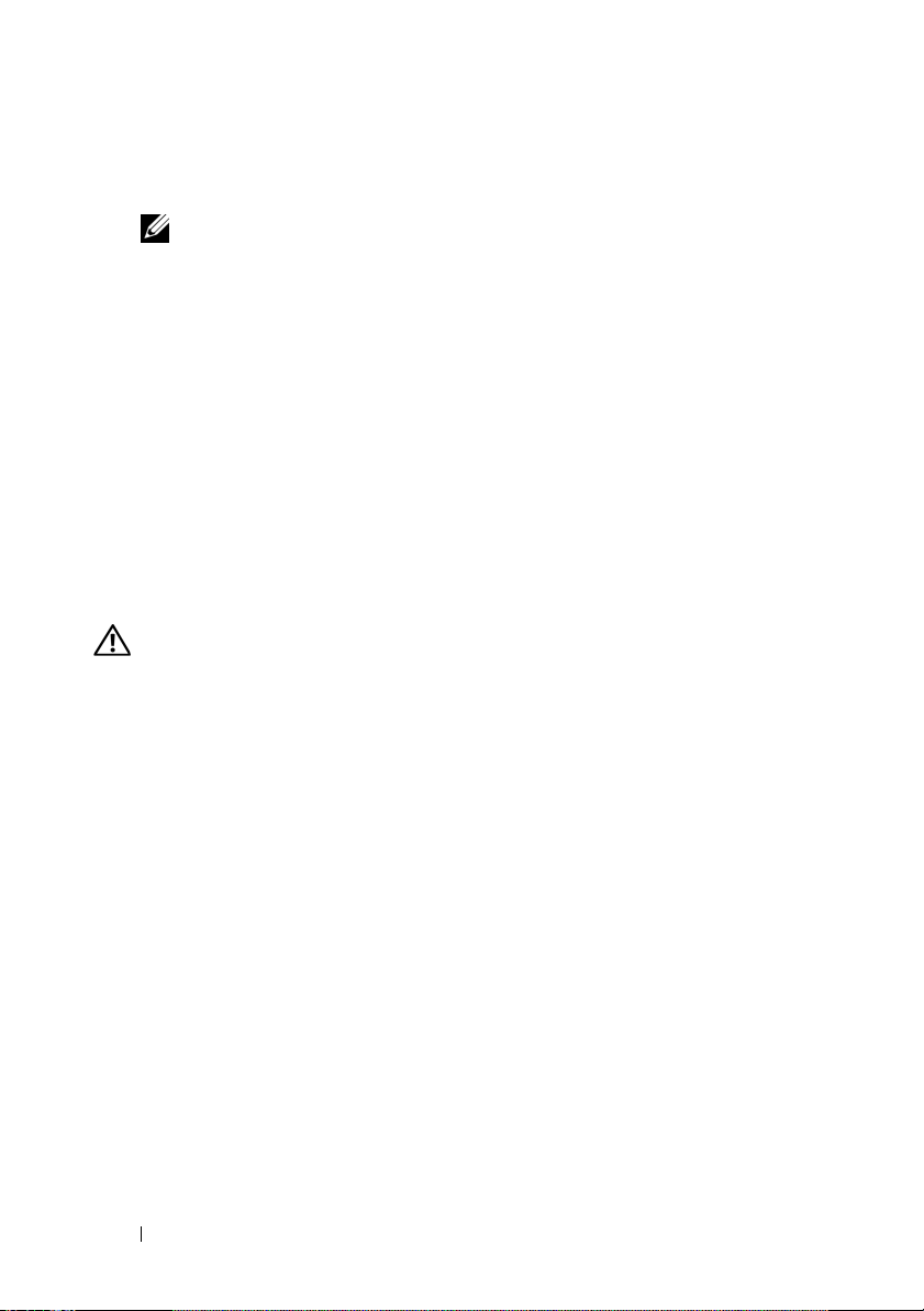
Install the Blades
Beginning at the top, slide the modules into the enclosure from left to right.
When the blade is securely installed, the handle returns to the closed
position.
Getting Started With Your System 11
Page 14
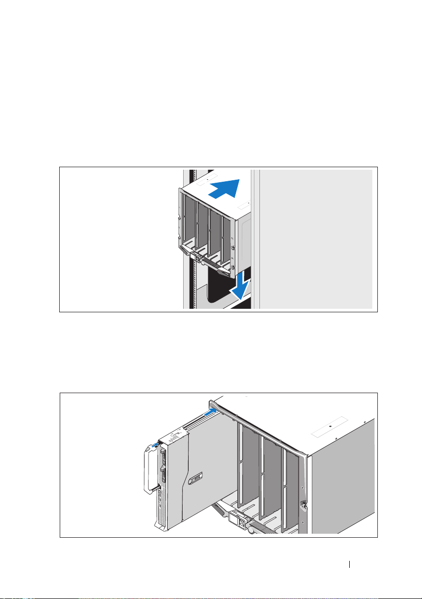
Connect the CMC and KVM Modules
Connect the serial cable and network cable from the management system to
the CMC module. If a second, optional CMC module is installed, connect it
as well. (If your chassis was shipped with M805 or M905 blades pre-installed,
the included CMC firmware will be version 1.2 or greater.)
Connect the keyboard, mouse, and monitor to the optional iKVM module.
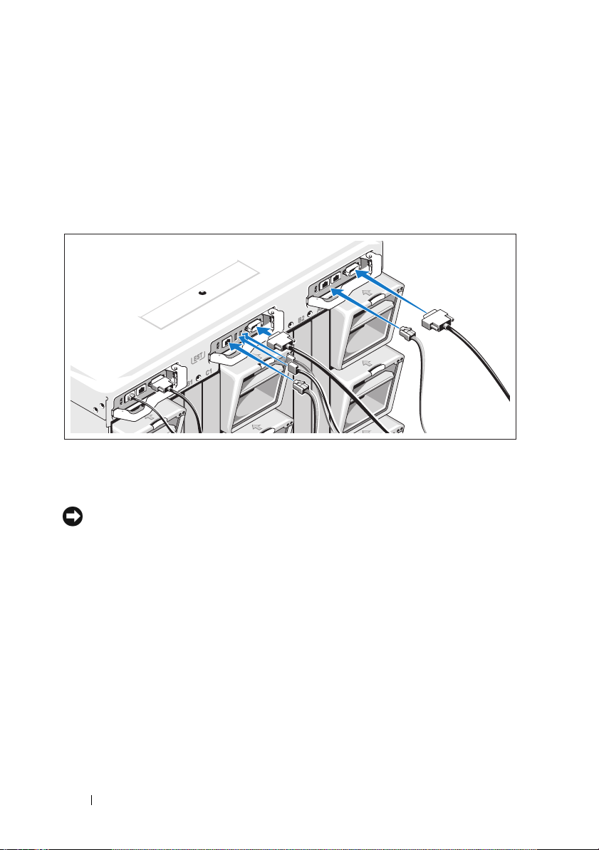
Connect the System to Power
Connect the system’s power cables to the system power supplies.
NOTICE: To prevent the power cables from being disconnected accidentally,
use the plastic clip on each power supply to secure the power cable to the power
supply, and use the Velcro strap to secure the cable to the strain-relief bar.
Next, plug the other end of the power cables into a separate power source
such as an uninterruptible power supply (UPS) or a power distribution unit
(PDU).
12 Getting Started With Your System
Page 15
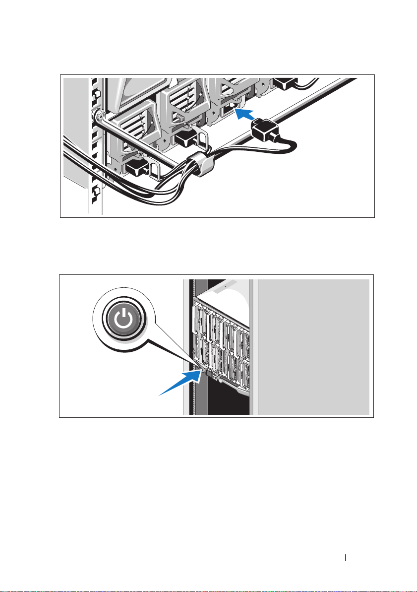
Turn on the System
Press the power button on the enclosure. The power indicator should light.
Getting Started With Your System 13
Page 16

Turn on the Blades
Press the power button on each blade, or power on the blades using
the systems management software.
Complete the 0perating System Setup
If you purchased a preinstalled operating system, see the operating system
documentation that ships with your system. To install an operating system for
the first time, see the Quick Installation Guide. Be sure the operating system
is installed before installing hardware or software not purchased with the
system.
14 Getting Started With Your System
Page 17

Technical Specifications
Blade Specifications
Processor
Processor type
PowerEdge M905
PowerEdge M805
PowerEdge M600
PowerEdge M605
Memory
Architecture
PowerEdge M600
PowerEdge M905, M805, M605
Memory module sockets
PowerEdge M905
PowerEdge M805
PowerEdge M605, M600
Memory module capacities 512 MB (PowerEdge M605 and M600),
Minimum RAM Two memory modules per processor
PowerEdge M905
PowerEdge M805
PowerEdge M600, M605
Four dual-core or quad-core AMD
Opteron 8000 Series processors
Two dual-core or quad-core AMD
Opteron 2000 Series processors
One or two dual-core or quad-core Intel
Xeon processors
One or two dual-core or quad-core AMD
Opteron 2000 Series processors
FBD memory modules, rated for
677-MHz operation
DDR2 memory modules, rated for
677-MHz operation
24 240-pin sockets
16 240-pin sockets
Eight 240-pin sockets
1 GB, 2 GB, 4 GB, or 8 GB
8 GB (Eight 1-GB memory modules)
4 GB (Four 1-GB memory modules)
1 GB (two 512-MB memory modules)
Getting Started With Your System 15
Page 18

Memory
Maximum RAM
PowerEdge M905
PowerEdge M805
PowerEdge M600, M605
Drives
Hard Drives
PowerEdge M805, M905 One or two 2.5-inch SAS hard drives
PowerEdge M600, M605
SATA configuration
SAS configuration
192 GB
128 GB
64 GB
One or two 2.5-inch SATA hard drives
One or two 2.5-inch SAS hard drives
NOTE: SAS and SATA hard drives cannot
be mixed within a M600 or M605 blade.
Connectors
External
USB
PowerEdge M805, M905
PowerEdge M600, M605
Internal
SD Card (PowerEdge M805, M905) One SD card connector
Three 4-pin, USB 2.0 compliant
Two 4-pin, USB 2.0 compliant
Ethernet Controllers
Chipset
PowerEdge M805, M905
PowerEdge M600, M605
16 Getting Started With Your System
Four Ethernet ports with TOE and iSCSI
boot support, provided by two integrated
dual-port Broadcom 5709S Ethernet
controllers
Two Ethernet ports with TOE and iSCSI
boot support, provided by two integrated
Broadcom 5708S controllers
Page 19

Video Controller
Video type ATI RN50 video controller
Video memory 32 MB
Physical
PowerEdge M905, M805
Height
Width
Depth
Weight (maximum configuration)
PowerEdge M605, M600
Height
Width
Depth
Weight (maximum configuration)
Battery
Blade battery CR 2032 3.0-V lithium ion coin cell
38.5cm (15.2 in)
5 cm (2 in)
48.6 cm (19.2 in)
11.1 kg (24.5 lb)
18.9 cm (7.4 in)
5 cm (2 in)
48.6 cm (19.2 in)
5.2-6.4 kg (11.5-14.0 lb)
System Enclosure Specifications
Physical
Height 44.0 cm (17.3 in)
Width 44.7 cm (17.6 in)
Depth 75.5 cm (29.7 in)
Weight (maximum configuration) 178.3 kg (392.2 lb)
Weight (empty) 44.6 kg (98.1 lb)
Getting Started With Your System 17
Page 20

Power Supply Module
AC/DC power supply (per power supply)
Wa t ta g e
Connector
Heat dissipation
Maximum inrush current
System Voltage Requirements
Optional Avocent iKVM Module
Rear externally accessible connectors
USB
ACI port
Video
Chassis Management Controller Module
Externally accessible connectors
Remote management
Serial
Video
Battery CR 2032 3.0-V lithium ion coin cell
SD Card One dedicated internal SD (Secure
2360 W
NEMA C20 receptacle
1205 BTU/hr. maximum
Under typical line conditions and over the
entire system ambient operating range,
the inrush current may reach 55 A per
power supply for 10 ms or less.
200 - 240V, 16A, 3-Phase, 50 /60Hz
200 - 240V, 40.5A, Single Phase, 50 /60Hz
Two 4-pin, USB 2.0-compliant connectors
for keyboard and mouse support
RJ-45
15-pin VGA
Two dedicated 10/100/1000 Mb RJ-45
ports for integrated Ethernet remote
access controller.
9-pin, DTE, 16550-compatible
15-pin VGA
Digital) flash card memory slot for
FlexAddress support.
18 Getting Started With Your System
Page 21

Enclosure Control Panel
Externally accessible connectors
USB
PowerEdge M905, M805 Three 4-pin, USB 2.0-compliant
connectors for keyboard and mouse
support
PowerEdge M605, M600
Video
Navigation Panel
Fea tu re s
Two 4-pin, USB 2.0-compliant connectors
for keyboard and mouse support
15-pin VGA
Four cursor-control keys, one select key,
LCD screen
I/O Module Specifications
PowerConnect M6220 Ethernet Switch Module
Externally accessible connectors
10/100/1000 Mbps Ethernet
Serial
Optional Modules
Four autonegotiating RJ-45 ports
One 4-pin, USB 2.0 type A connector.
(Use provided USB type A to DB9 adapter
to connect to terminal)
Two option bays. Each bay supports a
module with two 24-Gb stacking ports,
two 10-Gb CX4 copper uplinks, or two
10-Gb optical XFPs.
Cisco M7000E Infiniband Switch Module
Externally accessible connectors Eight DDR Infiniband uplink ports
Gb Ethernet Pass-Through Module
Externally accessible connectors Sixteen RJ-45
Getting Started With Your System 19
Ethernet
ports
Page 22

Fibre Channel Pass-Through Module
Externally accessible connectors
Fibre Channel transceiver
Brocade Fibre Channel Switch Module
Externally accessible connectors
Fibre Channel
Serial Port
Environmental
Sixteen external SFP ports that support
1/2/4-Gbps FC speeds
Eight physical FC ports (four enabled by
default, upgradeable to eight) supporting
1/2/4-Gbps Fibre Channel connections
RJ-45
NOTE: For additional information about environmental measurements for specific
system configurations, see dell.com/environmental_datasheets. The system is not for
use in an office environment.
Temperature
Operating
10° to 35°C (50° to 95°F)
NOTE: Decrease the maximum
temperature by 1°C (1.8°F) per 300 m (985 ft)
above 900 m (2955 ft).
Storage
Relative humidity
Operating
Storage
Maximum vibration
Operating
Storage
–40° to 65°C (–40° to 149°F)
8% to 85% (noncondensing) with a
maximum humidity gradation of 10% per
hour
5% to 95% (noncondensing)
0.26 Grms at 10–350 Hz for 15 min
1.54 Grms at 10–250 Hz for 15 min
20 Getting Started With Your System
Page 23

Environmental (continued)
Maximum shock
Operating
Storage
PowerEdge M905, M805
PowerEdge M605, M600
Altitude
Operating
Storage
One shock pulse in the positive z axis of
31 G for up to 2.6 ms
Six consecutively-executed shock pulses
in the positive and negative x, y, and z axis
of 71 G up to 2 ms
Six consecutively-executed shock pulses
in the positive and negative x, y, and z axis
of 71 G up to 2 ms
–16 to 3048 m (–50 to 10,000 ft)
–16 to 10,600 m (–50 to 35,000 ft)
Getting Started With Your System 21
Page 24

22 Getting Started With Your System
Page 25

Systèmes Dell™ PowerEdge™
M905, M805, M605 et M600
Guide de mise en route
Page 26

Remarques, avis et précautions
REMARQUE : Une REMARQUE indique des informations importantes qui peuvent
vous aider à mieux utiliser votre ordinateur.
AVIS : Un AVIS vous avertit d'un risque de dommage matériel ou de perte
de données et vous indique comment éviter le problème.
PRÉCAUTION ! Une PRÉCAUTION indique un risque potentiel d'endommagement
du matériel, de blessure corporelle ou de mort.
____________________
Les informations contenues dans ce document peuvent être modifiées sans préavis.
© 2008 Dell Inc. Tous droits réservés.
La reproduction de ce document de quelque manière que ce soit sans l'autorisation écrite de Dell Inc.
est strictement interdite.
Marques mentionnées dans ce document : Dell, le logo DELL et Dell OpenManage sont des marques
déposées de Dell Inc. ; Microsoft, Windows et Windows Server sont des marques ou des marques
déposées de Microsoft Corporation aux États-Unis et/ou dans d'autres pays ; AMD et AMD Opteron
sont des marques déposées d'Advanced Micro Devices, Inc. ; Intel et Xeon sont des marques déposées
d'Intel Corporation ; SUSE est une marque déposée de Novell, Inc. ; Red Hat et Enterprise Linux sont
des marques déposées de Red Hat, Inc. ; VMware est une marque déposée de VMware, Inc. aux ÉtatsUnis et/ou dans d'autres pays.
Tous les autres noms de marques et marques commerciales utilisés dans ce document se rapportent
aux sociétés propriétaires des marques et des noms de ces produits. Dell Inc. dénie tout intérêt
propriétaire vis-à-vis des marques et des noms de marque autres que les siens.
Modèle BMX01
Mai 2008 N/P W001C Rév. A00
Page 27

Caractéristiques du système
Cette section décrit les principales caractéristiques matérielles et logicielles
du système. Elle contient également des informations relatives à d'autres
documents pouvant être utiles à la configuration du système et indique
comment obtenir une assistance technique.
Caractéristiques du châssis
Le châssis du système M1000e présente les caractéristiques suivantes :
Evolutivité
• Prise en charge d'un maximum de 16 lames de mi-hauteur ou de 8 lames
de hauteur normale (modules du serveur).
• Prise en charge de trois couches d'E/S pouvant comprendre diverses
combinaisons de modules Ethernet, Infiniband et Fibre Channel.
Le châssis peut accueillir jusqu'à six modules d'E/S (commutateurs ou
modules d'intercommunication Fibre Channel ou Ethernet, et
commutateurs Infiniband).
Fiabilité
• Neuf modules de ventilation redondants et enfichables à chaud.
• Trois blocs d'alimentation enfichables à chaud de 2360 watts et trois
caches d'alimentation ou six blocs d'alimentation enfichables à chaud
de 2360 watts. Les trois premiers blocs alimentent le système et les trois
blocs supplémentaires sont redondants.
AVIS : Les blocs d'alimentation ne peuvent être reliés qu'à une unité de distribution
de l'alimentation (PDU). Ils ne peuvent pas être branchés directement sur une prise
secteur.
AVIS : Le châssis nécessite une source d'alimentation de 200-240 V.
Guide de mise en route 25
Page 28

Gestion des systèmes
• Contrôleur CMC (Chassis Management Controller) fournissant plusieurs
fonctions essentielles de gestion des systèmes :
– Gestion de l'alimentation et des températures au niveau du châssis :
• Le contrôleur CMC surveille les besoins en alimentation du
système et prend en charge l'utilisation du mode DPSE (Dynamic
Power Supply Engagement) fourni en option. Il peut ainsi
améliorer la gestion de l'alimentation en activant les blocs
d'alimentation ou en les mettant en veille en fonction des besoins
constatés en termes de charge de travail et de redondance.
• Le contrôleur CMC fournit des informations en temps réel sur
la consommation électrique.
• Le contrôleur CMC prend en charge la définition d'un seuil
d'alimentation (en option) qui permet de générer une alerte ou de
déclencher certaines actions visant à maintenir la consommation
en dessous d'un niveau donné.
• Le contrôleur CMC surveille le fonctionnement des ventilateurs
en se basant sur la mesure en temps réel des températures
ambiante et interne.
– Le contrôleur CMC permet de bénéficier de fonctions complètes
d'inventaire et de consignation des erreurs ou des états.
– Le contrôleur CMC permet de centraliser la configuration des
paramètres suivants :
• Paramètres réseau et de sécurité du contrôleur CMC
• Redondance de l'alimentation et définition de seuils
• Paramètres réseau des E/S pour les commutateurs et les
contrôleurs DRAC intégrés
• Définition du premier périphérique d'amorçage sur les lames
– Le contrôleur CMC vérifie la cohérence des infrastructures d'E/S
entre les modules d'E/S et les lames. Si nécessaire, il désactive
des composants afin de protéger le matériel du système.
– Sécurité des accès utilisateur.
26 Guide de mise en route
Page 29

– Un emplacement carte mémoire Secure Digital sur la carte CMC
prend en charge une fonction permanente WWN/MAC (en option)
qui permet d'utiliser des WWN/MAC à emplacement pour les lames,
ce qui simplifie leur installation et leur remplacement.
Le contrôleur CMC comprend deux ports Ethernet. Le port “Gb1” est
utilisé pour la connexion au réseau de gestion externe. Le port “Stack”
permet de relier en série les contrôleurs CMC installés dans des châssis
adjacents. Un commutateur Ethernet comprenant 24 ports gère les
communications internes (débit de 100 Mbps) avec les lames, les modules
d'E/S, le module KVM intégré en option et un second contrôleur CMC
redondant disponible en option. Il fournit également une connexion à
10/100/1000 Mbps avec le réseau de gestion externe.
REMARQUE : Le commutateur Ethernet 24 ports est réservé prioritairement
aux communications internes entre le module DRAC intégré aux lames et
le contrôleur CMC, puis au réseau de gestion externe.
Un second contrôleur CMC en option et enfichable à chaud peut être
installé pour fournir une redondance en cas de basculement.
• Le panneau de commande du châssis comprend un écran LCD qui affiche
des informations sur l'infrastructure en cours, les lames et les erreurs
rencontrées.
• Un module KVM intégré (iKVM) en option de marque Avocent offre
les fonctionnalités suivantes :
– Le module iKVM maintient actives les connexions à toutes les lames
tandis que les entrées sont envoyées uniquement à la lame choisie.
– L'accès local au module iKVM peut être désactivé à distance, lame
par lame, via l'interface utilisateur du module DRAC intégré.
– Un connecteur VGA.
– Deux ports USB pour la connexion d'un clavier et d'une souris.
REMARQUE : Les fonctionnalités USB ne peuvent être utilisées que si
une interface vidéo est connectée (câble de moniteur, par exemple).
– Un port RJ-45 ACI permet le couplage avec des commutateurs KVM
analogiques et KVM sur IP de marque Dell et Avocent dotés de ports
ARI. La connexion ACI est prioritaire sur les ports situés sur le
panneau arrière du KVM.
Guide de mise en route 27
Page 30

– Le module KVM intégré est également accessible à partir du panneau
de commande situé à l'avant du châssis. Il est possible d'utiliser le
module KVM situé à l'avant ou à l'arrière, mais pas les deux
simultanément.
REMARQUE : Le module frontal est activé par défaut en cas de conflit entre
les ports situés à l'avant et à l'arrière du module iKVM. L'accès au module
iKVM frontal peut être désactivé via l'interface utilisateur du contrôleur CMC.
Caractéristiques des lames
Performances
PowerEdge M905
• Quatre processeurs AMD™ Opteron™ 8000 Series double coeur ou
quadruple coeur.
• Un minimum de 8 Go constitué de barrettes de mémoire de 677 MHz,
extensible à 192 Go au maximum par l'installation de paires de barrettes
de 1, 2, 4 ou 8 Go dans les 24 emplacements prévus à cet effet sur la carte
système de la lame. Cette lame prend également en charge l'utilisation de
mémoire de réserve si des barrettes de mémoire identiques sont utilisées
dans huit ou seize des emplacements de module de mémoire.
• Un emplacement pour carte mémoire Secure Digital en vue de la prise
en charge de l'Hyperviser intégré.
PowerEdge M805
• Deux processeurs double coeur ou quadruple coeur AMD Opteron
2000 Series.
• Un minimum de 4 Go constitué de barrettes de mémoire DDR2 de
677 MHz, extensible à 128 Go au maximum par l'installation de paires
de barrettes de 1, 2, 4 ou 8 Go dans les 16 emplacements prévus à cet effet
sur la carte système de la lame. Cette lame prend également en charge
l'utilisation de mémoire de réserve si des barrettes de mémoire identiques
sont utilisées dans huit ou seize des sockets prévus à cet effet.
• Un emplacement pour carte mémoire Secure Digital en vue de la prise
en charge de l'Hyperviser intégré.
28 Guide de mise en route
Page 31

PowerEdge M600
• Un ou deux processeurs Intel® Xeon® double coeur ou quadruple coeur
• Un minimum de 1 Go constitué de barrettes de mémoire FBD de
677 MHz, extensible à 64 Go au maximum par l'installion de paires de
barrettes de 512 Mo ou de 1, 2, 4 ou 8 Go dans les huit sockets prévus à cet
effet sur la carte système de la lame. Si les huit emplacements mémoire
contiennent des modules identiques, il est possible d'utiliser une mémoire
de réserve ou une mise en miroir.
PowerEdge M605
• Un ou deux processeurs AMD Opteron 2000 Series double coeur ou
quadruple coeur.
• Un minimum de 1 Go constitué de barrettes de mémoire DDR2 de
677 MHz ou de 800 MHz, extensible à 64 Go au maximum par
l'installation de paires de barrettes de 512 Mo ou de 1, 2, 4 ou 8 Go dans
les huit sockets prévus à cet effet sur la carte système de la lame. Le serveur
lame prend également en charge l'utilisation d'une mémoire de réserve.
Fonctionnalités communes
• Les lames PowerEdge M805 et M905 prennent en charge un ou deux
disques durs SAS de 2,5 pouces.
• Les lames PowerEdge M600 et M605 prennent en charge un ou deux
disques durs SATA de 2,5 pouces
ou
un ou deux disques durs SAS de
2,5 pouces.
REMARQUE : Une lame ne peut pas contenir à la fois des disques durs
de type SAS et SATA.
L'ajout ou le retrait à chaud des disques est pris en charge si une carte
contrôleur RAID en option est installée dans la lame.
• Trois ports compatibles USB 2.0 (PowerEdge M805 et M905) ou deux
ports compatibles USB 2.0 (PowerEdge M605 et M600) assurent la prise
en charge des périphériques suivants : souris, clavier, lecteur flash, lecteur
de disquette et lecteur optique.
REMARQUE : Seuls les périphériques USB fournis par Dell sont pris
en charge.
Guide de mise en route 29
Page 32

• Sous-système vidéo intégré compatible VGA comprenant un contrôleur
vidéo ATI RN50. Ce sous-système vidéo contient 32 Mo de mémoire
vidéo SDRAM (non extensible). La résolution maximale est de
1280x1024x 65000 couleurs (non-entrelacé).
• Contrôleur DRAC intégré (iDRAC, Integrated Dell Remote Access
Controller) fournissant différentes capacités : gestion de systèmes à
distance, gestion de l'alimentation au niveau des lames, prise en charge
des modules KVM et des médias virtuels, déclenchement d'alertes et
consignation d'événements à distance.
• Quatre ports Ethernet de 1 Go pris en charge par deux contrôleurs
Broadcom 5709S intégrés à double port (PowerEdge M805 et M905),
ou deux ports Ethernet de 1 Go pris en charge par deux contrôleurs
Broadcom 5708S intégrés (PowerEdge M600 et M605). Le protocole TOE
(TCP/IP Offload Engine) et l'amorçage iSCSI sont pris en charge.
Pour une liste complète des caractéristiques du système, reportez-vous au
“Spécifications techniques”, page 38.
Les logiciels suivants sont livrés avec le système :
• Programme de configuration du système permettant de consulter et
de modifier rapidement les informations sur la configuration du système.
Pour plus d'informations sur ce programme, voir “Using the System Setup
Program” (Utilisation du programme de configuration du système), dans
le document
Hardware Owner's Manual
(Manuel du propriétaire).
• Fonctions de sécurité avancées (disponibles dans le programme de
configuration du système) permettant de définir un mot de passe système
et un mot de passe de configuration.
• Diagnostics permettant de tester les composants et les périphériques
du système. Pour plus d'informations sur les diagnostics du système,
voir “Running the System Diagnostics” (Exécution des diagnostics
du système), dans le document
Hardware Owner's Manual
(Manuel
du propriétaire).
• Pilotes vidéo permettant d'afficher un grand nombre d'applications très
répandues dans les modes à haute résolution.
30 Guide de mise en route
Page 33

• Logiciel de gestion des systèmes et documentation associée. Les logiciels
de gestion des systèmes permettent de gérer et de surveiller chaque lame
de façon individuelle, mais aussi le système dans son ensemble, en
incluant les lames, les modules de commutation réseau, les blocs d'alimentation et les ventilateurs. Ces logiciels peuvent être utilisés pour gérer le
système localement ou à distance via le réseau. Dell recommande l'utilisation du logiciel de gestion des systèmes fourni avec le système.
• Solutions en option pour l'hébergement Web, la mise en cache ou
l'équilibrage de charge. Pour plus d'informations, consultez la
documentation accompagnant les logiciels.
Systèmes d'exploitation pris en charge
• Microsoft® Windows Server™ 2003 éditions Web, Standard et Enterprise
(32 bits, x86) avec SP2
• Microsoft Windows Server 2003, éditions Standard, Enterprise et
Datacenter (x64) avec SP1 ou SP2
• Microsoft Windows Server 2003 R2 éditions Standard et Enterprise
(32 bits, x86) avec SP1 ou SP2
• Microsoft Windows Server 2003 R2, éditions Standard, Enterprise et
Datacenter (x64) avec SP1 ou SP2
• Microsoft Windows Server 2008, éditions Standard avec SP1 ou SP2,
DataCenter et EM64T
•Red Hat
• Red Hat Enterprise Linux AS et ES (version 4) (ia32
• Red Hat Enterprise Linux Server AS et ES (version 5) (ia32)
• Red Hat Enterprise Linux Server AS, ES et WS (version 5) et EM64T
•SUSE
• SUSE Linux Enterprise Server 10 (x86_64) et EM64T
•VMWare
• VMWare ESX 3.5
®
Enterprise Linux® AS, ES et WS (version 4) et EM64T
)
®
Linux Enterprise Server 9 (x86_64) avec SP3 et EM64T
®
ESX 3.1
Guide de mise en route 31
Page 34

Autres informations utiles
PRÉCAUTION ! Consultez les informations de sécurité et de garantie fournies
avec votre système. Les informations sur la garantie se trouvent soit dans ce
document, soit à part.
•Le
Configuration Guide
sur la configuration du châssis du système et des lames.
• Les documents
Rack Installation Instructions
avec la solution rack décrivent l'installation du système.
• Le document
contient des informations sur les caractéristiques du système, ainsi que des
instructions relatives au dépannage et à l'installation ou au remplacement
de composants. Il se trouve sur les CD fournis avec le système et sur le site
support.dell.com
• Le document
(Contrôleur de gestion de châssis Dell) contient des informations
détaillées sur l'utilisation des fonctions de gestion à distance du système.
• Les CD ou les DVD fournis avec le système contiennent des documents et
des outils relatifs à la configuration et à la gestion du système.
• La documentation relative aux logiciels de gestion du système contient
des informations sur les fonctionnalités, l'installation et l'utilisation
de base de ces logiciels, ainsi que sur la configuration requise.
• La documentation du système d'exploitation indique comment installer
(au besoin), configurer et utiliser le système d'exploitation.
• La documentation fournie avec les composants achetés séparément
indique comment installer et configurer ces options.
• Des mises à jour sont parfois fournies avec le système. Elles décrivent les
modifications apportées au système, aux logiciels ou à la documentation.
Rack Installation Guide
Hardware Owner's Manual
Dell Chassis Management Controller User’s Guide
(Guide de configuration) fournit des informations
(Guide d'installation du rack) et
(Instructions d'installation du rack) fournis
(Manuel du propriétaire)
.
REMARQUE : Vérifiez toujours si des mises à jour sont disponibles sur le site
support.dell.com et lisez-les en premier, car elles remplacent souvent
les informations contenues dans les autres documents.
• Si des notes d'édition ou des fichiers lisez-moi (readme) sont fournis,
ils contiennent des mises à jour de dernière minute apportées au système
ou à la documentation, ou bien des informations techniques destinées aux
utilisateurs expérimentés ou aux techniciens.
32 Guide de mise en route
Page 35

Obtention d'une assistance technique
Si vous ne comprenez pas une procédure décrite dans ce guide ou si le
système ne réagit pas comme prévu, reportez-vous au document Hardware
Owner's Manual (Manuel du propriétaire).
Des formations et certifications Dell Enterprise sont disponibles. Pour plus
d'informations, consultez le site dell.com/training. Ce service n'est disponible
que dans certains pays.
Installation et configuration
PRÉCAUTION ! Avant de commencer la procédure suivante, lisez et respectez
les consignes de sécurité et les informations importantes sur les réglementations
fournies avec le système. Pour plus d'informations sur les meilleures pratiques en
matière de sécurité, voir le site www.dell.com/regulatory_compliance.
Cette section décrit les étapes devant être exécutées lors de la configuration
initiale du système.
Déballage du système
Sortez le système de son emballage et identifiez chaque élément. Conservez
les matériaux d'emballage au cas où vous en auriez besoin ultérieurement.
Installation du système dans un rack
Commencez par lire les consignes de sécurité qui se trouvent dans la
documentation d'installation du rack, puis installez le système dans le rack.
Consultez la documentation d'installation du rack pour obtenir les instructions appropriées. Pour obtenir des directives concernant l'alimentation et
le refroidissement, reportez-vous à l'outil de planification de capacité des
racks disponible sur le site www.dell.com.
Guide de mise en route 33
Page 36

Installation des lames
Insérez les modules dans le châssis en commençant par le haut et en
procédant de gauche à droite. Lorsqu'une lame est correctement installée,
la poignée revient en position fermée.
34 Guide de mise en route
Page 37

Connexion du contrôleur CMC et des modules KVM
Connectez les câbles série et réseau du système de gestion au module CMC.
Si un second module CMC en option est installé, connectez-le également.
Si votre châssis a été fourni avec des lames M805 ou M905 préinstallées,
le micrologiciel CMC inclus est de version 1.2 ou ultérieure.
Connectez le clavier, la souris et le moniteur au module iKVM en option.
Branchement du système sur le secteur
Enfichez les câbles d'alimentation du système dans les blocs d'alimentation.
AVIS : Pour éviter que les câbles d'alimentation ne soient débranchés
accidentellement, utilisez le clip en plastique situé sur chaque bloc d'alimentation
pour fixer le câble. Utilisez également la bande Velcro pour maintenir le câble sur
la barre de retenue.
Branchez ensuite l'autre extrémité des cordons d'alimentation sur une source
d'alimentation autonome, comme un onduleur ou une unité de distribution
de l'alimentation.
Guide de mise en route 35
Page 38

Mise sous tension du système
Appuyez sur le bouton d'alimentation du châssis. Le voyant d'alimentation
doit s'allumer.
36 Guide de mise en route
Page 39

Mise sous tension des lames
Mettez chaque lame sous tension en appuyant sur son bouton d'alimentation
ou en utilisant le logiciel de gestion des systèmes.
Finalisation de l'installation du système d'exploitation
Si vous avez acheté un système d'exploitation préinstallé, consultez tout
d'abord la documentation associée, qui a été fournie avec l'ordinateur. Si vous
installez un système d'exploitation pour la première fois, consultez le
document Quick Installation Guide (Guide d'installation rapide). Veillez à
installer le système d'exploitation avant tout élément matériel ou logiciel
acheté séparément.
Guide de mise en route 37
Page 40

Spécifications techniques
Spécifications des lames
Processeur
Type de processeur
PowerEdge M905
PowerEdge M805
PowerEdge M600
PowerEdge M605
Mémoire
Architecture
PowerEdge M600
PowerEdge M905, M805, M605
Connecteurs mémoire
PowerEdge M905
PowerEdge M805
PowerEdge M605, M600
Capacité des barrettes de mémoire 512 Mo (PowerEdge M605 et M600),
RAM minimale Deux barrettes de mémoire par
PowerEdge M905
PowerEdge M805
PowerEdge M600, M605
Quatre processeurs AMD Opteron 8000
Series double coeur ou quadruple coeur
Deux processeurs AMD Opteron 2000
Series double coeur ou quadruple coeur
Un ou deux processeurs Intel Xeon
double coeur ou quadruple coeur.
Un ou deux processeurs AMD
Opteron 2000 Series double coeur
ou quadruple coeur
Barrettes de mémoire FBD, cadencées
à677MHz
Barrettes de mémoire DDR2, cadencées
à677MHz
24 sockets à 240 broches
16 sockets à 240 broches
Huit sockets à 240 broches
1Go, 2Go, 4Go ou 8Go
processeur
8 Go (huit barrettes de mémoire de 1 Go)
4 Go (quatre barrettes de mémoire
de 1 Go)
1 Go (deux barrettes de 512 Mo)
38 Guide de mise en route
Page 41

Mémoire (suite)
RAM maximale
PowerEdge M905
PowerEdge M805
PowerEdge M600, M605
Lecteurs
Disques durs
PowerEdge M805, M905 Un ou deux disques durs SAS enfichables
PowerEdge M600, M605
Configuration SATA
Configuration SAS
192 Go
128 Go
64 Go
à chaud de 2,5 pouces
Un ou deux disques durs SATA de
2,5 pouces
Un ou deux disques durs SAS
de 2,5 pouces
REMARQUE : Une lame M600 ou M605 ne
peut pas contenir à la fois des disques durs
de type SAS et SATA.
Connecteurs
Externes
USB
PowerEdge M805, M905
PowerEdge M600, M605
Interne
Carte mémoire Secure Digital
(PowerEdge M805, M905)
Trois connecteurs à 4 broches,
compatibles USB 2.0
Deux connecteurs à 4 broches,
compatibles USB 2.0
Un connecteur pour carte mémoire
Secure Digital
Guide de mise en route 39
Page 42

Contrôleurs Ethernet
Circuit microprogrammé
PowerEdge M805, M905
PowerEdge M600, M605
Contrôleur vidéo
Type de vidéo Contrôleur vidéo ATI RN50
Mémoire vidéo 32 Mo
Caractéristiques physiques
PowerEdge M905, M805
Hauteur
Largeur
Profondeur
Poids (configuration maximale)
PowerEdge M605, M600
Hauteur
Largeur
Profondeur
Poids (configuration maximale)
Quatre ports Ethernet avec prise en
charge TOE et amorçage iSCSI, assurée
par deux contrôleurs Ethernet Broadcom
5709S à double port
Deux ports Ethernet avec prise en charge
TOE et amorçage iSCSI, assurée par deux
contrôleurs Broadcom 5708S intégrés
38,5 cm (15,2 pouce)
5 cm (2 pouces)
48,6 cm (19,2 pouces)
11,1 kg (24,5 livres)
18,9 cm (7,4 pouces)
5 cm (2 pouces)
48,6 cm (19,2 pouces)
5,2 à 6,4 kg (11,5 à 14 livres)
Batterie
Pile pour serveur lame Pile bouton au lithium-ion CR2032 (3 V)
40 Guide de mise en route
Page 43

Spécifications du châssis
Caractéristiques physiques
Hauteur 44,0 cm (17,3 pouces)
Largeur 44,7 cm (17,6 pouces)
Profondeur 75,5 cm (29,7 pouces)
Poids (configuration maximale) 178,3 kg (392,2 livres)
Poids (à vide) 44,6 kg (98,1 livres)
Bloc d'alimentation
Bloc d'alimentation en CA/CC (selon la tension en vigueur)
Puissance
Connecteur
Dissipation thermique
Appel de courant maximal
Tension requise pour le système
2360 W
Connecteur C20 NEMA
1205 BTU/h. maximum
Dans des conditions de ligne typiques
et dans toute la gamme ambiante de
fonctionnement du système, l'appel
de courant peut atteindre 55 A par bloc
d'alimentation pendant un maximum
de 10 ms.
200 - 240 V, 16A, triphasé, 50/60Hz
200 - 240 V, 40,5A, monophasé, 50/60Hz
Module Avocent iKVM en option
Connecteurs arrière accessibles de l'extérieur
USB
Port ACI
Vidéo
Deux connecteurs USB 2.0 à 4 broches
pour le branchement d'un clavier et
d'une souris
RJ-45
VGA, 15 broches
Guide de mise en route 41
Page 44

Module contrôleur de gestion du châssis (CMC)
Connecteurs accessibles de l'extérieur
Gestion à distance
Série
Vidéo
Batterie Pile bouton au lithium-ion CR2032 (3 V)
Carte Secure Digital Un emplacement pour carte Secure
Panneau de commande du châssis
Connecteurs accessibles de l'extérieur
USB
PowerEdge M905, M805 Trois connecteurs USB 2.0 à 4 broches
PowerEdge M605, M600
Vidéo
Panneau de navigation
Fonctionnalités
Deux connecteurs RJ-45
10/100/1000 Mbps dédiés pour le
contrôleur d'accès à distance Ethernet
intégré.
Connecteur DTE à 9 broches,
compatible 16550
VGA, 15 broches
Digital dédié à la prise en charge de
FlexAddress.
pour le branchement d'un clavier et
d'une souris
Deux connecteurs USB 2.0 à 4 broches
pour le branchement d'un clavier et d'une
souris
VGA, 15 broches
Quatre touches de commande du curseur,
une touche de sélection, un écran LCD
42 Guide de mise en route
Page 45

Spécifications des modules d'E/S
Module commutateur Ethernet PowerConnect M6220
Connecteurs accessibles de l'extérieur
Ethernet - 10/100/1000 Mbps
Série
Modules en option
Module commutateur Cisco M7000E Infiniband
Connecteurs accessibles de l'extérieur Huit liaisons montantes DDR Infiniband
Module d'intercommunication Ethernet Gigabit
Connecteurs accessibles de l'extérieur Seize ports
Quatre ports RJ-45 à négociation
automatique
Un connecteur USB 2.0 de type A à
quatre broches. Pour la connexion à la
console, utilisez l'adaptateur USB fourni
(type A vers DB9).
Deux baies d'option. Chaque baie prend
en charge un module équipé de deux
ports d'empilage de 24 Go, de deux
liaisons montantes CX4 de 10 Go ou
de deux ports XFP de 10 Go sur fibre
optique.
Ethernet
RJ-45
Module d'intercommunication Fibre Channel
Connecteurs accessibles de l'extérieur
Émetteur-récepteur Fibre Channel
Module commutateur Fibre Channel Brocade
Connecteurs accessibles de l'extérieur
Connexions Fibre Channel
Port série
Seize ports SFP externes qui prennent en
charge des vitesses FC de 1/2/4 Gbps
Huit ports physiques Fibre Channel dont
quatre sont activés par défaut, prenant en
charge les connexions Fibre Channel à
1/2/4 Gbps
RJ-45
Guide de mise en route 43
Page 46

Environnement
REMARQUE : Pour plus d'informations concernant les mesures d'exploitation liées à
différentes configurations spécifiques, rendez-vous à l'adresse
dell.com/environmental_datasheets. Le système n'est pas conçu pour être utilisé dans
un bureau.
Température
Fonctionnement
De 10° à 35°C (50 à 95°F)
REMARQUE : Au-dessus de 900 m
(2955 pieds), la température maximale doit
être diminuée de 1°C (1,8°F) tous les 300 m
(985 pieds).
Stockage
Humidité relative
Fonctionnement
Stockage
Tolérance maximale aux vibrations
Fonctionnement
Stockage
Choc maximal
Fonctionnement
Stockage
PowerEdge M905, M805
PowerEdge M605, M600
Altitude
Fonctionnement
Stockage
De -40° à 65°C (-40° à 149°F)
De 8% à 85% (sans condensation) avec
une gradation d'humidité maximale
de 10% par heure.
De 5% à 95% (sans condensation)
0,26 Grms avec un balayage de 10
à 350 Hz pendant 15 min
1,54 Grms avec un balayage de 10
à 250 Hz pendant 15 minutes
Une impulsion de choc de 31 G pendant
un maximum de 2,6 ms sur l'axe z positif
Six chocs consécutifs de 71 G pendant un
maximum de 2 ms en positif et négatif
sur les axes x, y et z
Six chocs consécutifs de 71 G pendant un
maximum de 2 ms en positif et négatif
sur les axes x, y et z
De -16 à 3 048 m (-50 à 10 000 pieds)
De -16 à 10 600 m (-50 à 35 000 pieds)
44 Guide de mise en route
Page 47

Dell™ PowerEdge™
M905, M805, M605 e M600
Primeiros passos
com o sistema
Page 48

Notas, avisos e advertências
NOTA: As NOTAS fornecem informações importantes que o ajudam a utilizar
melhor o computador.
AVISO: As mensagens de AVISO informam sobre possíveis danos ao hardware
ou perda de dados e indicam como evitar o problema.
ADVERTÊNCIA: As mensagens de ADVERTÊNCIA indicam possíveis danos
de propriedade, ferimentos pessoais ou morte.
____________________
As informações contidas neste documento estão sujeitas a alterações sem aviso prévio.
© 2008 Dell Inc. Todos os direitos reservados.
Fica proibida a reprodução por quaisquer meios sem a permissão por escrito da Dell Inc.
Marcas comerciais utilizadas neste texto: Dell, o logotipo DELL e Dell OpenManage são marcas
comerciais da Dell Inc.; Microsoft, Windows e Windows Server são marcas comerciais ou registradas
da Microsoft Corporation nos Estados Unidos e/ou em outros países; AMD e AMD Opteron são marcas
comerciais da Advanced Micro Devices, Inc.; Intel e Xeon são marcas registradas da Intel Corporation;
SUSE é uma marca registrada da Novell, Inc.; Red Hat e Enterprise Linux são marcas registradas da
Red Hat, Inc.; VMware é uma marca registrada da VMware, Inc. nos Estados Unidos e/ outras
jurisdições.
Outras marcas e nomes comerciais podem ser mencionados neste documento em referência às
entidades proprietárias das marcas e nomes ou seus produtos. A Dell Inc. renuncia ao direito
de qualquer participação em nomes e marcas comerciais que não sejam de sua propriedade.
Modelo BMX01
Maio de 2008 N/P W001C Rev. A00
Page 49

Recursos do sistema
Esta seção descreve os principais recursos de hardware e software do sistema.
Também fornece informações sobre outros documentos que podem ser úteis
durante a configuração do sistema e quando precisar de assistência técnica.
Recursos da caixa do sistema
A caixa do sistema (chassi) M1000e inclui os seguintes recursos:
Recursos de escalabilidade
• Suporte para até 16 blades de meia altura e 8 de altura total (módulos
de servidor).
• Suporte para três camadas de estrutura de E/S que podem ser selecionadas
entre combinações de módulos Ethernet, Infiniband e de canais de fibra
óptica.
Até seis módulos de E/S podem ser instalados na caixa, escolhidos entre
comutadores de canais de fibra óptica, passagens de fibra óptica,
comutadores Infiniband, comutadores Ethernet e módulos de passagem
Ethernet.
Recursos de confiabilidade
• Nove módulos redundantes de ventiladores de sistema com conexão
automática.
• Três fontes de alimentação de 2360 W com conexão automática e três
módulos vazios para fontes de alimentação ou seis fontes de alimentação
de 2360 W com conexão automática. Três fontes de alimentação fornecem
energia ao sistema, enquanto as três fontes adicionais proporcionam
redundância de 3+3.
AVISO: As fontes de alimentação só podem ser conectadas a uma PDU (unidade
de distribuição de energia). Não é possível conectá-las diretamente a uma tomada
elétrica.
AVISO: A caixa do sistema requer uma fonte de energia de 200 V a 240 V.
Primeiros passos com o sistema 47
Page 50

Recursos de gerenciamento do sistema
• Um controlador de gerenciamento do chassi (CMC) que fornece vários
recursos essenciais para o gerenciamento do sistema:
– Gerenciamento de energia e gerenciamento térmico da caixa:
• O CMC monitora os requisitos de energia do sistema e oferece
suporte ao modo opcional de ajuste de fonte de energia dinâmica
para poder ativar as fontes de alimentação ou colocá-las no modo
de espera dinamicamente para otimizar a energia, dependendo
dos requisitos de carga e redundância.
• O CMC informa o consumo de energia em tempo real.
• O CMC oferece suporte para um teto de energia opcional que
acionará um alerta ou ações para manter o consumo de energia
da caixa sob o teto pré-definido.
• O CMC monitora e controla os ventiladores de resfriamento com
base nas medidas reais de temperatura ambiente e interna.
– O CMC fornece um inventário abrangente da caixa e indicações
de estado e erros.
– O CMC permite a configuração centralizada dos seguintes ajustes:
• As configurações de segurança e de rede do CMC
• Configurações de redundância e teto de energia
• Configurações de comutadores de E/S e rede iDRAC
• Primeiro, inicialize o dispositivo das lâminas
– O CMC verificará a consistência da estrutura de E/S entre os módulos
e lâminas de E/S e desativará os componentes do sistema, se
necessário, para proteger o hardware do sistema.
– Segurança de acesso do usuário.
– Um slot de cartão SD no cartão CMC oferece suporte a um recurso
WWN/MAC persistente opcional que permite WWN/MACs
baseados em slot para as lâminas, simplificando a instalação e a
substituição de lâmina.
48 Primeiros passos com o sistema
Page 51

O CMC possui duas portas Ethernet. A porta "Gb1" é usada para conectar
à rede externa de gerenciamento. A "pilha" permite que os CMCs em
caixas adjacentes sejam conectados em margarida. Um comutador
Ethernet de 24 portas fornece comunicação interna de 100 Mb com as
lâminas, módulos de E/S, iKVM opcional e um segundo CMC opcional e
redundante, além de fornecer uma conexão de 10/100/1000 Mb à rede
externa de gerenciamento.
NOTA: O comutador Ethernet de 24 portas é reservado para comunicação
interna da iDRAC das lâminas com o CMC e com a rede externa de
gerenciamento.
Um segundo CMC opcional pode ser instalado para obter uma conexão
automática redundante.
• Um painel de controle da caixa contendo um monitor LCD que fornece
informações atuais sobre a infra-estrutura e a lâmina, além de relatórios
de erros.
• Um módulo Avocent opcional integrado para teclado, vídeo e mouse
(iKVM) que inclui os seguintes recursos:
– O iKVM mantém todas as conexões das lâminas ao alternar a entrada
de cada lâmina.
– Acesso local ao iKVM que pode ser desativado de forma remota para
cada lâmina através da interface iDRAC.
– Um conector VGA.
– Duas portas USB para conexões de teclado e mouse.
NOTA: A funcionalidade das portas USB depende da conexão de uma
interface de vídeo, como um cabo de monitor.
– Uma porta ACI RJ-45 para ser empilhada com KVMs analógicos Dell
e Avocent e com os comutadores KVM sobre IP com portas ARI.
A conexão ACI tem prioridade sobre as portas KVM do painel traseiro.
– O iKVM também pode ser acessado do painel de controle da parte
frontal da caixa. Há suporte tanto para os recursos do KVM frontal
quanto do traseiro, mas não para o funcionamento simultâneo.
NOTA: O iKVM frontal é ativado por padrão se houver contenção entre as
portas iKVM frontal e traseira. O acesso ao iKVM frontal pode ser desativado
pela interface do CMC.
Primeiros passos com o sistema 49
Page 52

Recursos da lâmina
Recursos de desempenho
PowerEdge M905
• Quatro processadores de dois ou quatro núcleos AMD™ Opteron™
série 8000.
• Mínimo de 8 GB em módulos de memória DDR2 de 677 MHz, que podem
ser atualizados para no máximo 192 GB com a instalação de pares de
módulos de 1 GB, 2 GB, 4 GB ou 8 GB nos 24 soquetes dos módulos
de memória da placa de sistema das lâminas. A lâmina também admite
sobressalência de memória, caso todos os oito ou dezesseis soquetes para
módulos de memória estejam ocupados com módulos idênticos.
• Veja o slot da placa SD (Secure Digital) para obter suporte Hyperviser
incorporado.
PowerEdge M805
• Dois processadores de dois ou quatro núcleos AMD Opteron série 2000.
• Mínimo de 4 GB em módulos de memória DDR2 de 677 MHz, que podem
ser atualizados para no máximo 128 GB com a instalação de pares de
módulos de 1 GB, 2 GB, 4 GB ou 8 GB nos 16 soquetes dos módulos
de memória da placa de sistema das lâminas. A lâmina também admite
sobressalência de memória, caso todos os oito ou dezesseis soquetes para
módulos de memória estejam ocupados com módulos idênticos.
• Veja o slot da placa SD para obter suporte Hyperviser incorporado.
PowerEdge M600
• Um ou dois processadores de dois ou quatro núcleos Intel® Xeon®.
• Mínimo de 1 GB em módulos de memória FBD de 677 MHz, que podem
ser atualizados para no máximo 64 GB com a instalação de pares de
módulos de 512 MB, 1 GB, 2 GB ou 4 GB nos oito soquetes dos módulos
de memória da placa de sistema das lâminas. A lâmina também admite
sobressalência ou espelhamento de memória, caso todos os oito soquetes
para módulos de memória estejam ocupados com módulos idênticos.
50 Primeiros passos com o sistema
Page 53

PowerEdge M605
• Um ou dois processadores de dois ou quatro núcleos AMD Opteron
série 2000.
• Mínimo de 1 GB em módulos de memória DDR2 de 677 MHz ou
800 MHz, que podem ser atualizados para no máximo 64 GB com a
instalação de pares de módulos de 512 MB, 1 GB, 2 GB, 4 GB ou 8 GB nos
oito soquetes dos módulos de memória da placa de sistema das lâminas.
A lâmina também oferece suporte para sobressalência de memória.
Recursos comuns
• As lâminas PowerEdge M805 e M905 oferecem suporte a uma ou duas
unidades de disco rígido SAS de 2,5 polegadas.
• As lâminas PowerEdge M600 e M605 oferecem suporte a uma ou duas
unidades de disco rígido SATA de 2,5 polegadas
ou
uma ou duas unidades
de disco rígido SAS de 2,5 polegadas.
NOTA: As unidades de disco rígido SAS e SATA não podem ser misturadas
na mesma lâmina.
A operação da unidade de conexão automática é admitida se houver uma
placa controladora RAID opcional instalada na lâmina.
• Três portas compatíveis com USB 2.0 (PowerEdge M805 e M905) ou duas
portas compatíveis com USB 2.0 (PowerEdge M605 e M600) oferecem
suporte a dispositivos como mouse, teclado, unidade flash ou unidade
óptica.
NOTA: Somente os dispositivos USB fornecidos pela Dell possuem suporte.
• Um subsistema de vídeo compatível com o padrão VGA, com um
controlador de vídeo ATI ES1000. O subsistema de vídeo contém 32 MB
de memória de vídeo SDRAM (não atualizável). A resolução máxima é
de 1280 x 1024 x 65.000 cores (não entrelaçada).
• Um controlador de acesso remoto integrado da Dell (iDRAC) que fornece
gerenciamento remoto de sistemas, gerenciamento de energia das lâminas,
suporte para KVM e mídia virtuais, alertas remotos e registro de eventos.
Primeiros passos com o sistema 51
Page 54

• Quatro portas Ethernet de 1 GB são compatíveis com dois controladores
Broadcom de duas portas integrados 5709S (PowerEdge M805 e M905)
ou duas portas Ethernet de 1 GB compatíveis com dois controladores
Broadcom 5708S integrados (PowerEdge M600 e M605). Mecanismo de
descarregamento TCP/IP (TOE) e suporte de inicialização iSCSI são
compatíveis.
Para obter uma lista completa de recursos do sistema, consulte
“Especificações técnicas” na página 59.
O sistema é fornecido com os seguintes softwares:
• Um programa de configuração do sistema (System Setup) para exibição
e alteração rápidas das informações de configuração. Para obter mais
informações sobre esse programa, consulte a seção “Como utilizar o
programa de configuração do sistema” no
Manual do proprietário de
hardware.
• Recursos aperfeiçoados de segurança, incluindo uma senha de sistema
e uma senha de configuração, disponíveis por meio do programa de
configuração do sistema.
• Diagnóstico do sistema para avaliação de componentes e dispositivos do
sistema. Para obter informações sobre o uso do diagnóstico do sistema,
consulte a seção “Como executar o diagnóstico do sistema” do
Manual do
proprietário de hardware.
• Drivers de vídeo para a exibição de vários aplicativos populares em modos
de alta resolução.
• Software e documentação de gerenciamento de sistemas. Utiliza-se o
software de gerenciamento de sistemas para gerenciar e monitorar cada
lâmina individualmente, bem como o sistema como um todo, incluindo
todas as lâminas, módulos de comutação de rede, fontes de alimentação e
ventiladores. O software de gerenciamento de sistemas gerencia o sistema
de forma local e remota, quando em rede. A Dell recomenda a utilização
do software de gerenciamento de sistemas fornecido com o sistema.
• Softwares de soluções opcionais para hospedagem web, memória cache ou
equilíbrio de carga. Consulte a documentação do software de soluções para
obter mais informações.
52 Primeiros passos com o sistema
Page 55

Sistemas operacionais admitidos
• Microsoft® Windows Server™ 2003, edições Web, Standard e Enterprise
(x86 de 32 bits) com SP2
• Microsoft Windows Server 2003, edições Standard, Enterprise e
DataCenter (x64) SP1, SP2
• Microsoft Windows Server 2003 R2, edições Standard e Enterprise com
SP1, SP2 (x86 de 32 bits).
• Microsoft Windows Server 2003 R2, edições Standard, Enterprise e
DataCenter (x64) com SP1, SP2
• Microsoft Windows Server 2008, edição Standard com SP1, SP2,
DataCenter e EM64T
•Red Hat
• Red Hat Enterprise Linux AS e ES (versão 4) (ia32
• Red Hat Enterprise Linux Server AS e ES (versão 5) (ia32)
• Red Hat Enterprise Linux Server AS, ES e WS (versão 5) e EM64T
•SUSE
• SUSE Linux Enterprise Server 10 (x86_64) e EM64T
•VMWare
• VMWare ESX 3.5
®
Enterprise Linux® AS, ES e WS (versão 4) e EM64T
)
®
Linux Enterprise Server 9 (x86_64) com SP3 e EM64T
®
ESX 3.1
Outras informações úteis
ADVERTÊNCIA: Consulte as informações sobre segurança fornecidas com o
sistema. As informações sobre garantia podem estar incluídas neste documento
ou serem fornecidas como um documento separado.
•O
Configuration Guide
como configurar a caixa e as lâminas do sistema.
• O documento
em rack
em racks.
Guia para instalação em rack
incluído com a solução em rack descreve como instalar o sistema
(Guia de configuração) fornece informações sobre
ou
Instruções para montagem
Primeiros passos com o sistema 53
Page 56

•O
Manual do proprietário de hardware
recursos do sistema e descreve como solucionar problemas do sistema
e instalar ou substituir seus componentes. Esse documento pode ser
encontrado nos CDs que acompanham o sistema ou no site
support.dell.com
•O
Dell Chassis Management Controller User’s Guide
Controlador de Gerenciamento do Chassi da Dell) fornece informações
detalhadas sobre a utilização dos recursos de gerenciamento remoto do
sistema.
• Os CDs ou DVDs distribuídos com o sistema fornecem documentação
e ferramentas para a configuração e o gerenciamento do sistema.
• A documentação do software de gerenciamento de sistemas descreve os
recursos, os requisitos, a instalação e o funcionamento básico do software.
• A documentação do sistema operacional descreve como instalar
(se necessário), configurar e utilizar o software do sistema operacional.
• A documentação para quaisquer componentes adquiridos em separado
fornece informações para configurar e instalar esses opcionais.
• Às vezes, atualizações são fornecidas com o sistema para descrever
mudanças ao sistema, software e/ou à documentação.
NOTA: Verifique sempre as atualizações disponíveis no site support.dell.com
(em Inglês) e leia sempre as atualizações em primeiro lugar, pois estas
geralmente substituem informações contidas em outros documentos.
• Talvez existam notas de versão e arquivos leia-me incluídos, para fornecer
atualizações de última hora do sistema ou documentação/material para
referência técnica avançada destinados a usuários experientes ou técnicos.
(em inglês).
fornece informações sobre os
(Guia do usuário do
Como obter assistência técnica
Se não compreender algum procedimento descrito neste guia ou se o sistema
não apresentar o desempenho esperado, consulte o Manual do proprietário de
hardware.
Existem recursos de treinamento e certificação empresarial da Dell; visite
o site www.dell.com/training (em inglês) para obter mais informações.
Esse serviço pode não ser oferecido em todos os locais.
54 Primeiros passos com o sistema
Page 57

Instalação e configuração
ADVERTÊNCIA: Antes de executar o seguinte procedimento, leia e siga as
instruções de segurança e as informações importantes sobre regulamentação
fornecidas com o sistema. Para obter informações adicionais sobre as práticas
recomendadas de segurança, consulte www.dell.com/regulatory_compliance.
Esta seção descreve as etapas necessárias para a configuração do sistema pela
primeira vez.
Remoção do sistema da embalagem
Remova o sistema da embalagem e identifique cada item. Mantenha todos os
materiais de envio para o caso de precisar deles mais tarde.
Instalação do sistema no rack
Instale o sistema no rack depois de ler as instruções de segurança localizadas
na documentação de instalação em rack para o sistema.
Consulte o documento de instalação do rack para obter instruções sobre
como instalar o seu sistema em um rack. Para consultar as diretrizes sobre
energia e resfriamento, consulte a ferramenta planejadora de capacidade do
rack no site www.dell.com (em inglês).
Primeiros passos com o sistema 55
Page 58

Instale as lâminas
Deslize os módulos da caixa da esquerda para a direita, começando da parte
superior. Quando a lâmina estiver instalada com segurança, a alça retorna para
a posição fechada.
Conecte os módulos CMC e KVM
Conecte os cabos serial e de rede do sistema de gerenciamento ao módulo
DRAC/MC. Se um segundo módulo CMC opcional estiver instalado,
conecte-o também. (Se o chassi tiver sido enviado com lâminas M805 ou
M905 pré-instaladas, o firmware do CMC incluído será a versão 1.2 ou
superior.)
Conecte o teclado, o mouse e o monitor ao módulo iKVM opcional.
56 Primeiros passos com o sistema
Page 59

Conecte o sistema à energia
Conecte os cabos de alimentação do sistema às fontes de alimentação.
AVISO: Para evitar que os cabos de alimentação se desconectem acidentalmente,
use o clipe plástico de cada fonte de alimentação para prender o cabo à fonte e a
tira de velcro para prender o cabo à barra de alívio de tensão.
Conecte a outra extremidade do cabo de alimentação a uma tomada elétrica
aterrada ou a uma fonte de energia separada como, por exemplo, uma UPS
(Uninterruptible Power Supply Fonte de alimentação ininterrupta) ou uma
PDU (Power Distribution Unit Unidade de distribuição de energia).
Primeiros passos com o sistema 57
Page 60

Ligue o sistema
Pressione o botão liga/desliga da caixa. A luz indicadora de energia deverá
se acender.
Ligue as lâminas
Pressione o botão liga/desliga de cada lâmina ou ligue as lâminas através do
software de gerenciamento de sistemas.
58 Primeiros passos com o sistema
Page 61

Conclua a configuração do sistema operacional
Caso tenha adquirido um sistema operacional pré-instalado, consulte a
respectiva documentação fornecida com o sistema. Para instalar um sistema
operacional pela primeira vez, consulte o Guia de instalação rápida.
Certifique-se de que o sistema operacional esteja instalado antes de instalar
qualquer hardware ou software que não tenha sido adquirido com o sistema.
Especificações técnicas
Especificações da lâmina
Processador
Tipo de processador
PowerEdge M905
PowerEdge M805
PowerEdge M600
PowerEdge M605
Quatro processadores de dois ou quatro
núcleos AMD Opteron Série 8000
Dois processadores de dois ou quatro
núcleos AMD Opteron Série 2000
Um ou dois processadores de dois ou
quatro núcleos Intel Xeon
Um ou dois processadores de dois ou
quatro núcleos AMD Opteron Série 2000
Memória
Arquitetura
PowerEdge M600
PowerEdge M905, M805, M605
Soquetes dos módulos de memória
PowerEdge M905
PowerEdge M805
PowerEdge M605, M600
Módulos de memória FBD ajustados para
operação em 677 MHz
Módulos de memória DDR2 ajustados
para operação em 677 MHz
24 soquetes de 240 pinos
16 soquetes de 240 pinos
Oito soquetes de 240 pinos
Primeiros passos com o sistema 59
Page 62

Memória (continuação)
Capacidades dos módulos de memória 512 MB (PowerEdge M605 e M600),
1 GB, 2 GB, 4 GB ou 8 GB
RAM mínima Dois módulos de memória por
processador
PowerEdge M905
PowerEdge M805
PowerEdge M600, M605
RAM máxima
PowerEdge M905
PowerEdge M805
PowerEdge M600, M605
Unidades
Unidades de disco rígido
PowerEdge M805, M905 Uma ou duas unidades de disco rígido
PowerEdge M600, M605
Configuração SATA
Configuração SAS
8 GB (oito módulos de memória de 1 GB)
4 GB (quatro módulos de memória
de 1 GB)
1 GB (dois módulos de memória
de 512 MB)
192 GB
128 GB
64 GB
SAS de 2,5 pol.
Uma ou duas unidades de disco rígido
SATA de 2,5 pol.
Uma ou duas unidades de disco rígido
SAS de 2,5 pol.
NOTA: As unidades de disco rígido SAS e
SATA não podem ser misturadas em uma
lâmina M600 ou M605.
60 Primeiros passos com o sistema
Page 63

Conectores
Externos
USB
PowerEdge M805, M905
PowerEdge M600, M605
Interna
Placa SD (PowerEdge M805, M905) Um conector de placa SD
Controladores Ethernet
Chipset
PowerEdge M805, M905
PowerEdge M600, M605
Controlador de vídeo
Tipo de vídeo Controlador de vídeo ATI RN50
Memória de vídeo 32 MB
Três de 4 pinos, compatível com USB 2.0
Dois de 4 pinos, compatível com USB 2.0
Quatro portas Ethernet com TOE e
suporte de inicialização iSCSI, fornecidas
com dois controladores Ethernet
Broadcom 5709S de duas portas
integrados
Duas portas Ethernet com TOE e suporte
de inicialização iSCSI, fornecidas com
dois controladores Ethernet Broadcom
5708S integrados
Características físicas
PowerEdge M905, M805
Altura
Largura
Profundidade
Peso (configuração máxima)
PowerEdge M605, M600
Altura
38,5 cm (15,2 pol.)
5 cm (2 pol.)
48,6 cm (19,2 pol.)
11,1 kg (24,5 lb)
18,9 cm (7,4 pol.)
Primeiros passos com o sistema 61
Page 64

Características físicas (continuação)
Largura
Profundidade
Peso (configuração máxima)
Bateria
Bateria das lâminas Pilha do tipo moeda, de íon de lítio,
5 cm (2 pol.)
48,6 cm (19,2 pol.)
5,2 kg a 6,4 kg (11,5 lb a 14 lb)
CR 2032 de 3,0 V
Especificações da caixa do sistema
Características físicas
Altura 44,0 cm (17,3 pol.)
Largura 44,7 cm (17,6 pol.)
Profundidade 75,5 cm (29,7 pol.)
Peso (configuração máxima) 178,3 kg (392,2 lb)
Peso (vazia) 44,6 kg (98,1 lb)
Módulo da fonte de alimentação
Fonte de alimentação CA/CC (por fonte de alimentação)
Potênc ia
Conector
Dissipação de calor
Corrente de entrada máxima
Requisitos de tensão do sistema
2360 W
Tomada NEMA C20
1205 BTU/h. Máximo
Sob condições de linha típicas e dentro de
todo o intervalo de temperatura ambiente
de funcionamento do sistema, a corrente
de entrada poderá atingir 55 A por fonte
de alimentação por 10 ms ou menos.
200 a 240 V, 16 A, trifásico, 50/60 Hz
200 a 240 V, 40,5 A, monofásico, 50/60 Hz
62 Primeiros passos com o sistema
Page 65

Módulo Avocent iKVM opcional
Conectores traseiros acessíveis externamente
USB
Porta ACI
Vídeo
Módulo controlador de gerenciamento do chassi
Conectores acessíveis externamente
Gerenciamento remoto
Serial
Vídeo
Bateria Pilha do tipo moeda, de íon de lítio,
Placa SD Um slot de cartão de memória flash SD
Painel de controle da caixa
Conectores acessíveis externamente
USB
PowerEdge M905, M805 Três conectores de 4 pinos compatíveis
PowerEdge M605, M600
Vídeo
Painel de navegação
Recursos
Dois conectores de 4 pinos compatíveis
com USB 2.0 para teclado e mouse
RJ-45
VGA de 15 pinos
Duas portas RJ-45 10/100/1000 Mb para
controlador de acesso remoto Ethernet
integrado.
DTE de 9 pinos, compatível com 16550
VGA de 15 pinos
CR 2032 de 3,0 V
(Secure Digital) dedicado interno para
suporte FlexAddress.
com USB 2.0 para teclado e mouse
Dois conectores de 4 pinos compatíveis
com USB 2.0 para teclado e mouse
VGA de 15 pinos
Quatro teclas de controle do cursor,
uma tecla de seleção, tela LCD
Primeiros passos com o sistema 63
Page 66

Especificações do módulo de E/S
Módulo de comutação PowerConnect M6220 Ethernet
Conectores acessíveis externamente
Ethernet de 10/100/1000 Mbps
Serial
Módulos opcionais
Módulo de computador Cisco M7000E Infiniband
Conectores acessíveis externamente Oito portas de conexão DDR Infiniband
Módulo de passagem Gb Ethernet
Conectores acessíveis externamente Dezesseis portas
Módulo de passagem do canal de fibra óptica
Conectores acessíveis externamente
Transceptor do canal de fibra óptica
Quatro portas RJ-45 autonegociáveis
Um conector de 4 pinos USB 2.0 tipo A.
Deve ser usado um conector USB tipo A
para que o adaptador DB9 se conecte ao
terminal.
Dois compartimentos opcionais. Cada
compartimento é compatível com um
módulo com duas portas de
empilhamento de 24 Gb, duas conexões
de cobre de 10 Gb CX4 ou dois XFPs
ópticos de 10 Gb.
Ethernet
Dezesseis portas SFP externas que
oferecem suporte para velocidades de
1/2/4 Gbps FC
RJ-45
Módulo de comutação do canal de fibra óptica Brocade
Conectores acessíveis externamente
Canal de fibra óptica
Porta serial
Oito portas físicas FC (quatro ativadas
por padrão que podem ser atualizadas
para oito) que oferecem suporte às
conexões de 1/2/4 Gbps do canal de fibra
óptica
RJ-45
64 Primeiros passos com o sistema
Page 67

Ambientais
NOTA: Para obter informações adicionais sobre os valores ambientais para
configurações de sistema específicas, visite o site dell.com/environmental_datasheets
(em inglês) O sistema não se destina à utilização em escritórios.
Temperatura
De funcionamento
10 °C a 35 °C (50 °F a 95 °F).
NOTA: Diminua a temperatura máxima em
1 °C (1,8 °F) para cada 300 m (985 pés),
acima de 900 m (2955 pés) de altitude.
De armazenamento
Umidade relativa
De funcionamento
De armazenamento
Vibração máxima
De funcionamento
De armazenamento
Choque máximo
De funcionamento
De armazenamento
PowerEdge M905, M805
PowerEdge M605, M600
Altitude
De funcionamento
De armazenamento
-40 °C a 65 °C (-40 °F a 149 °F).
8% a 85% (sem condensação) com
variação de umidade máxima de 10%
por hora
5% a 95% (sem condensação)
0,26 Grms a 10 Hz a 350 Hz por
15 minutos
1,54 Grms a 10–250 Hz por 15 min
Um pulso de choque no eixo z positivo
de 31 G por até 2,6 ms
Seis pulsos de choque executados de
forma consecutiva nos eixos x, y e z
positivos e negativos de 71 G por até 2 ms
Seis pulsos de choque executados de
forma consecutiva nos eixos x, y e z
positivos e negativos de 71 G por até 2 ms
-16 m a 3.048 m (-50 a 10.000 pés)
-16 m a 10.600 m (-50 a 35.000 pés)
Primeiros passos com o sistema 65
Page 68

66 Primeiros passos com o sistema
Page 69

Dell™ PowerEdge™
M905, M805, M605 y M600
Procedimientos iniciales
con el sistema
Page 70

Notas, avisos y precauciones
NOTA: Una NOTA proporciona información importante que le ayudará a utilizar
mejor el ordenador.
AVISO: Un AVISO indica la posibilidad de daños en el hardware o la pérdida
de datos, e informa de cómo evitar el problema.
PRECAUCIÓN: Un mensaje de PRECAUCIÓN indica el riesgo de daños
materiales, lesiones o incluso la muerte.
____________________
La información contenida en este documento puede modificarse sin previo aviso.
© 2008 Dell Inc. Todos los derechos reservados.
Queda estrictamente prohibida la reproducción de este documento en cualquier forma sin la
autorización por escrito de Dell Inc.
Marcas comerciales utilizadas en este texto: Dell, el logotipo de DELL y Dell OpenManage son marcas
comerciales de Dell Inc.; Microsoft, Windows y Windows Server son marcas comerciales o marcas
comerciales registradas de Microsoft Corporation en los Estados Unidos o en otros países; AMD y
AMD Opteron son marcas comerciales de Advanced Micro Devices, Inc.; Intel y Xeon son marcas
comerciales registradas de Intel Corporation; SUSE es una marca comercial registrada de Novell, Inc.;
Red Hat y Enterprise Linux son marcas comerciales registradas de Red Hat, Inc.; VMware es una
marca comercial registrada de VMware, Inc. en los Estados Unidos o en otras jurisdicciones.
Otras marcas y otros nombres comerciales pueden utilizarse en este documento para hacer referencia
a las entidades que los poseen o a sus productos. Dell Inc. renuncia a cualquier interés sobre la
propiedad de marcas y nombres comerciales que no sean los suyos.
Modelo BMX01
Mayo de 2008 N/P W001C Rev. A00
Page 71

Características del sistema
En esta sección se describen las características principales del hardware y el
software del sistema. También se ofrece información sobre otros documentos
que puede necesitar para instalar el sistema y sobre cómo obtener asistencia
técnica.
Características del alojamiento del sistema
El alojamiento del sistema M1000e (chasis) presenta las características
siguientes:
Características de escalabilidad
• Compatibilidad con hasta dieciséis módulos de alta densidad (módulos
de servidor) de media altura u ocho de altura completa.
• Compatibilidad con tres niveles de red Fabric de E/S, que pueden
seleccionarse a partir de combinaciones de módulos Ethernet, Infiniband
y Fibre Channel.
Se pueden instalar hasta seis módulos de E/S en el alojamiento, que
pueden ser módulos de conmutador Fibre Channel, de paso a través
Fibre Channel, de conmutador Infiniband, de conmutador Ethernet
y de paso a través Ethernet.
Características de fiabilidad
• Nueve módulos de ventilador del sistema de acoplamiento activo
redundantes.
• Tres fuentes de alimentación de acoplamiento activo de 2 360 vatios
y tres paneles de relleno para el hueco de la fuente de alimentación o bien
seis fuentes de alimentación de acoplamiento activo de 2 360 vatios.
Las tres fuentes de alimentación proporcionan alimentación al sistema;
al añadir tres fuentes de alimentación adicionales, se proporciona una
redundancia 3+3.
AVISO: Las fuentes de alimentación sólo se pueden conectar a una unidad
de distribución de alimentación (PDU). No se pueden conectar directamente
a una toma eléctrica.
AVISO: El alojamiento del sistema requiere una fuente de energía de 200-240 V.
Procedimientos iniciales con el sistema 69
Page 72

Características de administración de sistemas
• Una controladora de administración del chasis (CMC), que proporciona
varias funciones básicas de administración de sistemas:
– Administración de energía del alojamiento y administración térmica:
• La CMC supervisa los requisitos de alimentación del sistema y es
compatible con el modo opcional de activación dinámica de la
fuente de alimentación para que la CMC pueda activar fuentes de
alimentación o colocarlas en modo de espera de forma dinámica,
según los requisitos de carga y redundancia, para mejorar la
eficiencia energética.
• La CMC notifica el consumo de energía en tiempo real.
• La CMC admite un límite de energía opcional, que generará una
alerta o desencadenará acciones para que el consumo de energía
del alojamiento no sobrepase el límite predefinido.
• La CMC supervisa y controla los ventiladores de refrigeración en
función de mediciones reales de la temperatura interna y
ambiente.
– La CMC proporciona informes completos de errores o de estado y
del inventario del alojamiento.
– La CMC permite configurar de forma centralizada los valores
siguientes:
• La configuración de red y de seguridad de la CMC
• Los ajustes de redundancia y límite de energía
• Los ajustes de red de iDRAC y de los conmutadores de E/S
• El primer dispositivo de inicio de los módulos de alta densidad
– La CMC comprobará la coherencia de la red Fabric de E/S entre
los módulos de E/S y los módulos de alta densidad, y desactivará
componentes del sistema, si procede, para proteger el hardware
del sistema.
– Seguridad de acceso de los usuarios.
– Una ranura para tarjeta SD en la tarjeta CMC admite una función
de WWN/MAC opcional persistente que permite la utilización de
WWN/MAC basados en ranuras para los módulos de alta densidad,
lo que simplifica su instalación y sustitución.
70 Procedimientos iniciales con el sistema
Page 73

La CMC cuenta con dos puertos Ethernet. El puerto “Gb1” se utiliza para
la conexión a la red de administración externa. El puerto “Stack” permite
conectar secuencialmente CMC de alojamientos adyacentes. Un
conmutador Ethernet de 24 puertos proporciona una comunicación
interna a 100 Mb con los módulos de alta densidad, los módulos de E/S,
un módulo iKVM opcional y una segunda CMC redundante opcional, y
proporciona una conexión de 10/100/1000 Mb a la red de administración
externa.
NOTA: El conmutador Ethernet de 24 puertos está reservado para la
comunicación interna entre la iDRAC de los módulos de alta densidad y la
CMC, y luego con la red de administración externa.
Se puede instalar una segunda CMC opcional para obtener redundancia
de sustitución tras error de acoplamiento activo.
• Un panel de control del alojamiento que incluye una pantalla LCD que
proporciona información actual sobre la infraestructura y los módulos
de alta densidad, así como notificación de errores.
• Un módulo de teclado, vídeo y ratón integrados (iKVM) Avocent opcional,
que presenta las características siguientes:
– El iKVM mantiene todas las conexiones del módulo de alta densidad
mientras se conmuta la entrada desde cada módulo de alta densidad.
– El acceso a iKVM local se puede desactivar de forma remota para cada
módulo de alta densidad a través de la interfaz de usuario de iDRAC.
– Un conector VGA.
– Dos puertos USB para las conexiones del teclado y del ratón.
NOTA: La funcionalidad USB está sujeta a la conexión de una interfaz
de vídeo, como por ejemplo un cable de monitor.
– Un puerto ACI RJ-45 para la conexión en cascada con conmutadores
externos KVM analógicos Dell y Avocent y conmutadores KVM sobre
IP con puertos ARI. La conexión ACI tiene prioridad sobre los puertos
KVM del panel posterior.
– También se puede acceder al iKVM desde el panel de control situado
en la parte frontal del alojamiento. Se admite la función KVM frontal
o posterior, pero no ambas simultáneamente.
NOTA: Cuando hay un intento de transmisión simultánea por los puertos
iKVM frontal y posterior, el iKVM frontal se activa de manera predeterminada.
El acceso al iKVM frontal se puede desactivar a través de la interfaz de
usuario de la CMC.
Procedimientos iniciales con el sistema 71
Page 74

Características del módulo de alta densidad
Características de rendimiento
PowerEdge M905
• Cuatro procesadores AMD™ Opteron™ serie 8000 de dos o cuatro núcleos.
• Un mínimo de 8 GB de módulos de memoria DDR2 a 677 MHz,
ampliables a un máximo de 192 GB mediante la instalación de pares
de módulos de 1 GB, 2 GB, 4 GB o 8 GB en los 24 zócalos de módulo de
memoria de la placa base del módulo de alta densidad. El módulo de alta
densidad también admite la sustitución de memoria si ocho o dieciséis
zócalos de módulo de memoria están ocupados por módulos de memoria
idénticos.
• Una ranura para tarjeta SD (Secure Digital) para la compatibilidad
integrada con Hyperviser.
PowerEdge M805
• Dos procesadores AMD Opteron serie 2000 de dos o cuatro núcleos.
• Un mínimo de 4 GB de módulos de memoria DDR2 a 677 MHz,
ampliables a un máximo de 128 GB mediante la instalación de pares
de módulos de 1 GB, 2 GB, 4 GB o 8 GB en los 16 zócalos de módulo de
memoria de la placa base del módulo de alta densidad. El módulo de alta
densidad también admite la sustitución de memoria si ocho o dieciséis
zócalos de módulo de memoria están ocupados por módulos de memoria
idénticos.
• Una ranura para tarjeta SD para la compatibilidad integrada con
Hyperviser.
72 Procedimientos iniciales con el sistema
Page 75

PowerEdge M600
• Uno o dos procesadores Intel® Xeon® de dos o cuatro núcleos.
• Un mínimo de 1 GB de módulos de memoria FBD a 677 MHz, ampliables
a un máximo de 64 GB mediante la instalación de pares de módulos de
512 MB, 1 GB, 2 GB, 4 GB o 8 GB en los ocho zócalos de módulo de
memoria de la placa base del módulo de alta densidad. El módulo de alta
densidad también admite la sustitución de memoria o la duplicación de
memoria si los ocho zócalos de módulo de memoria están ocupados por
módulos de memoria idénticos.
PowerEdge M605
• Uno o dos procesadores AMD Opteron serie 2000 de dos o cuatro núcleos.
• Un mínimo de 1 GB de módulos de memoria DDR2 a 677 o 800 MHz,
ampliables a un máximo de 64 GB mediante la instalación de pares de
módulos de 512 MB, 1 GB, 2 GB, 4 GB o 8 GB en los ocho zócalos de
módulo de memoria de la placa base del módulo de alta densidad. El
módulo de alta densidad también admite la sustitución de memoria.
Características comunes
• Los módulos de alta densidad PowerEdge M805 y M905 admiten
una o dos unidades de disco duro SAS de 2,5 pulgadas.
• Los módulos de alta densidad PowerEdge M600 y M605 admiten
una o dos unidades de disco duro SATA de 2,5 pulgadas
o bien
una o dos unidades de disco duro SAS de 2,5 pulgadas.
NOTA: Las unidades de disco duro SAS y SATA no pueden combinarse en
un módulo de alta densidad.
Se admiten unidades de acoplamiento activo si hay una tarjeta
controladora RAID opcional instalada en el módulo de alta densidad.
• Tres puertos compatibles con USB 2.0 (PowerEdge M805 y M905) o dos
puertos compatibles con USB 2.0 (PowerEdge M605 y M600) que admiten
dispositivos como un ratón, un teclado, una unidad flash, una unidad
de disquete o una unidad óptica.
NOTA: Sólo se admiten dispositivos USB suministrados por Dell.
Procedimientos iniciales con el sistema 73
Page 76

• Un subsistema de vídeo integrado compatible con VGA con una
controladora de vídeo ATI RN50. Este subsistema de vídeo contiene
32 MB de memoria de vídeo SDRAM (no ampliable). La resolución
máxima es de 1 280 x 1 024 con 65 000 colores (no entrelazados).
• Una controladora iDRAC (Integrated Dell Remote Access Controller),
que proporciona administración remota del sistema, administración de
energía del módulo de alta densidad, compatibilidad con KVM virtual y
medios virtuales, sistema de alertas remoto y registro de eventos.
• Cuatro puertos Ethernet de 1 GB admitidos por dos controladoras
Broadcom 5709S integradas de dos puertos (PowerEdge M805 y M905),
o dos puertos Ethernet de 1 GB admitidos por dos controladoras
Broadcom 5708S integradas (PowerEdge M600 y M605). Se admiten
el motor de descarga TCP/IP (TOE) y el inicio iSCSI.
Para una la lista completa de características del sistema, consulte
“Especificaciones técnicas” en la página 82.
Con el sistema se incluye el software siguiente:
• Un programa de configuración del sistema para ver y cambiar rápidamente
información de configuración del sistema. Para obtener más información
sobre este programa, consulte “Uso del programa de configuración del
sistema” en el
Manual del propietario del hardware
.
• Funciones de seguridad mejoradas, como una contraseña del sistema y una
contraseña de configuración, disponibles a través del programa de
configuración del sistema.
• Diagnósticos del sistema para evaluar los componentes del sistema y los
dispositivos. Para obtener información sobre los diagnósticos del sistema,
consulte “Ejecución de los diagnósticos del sistema” en el
propietario del hardware
.
Manual del
• Controladores de vídeo para visualizar los programas de aplicación más
conocidos en modos de alta resolución.
74 Procedimientos iniciales con el sistema
Page 77

• Software y documentación de administración de sistemas. El software
de administración de sistemas se utiliza para administrar y supervisar los
módulos de alta densidad individualmente, así como el sistema en su
totalidad, incluidos todos los módulos de alta densidad, módulos de
conmutador de red, fuentes de alimentación y ventiladores. El software
de administración de sistemas administra el sistema de forma local y
remota en una red. Dell recomienda utilizar el software de administración
de sistemas que se incluye con este sistema.
• Software de soluciones opcional para alojamiento web, almacenamiento
en caché o equilibrio de carga. Consulte la documentación del software
de soluciones para obtener más información.
Sistemas operativos admitidos
• Microsoft® Windows Server™ 2003 Web, Standard y Enterprise
(x86 de 32 bits) Edition con SP2
• Microsoft Windows Server 2003 Standard, Enterprise y DataCenter (x64)
Edition con SP1 y SP2
• Microsoft Windows Server 2003 R2 Standard y Enterprise (x86 de 32 bits)
Edition con SP1 y SP2
• Microsoft Windows Server 2003 R2 Standard, Enterprise y DataCenter
(x64) Edition con SP1 y SP2
• Microsoft Windows Server 2008 Standard Edition con SP1, SP2,
DataCenter y EM64T
•Red Hat
• Red Hat Enterprise Linux AS y ES (versión 4) (ia32
• Red Hat Enterprise Linux Server AS y ES (versión 5) (ia32)
• Red Hat Enterprise Linux Server AS, ES y WS (versión 5) y EM64T
•SUSE
• SUSE Linux Enterprise Server 10 (x86_64) y EM64T
•VMWare
• VMWare ESX 3.5
®
Enterprise Linux® AS, ES y WS (versión 4) y EM64T
)
®
Linux Enterprise Server 9 (x86_64) con SP3 y EM64T
®
ESX 3.1
Procedimientos iniciales con el sistema 75
Page 78

Otra información útil
PRECAUCIÓN: Consulte la información sobre normativas y seguridad
suministrada con el sistema. La información sobre la garantía puede estar
incluida en este documento o constar en un documento aparte.
•La
Guía de configuración
el alojamiento del sistema y los módulos de alta densidad.
• En los documentos
instalación del rack
el sistema en un rack.
• En el
• En la publicación
• Los CD o DVD que se suministran con el sistema proporcionan
• En la documentación del software de administración de sistemas se
• En la documentación del sistema operativo se describe cómo instalar
• En la documentación de los componentes adquiridos por separado se
Manual del propietario del hardware
sobre las características del sistema y se describe cómo solucionar
problemas del sistema e instalar o sustituir componentes. Este documento
puede encontrarse en los CD incluidos con el sistema o en
support.dell.com
(Guía del usuario de la controladora de administración del chasis de Dell)
se proporciona información detallada sobre el uso de las funciones de
administración remota del sistema.
documentación y herramientas para configurar y administrar el sistema.
describen las funciones, los requisitos, la instalación y el funcionamiento
básico del software.
(si es necesario), configurar y utilizar el software del sistema operativo.
incluye información para configurar e instalar las opciones
correspondientes.
.
proporciona información sobre cómo configurar
Guía de instalación del rack
, incluidos con el rack, se describe cómo instalar
Dell Chassis Management Controller User’s Guide
o
Instrucciones de
se proporciona información
76 Procedimientos iniciales con el sistema
Page 79

• Algunas veces, con el sistema se incluyen actualizaciones que describen los
cambios realizados en el sistema, en el software o en la documentación.
NOTA: Compruebe si hay actualizaciones en support.dell.com y, si las hay,
léalas antes de proceder a la instalación, puesto que a menudo sustituyen
la información contenida en otros documentos.
• Es posible que se incluyan notas de la versión o archivos Léame para
proporcionar actualizaciones de última hora relativas al sistema o a la
documentación, o material de consulta técnica avanzada destinado a
técnicos o usuarios experimentados.
Obtención de asistencia técnica
Si no comprende algún procedimiento descrito en esta guía o si el sistema no
funciona del modo esperado, consulte el Manual del propietario del hardware.
Tiene a su disposición el servicio de formación y certificación Dell para
empresas. Para obtener más información, visite www.dell.com/training.
Es posible que este servicio no se ofrezca en todas las regiones.
Instalación y configuración
PRECAUCIÓN: Antes de realizar el procedimiento siguiente, lea y siga las
instrucciones de seguridad y la información importante sobre normativas
incluidas con el sistema. Para obtener información adicional sobre prácticas
recomendadas de seguridad, visite www.dell.com/regulatory_compliance.
En esta sección se describen los pasos necesarios para configurar el sistema
por primera vez.
Desembalaje del sistema
Desembale el sistema e identifique cada elemento. Guarde el material
de embalaje por si lo necesita más adelante.
Procedimientos iniciales con el sistema 77
Page 80

Instalación del sistema en un rack
Después de leer las instrucciones de seguridad incluidas en la documentación
del sistema relativa a la instalación del rack, instale el sistema en el rack.
Consulte la documentación de instalación del rack para obtener instrucciones
sobre la instalación del sistema en un rack. Para obtener pautas sobre
alimentación y refrigeración, consulte información sobre la herramienta
de planificación de la capacidad del rack (rack capacity planner) en
www.dell.com.
Instalación de los módulos de alta densidad
Empezando por la parte superior, inserte los módulos en el alojamiento
de izquierda a derecha. Una vez que el módulo de alta densidad esté bien
instalado, el asa volverá a la posición de cierre.
78 Procedimientos iniciales con el sistema
Page 81

Conexión de los módulos CMC y KVM
Conecte el cable serie y el cable de red del sistema de administración al
módulo CMC. Si va a instalar un segundo módulo CMC opcional, conéctelo
también. Si con el chasis se incluyen módulos de alta densidad M805 o M905
preinstalados, la versión del firmware de la CMC será 1.2 o superior.
Conecte el teclado, el ratón y el monitor al módulo iKVM opcional.
Procedimientos iniciales con el sistema 79
Page 82

Conexión del sistema a la alimentación
Conecte los cables de alimentación del sistema a las fuentes de alimentación.
AVISO: Para evitar que los cables de alimentación se desconecten acciden-
talmente, utilice el gancho de plástico de cada fuente de alimentación para fijar
el cable a la fuente de alimentación, y utilice la tira de velcro para fijar el cable a
la barra liberadora de tensión.
A continuación, conecte el otro extremo de los cables de alimentación a una
fuente de energía distinta, como por ejemplo un sistema de alimentación
ininterrumpida (SAI) o una unidad de distribución de alimentación (PDU).
Encendido del sistema
Presione el botón de encendido del alojamiento. El indicador de alimentación
debería encenderse.
80 Procedimientos iniciales con el sistema
Page 83

Encendido de los módulos de alta densidad
Presione el botón de encendido de cada módulo de alta densidad o encienda
los módulos mediante el software de administración de sistemas.
Procedimientos iniciales con el sistema 81
Page 84

Finalización de la configuración del sistema operativo
Si ha adquirido un sistema operativo preinstalado, consulte la documentación
del sistema operativo que se suministra con el sistema. Para instalar un
sistema operativo por primera vez, consulte la Guía de instalación rápida.
Asegúrese de que el sistema operativo está instalado antes de instalar
hardware o software no adquirido con el sistema.
Especificaciones técnicas
Especificaciones del módulo de alta densidad
Procesador
Tipo de procesador
PowerEdge M905
PowerEdge M805
PowerEdge M600
PowerEdge M605
Cuatro procesadores AMD Opteron
serie 8000 de dos o cuatro núcleos
Dos procesadores AMD Opteron
serie 2000 de dos o cuatro núcleos
Uno o dos procesadores Intel Xeon
de dos o cuatro núcleos
Uno o dos procesadores AMD Opteron
serie 2000 de dos o cuatro núcleos
Memoria
Arquitectura
PowerEdge M600
PowerEdge M905, M805 y M605
Zócalos de módulo de memoria
PowerEdge M905
PowerEdge M805
PowerEdge M605 y M600
Módulos de memoria FB-DIMM
clasificados para funcionar a 677 MHz
Módulos de memoria DDR2 clasificados
para funcionar a 677 MHz
24 zócalos de 240 patas
16 zócalos de 240 patas
Ocho zócalos de 240 patas
82 Procedimientos iniciales con el sistema
Page 85

Memoria (continuación)
Capacidades del módulo de memoria 512 MB (PowerEdge M605 y M600),
1GB, 2GB, 4GB u 8GB
RAM mínima Dos módulos de memoria por procesador
PowerEdge M905
PowerEdge M805
PowerEdge M600 y M605
RAM máxima
PowerEdge M905
PowerEdge M805
PowerEdge M600 y M605
Unidades
Unidades de disco duro
PowerEdge M805 y M905 Una o dos unidades de disco duro SAS
PowerEdge M600 y M605
Configuración SATA
Configuración SAS
8 GB (ocho módulos de memoria
de 1 GB)
4 GB (cuatro módulos de memoria
de 1 GB)
1 GB (dos módulos de memoria
de 512 MB)
192 GB
128 GB
64 GB
de 2,5 pulgadas
Una o dos unidades de disco duro SATA
de 2,5 pulgadas
Una o dos unidades de disco duro SAS
de 2,5 pulgadas
NOTA: Las unidades de disco duro SAS y
SATA no pueden combinarse en un módulo
de alta densidad M600 o M605.
Procedimientos iniciales con el sistema 83
Page 86

Conectores
Externos
USB
PowerEdge M805 y M905
PowerEdge M600 y M605
Internos
Tarjeta SD (PowerEdge M805 y M905) Un conector para tarjetas SD
Controladoras Ethernet
Conjunto de chips
PowerEdge M805 y M905
PowerEdge M600 y M605
Controladora de vídeo
Tipo de vídeo Controladora de vídeo ATI RN50
Memoria de vídeo 32 MB
Tres de 4 patas compatibles con USB 2.0
Dos de 4 patas compatibles con USB 2.0
Cuatro puertos Ethernet con compatibilidad con TOE e inicio iSCSI a través
de dos controladoras Ethernet Broadcom
5709S integradas de dos puertos
Dos puertos Ethernet con compatibilidad
con TOE e inicio iSCSI a través de dos
controladoras Broadcom 5708S integradas
Características físicas
PowerEdge M905 y M805
Altura
Anchura
Profundidad
Peso (configuración máxima)
PowerEdge M605 y M600
Altura
Anchura
38,5 cm
5cm
48,6 cm
11,1 kg
18,9 cm
5cm
84 Procedimientos iniciales con el sistema
Page 87

Características físicas (continuación)
Profundidad
Peso (configuración máxima)
Batería
Batería del módulo de alta densidad Batería de tipo botón litio-ion CR2032
48,6 cm
De 5,2 a 6,4 kg
de 3 V
Especificaciones del alojamiento del sistema
Características físicas
Altura 44,0 cm
Anchura 44,7 cm
Profundidad 75,5 cm
Peso (configuración máxima) 178,3 kg
Peso (vacío) 44,6 kg
Módulo de fuente de alimentación
Fuente de alimentación de CA/CC (por fuente de alimentación)
Potencia
Conector
Disipación de calor
Corriente de conexión máxima
Requisitos de voltaje del sistema 200-240 V,
2360W
Enchufe hembra NEMA C20
1 205 BTU/h (353 W) como máximo
En condiciones normales de línea y en
todo el ambiente del rango operativo del
sistema, la corriente de la conexión puede
alcanzar los 55 A por cada fuente de
alimentación durante 10 ms o menos
16 A, trifásico, 50/60 Hz
200-240 V, 40,5 A, monofásico, 50/60 Hz
Procedimientos iniciales con el sistema 85
Page 88

Módulo iKVM Avocent opcional
Conectores posteriores de acceso externo
USB
Puerto ACI
Vídeo
Módulo de controladora de administración del chasis
Conectores de acceso externo
Administración remota
Serie
Vídeo
Batería Batería de tipo botón litio-ion CR2032
Tarjeta SD Una ranura de memoria para tarjeta flash
Panel de control del alojamiento
Conectores de acceso externo
USB
PowerEdge M905 y M805 Tres conectores de 4 patas compatibles
PowerEdge M605 y M600
Vídeo
Panel de navegación
Características
Dos conectores de 4 patas compatibles
con USB 2.0 para el teclado y el ratón
RJ-45
VGA de 15 patas
Dos puertos RJ-45 10/100/1000 Mb
dedicados para una controladora
de acceso remoto Ethernet integrada
9 patas, DTE, compatible con 16550
VGA de 15 patas
de 3 V
SD (Secure Digital) interna dedicada para
compatibilidad con FlexAddress
con USB 2.0 para el teclado y el ratón
Dos conectores de 4 patas compatibles
con USB 2.0 para el teclado y el ratón
VGA de 15 patas
Cuatro teclas de control del cursor, una
tecla de selección, pantalla LCD
86 Procedimientos iniciales con el sistema
Page 89

Especificaciones del módulo de E/S
Módulo de conmutador Ethernet PowerConnect M6220
Conectores de acceso externo
Ethernet 10/100/1000 Mbps
Serie
Módulos opcionales
Módulo de conmutador Infiniband Cisco M7000E
Conectores de acceso externo Ocho puertos de enlace ascendente
Módulo de paso a través Ethernet Gb
Conectores de acceso externo 16 puertos
Cuatro puertos RJ-45 de negociación
automática
Un conector A de tipo USB 2.0 de 4 patas.
Para la conexión al terminal, se debe
utilizar un adaptador de A de tipo USB
aDB9.
Dos compartimientos opcionales. Cada
compartimiento admite un módulo con
dos puertos de apilamiento de 24 Gb, dos
enlaces ascendentes de cobre CX4 de
10 Gb o dos XFP ópticos de 10 Gb.
Infiniband DDR
Ethernet
RJ-45
Módulo de paso a través Fibre Channel
Conectores de acceso externo
Transceptor Fibre Channel
Módulo de conmutador Fibre Channel Brocade
Conectores de acceso externo
Fibre Channel
Puerto serie
Procedimientos iniciales con el sistema 87
16 puertos SFP externos que admiten
velocidades FC de 1/2/4 Gbps
Ocho puertos FC físicos (cuatro activados
de manera predeterminada, actualizables
a ocho) que admiten conexiones Fibre
Channel a 1/2/4 Gbps
RJ-45
Page 90

Especificaciones ambientales
NOTA: Para obtener información adicional sobre medidas ambientales relativas a
configuraciones de sistema específicas, vaya a dell.com/environmental_datasheets.
El sistema no se debe usar en un entorno de oficina.
Temperatura
En funcionamiento
De 10 a 35 °C
NOTA: Por encima de los 900 m, la
temperatura máxima se reduce en 1 °C
por cada 300 m.
En almacenamiento
Humedad relativa
En funcionamiento
En almacenamiento
Vibración máxima
En funcionamiento
En almacenamiento
Impacto máximo
En funcionamiento
En almacenamiento
PowerEdge M905 y M805
PowerEdge M605 y M600
Altitud
En funcionamiento
En almacenamiento
De –40 a 65 °C
Del 8 al 85% (sin condensación) con una
gradación de humedad máxima del 10%
por hora
Del 5 al 95% (sin condensación)
0,26 Grms a 10–350 Hz durante
15 minutos
1,54 Grms a 10–250 Hz durante
15 minutos
Un choque en el sentido positivo del eje z
de 31 G durante un máximo de 2,6 ms
Seis choques ejecutados
consecutivamente en los ejes x, y y z
positivo y negativo de 71 G durante un
máximo de 2 ms
Seis choques ejecutados
consecutivamente en los ejes x, y y z
positivo y negativo de 71 G durante un
máximo de 2 ms
De –16 a 3 048 m
De –16 a 10 600 m
88 Procedimientos iniciales con el sistema
 Loading...