

Dell M610x, W7NC1, FHB, M805, HHB User Manual
...
Dell™ PowerEdge™
M1000e, M910, M905, M805,
M710HD, M710, M610x, M610,
M605, and M600
Getting Started
With Your System
Guide de mise en route
Primeiros passos com o sistema
Procedimientos iniciales con el sistema


Dell™ PowerEdge™
M1000e, M910, M905, M805,
M710HD, M710, M610x, M610,
M605, and M600
Getting Started
With Your System
Model BMX01, HHB Series, FHB Series
Notes, Cautions, and Warnings
NOTE: A NOTE indicates important information that helps you make better use
of your computer.
CAUTION: A CAUTION indicates potential damage to hardware or loss of data
if instructions are not followed.
WARNING: A WARNING indicates a potential for property damage,
personal injury, or death.
____________________
Information in this document is subject to change without notice.
© 2010 Dell Inc. All rights reserved.
Reproduction of these materials in any manner whatsoever without the written permission of Dell Inc.
is strictly forbidden.
Trademarks used in this text: Dell, the DELL logo, and PowerEdge are trademarks of Dell Inc.;
Citrix is a trademark of Citrix Systems, Inc. and/or one or more of its subsidiaries, and may be
registered in the United States Patent and Trademark Office and in other countries; Intel is a
registered trademark of Intel Corporation in the U.S. and other countries; Microsoft, Windows,
and Windows Server are either trademarks or registered trademarks of Microsoft Corporation in the
United States and/or other countries; Red Hat and Red Hat Enterprise Linux are registered trademarks
of Red Hat Inc. in the United States and other countries; SUSE is a registered trademarks of Novell, Inc.,
in the United States and other countries; VMware is a registered trademark or trademark (the "Marks")
of VMware, Inc. in the United States and/or other jurisdictions; Solaris is a trademark of Sun
Microsystems, Inc. in the United States and other countries.
Other trademarks and trade names may be used in this document to refer to either the entities claiming
the marks and names or their products. Dell Inc. disclaims any proprietary interest in trademarks and
trade names other than its own.
Model BMX01, HHB Series, FHB Series
March 2010 P/N W7NC1 Rev. A00
Installation and Configuration
WARNING: Before performing the following procedure, review the safety
instructions that came with the system.
This section describes the steps required to set up your system for the first time.
Unpack the System
Unpack your system and identify each item.
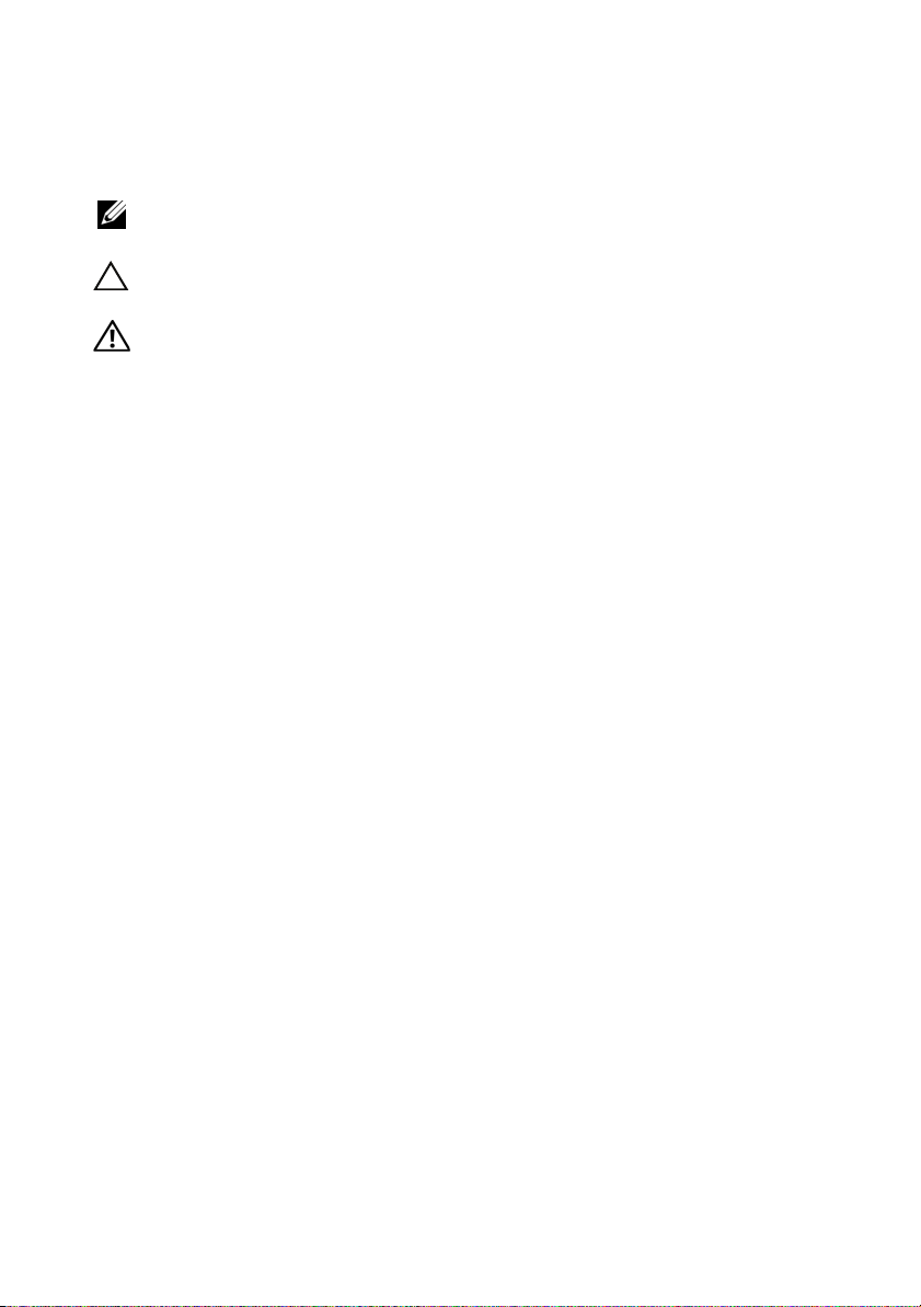
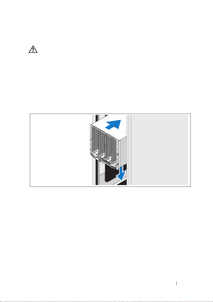
Installing the Rails and System in a Rack
Assemble the rails and install the system in the rack following the
safety instructions and the rack installation instructions provided
with your enclosure.
Getting Started With Your System 3
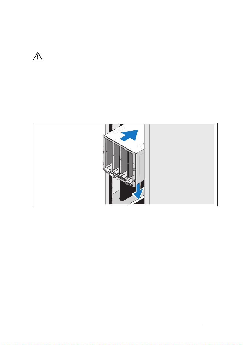
Installing the Blades
Beginning at the top, slide the modules into the enclosure from left to right.
When the blade is securely installed, the handle returns to the closed position.
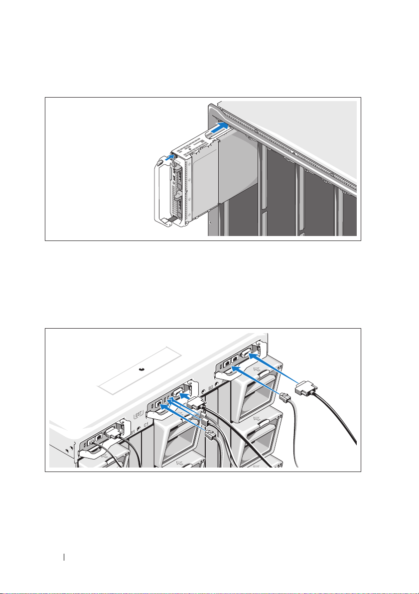
Connecting the CMC and KVM Modules
Connect the serial cable and network cable(s) from the management
system to the CMC module. If a second, optional CMC module is installed,
connect it as well.
Connect the keyboard, mouse, and monitor to the optional iKVM module.
4 Getting Started With Your System
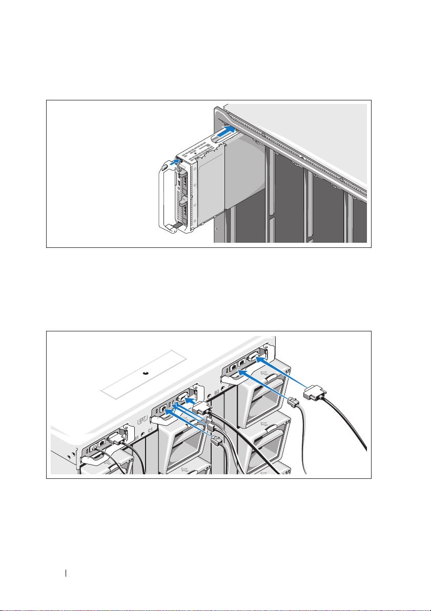
Connecting the System to Power
Connect the system’s power cables to the system power supplies.
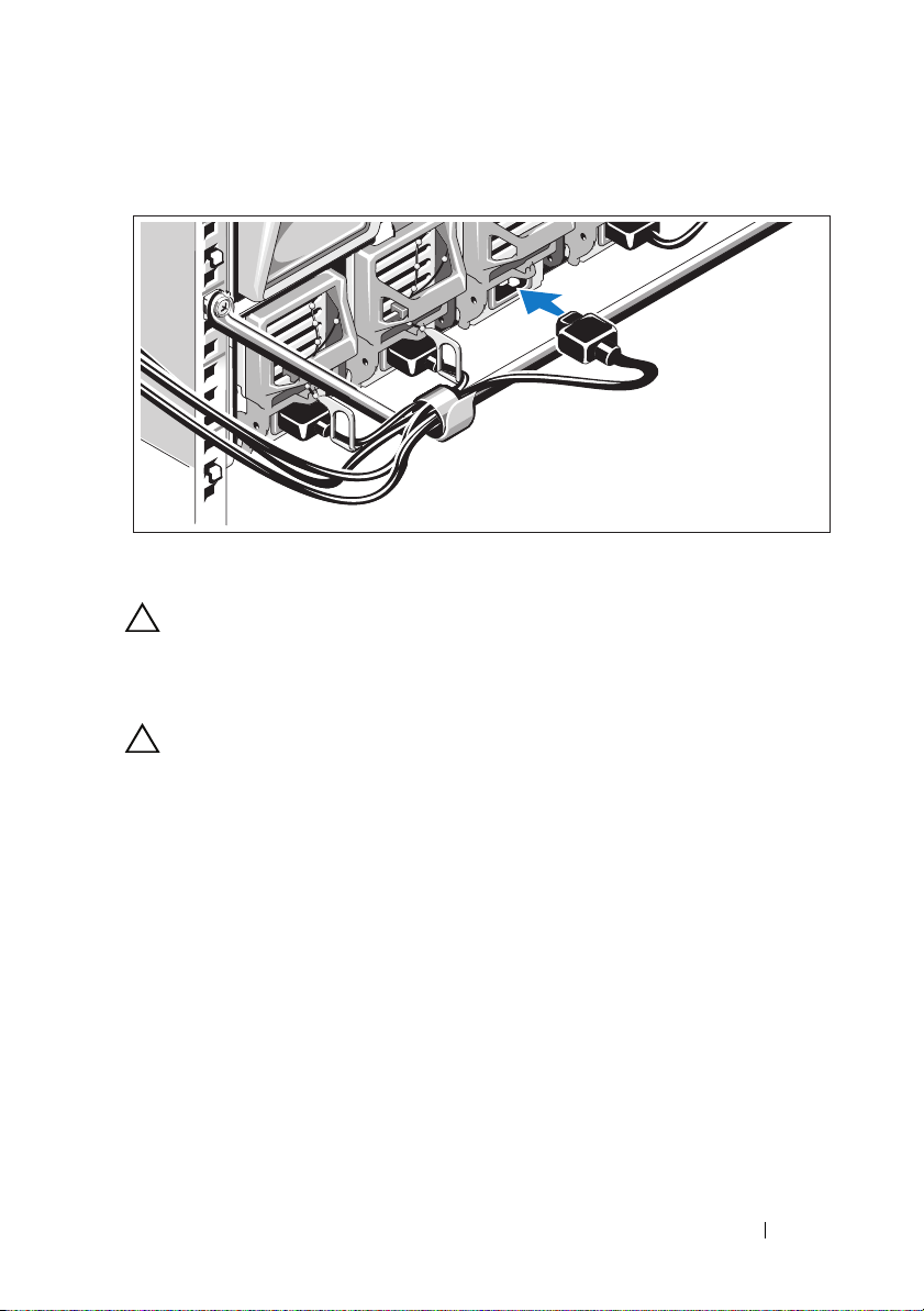
CAUTION: To prevent the power cables from being disconnected accidentally,
use the plastic clip on each power supply to secure the power cable to the
power supply, and use the Velcro strap to secure the cable to the strain-relief bar.
Plug the other end of the power cables into a power distribution unit (PDU).
CAUTION: Do not plug the power cables directly into a power outlet; you must
use a PDU. For optimal system functionality, a minimum of three power supplies
are required.
Getting Started With Your System 5

Turning On the System
Press the power button on the enclosure. The power indicator should light.
NOTE: Once you have connected the system to the power supplies, there may
be a minimal delay before you can turn on your system.
Turning On the Blades
Press the power button on each blade, or power on the blades using
the systems management software.
6 Getting Started With Your System

Complete the Operating System Setup
If you purchased a preinstalled operating system, see the operating system
documentation that ships with your system. To install an operating system
for the first time, see the installation and configuration documentation
for your operating system. Be sure the operating system is installed before
installing hardware or software not purchased with the system.
Supported Operating Systems
Operating System
Citrix® XenServer 5.5
Citrix® XenServer 5.6
Microsoft® Windows
®
2008 Hyper-V Server
Server
Microsoft Windows® Essential
Business Server 2008 Standard
and Premium Editions
Microsoft Windows HPC
Server 2008 (x64)
Microsoft Windows
Server 2008 Standard and
Enterprise (x86) Editions
Microsoft Windows Web
Server 2008 (x86) Edition
Microsoft Windows Web
Server 2008 (x86) Edition
with SP2
Microsoft Windows
Server 2008 Standard and
Enterprise (x86)
Editions with SP2
Microsoft Windows
Server 2008 Standard,
Enterprise, and
Datacenter (x64) Editions
Microsoft Windows Web
Server 2008 (x64) Edition
M710HD
M910 M905 M805 M710 M610 M610x M605
Getting Started With Your System 7

Operating System
Microsoft Windows Web
Server 2008 (x64) Edition
with SP2
Microsoft Windows Server 2008
R2 Standard, Enterprise, and
Datacenter (x64) Editions
Microsoft Windows Server 2003
Standard and Enterprise
Editions
Microsoft Windows Server 2003
Web Edition
Microsoft Windows
Server 2003
Standard Enterprise, and Web
Editions with SP1 and later
Microsoft Windows Server 2003
R2 Standard and Enterprise
(x86) Editions
Microsoft Windows Server 2003
Standard and Enterprise (x64)
Editions
Microsoft Windows
Server 2003 R2 Standard and
Enterprise (x64) Editions
Microsoft Windows
Server 2003 R2 Datacenter
(x64) Edition
Microsoft Windows
Server 2003 R2 Standard,
Enterprise, and Datacenter
(x64) Editions with SP2
Red Hat® Enterprise Linux®
AS, ES, and WS (version 4.0)
Update 5 (x86)
Red Hat Enterprise Linux AS,
ES, and WS (version 4.0)
Update 5 (x86_64)
Red Hat Enterprise Linux AS
and ES (version 4.7) (x86)
Red Hat Enterprise Linux AS
and ES (version 4.7) (x86_64)
M710HD
M910 M905 M805 M710 M610 M610x M605
8 Getting Started With Your System

Operating System
Red Hat Enterprise Linux AS
and ES (version 4.8) (x86)
Red Hat Enterprise Linux AS
and ES (version 4.8) (x86_64)
Red Hat Enterprise Linux
(version 5.0) (x86)
Red Hat Enterprise Linux
(version 5.0) (x86_64)
Red Hat Enterprise Linux
(version 5.2) (x86)
Red Hat Enterprise Linux
(version 5.5) (x86)
Red Hat Enterprise Linux
(version 5.5) (x86_64)
SUSE® Linux Enterprise
Server 9 (x86_64) SP3
SUSE Linux Enterprise
Server 10 (x86_64)
SUSE Linux Enterprise
Server 10 (x86_64) SP3
SUSE Linux Enterprise
Server 11 (x86_64)
Solaris® 10 (x86_64)
Solaris 10 Update 7
VMware® ESX version 3.0
VMware ESX version 3.0.2
Update 1
VMware ESX version 3.5
VMware ESX version 4.0
Update 1
VMware ESXi version 4.0
Update 1
—Supported
M710HD
M910 M905 M805 M710 M610 M610x M605
NOTE: For the latest information on supported operating systems for all PowerEdge
systems, see dell.com/ossupport.
Getting Started With Your System 9

Other Information You May Need
WARNING: Before performing the following procedure, review the safety
instructions that came with the system.
•The
•
•The
• Dell systems management application documentation provides
Configuration Guide
enclosure and the blades.
Rack Installation Instructions
how to install your system into a rack.
Hardware Owner’s Manual
features and describes how to troubleshoot the system and install or
replace system components.
information about installing and using the systems management software.
NOTE: Always check for updates on support.dell.com/manuals and read the
updates first because they often supersede information in other documents.
provides information on configuring the system
included with your rack solution describes
provides information about system
Obtaining Technical Assistance
If you do not understand a procedure in this guide or if the system does not
perform as expected, see your Hardware Owner’s Manual. Dell™ offers
comprehensive hardware training and certification. See www.dell.com/training
for more information. This service may not be offered in all locations.
10 Getting Started With Your System

Technical Specifications
Blade Specifications
Processor
Processor type
PowerEdge M910
PowerEdge M905
PowerEdge M805
PowerEdge M710HD,
M710, M610, M610x
PowerEdge M605
PowerEdge M600
Memory
Architecture
PowerEdge M910
PowerEdge M905,
M805, M605
PowerEdge M710HD
PowerEdge M710,
M610, M610x
PowerEdge M600
Two or four Intel® Xeon® 7000 series processors
(up to eight-core processors)
Four dual- or quad-core AMD® Opteron® 8000 series
processors
Two dual- or quad-core AMD Opteron 2000 series
processors
One or two dual-, quad-, or six-core Intel Xeon 5000
series processors
One or two dual- or quad-core AMD Opteron 2000
series processors
One or two dual- or quad-core Intel Xeon processors
DDR3 memory modules,
rated for 1066-MHz operation
DDR2 memory modules,
rated for 677-MHz operation
DDR3 and DDR3L single-, dual-, and quad-rank
memory modules, rated for1066 and 1333-MHz
800-, 1066-, or 1333-MHz DDR3 single- or
dual-ranked registered DIMMs (RDIMMs) or
unbuffered DIMMs (UDIMMs)
or
800- or 1066-MHz DDR3 quad-ranked registered
DIMMs (RDIMMs) or unbuffered DIMMs
(UDIMMs)
FBD memory modules, rated for 677-MHz operation
Getting Started With Your System 11

Memory (continued)
Memory module sockets
PowerEdge M910
PowerEdge M905
PowerEdge M805
PowerEdge M710HD
PowerEdge M710
PowerEdge M610x, M610
PowerEdge M605, M600
Memory module capacities
PowerEdge M910
PowerEdge M905, M805,
PowerEdge M710HD
PowerEdge M710,
M610x, M610
PowerEdge M605, M600
Minimum RAM
PowerEdge M910
PowerEdge M905
PowerEdge M805
PowerEdge M710D
PowerEdge M710,
M610x, M610
PowerEdge M600, M605
32 240-pin sockets
24 240-pin sockets
16 240-pin sockets
18 240-pin sockets
18 240-pin sockets
12 240-pin sockets
Eight 240-pin sockets
1 GB, 2 GB, 4 GB, 8 GB, and 16 GB RDIMMs
1 GB, 2 GB, 4 GB, and 8 GB
1 GB, 2 GB, 4 GB, 8 GB, and 16 GB
RDIMMs and LV DIMMs
2 GB, 4 GB, 8 GB, and 16 GB RDIMMs;
1 GB and 2 GB UDIMMs
512 MB, 1 GB, 2 GB, 4 GB, and 8 GB
4 GB
8 GB (Eight 1-GB memory modules)
4 GB (Four 1-GB memory modules)
4 GB
One 1-GB memory module (one-processor systems)
or two 1-GB memory modules (two-processor
systems)
1 GB (two 512-MB memory modules)
12 Getting Started With Your System

Memory (continued)
Maximum RAM
PowerEdge M910
PowerEdge M905
PowerEdge M805
PowerEdge M710HD
PowerEdge M710
PowerEdge M610, M610x
PowerEdge M600, M605
Drives
Hard Drives
PowerEdge M910
PowerEdge M905, M805
PowerEdge M710HD
PowerEdge M710
512 GB
192 GB
128 GB
144 GB (dual-rank DIMMs) or 192 GB
(quad-rank DIMMs)
192 GB (12 16-GB RDIMMs);
36 GB (18 2-GB UDIMMs)
192 GB (12 16-GB RDIMMs);
24 GB (12 2-GB UDIMMs)
64 GB
Up to two 2.5-inch SAS hard-disk drives support
through value RAID or performance RAID
storage card.
or
Up to two 2.5-inch SSD hard-disk drives support
through value RAID or performance RAID
storage card.
Up to two 2.5-inch SAS hard-disk drives support
through value RAID or performance RAID
storage card.
Up to two 2.5-inch SAS hard-disk drives support
through PERC H200 embedded storage controller.
or
Up to two 2.5-inch SSD hard-disk drives support
through PERC H200 embedded storage controller.
Up to four 2.5-inch SAS hard-disk drives support
through value RAID or performance RAID
storage card.
Getting Started With Your System 13

Drives (continued)
PowerEdge M600,
M610x, M610
PowerEdge M605
One 2.5-inch SATA hard-disk drive support through
non-RAID, value RAID, or performance RAID
storage card.
or
Two 2.5-inch SATA hard-disk drives support through
value RAID or performance RAID storage card.
or
One solid-state disk (SSD) hard drive support
through non-RAID storage card.
or
Up to two SAS hard-disk drives support through value
RAID or performance RAID storage card.
Up to two SATA hard-disk drives support through
value RAID or performance RAID storage card.
or
Up to two solid-state disk (SSD) hard drives support
through non-RAID storage card.
or
Up to two SAS hard-disk drives support through value
RAID or performance RAID storage card.
NOTE: For all modular systems, SAS and SATA hard
drives cannot be mixed within a blade.
NOTE: Hot-plug operation is supported if an optional
RAID controller card is installed.
Connectors
External
USB
PowerEdge M910,
M805, M905, M710
PowerEdge M710HD,
M610x, M610, M605,
M600
Three 4-pin, USB 2.0 compliant
Two 4-pin, USB 2.0 compliant
14 Getting Started With Your System

Connectors (continued)
Internal
Internal Secure Digital
(SD) module (PowerEdge
M910, M805, M905,
M710HD, M710,
M610x, M610)
Internal Secure Digital
(SD) vFlash module
(PowerEdge M910,
M710HD, M710,
M610x, M610)
USB key (PowerEdge
M910, M710HD,
M710, M610x, M610)
PCIe Expansion Solution
PowerEdge M610x Supports two single-wide or one double-wide
Mezzanine Cards
PowerEdge M910 Up to four PCIe Gen 2 x8 mezzanine card slots,
PowerEdge M905, M805 Up to four PCIe Gen 1 x8 mezzanine card slots,
PowerEdge M710HD Up to two PCIe Gen 2 x8 mezzanine card slots,
PowerEdge M710 Up to four PCIe Gen 2 mezzanine card slots (three x8
One optional flash memory card slot
with the internal SD module.
One optional vFlash memory card slot for
use with the iDRAC Enterprise support.
One internal USB key connector.
full length standard PCIe card.
supporting dual-port Gb Ethernet, 10 Gb Ethernet,
FC8 Fibre Channel, or Infiniband mezzanine cards.
supporting dual-port Gb Ethernet, 10 Gb Ethernet,
FC8 or FC4 Fibre Channel, or 4x DDR Infiniband
mezzanine cards.
supporting dual-port and quad-port Gb Ethernet,
10 Gb Ethernet, FC8 or FC4 Fibre Channel,
or 4x DDR Infiniband mezzanine cards.
and one x4 lane width), supporting dual-port Gb
Ethernet, 10 Gb Ethernet, FC8 or FC4 Fibre
Channel, or 4x DDR Infiniband mezzanine cards.
Getting Started With Your System 15

Mezzanine Cards (continued)
PowerEdge M610x, M610 Up to two PCIe Gen 2 x8 mezzanine card slots,
supporting dual-port Gb Ethernet, 10 Gb Ethernet,
FC8 or FC4 (M610 only) Fibre Channel, or 4x DDR
Infiniband mezzanine cards.
PowerEdge M605, M600 Up to two PCIe x8 mezzanine card slots, supporting
dual-port Gb Ethernet, 10 Gb Ethernet, FC8 or
FC4 Fibre Channel, or 4x DDR Infiniband
mezzanine cards.
Embedded Ethernet Controllers
PowerEdge M910, M905,
M805, M710HD, M710
PowerEdge M610x, M610 Two Ethernet ports with TOE and iSCSI boot
PowerEdge M605, M600 Two Ethernet ports with TOE and iSCSI boot
Video Controller
PowerEdge M905, M805,
M605, M600
PowerEdge M910,
M710HD, M710, M610x,
M610
Four Ethernet ports with TOE and iSCSI boot
support, provided by two integrated dual-port
Broadcom 5709S Ethernet controllers.
support, provided by one integrated dual-port
Broadcom 5709S Ethernet controller.
support, provided by two integrated Broadcom 5708S
controllers.
ATI RN50 video controller. 32 MB video memory.
Matrox G200 video controller. 8 MB video memory.
Physical
PowerEdge M910
Height
Width
Depth
Weight (maximum
configuration)
38.5cm (15.2 in)
5 cm (2 in)
48.6 cm (19.2 in)
13.1 kg (29 lb)
16 Getting Started With Your System

Physical (continued)
PowerEdge M905, M805,
M710, M610x
Height
Width
Depth
Weight (maximum
configuration)
PowerEdge M710HD
Height
Width
Depth
Weight (maximum
configuration)
PowerEdge M605, M600
Height
Width
Depth
Weight (maximum
configuration)
38.5cm (15.2 in)
5 cm (2 in)
48.6 cm (19.2 in)
11.1 kg (24.5 lb)
18.9 cm (7.4 in)
5 cm (2 in)
48.6 cm (19.2 in)
7.4 kg (16.3 lb)
18.9 cm (7.4 in)
5 cm (2 in)
48.6 cm (19.2 in)
5.2–6.4 kg (11.5–14.0 lb)
Battery
NVRAM backup battery CR 2032 3.0-V lithium coin cell
Getting Started With Your System 17

System Enclosure Specifications
Physical
Height 44.0 cm (17.3 in)
Width 44.7 cm (17.6 in)
Depth 75.5 cm (29.7 in)
Weight (maximum
configuration)
Weight (empty) 44.6 kg (98.1 lb)
Power Supply Module
AC/DC power supply (per power supply)
Wa t ta g e
Connector
Heat dissipation
Maximum inrush
current
System Voltage Requirements 14.4 A, 200–240 VAC, 50/60 Hz
178.3 kg (392.2 lb)
2360 W and 2700 W
IEC C20
1205 BTU/hr. maximum
Under typical line conditions and over the entire
system ambient operating range, the inrush current
may reach 55 A per power supply for 10 ms or less.
Optional Avocent iKVM Module
Externally accessible connectors
USB
ACI port
Video
Two 4-pin, USB 2.0-compliant connectors for
keyboard and mouse support
RJ-45
15-pin VGA
18 Getting Started With Your System

Chassis Management Controller Module
Externally accessible connectors
Remote management
Serial
Video
Battery CR 2032 3.0-V lithium ion coin cell
Enclosure Control Panel
Externally accessible connectors
USB
Video
LCD Panel
Feature s
Two dedicated 10/100/1000 Mb RJ-45 (for integrated
Ethernet remote access controller). Gb port connects
to the external management network. STK port
allows CMCs in adjacent enclosures to be daisy
chained.
9-pin, DTE, 16550-compatible
15-pin VGA
Two 4-pin, USB 2.0-compliant connectors for
keyboard and mouse support
15-pin VGA
Four cursor control keys, one select key, LCD screen
Getting Started With Your System 19

I/O Module Specifications
For information about the I/O modules and pass-through modules supported
on your enclosure, see the Dell PowerEdge M1000e Systems Configuration
Guide at support.dell.com/manuals.
Environmental
NOTE: For additional information about environmental measurements for specific
system configurations, see dell.com/environmental_datasheets. The system is
not for use in an office environment.
Temperature
Operating
Storage
Relative humidity
Operating
Storage
Maximum vibration
Operating
Storage
Maximum shock
Operating
Storage
Altitude
Operating
Storage
10° to 35°C (50° to 95°F)
NOTE: Decrease the maximum temperature
by 1°C (1.8°F) per 300 m (985 ft) above 900 m (2955 ft).
–40° to 65°C (–40° to 149°F)
8% to 85% (noncondensing) with a maximum
humidity gradation of 10% per hour
5% to 95% (noncondensing)
0.26 Grms at 10–350 Hz for 15 min
1.54 Grms at 10–250 Hz for 15 min
One shock pulse in the positive z axis (one pulse
on each side of the system) of 41 G for up to 2 ms
Six consecutively executed shock pulses in the
positive and negative x, y, and z axes (one pulse
on each side of the system) of 71 G for up to 2 ms
–16 to 3,048 m (–50 to 10,000 ft)
–16 to 10,600 m (–50 to 35,000 ft)
20 Getting Started With Your System

Systèmes Dell™ PowerEdge™
M1000e, M910, M905, M805,
M710HD, M710, M610x, M610,
M605 et M600
Guide de mise en route
Modèle BMX01, série HHB, série FHB

Remarques, précautions et avertissements
REMARQUE : Une REMARQUE indique des informations importantes qui peuvent
vous aider à mieux utiliser votre ordinateur.
PRÉCAUTION : Une PRÉCAUTION vous avertit d'un risque d'endommagement
du matériel ou de perte de données en cas de non-respect des instructions.
AVERTISSEMENT: Un AVERTISSEMENT indique un risque d'endommagement
du matériel, de blessure corporelle ou de mort.
____________________
Les informations contenues dans ce document sont sujettes à modification sans préavis.
© 2010 Dell Inc. Tous droits réservés.
La reproduction de ce document de quelque manière que ce soit sans l'autorisation écrite de Dell Inc.
est strictement interdite.
Marques mentionnées dans ce document : Dell, le logo DELL, et PowerEdge sont des marques
de Dell Inc. ; Citrix est une marque de Citrix Systems, Inc. et/ou d'une ou de plusieurs de ses filiales,
et peut être déposée auprès du Patent and Trademark Office aux États-Unis et d'organismes similaires
dans d'autres pays ; Intel est une marques déposée d'Intel Corporation aux États-Unis et dans d'autres
pays ; Microsoft, Windows et Windows Server sont des marques ou des marques déposées de
Microsoft Corporation aux États-Unis et/ou dans d'autres pays ; Red Hat et Red Hat Enterprise Linux
sont des marques déposées de Red Hat, Inc. aux États-Unis et dans d'autres pays ; SUSE est une marque
déposée de Novell, Inc. aux États-Unis et dans d'autres pays ; VMware est une marque ou une marque
déposée (les “marques”) de VMware, Inc. aux États-Unis et/ou dans d'autres juridictions ; Solaris est
une marque de Sun Microsystems, Inc. aux États-Unis et dans d'autres pays.
D'autres marques commerciales et noms de marque peuvent être utilisés dans ce document pour faire
référence aux entités se réclamant de ces marques et de ces noms ou de leurs produits. Dell Inc. dénie
tout intérêt propriétaire vis-à-vis des marques et des noms de marque autres que les siens.
Modèle BMX01, série HHB, série FHB
Mars 2010 N/P W7NC1 Rév. A00
Installation et configuration
AVERTISSEMENT: Avant d'exécuter la procédure ci-dessous,
lisez les consignes de sécurité fournies avec le système.
Cette section décrit les étapes à exécuter lors de la configuration initiale
du système.
Déballage du système
Sortez le système de son emballage et identifiez chaque élément.
Installation des rails et du système dans un rack
Assemblez les rails et installez le système dans le rack en suivant les consignes
de sécurité et les instructions d'installation du rack fournies avec votre
châssis.
Guide de mise en route 23
Installation des serveurs lames
Insérez les modules dans le châssis en commençant par le haut et en procédant
de gauche à droite. Lorsqu'un serveur lame est correctement installé, la poignée
revient en position fermée.
Connexion des modules CMC et KVM
Connectez le ou les câbles série et réseau entre le système de gestion et
le module CMC. Si un second module CMC en option est installé,
connectez-le également.
Connectez le clavier, la souris et le moniteur au module iKVM en option.
24 Guide de mise en route

Branchement du système sur le secteur
Branchez les câbles d'alimentation du système aux blocs d'alimentation
de celui-ci.
PRÉCAUTION : Pour éviter que les câbles d'alimentation ne soient débranchés
accidentellement, utilisez le clip en plastique situé sur chaque bloc
d'alimentation pour y fixer le câble. Utilisez également la bande Velcro permettant
de maintenir le câble sur la barre de retenue.
Branchez l'autre extrémité des câbles d'alimentation dans une unité
de distribution d'alimentation.
PRÉCAUTION : Ne branchez pas les câbles d'alimentation directement sur une
prise de courant. Il est impératif d'utiliser une unité de distribution d'alimentation.
Pour un fonctionnement optimal du système, utilisez au moins trois blocs
d'alimentation.
Guide de mise en route 25
 Loading...