

Page 1
CAUTION: A CAUTION indicates either potential damage to hardware or loss of data and tells you how to avoid the
problem.
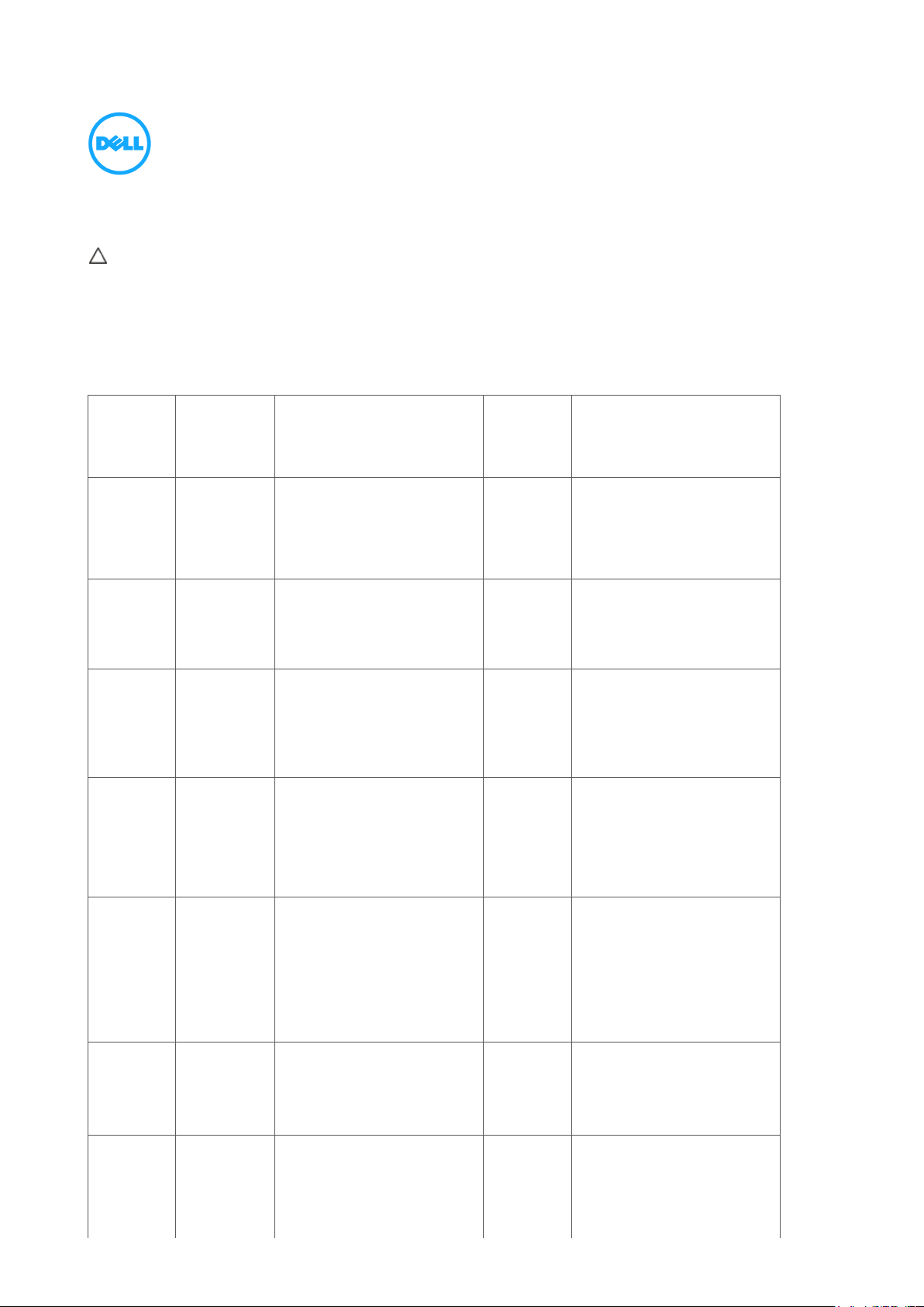
Description
Reference
Designator
Volatility Description
User
Accessible
for external
data
Remedial Action (Action
necessary to prevent loss of
data)
Embedded
Flash in
embedded
controller
MEC5075
U38
256K and 2K byte of
embedded Flash memory for
embedded controller BIOS
code, asset tag and BIOS
passwords
No
N/A
Panel
EEDID
EEPROM
Part of panel
assembly
Non Volatile memory 64K
bytes. Stores panel
manufacturing information,
display configuration data
No
N/A
System
BIOS
U1,U2
Non Volatile memory, 64Mbit
(8MB), 32Mbit (4MB) System
BIOS and Video BIOS for
basic boot operation, PSA (on
board diags), PXE diags.
No
N/A
System
Memory –
DDR3L
memory
Connectors
JDIMM1
and
JDIMM2
Volatile memory in OFF state
(see state definitions later in
text) One or both modules will
be populated. System memory
size will depend on SoDIMM
modules and will be between
1GB and 8GB
Yes
Power off system
System
memory
SPD
EEPROM
On memory
SoDIMM(s)
– one or two
present
Non-Volatile memory 2Kbit
(256 bytes). One device
present on each SoDIMM.
Stores memory manufacturer
data and timing information
for correct operation of system
memory.
No
N/A
RTC
CMOS –
BBRAM
(battery
backed up)
UC1
Non Volatile memory 256
bytes. Stores CMOS
information
No
Remove the on-board coin cell
battery
Video
memory –
frame
buffer
UMA
architectureuses system
DDR3L.
Discrete
graphics
Volatile memory in off state.
2GB DDR3L for Discrete
Graphics systems. UMA uses
main system memory size
allocated out of main memory.
No
Enter S3-S5 state described
below.
Statement of Volatility – Dell Latitude™ E5440/E5540
The Dell Latitude™ E5440/E5540 contains both volatile and non-volatile (NV) components. Volatile components lose their
data immediately after power is removed from the component. Non-volatile (NV) components continue to retain their data
even after power is removed from the component. The following NV components are present on the Dell Latitude™
E5440/E5540 system board.
Table 1. List of Non-Volatile Components on System Board
Month yyyy
Page 2
Description
Reference
Designator
Volatility Description
User
Accessible
for external
data
Remedial Action (Action
necessary to prevent loss of
data)
systems use
DDR3L
(UV4-UV7)
for frame
buffer
DP hub
FW
U7
This is volatile memory for DP
hub FW (1Mbit).
No
N/A
mSATA
JMINI2
mSATA module would share
with WWAN module on full
size mini-card. Non Volatile
memory (SSD)
Yes
Low level format
TPM
Controller
U25
Non Volatile memory, 2K bits
(256 bytes) ROM
No
N/A
Hard drive
User
replaceable
Non Volatile magnetic media,
various sizes in GB
yes
Low level format
CDROM/RW/
DVD/
DVD+RW/
Diskette
Drives
User
replaceable
Non Volatile optical media.
Yes
Low level format/erase
CAUTION: All other components on the system board lose data if power is removed from the system. Primary power
loss (unplugging the power cord and removing the battery) destroys all user data on the memory (DDR3L,
1333/1600MHz). Secondary power loss (removing the on-board coin-cell battery) destroys system data on the system
configuration and time-of-day information.
All other components on the motherboard will lose data once power is removed from the system. Primary power loss
(Unplug the power cord and remove the battery) will destroy all user data on the memory (DDR3L, 1333/1600MHz).
Secondary power loss (removing the on board coin-cell battery) will destroy system data on the system configuration
and time-of-day information.
In addition, to clarify memory volatility and data retention in situations where the system is put in different ACPI power
states the following is provided (those ACPI power states are S0, S1, S3, S4 and S5):
S0 state is the working state where the dynamic RAM is maintained and is read/write by the processor.
S1 state is a low wake-up latency sleeping state. In this state, no system context is lost (CPU or chip set) and hardware
maintains all system contexts.
S3 is called “suspend to RAM” state or stand-by mode. In this state the dynamic RAM is maintained. Dell systems will
be able to go to S3 if the OS and the peripherals used in the system supports S3 state. Linux, Win7 and Win8 support
S3 state.
S4 is called “suspend to disk” state or “hibernate” mode. There is no power. In this state, the dynamic RAM is not
maintained. If the system has been commanded to enter S4, the OS will write the system context to a non-volatile
storage file and leave appropriate context markers. When the system is coming back to the working state, a restore file
from the non-volatile storage can occur. The restore file has to be valid. Dell systems will be able to go to S4 if the OS
and the peripherals support S4 state. Win7 and Win8 support S4 state.
S5 is the “soft” off state. There is no power. The OS does not save any context to wake up the system. No data will
remain in any component on the system board, i.e. cache or memory. The system will require a complete boot when
awakened. Since S5 is the shut off state, coming out of S5 requires power on which clears all registers.
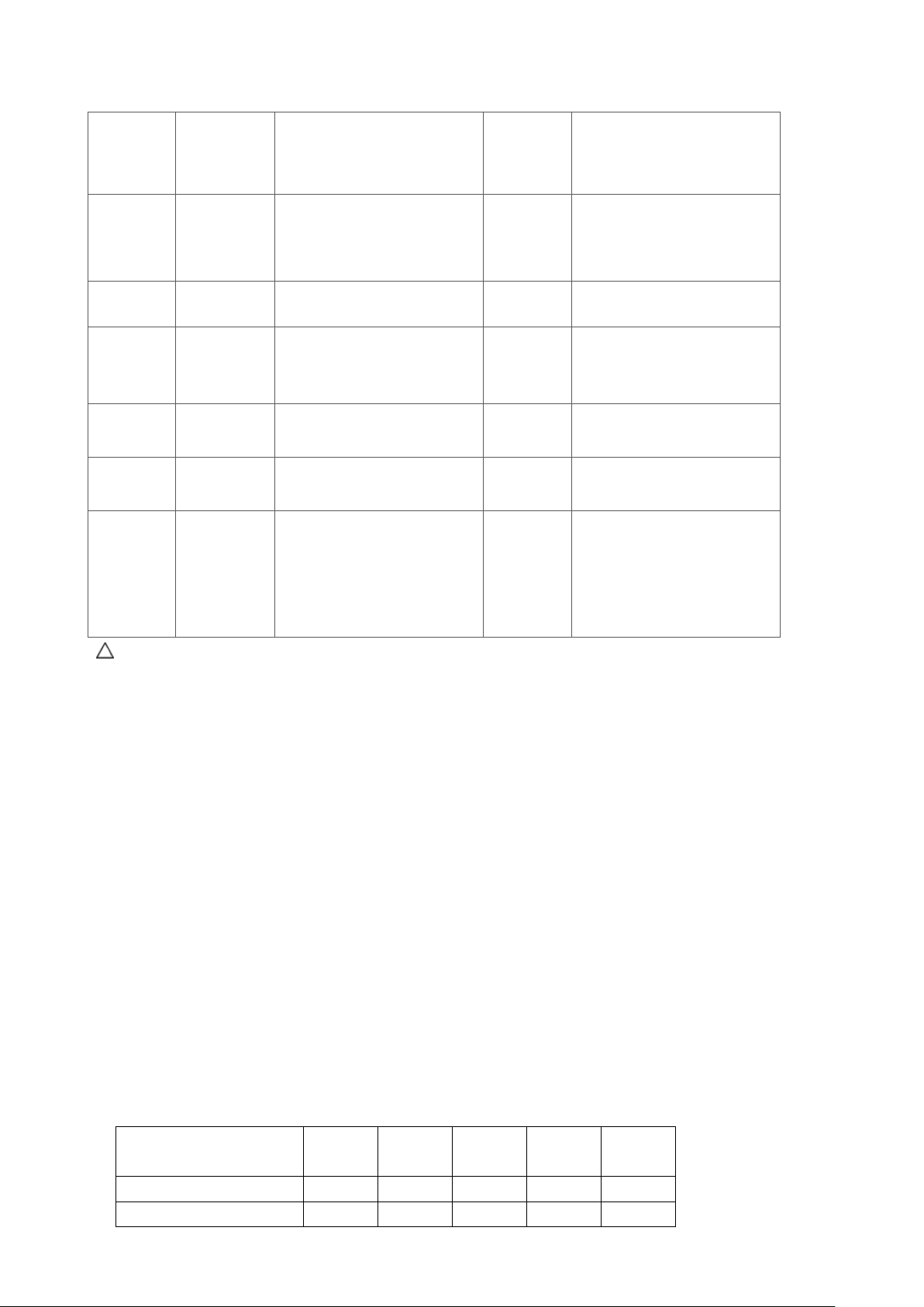
The following table shows all the states supported by Dell Latitude™E5440/E5540: Model Number
Model Number
S0
S1
S3
S4
S5
Dell Latitude™ E5440
X X X X
Dell Latitude™ E5540
X X X X
Page 3

______________
© 2012 Dell Inc.
Trademarks used in this text: Dell™, the DELL logo, Dell Precision™, OptiPlex™, Latitude™, PowerEdge™, PowerVault™, PowerConnect™,
OpenManage™, EqualLogic™, KACE™, FlexAddress™ and Vostro™ are trademarks of Dell Inc. Intel®, Pentium®, Xeon®, Core™ and Celeron® are
registered trademarks of Intel Corporation in the U.S. and other countries. AMD® is a registered trademark and AMD Opteron™, AMD Phenom™, and
AMD Sempron™ are trademarks of Advanced Micro Devices, Inc. Microsoft®, Windows®, Windows Server®, MS-DOS® and Windows Vista® are
either trademarks or registered trademarks of Microsoft Corporation in the United States and/or other countries. Red Hat Enterprise Linux® and
Enterprise Linux® are registered trademarks of Red Hat, Inc. in the United States and/or other countries. Novell® is a registered trademark and SUSE ™
is a trademark of Novell Inc. in the United States and other countries. Oracle® is a registered trademark of Oracle Corporation and/or its affiliates. Citrix®,
Xen®, XenServer® and XenMotion® are either registered trademarks or trademarks of Citrix Systems, Inc. in the United States and/or other countries.
VMware®, Virtual SMP®, vMotion®, vCenter®, and vSphere® are registered trademarks or trademarks of VMWare, Inc. in the United States or other
countries.
 Loading...