

Dell latitude c510, latitude c610 schematic

Dell Latitude C610/C510 Service Manual
Dell™ Latitude™ C610/C510 Service
Manual
Before You Begin
System Components
Hard Drive
Memory Modules, Mini PCI Card, and Modem
Keyboard
Display Assembly, Display Latch, and Hinge Covers
Palm Rest
Microprocessor Thermal Cooling Assembly
Microprocessor Module
Hybrid Cooling Fan
Reserve Battery
Flashing the BIOS
Speaker Assemblies
System Board
Battery and Module Bay Latches
Pin Assignments for I/O Connectors
Notes, Notices, and Cautions
NOTE: A NOTE indicates important information that helps you make better use
of your computer.
NOTICE: A NOTICE indicates either potential damage to hardware or loss of
data and tells you how to avoid the problem.
CAUTION: A CAUTION indicates a potential for property damage,
personal injury, or death.
file:///F|/Service%20Manuals/Dell/Latitude/c510-610/index.htm (1 of 2) [2/28/2004 7:55:37 AM]

Dell Latitude C610/C510 Service Manual
Trademarks used in this text: Dell, the DELL logo, and Latitude are trademarks of Dell Computer
Corporation; Intel is a registered trademark of Intel Corporation; Microsoft and Windows are registered
trademarks of Microsoft Corporation.
Other trademarks and trade names may be used in this document to refer to either the entities
claiming the marks and names or their products. Dell Computer Corporation disclaims any proprietary
interest in trademarks and trade names other than its own.
January 2002 Rev. A01
file:///F|/Service%20Manuals/Dell/Latitude/c510-610/index.htm (2 of 2) [2/28/2004 7:55:37 AM]
Before You Begin: Dell Latitude C610/C510 Service Manual
Back to Contents Page
Before You Begin
Dell™ Latitude™ C610/C510 Service Manual
Preparing to Work Inside the Computer
Recommended Tools
Screw Identification
Preparing to Work Inside the Computer
CAUTION: Before working inside your computer, read "Safety and EMC
Instructions: Portable Computers" in your System Information Guide.
NOTICE: Only a certified service technician should perform repairs on your
computer. Damage due to servicing that is not authorized by Dell is not covered
by your warranty.
NOTICE: To avoid damaging the computer, perform the following steps before
you begin working inside the computer.
1. Make sure that the work surface is clean to prevent scratching the computer
cover.
2. Save any work in progress and close all open programs.
3. Turn off the computer and all attached devices.
NOTE: Make sure the computer is turned off and not in suspend-to-disk or
hibernate mode. If you cannot shut down the computer using the computer
operating system, press and hold the power button for 4 seconds.
4. Make sure the computer is undocked.
5. Disconnect the computer from the electrical outlet.
file:///F|/Service%20Manuals/Dell/Latitude/c510-610/begin.htm (1 of 6) [2/28/2004 7:55:44 AM]

Before You Begin: Dell Latitude C610/C510 Service Manual
6. To avoid possible damage to the system board, wait 10 to 20 seconds and then
disconnect any attached devices.
7. Disconnect all other external cables from the computer.
8. Remove any installed PC Cards or plastic blanks from the PC Card slot.
9. Close the display and turn the computer upside down on a flat work surface.
NOTICE: To avoid damaging the system board, you must remove the main
battery and secondary battery (if present) before you service the computer.
10. Remove the primary battery from the battery bay and the secondary battery
from the module bay, if a secondary battery is in use.
11. Remove any installed device in the module bay.
12. To dissipate any static electricity while you work, use a wrist grounding strap or
periodically touch an unpainted metal surface.
13. Handle components and cards with care. Do not touch the components or
contacts on a card. Hold a card by it edges or by its metal mounting bracket.
Hold a component such as a microprocessor by its edges, not by its pins.
Recommended Tools
The procedures in this manual require the following tools:
● #1 magnetized Phillips screwdriver
● ¼-inch flat-blade screwdriver
● Small plastic scribe
● Microprocessor extractor
● Flash BIOS update program floppy disk or CD
file:///F|/Service%20Manuals/Dell/Latitude/c510-610/begin.htm (2 of 6) [2/28/2004 7:55:44 AM]
Before You Begin: Dell Latitude C610/C510 Service Manual
Computer Orientation
1 back
2 right
3 front
4 left
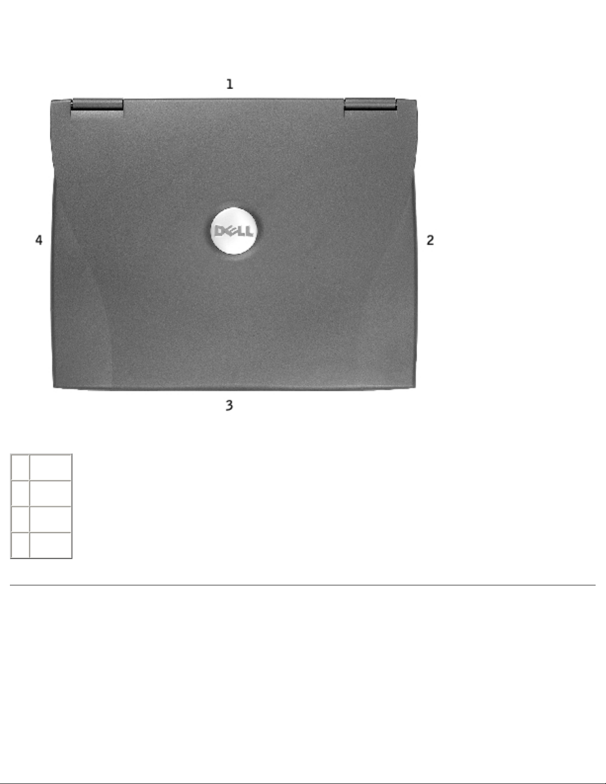
Screw Identification
When you are removing and replacing components, photocopy the placemat as a tool
to lay out and keep track of the screws. The placemat provides the number of screws
and their sizes.
file:///F|/Service%20Manuals/Dell/Latitude/c510-610/begin.htm (3 of 6) [2/28/2004 7:55:44 AM]
Before You Begin: Dell Latitude C610/C510 Service Manual
Screw Identification
NOTICE: When reinstalling a screw, you must use a screw of the correct
diameter and length. Make sure that the screw is properly aligned with its
corresponding hole, and avoid over tightening.
Hard Drive Door:
(1 each)
Keyboard to
Bottom Case:
(5 each)
Display Bezel:
(6 each)
Rubber Screw Covers (6 each)
Hinge Bracket to Bottom Case:
(5 each)
file:///F|/Service%20Manuals/Dell/Latitude/c510-610/begin.htm (4 of 6) [2/28/2004 7:55:44 AM]

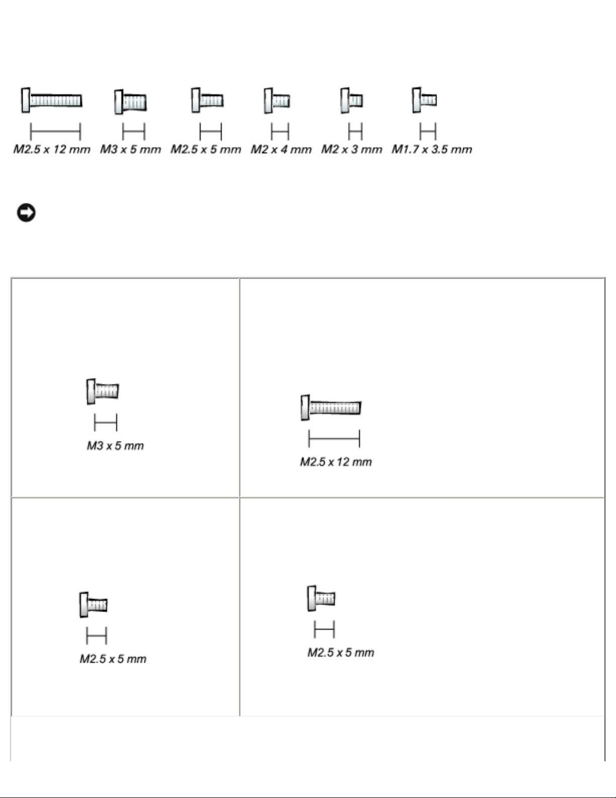
Before You Begin: Dell Latitude C610/C510 Service Manual
Display Assembly to Top Cover:
(5 each)
Display-Feed Flex Cable:
(4 each)
Palm Rest to
Bottom Case:
(5 each) (3 each)
Hybrid Cooling Fan:
(2 each) (1 each)
System Board to Bottom Case:
(10 each)
Modem to
System Board:
(2 each)
file:///F|/Service%20Manuals/Dell/Latitude/c510-610/begin.htm (5 of 6) [2/28/2004 7:55:44 AM]
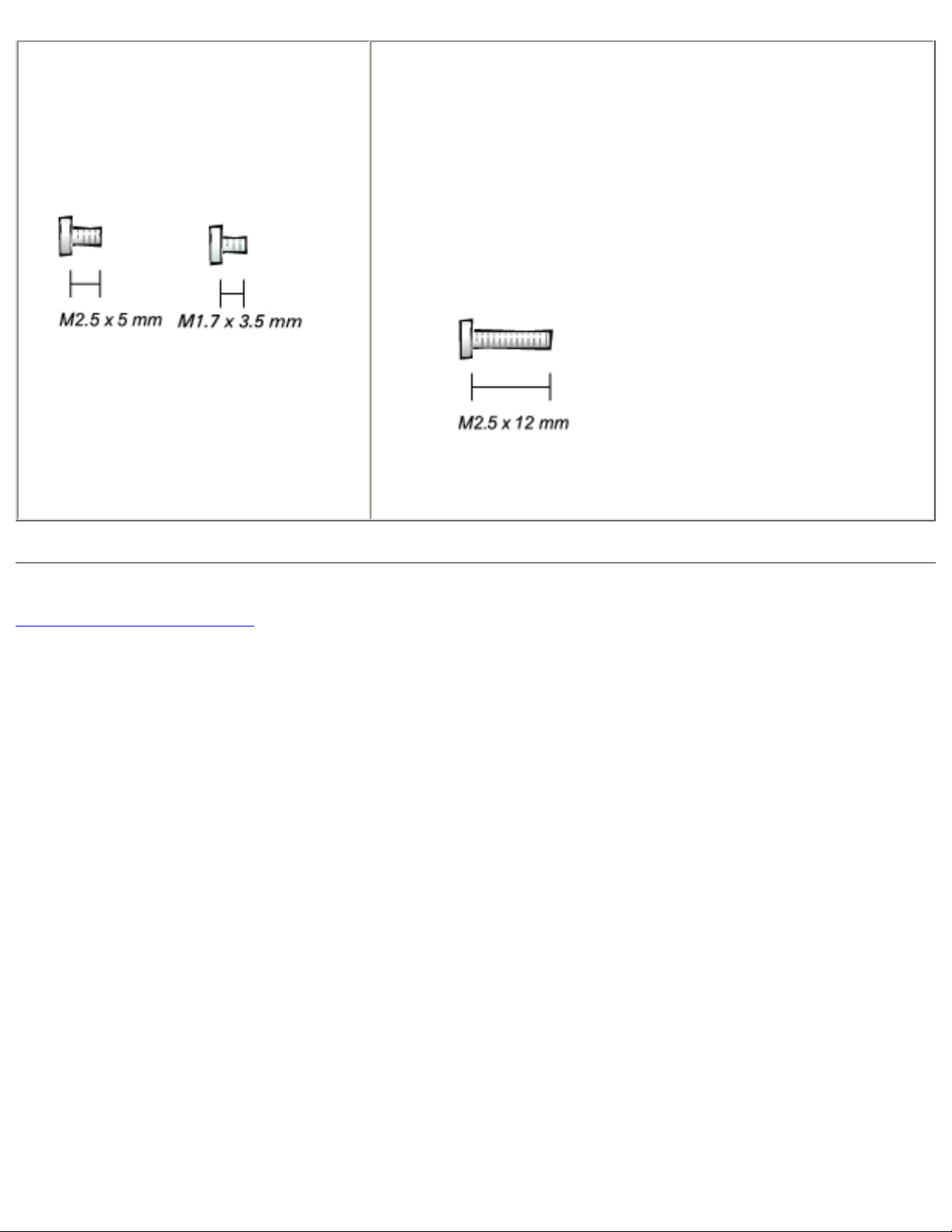
Before You Begin: Dell Latitude C610/C510 Service Manual
Display Latch:
(2 each) (2 each)
Memory Module Cover:
(2 captive screws)
(1 each)
NOTE: The single screw is one of the five keyboard
screws.
Back to Contents Page
file:///F|/Service%20Manuals/Dell/Latitude/c510-610/begin.htm (6 of 6) [2/28/2004 7:55:44 AM]

System Components: Dell Latitude C610/C510 Service Manual
Back to Contents Page
System Components
Dell™ Latitude™ C610/C510 Service Manual
Exploded View
NOTICE: Only a certified service technician should perform repairs on your
computer. Damage due to servicing that is not authorized by Dell is not covered
by your warranty.
NOTICE: Unless otherwise noted, each procedure in this manual assumes that
a part can be replaced by performing the removal procedure in reverse order.
file:///F|/Service%20Manuals/Dell/Latitude/c510-610/system.htm (1 of 3) [2/28/2004 7:55:44 AM]
System Components: Dell Latitude C610/C510 Service Manual
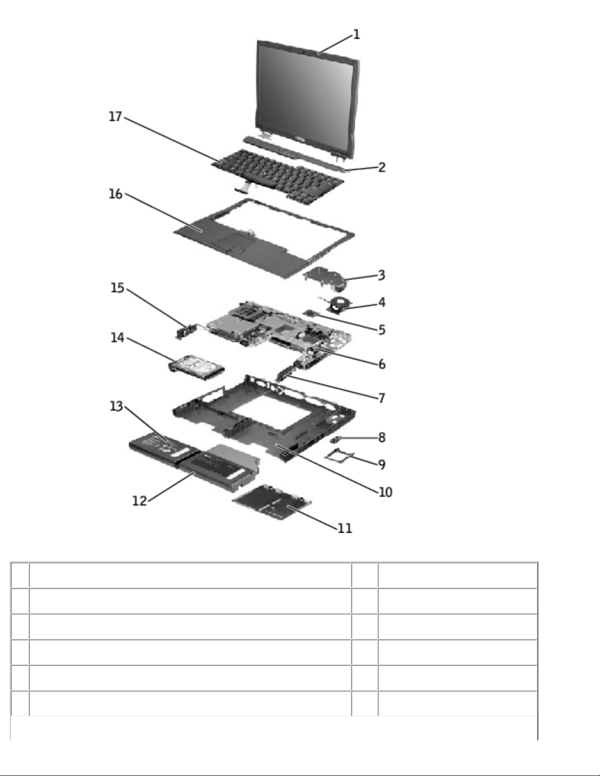
1 display assembly 10 bottom case
2 center control cover 11 memory module cover
3 microprocessor thermal cooling assembly 12 module bay device
4 hybrid cooling fan 13 main battery
5 microprocessor 14 hard drive
6 system board 15 left speaker
file:///F|/Service%20Manuals/Dell/Latitude/c510-610/system.htm (2 of 3) [2/28/2004 7:55:44 AM]

System Components: Dell Latitude C610/C510 Service Manual
7 right speaker 16 palm rest
8 modem and network-adapter connector covers 17 keyboard
9 fan guard
Back to Contents Page
file:///F|/Service%20Manuals/Dell/Latitude/c510-610/system.htm (3 of 3) [2/28/2004 7:55:44 AM]
Hard Drive: Dell Latitude C610/C510 Service Manual
Back to Contents Page
Hard Drive
Dell™ Latitude™ C610/C510 Service Manual
Removing the Hard Drive
Replacing the Hard Drive
Removing the Hard Drive
1. Save and close any open files, exit any open programs, and shut down the
computer.
NOTICE: Disconnect the computer and any attached devices from electrical
outlets, and remove any installed batteries.
NOTICE: The hard drive is very sensitive to shock. Handle the hard drive by its
edges (do not squeeze the top of the hard drive case), and avoid dropping it.
NOTICE: Read "Preparing to Work Inside the Computer" before performing the
following procedure.
NOTICE: To prevent data loss, turn off your computer before removing the
hard drive. Do not remove the hard drive while the computer is running, in
standby mode, or in hibernate mode.
CAUTION: If you remove the hard drive from the computer when the
drive is hot, do not touch the metal housing of the hard drive.
2. Ground yourself by touching a metal connector on the back of the computer.
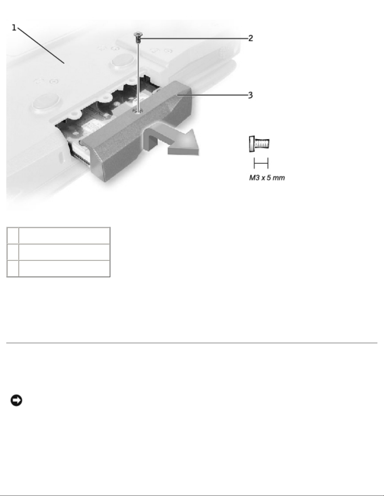
3. Turn the computer over. Remove the M3 x 5-mm screw from the hard drive
door.
Hard Drive Removal
file:///F|/Service%20Manuals/Dell/Latitude/c510-610/hdd.htm (1 of 3) [2/28/2004 7:55:45 AM]
Hard Drive: Dell Latitude C610/C510 Service Manual
1 bottom of computer
2 M3 x 5-mm screw
3 hard drive door
4. Lift up the hard drive door until you hear a click.
5. Slide the hard drive out of the computer.
Replacing the Hard Drive
NOTICE: Use firm and even pressure to slide the hard drive into place. If you
force the hard drive into place using excessive force, you may damage the
connector.
1. Lift up the hard drive door until you hear a click. Push the hard drive into the
drive bay until it is fully seated in the bay.
file:///F|/Service%20Manuals/Dell/Latitude/c510-610/hdd.htm (2 of 3) [2/28/2004 7:55:45 AM]

Hard Drive: Dell Latitude C610/C510 Service Manual
2. Press the hard drive door down.
3. Replace the M3 x 5-mm screw in the hard drive door.
Back to Contents Page
file:///F|/Service%20Manuals/Dell/Latitude/c510-610/hdd.htm (3 of 3) [2/28/2004 7:55:45 AM]

Memory Modules, Mini PCI Card, and Modem: Dell Latitude C610/C510 Service Manual
Back to Contents Page
Memory Modules, Mini PCI Card, and
Modem
Dell™ Latitude™ C610/C510 Service Manual
Memory Modules
Mini PCI Card
Modem
Memory Modules
Removing the Memory Module Cover
NOTICE: Disconnect the computer and any attached devices from electrical
outlets, and remove any installed batteries.
NOTICE: To avoid ESD, ground yourself by using a wrist grounding strap or by
touching an unpainted metal surface on the computer.
NOTICE: Read "Preparing to Work Inside the Computer" before performing the
following procedure.
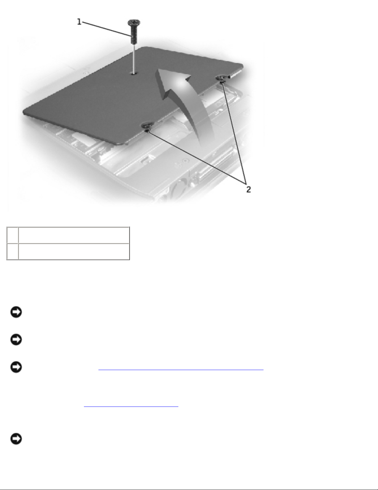
1. Turn the computer over, and use a flat-blade screwdriver to release the two
captive screws from the memory module cover.
2. Remove the M2.5 x 12-mm screw labeled "circle K." (The screw is one of the
five keyboard screws.)
3. Place your finger under the cover at the indentation and lift and slide the cover
open.
Memory Module Cover
file:///F|/Service%20Manuals/Dell/Latitude/c510-610/upgrades.htm (1 of 8) [2/28/2004 7:55:46 AM]
Memory Modules, Mini PCI Card, and Modem: Dell Latitude C610/C510 Service Manual
1 M2.5 x 12-mm screw (1)
2 captive screws (2)
Removing the Memory Modules
NOTICE: Disconnect the computer and any attached devices from electrical
outlets, and remove any installed batteries.
NOTICE: To avoid ESD, ground yourself by using a wrist grounding strap or by
touching an unpainted metal surface on the computer.
NOTICE: Read "Preparing to Work Inside the Computer" before performing the
following procedure.
1. Remove the
memory module cover.
NOTICE: To prevent damage to the memory module connector, do not use
tools to spread the inner metal tabs that secure the memory module.
file:///F|/Service%20Manuals/Dell/Latitude/c510-610/upgrades.htm (2 of 8) [2/28/2004 7:55:46 AM]
Memory Modules, Mini PCI Card, and Modem: Dell Latitude C610/C510 Service Manual
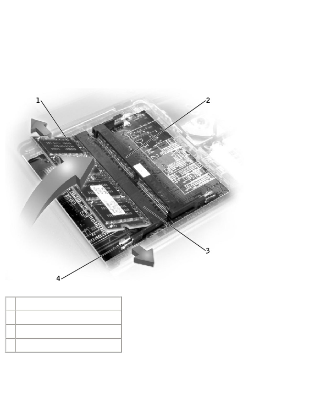
2. Use your fingertips to carefully spread apart the inner tabs on each end of the
memory module socket.
The module should pop up.
Memory Module Removal
1 JDIM 1
2 JDIM 2
3 memory module sockets (2)
4 inner tabs (2 per socket)
3. Lift the memory module out of its socket.
file:///F|/Service%20Manuals/Dell/Latitude/c510-610/upgrades.htm (3 of 8) [2/28/2004 7:55:46 AM]

Memory Modules, Mini PCI Card, and Modem: Dell Latitude C610/C510 Service Manual
Replacing the Memory Modules
1. If you only have one memory module, install it in the connector labeled "JDIM1"
on the system board. Install a second memory module in the connector labeled
"JDIM2."
NOTE: Memory modules are keyed, or designed to fit into their sockets, in only
one direction.
NOTICE: The memory module must be inserted at a 45-degree angle to avoid
damaging the connector.
2. Align the notch in the memory module with the slot in the center of the socket.
3. Slide the edge connector of the module firmly into the socket at a
45-degree angle, and rotate the module down until you hear a click. If you do
not hear the click, remove the module and reinstall it.
4. Replace the cover and tighten the two captive screws.
Mini PCI Card
You must remove the Mini PCI card before the system board can be removed.
Removing the Mini PCI Card
NOTICE: Disconnect the computer and any attached devices from electrical
outlets, and remove any installed batteries.
NOTICE: To avoid ESD, ground yourself by using a wrist grounding strap or by
touching an unpainted metal surface on the computer.
NOTICE: Read "Preparing to Work Inside the Computer" before performing the
following procedure.
1. Remove the
memory module cover.
file:///F|/Service%20Manuals/Dell/Latitude/c510-610/upgrades.htm (4 of 8) [2/28/2004 7:55:46 AM]
Memory Modules, Mini PCI Card, and Modem: Dell Latitude C610/C510 Service Manual
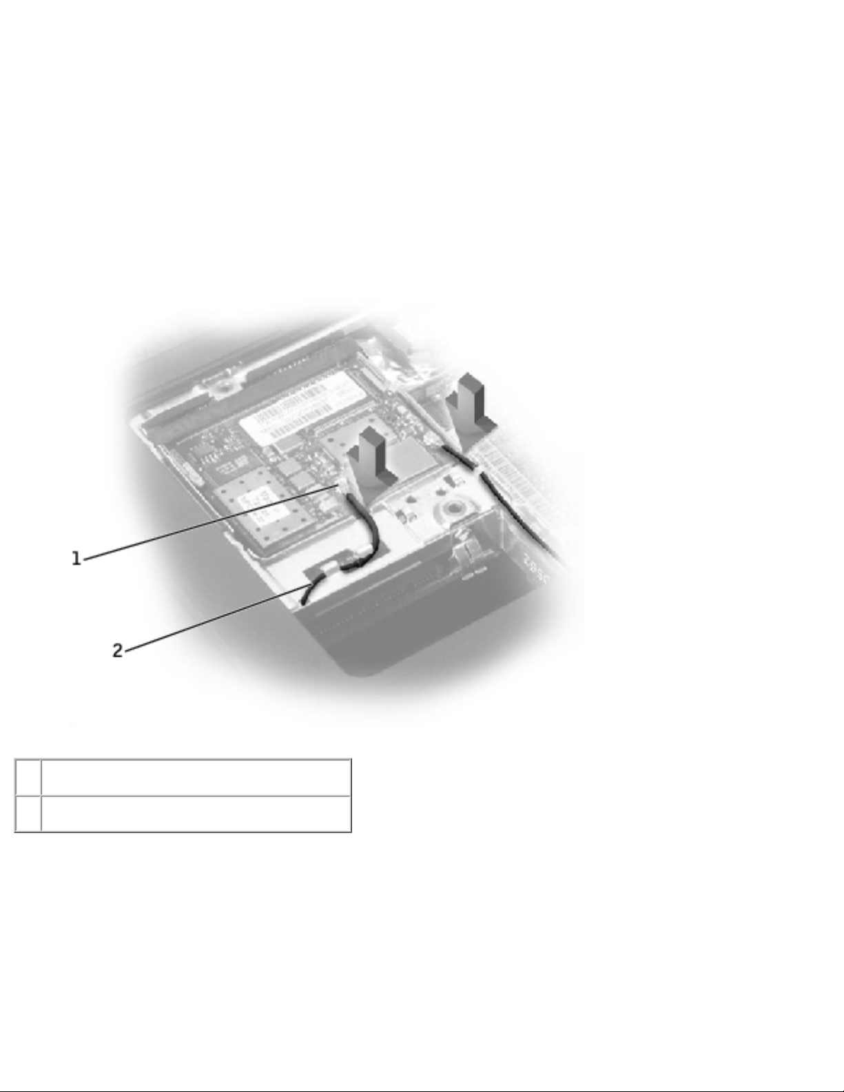
2. Disconnect the Mini PCI card from the antenna cables.
3. To release a Mini PCI card from its socket, spread apart the metal securing tabs
until the card pops up slightly.
4. Lift the Mini PCI card out of its connector.
Mini PCI Card
1 antenna connectors on card (2)
2 antenna cables (2)
Replacing the Mini PCI Card
1. Align the Mini PCI card with the socket at a 45-degree angle, and press the Mini
PCI card into the socket.
file:///F|/Service%20Manuals/Dell/Latitude/c510-610/upgrades.htm (5 of 8) [2/28/2004 7:55:46 AM]

Memory Modules, Mini PCI Card, and Modem: Dell Latitude C610/C510 Service Manual
NOTICE: The connectors are keyed for correct insertion; do not force the
connections.
2. Lower the Mini PCI card toward the inner tabs to approximately a
20-degree angle.
3. Continue lowering the Mini PCI card until it snaps into the inner tabs of the
socket.
4. Attach the antenna cables to the Mini PCI card.
5. Replace the cover and tighten the two captive screws.
Modem
Removing the Modem
NOTICE: Disconnect the computer and any attached devices from electrical
outlets, and remove any installed batteries.
NOTICE: To avoid ESD, ground yourself by using a wrist grounding strap or by
touching an unpainted metal surface on the computer.
NOTICE: Read "Preparing to Work Inside the Computer" before performing the
following procedure.
1. Turn the computer over, and remove the
memory module cover.
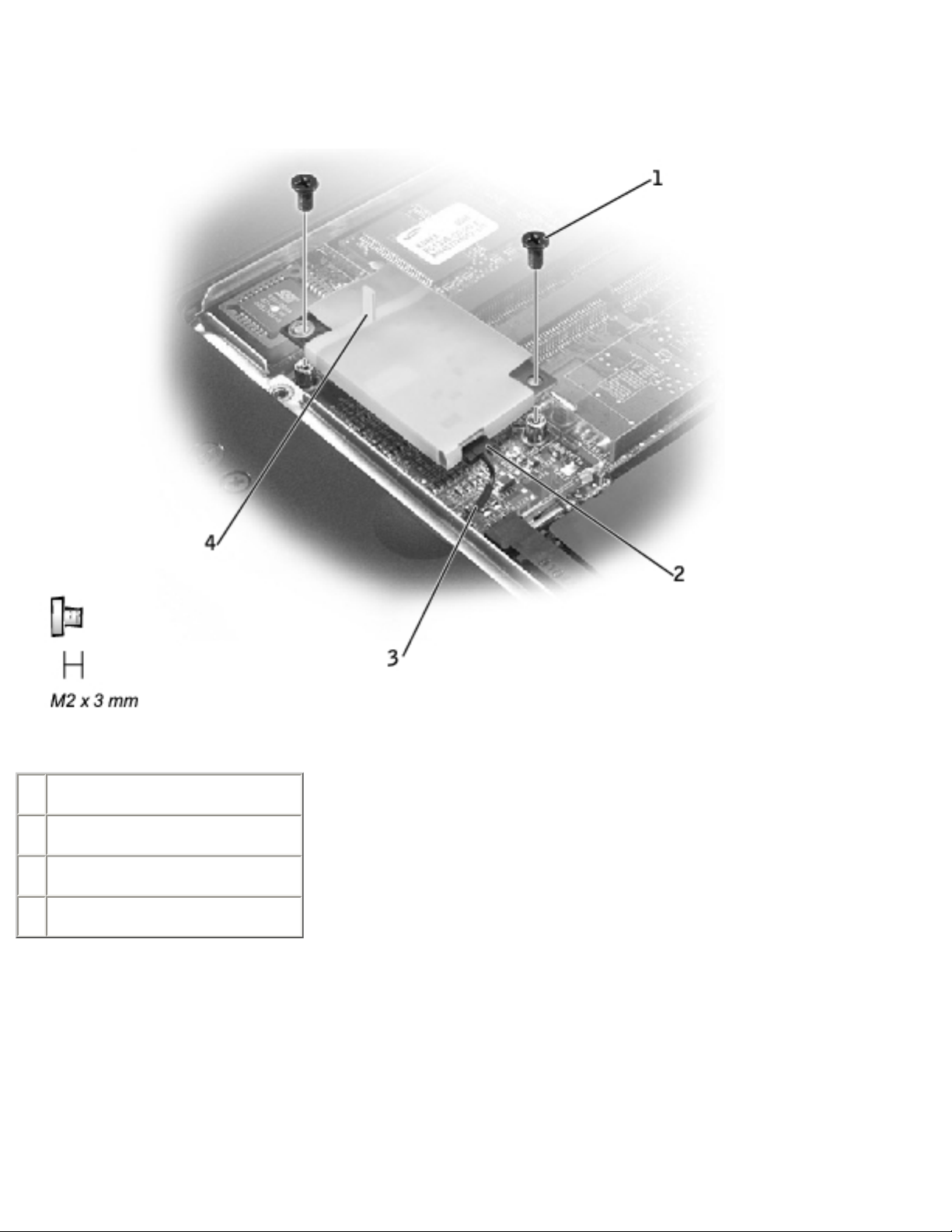
2. Remove the two M2 x 3-mm screws that secure the modem to the system
board.
NOTICE: Do not pull on the modem cable. Pull from the modem connector to
disconnect the cable.
3. Pull straight up on the attached pull tab to lift the modem out of its connector on
the system board and disconnect the modem cable.
file:///F|/Service%20Manuals/Dell/Latitude/c510-610/upgrades.htm (6 of 8) [2/28/2004 7:55:46 AM]
Memory Modules, Mini PCI Card, and Modem: Dell Latitude C610/C510 Service Manual
Modem Removal
1 M2 x 3-mm screws (2)
2 modem connector
3 modem cable
4 pull tab
Replacing the Modem
1. Connect the modem cable to the modem.
file:///F|/Service%20Manuals/Dell/Latitude/c510-610/upgrades.htm (7 of 8) [2/28/2004 7:55:46 AM]

Memory Modules, Mini PCI Card, and Modem: Dell Latitude C610/C510 Service Manual
NOTICE: The connectors are keyed for correct insertion; do not force the
connections.
2. Align the modem with the screw holes and press the modem into the connector
on the system board.
3. Install the two M2 x 3-mm screws that secure the modem to the system board.
4. Replace the
memory module cover and tighten the two captive screws.
Back to Contents Page
file:///F|/Service%20Manuals/Dell/Latitude/c510-610/upgrades.htm (8 of 8) [2/28/2004 7:55:46 AM]

Keyboard: Dell Latitude C610/C510 Service Manual
Back to Contents Page
Keyboard
Dell™ Latitude™ C610/C510 Service Manual
Removing the Keyboard
Replacing the Keyboard
Removing the Keyboard
NOTICE: Disconnect the computer and any attached devices from electrical
outlets, and remove any installed batteries.
NOTICE: To avoid ESD, ground yourself by using a wrist grounding strap or by
touching an unpainted metal surface on the computer.
NOTICE: Read "Preparing to Work Inside the Computer" before performing the
following procedure.
1. Remove the
hard drive.
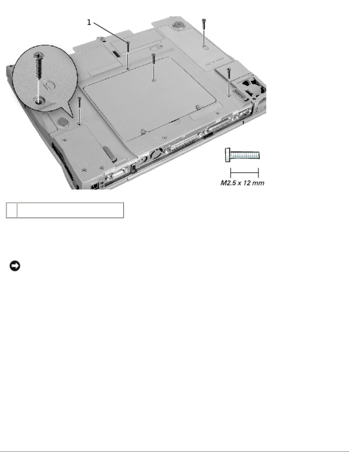
2. Turn the computer over, and remove the five M2.5 x 12-mm screws labeled
"circle K."
Screw Removal
file:///F|/Service%20Manuals/Dell/Latitude/c510-610/keyboard.htm (1 of 6) [2/28/2004 7:55:47 AM]
Keyboard: Dell Latitude C610/C510 Service Manual
1 M2.5 x 12-mm screws (5)
3. Turn the computer over and open the display.
NOTICE: The key caps on the keyboard are fragile, easily dislodged, and time-
consuming to replace. Be careful when removing and handling the keyboard.
4. Remove the center control cover.
a. Use a small, flat-blade screwdriver or plastic scribe to lift the right edge of
the center control cover and pry it loose from the bottom case.
b. Lift the center control cover up and away from the bottom case.
Center Control Cover Removal
file:///F|/Service%20Manuals/Dell/Latitude/c510-610/keyboard.htm (2 of 6) [2/28/2004 7:55:47 AM]
Keyboard: Dell Latitude C610/C510 Service Manual
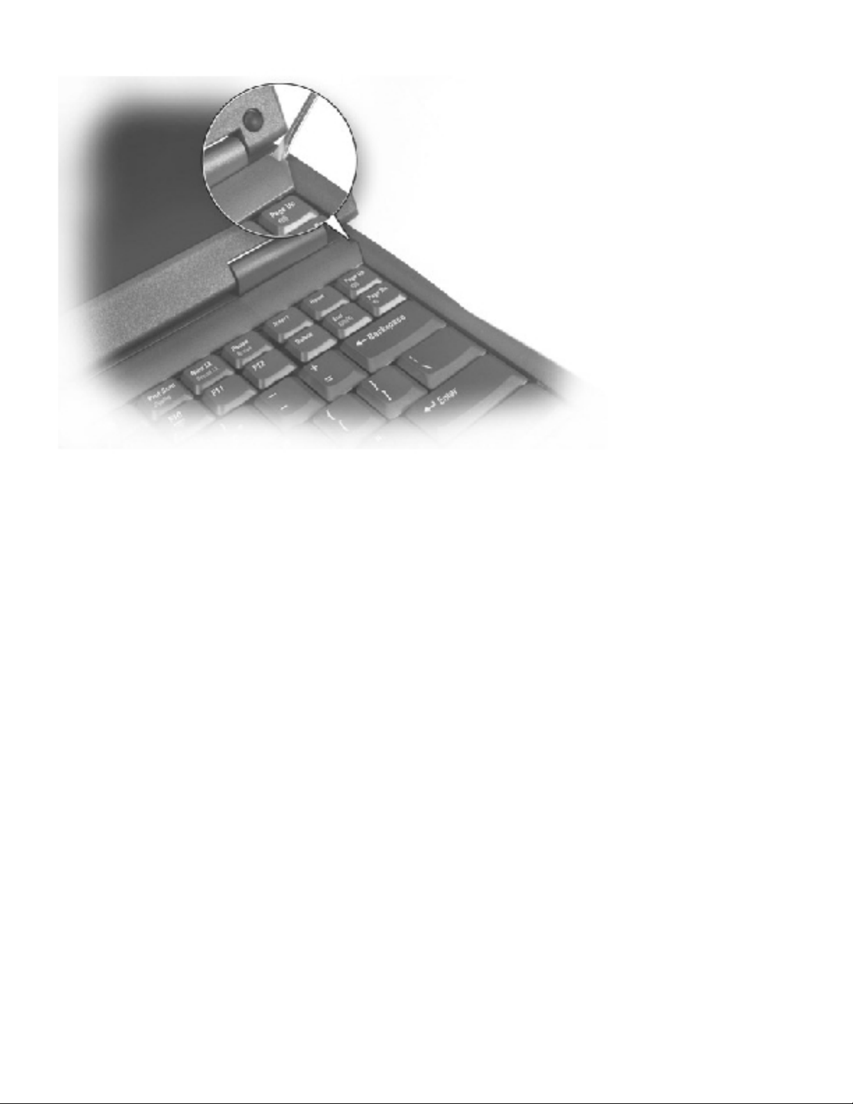
5. To release the keyboard from the palm rest, use a small, flat-blade screwdriver
or plastic scribe to pull up on the scalloped edge of the blank key on the
keyboard.
Keyboard Removal
file:///F|/Service%20Manuals/Dell/Latitude/c510-610/keyboard.htm (3 of 6) [2/28/2004 7:55:47 AM]
 Loading...