

DELL Latitude C400 Service Manual

Please check out our eBay auctions for more great
deals on Factory Service Manuals:
Dell Latitude C400 Service Manual
Dell™ Latitude™ C400 Service Manual
Before You Begin
System Components
Keyboard
Memory Module and Modem Daughter Card
Hard Drive
Wireless Network Adapter
Display Assembly and Display Latch
Palm Rest
Cooling Fan
Reserve Battery
Flashing the BIOS
Audio Board
System Board
Battery Latch
Pin Assignments for I/O Connectors
Notes, Notices, and Cautions
NOTE: A NOTE indicates important information that helps you make better use of your
computer.
NOTICE: A NOTICE indicates either potential damage to hardware or loss of data and tells you
how to avoid the problem.
CAUTION: A CAUTION indicates a potential for property damage, personal injury, or
death.
Information in this document is subject to change without notice.
© 2001 Dell Computer Corporation. All rights reserved.
Reproduction in any manner whatsoever without the written permission of Dell Computer Corporation is strictly forbidden.
Trademarks used in this text: Dell, the DELL logo, and Latitude are trademarks of Dell Computer Corporation; Intel is a
registered trademark of Intel Corporation; Microsoft and Windows are registered trademarks of Microsoft Corporation.
Other trademarks and trade names may be used in this document to refer to either the entities claiming the marks and
names or their products. Dell Computer Corporation disclaims any proprietary interest in trademarks and trade names other
than its own.
file:///I|/SERVICE%20MANUALS/DELL%20MANUALS/LA...ok/Latitude/C400/C400_SERVICE_MANUAL/index.htm (1 of 2)6/21/2004 1:20:07 AM

Dell Latitude C400 Service Manual
October 2001 Rev. A00
file:///I|/SERVICE%20MANUALS/DELL%20MANUALS/LA...ok/Latitude/C400/C400_SERVICE_MANUAL/index.htm (2 of 2)6/21/2004 1:20:07 AM

Before You Begin : Dell Latitude C400 Service Manual
Back to Contents Page
Before You Begin
Dell™ Latitude™ C400 Service Manual
Preparing to Work Inside the Computer
Recommended Tools
Screw Identification
Preparing to Work Inside the Computer
NOTICE: Only a certified service technician should perform repairs on your computer. Damage
due to servicing that is not authorized by Dell is not covered by your warranty.
NOTICE: To avoid damaging the computer, perform the following steps before you begin
working inside the computer.
1. Make sure that the work surface is clean to prevent scratching the computer cover.
2. Save any work in progress and close all open application programs.
3. Turn off the computer and all attached devices.
NOTE: Make sure the computer is turned off and not in suspend-to-disk or hibernate mode. If
you cannot shut down the computer using the computer's operating system, press and hold the
power button for 4 seconds.
4. Make sure the computer is undocked.
5. Disconnect the computer from the electrical outlet.
6. To avoid possible damage to the system board, wait 10 to 20 seconds and then disconnect any
attached devices.
7. Disconnect all other external cables from the computer, including the IDE modular bay cable (if
connected).
8. Remove any installed PC Cards or plastic blanks from the PC Card slot.
9. Close the display and turn the computer upside down on a flat work surface.
file:///I|/SERVICE%20MANUALS/DELL%20MANUALS/LA...ok/Latitude/C400/C400_SERVICE_MANUAL/begin.htm (1 of 6)6/21/2004 1:20:09 AM

Before You Begin : Dell Latitude C400 Service Manual
NOTICE: To avoid damaging the system board, you must remove the battery before you
service the computer.
10. Remove the battery from the battery bay.
11. To dissipate any static electricity while you work, use a wrist grounding strap or periodically
touch an unpainted metal surface.
12. Handle components and cards with care. Do not touch the components or contacts on a card.
Hold a card by it edges or by its metal mounting bracket. Hold internal components by their
edges, not by their pins.
Recommended Tools
The procedures in this manual require the following tools:
● #1 magnetized Phillips screwdriver
● Small flat-blade screwdriver
● 5-mm nut driver
● 7-mm nut driver
● Needle-nose pliers
● Flash BIOS update program floppy disk or CD
Computer Orientation
file:///I|/SERVICE%20MANUALS/DELL%20MANUALS/LA...ok/Latitude/C400/C400_SERVICE_MANUAL/begin.htm (2 of 6)6/21/2004 1:20:09 AM
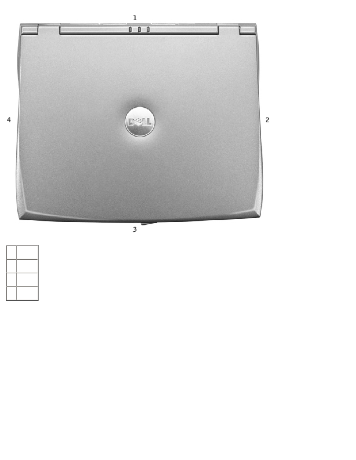
Before You Begin : Dell Latitude C400 Service Manual
1 back
2 right
3 front
4 left
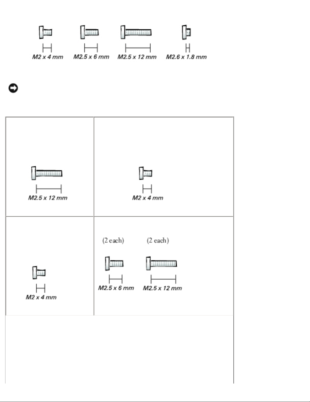
Screw Identification
When you are removing and replacing components, photocopy the placemat as a tool to lay out and
keep track of the screws. The placemat provides the number of screws and their sizes.
Screw Identification
file:///I|/SERVICE%20MANUALS/DELL%20MANUALS/LA...ok/Latitude/C400/C400_SERVICE_MANUAL/begin.htm (3 of 6)6/21/2004 1:20:09 AM
Before You Begin : Dell Latitude C400 Service Manual
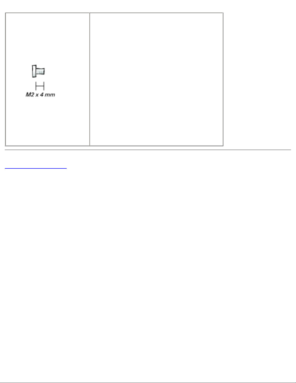
NOTICE: When reinstalling a screw, you must use a screw of the correct diameter and length.
Make sure that the screw is properly aligned with its corresponding hole, and avoid
overtightening.
Hard Drive Door:
(1 each)
Modem Daughter Card:
(1 each)
Keyboard:
(4 each)
Display Assembly:
file:///I|/SERVICE%20MANUALS/DELL%20MANUALS/LA...ok/Latitude/C400/C400_SERVICE_MANUAL/begin.htm (4 of 6)6/21/2004 1:20:09 AM
Before You Begin : Dell Latitude C400 Service Manual
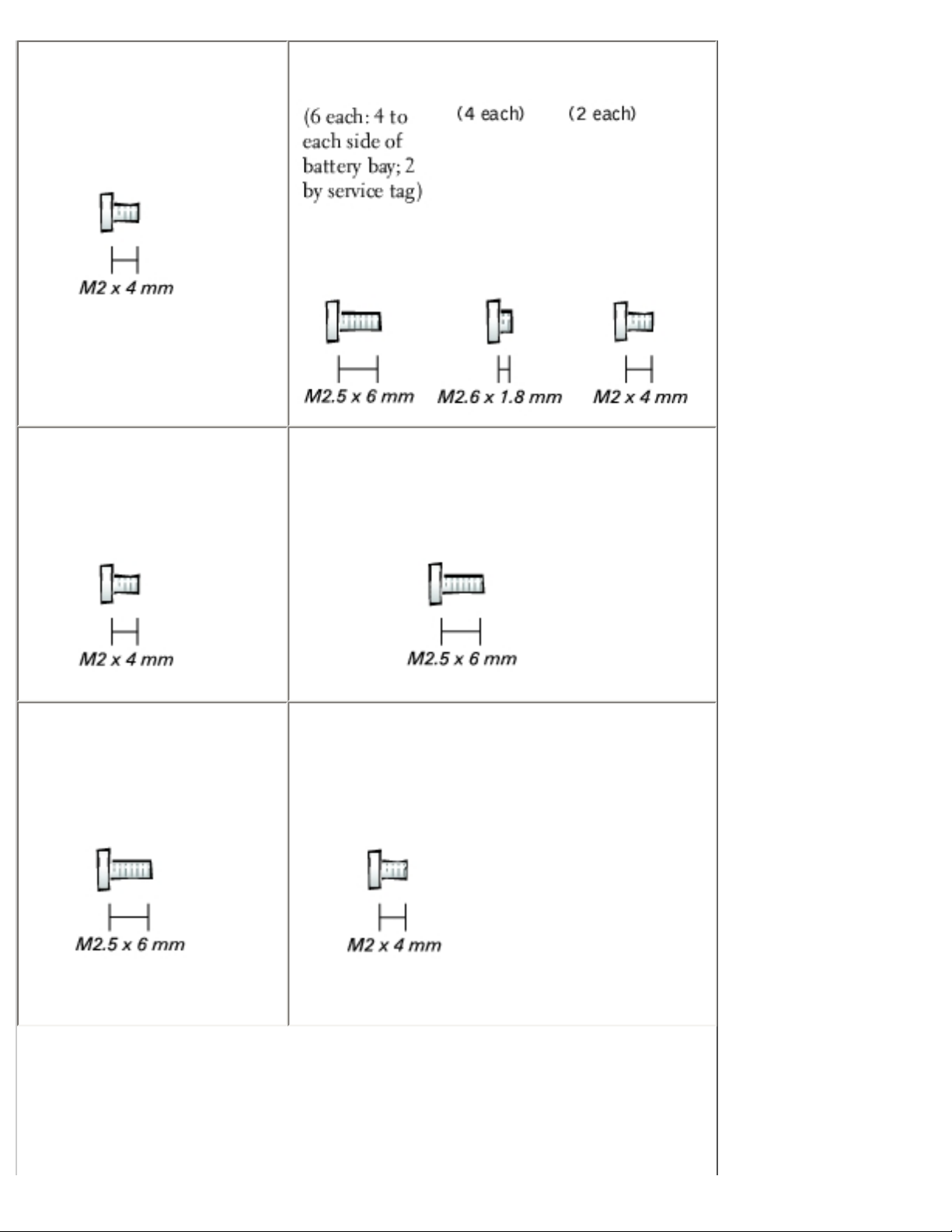
Display Bezel:
(6 each)
Rubber screw covers: 6 each
Palm Rest to Bottom Case:
Critical Component Shield:
(6 each)
Palm Rest to System Board:
(6 each)
Cooling Fan:
(3 each)
Audio Board:
(2 each)
file:///I|/SERVICE%20MANUALS/DELL%20MANUALS/LA...ok/Latitude/C400/C400_SERVICE_MANUAL/begin.htm (5 of 6)6/21/2004 1:20:09 AM
Before You Begin : Dell Latitude C400 Service Manual
System Board:
(1 each)
Guide pins: 2 each
5-mm hex nuts: 4 each
7-mm hex nuts: 2 each
Back to Contents Page
file:///I|/SERVICE%20MANUALS/DELL%20MANUALS/LA...ok/Latitude/C400/C400_SERVICE_MANUAL/begin.htm (6 of 6)6/21/2004 1:20:09 AM
System Components : Dell Latitude C400 Service Manual
Back to Contents Page
System Components
Dell™ Latitude™ C400 Service Manual
NOTICE: Only a certified service technician should perform repairs on your computer. Damage
due to servicing that is not authorized by Dell is not covered by your warranty.
NOTICE: Unless otherwise noted, each procedure in this manual assumes that a part can be
replaced by performing the removal procedure in reverse order.
System Components
file:///I|/SERVICE%20MANUALS/DELL%20MANUALS/LA...k/Latitude/C400/C400_SERVICE_MANUAL/system.htm (1 of 2)6/21/2004 1:20:09 AM
System Components : Dell Latitude C400 Service Manual
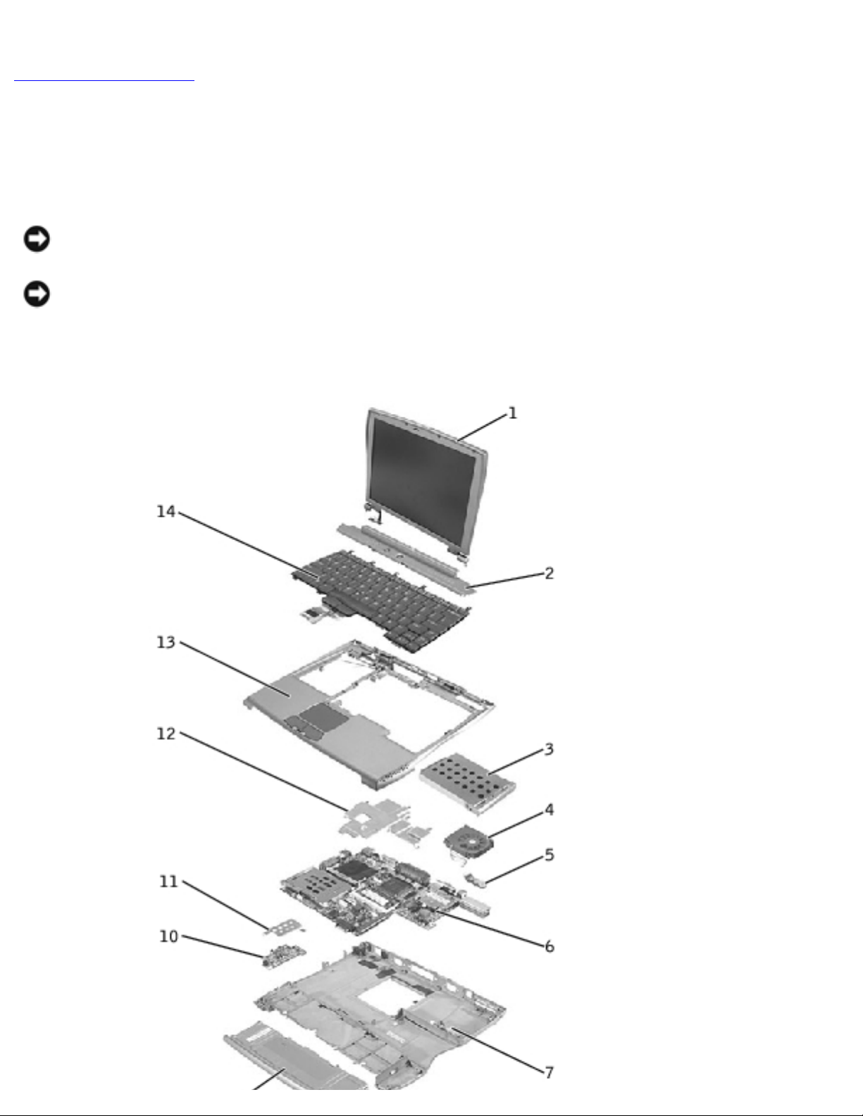
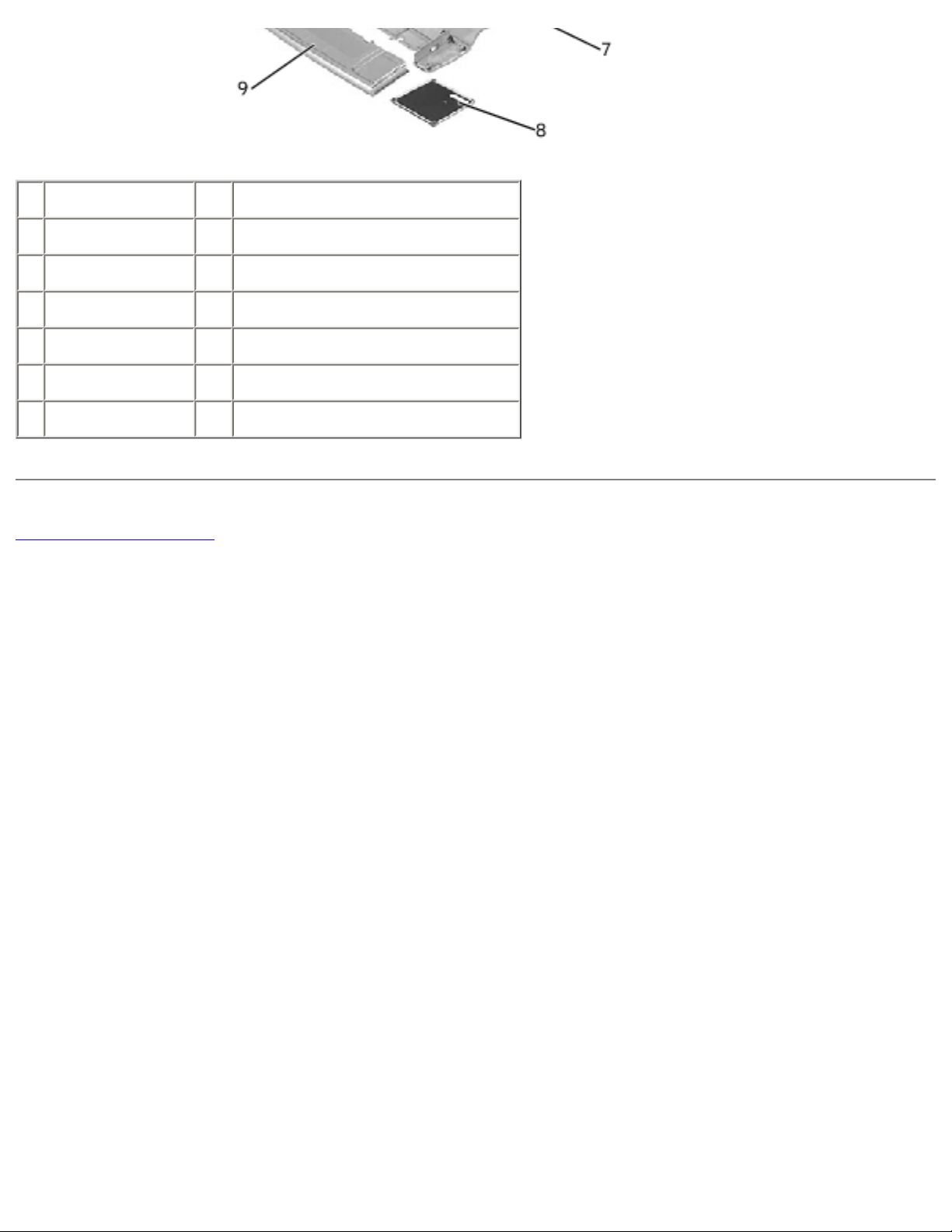
1 display 8 memory module/modem cover
2 center cover 9 battery
3 hard drive 10 audio card
4 cooling fan 11 audio card shield
5 reserve battery 12 critical component shield
6 system board 13 palm rest
7 bottom case 14 keyboard
Back to Contents Page
file:///I|/SERVICE%20MANUALS/DELL%20MANUALS/LA...k/Latitude/C400/C400_SERVICE_MANUAL/system.htm (2 of 2)6/21/2004 1:20:09 AM

Keyboard : Dell Latitude C400 Service Manual
Back to Contents Page
Keyboard
Dell™ Latitude™ C400 Service Manual
Removing the Keyboard
Replacing the Keyboard
Removing the Keyboard
NOTICE: Disconnect the computer and any attached devices from electrical outlets, and
remove any installed batteries.
NOTICE: To avoid ESD, ground yourself by using a wrist grounding strap or by touching an
unpainted metal surface on the computer.
NOTICE: Read "Preparing to Work Inside the Computer" before performing the following
procedure.
1. Remove the hard drive.
NOTICE: The key caps on the keyboard are fragile, easily dislodged, and time-consuming to
replace. Be careful when removing and handling the keyboard.
2. Turn the computer right-side up and remove the center cover.
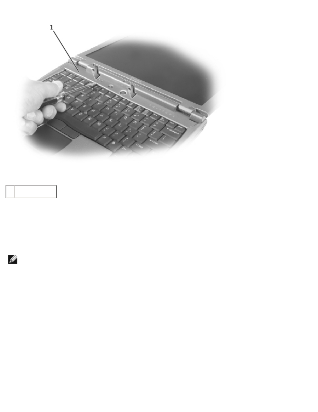
Center Cover Removal
file:///I|/SERVICE%20MANUALS/DELL%20MANUALS/LA...Latitude/C400/C400_SERVICE_MANUAL/keyboard.htm (1 of 6)6/21/2004 1:20:10 AM
Keyboard : Dell Latitude C400 Service Manual
1 center cover
a. Open the computer all the way (180 degrees) so that it lies flat against your work
surface.
b. Press and hold down the <F4> and <F5> keys to reveal the left release slot of the
center cover.
NOTE: To protect the keycaps, it may be helpful to place a straightedge (such as a short ruler)
across the first row or two of keycaps, and press on the straightedge instead of on the keycaps
themselves.
c. Insert a flat-blade screwdriver into the slot. While holding the screwdriver, make your
hand into a fist, brace your knuckles against the keyboard, and pry up the center cover.
d. Repeat steps b and c for the right release slot, located behind the <F9> and <F10>
keys.
e. Lift the center cover up and away from the bottom case.
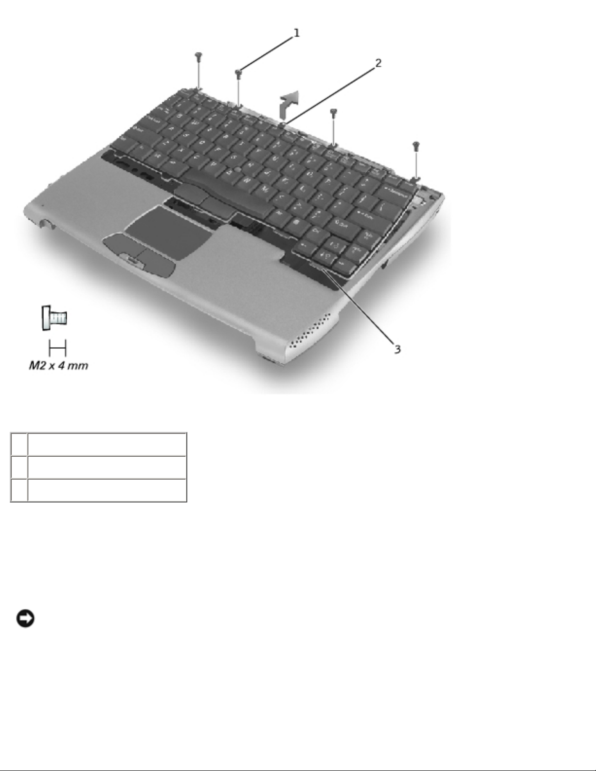
3. Remove the four M2 x 4-mm screws that secure the back edge of the keyboard.
Keyboard Screws
file:///I|/SERVICE%20MANUALS/DELL%20MANUALS/LA...Latitude/C400/C400_SERVICE_MANUAL/keyboard.htm (2 of 6)6/21/2004 1:20:10 AM
Keyboard : Dell Latitude C400 Service Manual
1 M2 x 4-mm screws (4)
2 keyboard locator tab
3 keyboard securing tabs (5)
4. Pry up the keyboard locator tab, lift the back edge of the keyboard slightly, and then pull the
keyboard a small distance toward the back of the computer to release the five securing tabs
located across the front edge of the keyboard.
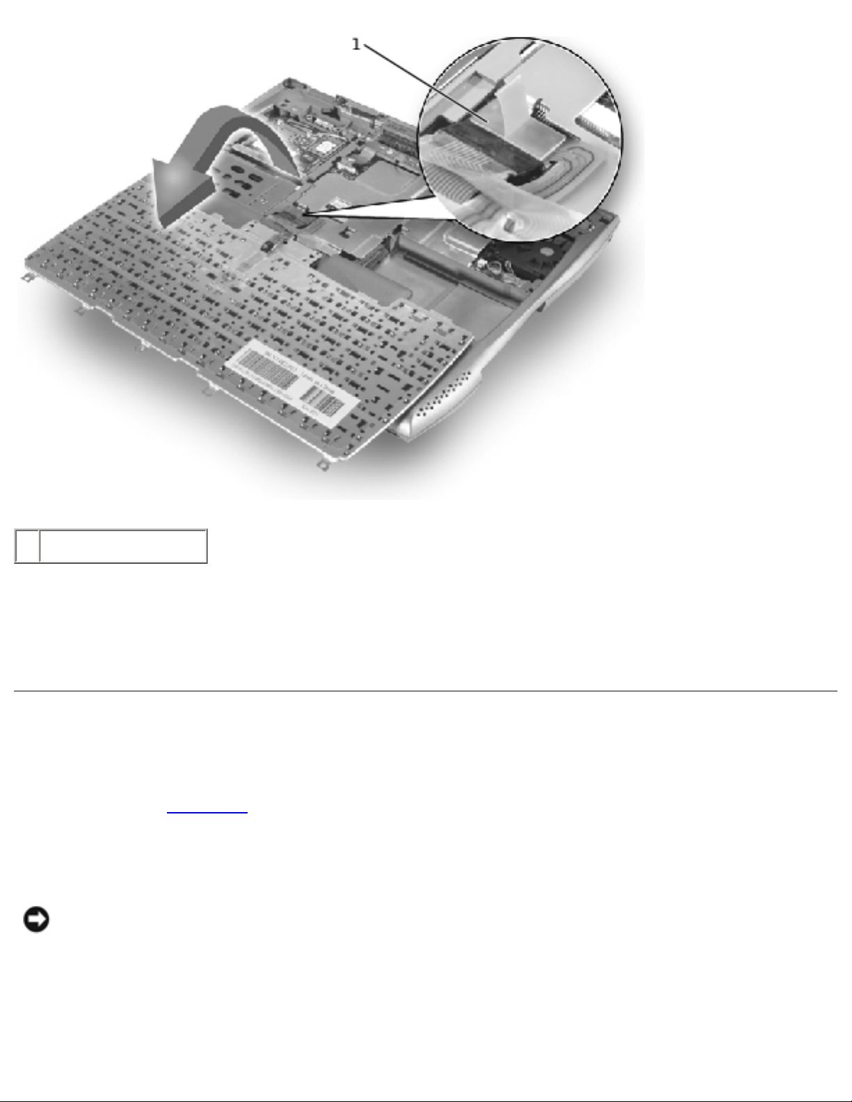
5. Rotate the keyboard toward the front of the computer and place it face-down on the palm rest.
NOTICE: Do not pull on the keyboard flex
cable.
Keyboard Removal
file:///I|/SERVICE%20MANUALS/DELL%20MANUALS/LA...Latitude/C400/C400_SERVICE_MANUAL/keyboard.htm (3 of 6)6/21/2004 1:20:10 AM
Keyboard : Dell Latitude C400 Service Manual
1 keyboard flex cable
6. Use the pull tab to pull the keyboard flex cable up from its connector on the system board.
The keyboard is now disconnected from the bottom case.
Replacing the Keyboard
1. Replace the hard drive.
2. Place the keyboard face-down on the palm rest, with the keyboard flex cable pointing toward
the back of the computer.
NOTICE: To avoid damage to the connector pins, press the keyboard flex cable connector
evenly into the interface connector on the system board, and do not reverse the keyboard
connector.
3. Connect the keyboard flex cable to its interface connector on the system board.
file:///I|/SERVICE%20MANUALS/DELL%20MANUALS/LA...Latitude/C400/C400_SERVICE_MANUAL/keyboard.htm (4 of 6)6/21/2004 1:20:10 AM
Keyboard : Dell Latitude C400 Service Manual
To aid with proper flex cable connection, a white locator line has been added near the end of the
flex cable. Press the cable into the connector until the white line disappears and hold it steady
while you snap the flex cable connector down. (The white line may reappear after the connector is
closed; this should not indicate a problem with the connection.)
NOTICE: Position the keyboard flex cable so that it is not pinched when you replace the
keyboard in the bottom case.
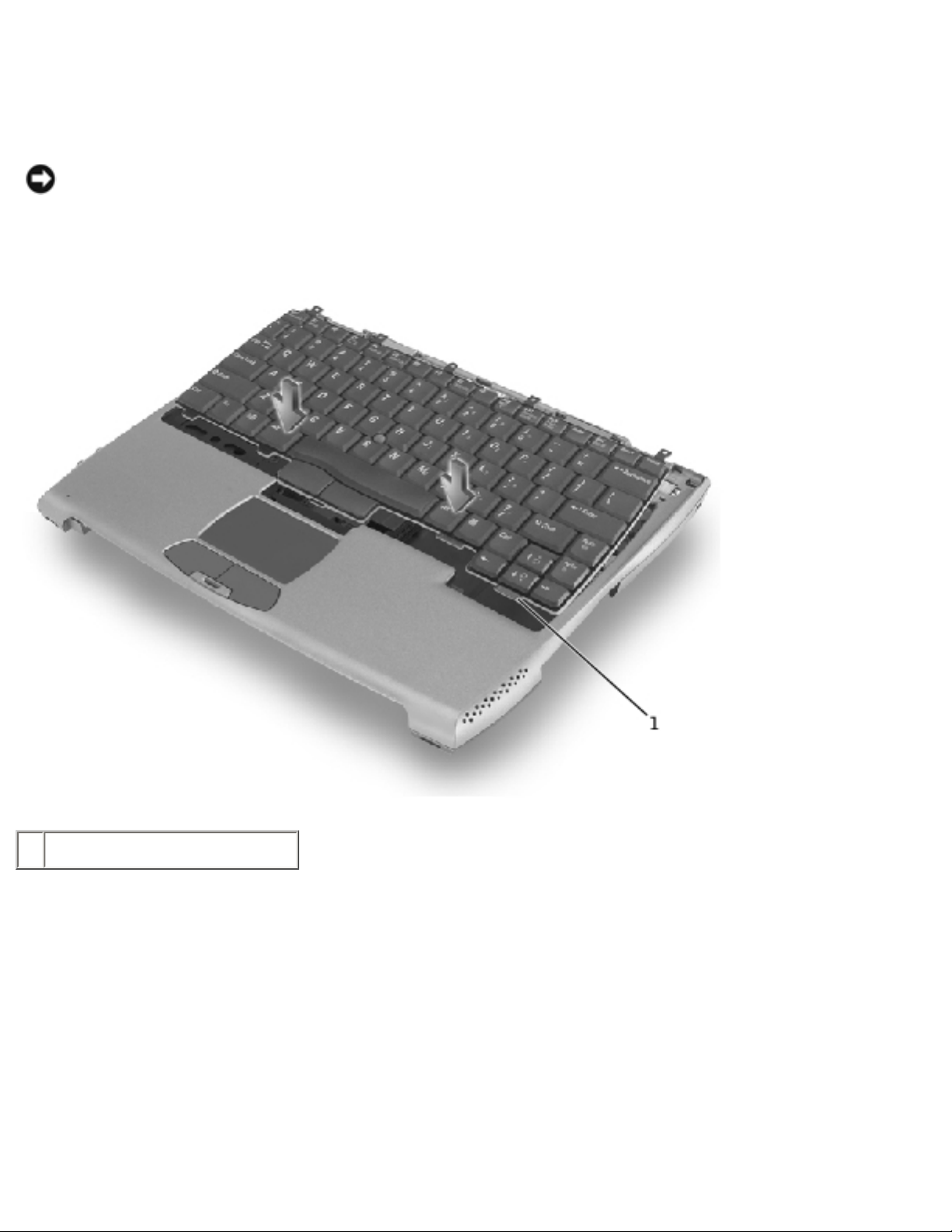
Keyboard Replacement
1 keyboard securing tabs (5)
4. Carefully rotate the keyboard back and fit it into the bottom case.
Ensure that all five securing tabs are engaged in their respective slots before trying to completely
seat the keyboard. Fitting the tabs to the slots may be easiest when viewed from above and
slightly behind the front edge of the keyboard. Press down on the left and right <ALT> keys to
help control tab/slot alignment.
When the keyboard appears to be completely seated, confirm that the front edge of the keyboard
is aligned with the edge of the palm rest before proceeding.
5. Replace the four M2 x 4-mm screws at the back of the keyboard.
file:///I|/SERVICE%20MANUALS/DELL%20MANUALS/LA...Latitude/C400/C400_SERVICE_MANUAL/keyboard.htm (5 of 6)6/21/2004 1:20:10 AM

Keyboard : Dell Latitude C400 Service Manual
6. Replace the center cover.
Back to Contents Page
file:///I|/SERVICE%20MANUALS/DELL%20MANUALS/LA...Latitude/C400/C400_SERVICE_MANUAL/keyboard.htm (6 of 6)6/21/2004 1:20:10 AM
Memory Module and Modem Daughter Card : Dell Latitude C400 Service Manual
Back to Contents Page
Memory Module and Modem Daughter Card
Dell™ Latitude™ C400 Service Manual
Removing the Memory Module/Modem Cover
Removing the Memory Modules
Replacing the Memory Modules
Removing the Modem Daughter Card
Replacing the Modem Daughter Card
Removing the Memory Module/Modem Cover
NOTE: This procedure covers removing and replacing the memory module located under the
memory module/modem cover on the bottom of the computer. A second memory module
resides on the upper surface of the system board under the critical component shield. To
replace the memory module under the critical component shield, perform the procedure for
removing the palm rest up to and including removal of the critical component shield. Then
replace the memory module.
NOTICE: Disconnect the computer and any attached devices from electrical outlets, and
remove any installed batteries.
NOTICE: To avoid ESD, ground yourself by using a wrist grounding strap or by touching an
unpainted metal surface on the computer.
NOTICE: Read "Preparing to Work Inside the Computer" before performing the following
procedure.
1. Turn the computer over, and use a #1 Phillips screwdriver to release the two captive screws
from the memory module/modem cover.
2. Place your finger under the cover at the indentation, rotate the cover open, and remove it.
Memory Module/Modem Cover
file:///I|/SERVICE%20MANUALS/DELL%20MANUALS/LA...Latitude/C400/C400_SERVICE_MANUAL/upgrades.htm (1 of 6)6/21/2004 1:20:11 AM
 Loading...