

Page 1

Dell Latitude 7200 2-in-1
Service Manual
Regulatory Model: T04J
Regulatory Type: T04J001
Page 2

Notes, cautions, and warnings
NOTE: A NOTE indicates important information that helps you make better use of your product.
CAUTION: A CAUTION indicates either potential damage to hardware or loss of data and tells you how to avoid the problem.
WARNING: A WARNING indicates a potential for property damage, personal injury, or death.
© 2019 Dell Inc. or its subsidiaries. All rights reserved. Dell, EMC, and other trademarks are trademarks of Dell Inc. or its subsidiaries. Other trademarks
may be trademarks of their respective owners.
2019 - 04
Rev. A00
Page 3

Contents
1 Working on your computer............................................................................................................................. 5
Safety instructions.............................................................................................................................................................5
Turning o your computer — Windows 10.....................................................................................................................5
Before working inside your computer..............................................................................................................................6
After working inside your computer.................................................................................................................................6
2 Disassembly and reassembly..........................................................................................................................7
Disassembly and reassembly.............................................................................................................................................7
Remove SD memory card and SIM card tray........................................................................................................... 7
Display Assembly.......................................................................................................................................................... 7
Solid State Drive (SSD)..............................................................................................................................................16
WLAN card.................................................................................................................................................................. 21
Battery.........................................................................................................................................................................24
Heat Sink.....................................................................................................................................................................28
Speaker....................................................................................................................................................................... 33
Front facing camera...................................................................................................................................................39
Rear facing camera....................................................................................................................................................43
Smart Card Cage........................................................................................................................................................47
Docking board............................................................................................................................................................ 50
Power Button Board..................................................................................................................................................56
System Board.............................................................................................................................................................62
System Board.............................................................................................................................................................69
Antenna....................................................................................................................................................................... 72
3 Software......................................................................................................................................................76
Downloading Windows drivers....................................................................................................................................... 76
4 System setup...............................................................................................................................................77
Entering BIOS without keyboard....................................................................................................................................77
System setup options...................................................................................................................................................... 77
General screen options..............................................................................................................................................77
System Conguration screen options......................................................................................................................78
System Conguration screen options..................................................................................................................... 80
Video screen options................................................................................................................................................. 82
Security screen options.............................................................................................................................................82
Secure Boot................................................................................................................................................................84
Intel software Guard Extensions.............................................................................................................................. 84
Performance screen options.................................................................................................................................... 85
Power Management screen options........................................................................................................................86
POST Behavior...........................................................................................................................................................87
Virtualization Support options..................................................................................................................................88
Wireless screen options.............................................................................................................................................88
Maintenance...............................................................................................................................................................89
Contents
3
Page 4

System logs screen options......................................................................................................................................89
System Log.......................................................................................................................................................................89
Updating the BIOS ..........................................................................................................................................................90
Updating your system BIOS using a USB ash drive..................................................................................................90
System and setup password........................................................................................................................................... 91
Assigning a system setup password.........................................................................................................................91
Deleting or changing an existing system setup password.................................................................................... 92
5 Troubleshooting........................................................................................................................................... 93
Enhanced Pre-Boot System Assessment (ePSA) diagnostics...................................................................................93
Running the ePSA diagnostics................................................................................................................................. 93
System diagnostic lights..................................................................................................................................................93
Flashing BIOS (USB key)................................................................................................................................................ 94
Flashing the BIOS............................................................................................................................................................ 95
Backup media and recovery options............................................................................................................................. 95
WiFi power cycle..............................................................................................................................................................95
Flea power release...........................................................................................................................................................95
6 Getting help.................................................................................................................................................96
Contacting Dell.................................................................................................................................................................96
4
Contents
Page 5

Working on your computer
Safety instructions
Prerequisite
Use the following safety guidelines to protect your computer from potential damage and to ensure your personal safety. Unless otherwise
noted, each procedure included in this document assumes that the following conditions exist:
• You have read the safety information that shipped with your computer.
• A component can be replaced or, if purchased separately, installed by performing the removal procedure in reverse order.
About this task
WARNING: Disconnect all power sources before opening the computer cover or panels. After you nish working inside the
computer, replace all covers, panels, and screws before connecting to the power source.
WARNING: Before working inside your computer, read the safety information that shipped with your computer. For additional
safety best practices information, see the Regulatory Compliance Homepage
CAUTION: Many repairs may only be done by a certied service technician. You should only perform troubleshooting and simple
repairs as authorized in your product documentation, or as directed by the online or telephone service and support team.
Damage due to servicing that is not authorized by Dell is not covered by your warranty. Read and follow the safety instructions
that came with the product.
CAUTION: To avoid electrostatic discharge, ground yourself by using a wrist grounding strap or by periodically touching an
unpainted metal surface at the same time as touching a connector on the back of the computer.
CAUTION: Handle components and cards with care. Do not touch the components or contacts on a card. Hold a card by its
edges or by its metal mounting bracket. Hold a component such as a processor by its edges, not by its pins.
CAUTION: When you disconnect a cable, pull on its connector or on its pull-tab, not on the cable itself. Some cables have
connectors with locking tabs; if you are disconnecting this type of cable, press in on the locking tabs before you disconnect the
cable. As you pull connectors apart, keep them evenly aligned to avoid bending any connector pins. Also, before you connect a
cable, ensure that both connectors are correctly oriented and aligned.
NOTE: The color of your computer and certain components may appear dierently than shown in this document.
1
CAUTION: System will shut down if side covers are removed while the system is running. The system will not power on if the side
cover is removed.
CAUTION: System will shut down if side covers are removed while the system is running. The system will not power on if the side
cover is removed.
CAUTION: System will shut down if side covers are removed while the system is running. The system will not power on if the side
cover is removed.
Turning
About this task
CAUTION
remove the side cover.
Steps
1 Click or tap .
2 Click or tap and then click or tap Shut down.
o your computer — Windows 10
: To avoid losing data, save and close all open les and exit all open programs before you turn o your computer or
Working on your computer 5
Page 6

NOTE: Ensure that the computer and all attached devices are turned o. If your computer and attached devices did not
automatically turn o when you shut down your operating system, press and hold the power button for about 6 seconds
to turn them o.
Before working inside your computer
About this task
To avoid damaging your computer, perform the following steps before you begin working inside the computer.
Steps
1 Ensure that you follow the Safety Instruction.
2 Ensure that your work surface is at and clean to prevent the computer cover from being scratched.
3 Turn o your computer.
4 Disconnect all network cables from the computer.
CAUTION: To disconnect a network cable, rst unplug the cable from your computer and then unplug the cable from
the network device.
5 Disconnect your computer and all attached devices from their electrical outlets.
6 Press and hold the power button while the computer is unplugged to ground the system board.
NOTE: To avoid electrostatic discharge, ground yourself by using a wrist grounding strap or by periodically touching an
unpainted metal surface at the same time as touching a connector on the back of the computer.
After working inside your computer
About this task
After you complete any replacement procedure, ensure that you connect any external devices, cards, and cables before turning on your
computer.
Steps
1 Connect any telephone or network cables to your computer.
CAUTION
computer.
2 Connect your computer and all attached devices to their electrical outlets.
3 Turn on your computer.
4 If required, verify that the computer works correctly by running ePSA diagnostics.
: To connect a network cable, rst plug the cable into the network device and then plug it into the
6
Working on your computer
Page 7

Disassembly and reassembly
Disassembly and reassembly
Remove SD memory card and SIM card tray
1 Follow the procedure in Before working inside your tablet.
NOTE: disconnect the power and drain ea power before preforming the steps
2 Lay the tablet on a plane and at surface, with the kickstand facing upward.
3 Press the SD memory card to release it.
NOTE: Ensure to turn o or disconnect power, to drain ea power before removing or installing the memory card and/or
SIM card.
4 Slide the SD memory card out from the system.
5 To remove the SIM card tray from the system, insert a pin into the release hole to release the SIM card.
6 Remove the SIM card tray from the system.
2
Display Assembly
Removing the display assembly
1 Follow the procedure described in Before working on your tablet.
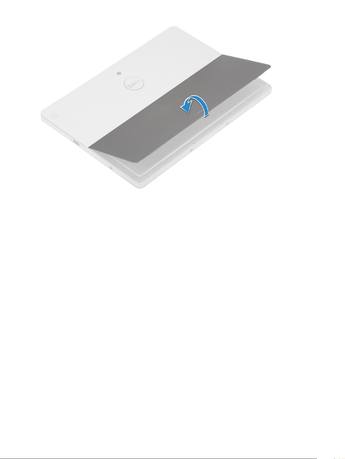
2 Open the kickstand by holding the tablet vertically and pressing it down. Place the tablet with the display facing down.
NOTE
: You can also open the kickstand from the speaker recess area.
NOTE: SIM card slot is available only on tablets shipping with WWAN module.
3 Place the tablet on a at surface and lift the stand to reveal the base of the tablet.
NOTE
: Ensure to open the kickstand to 145 degrees.
Disassembly and reassembly 7
Page 8
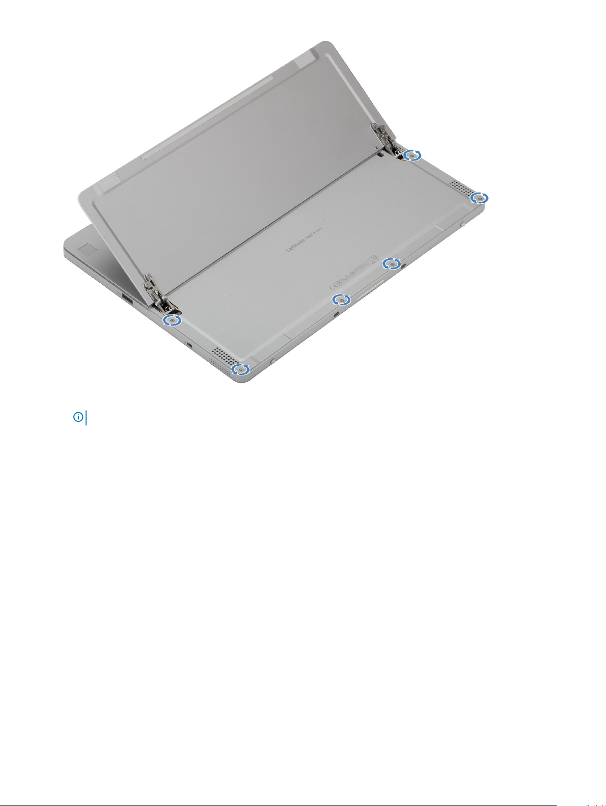
4 To release the display panel assembly:
a Loosen the six captive screws securing the display back assembly in place.
b Close the kickstand [2] and ip the tablet to view the display.
8
Disassembly and reassembly
Page 9
5 Use a plastic scribe [1] to pry the edges [2] of the display panel starting from the bottom side rst (near the docking port).
NOTE
: Flip the tablet so the LCD is upward.
Disassembly and reassembly 9
Page 10
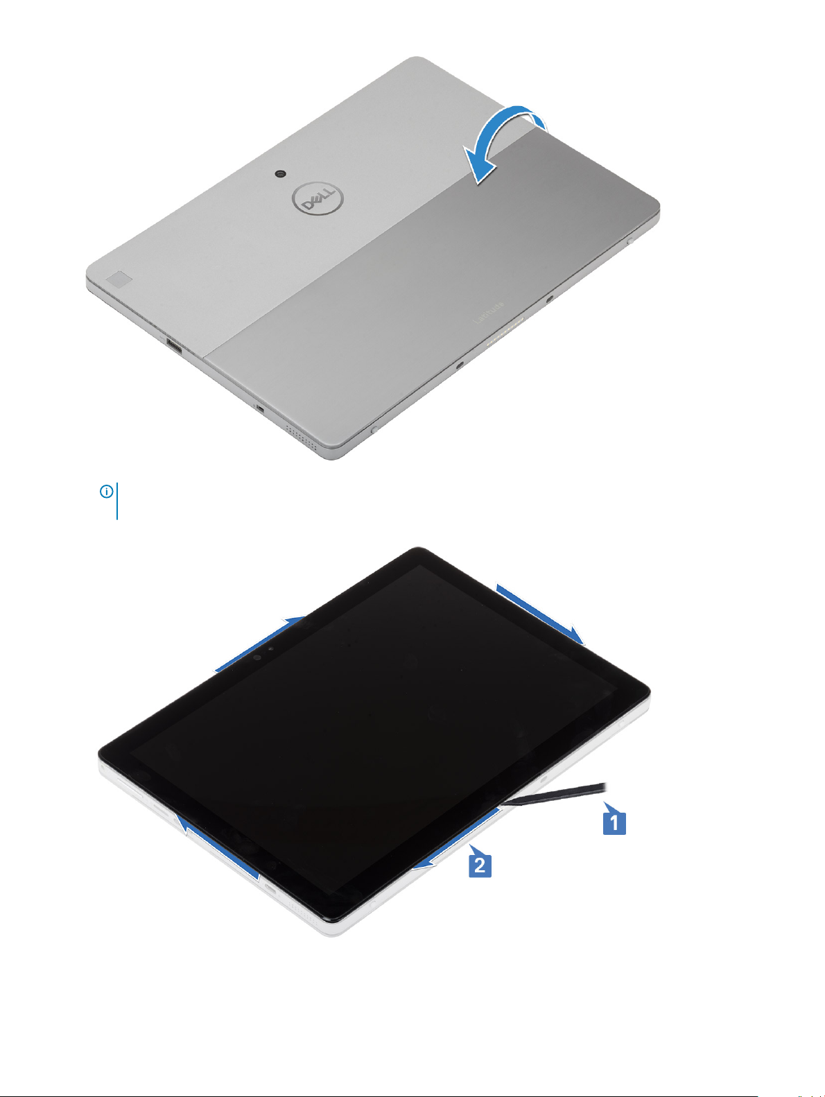
NOTE: Ensure to pry from the docking port and gently moving clockwise to avoid damage to the plastic clips. Use a
plastic scribe.
6 Flip the display panel on a plane surface with the LCD panel upwards.
Disassembly and reassembly
10
Page 11
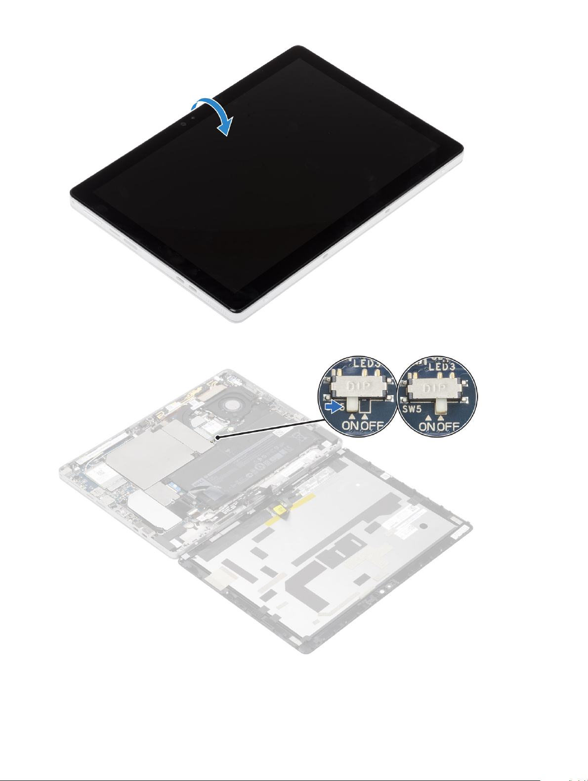
7 Slide the power switch on the system board to OFF.
8 Remove the two M2.5 X 3 screws securing the display cable bracket to the system board, and remove the display cable bracket.
Disassembly and reassembly
11
Page 12
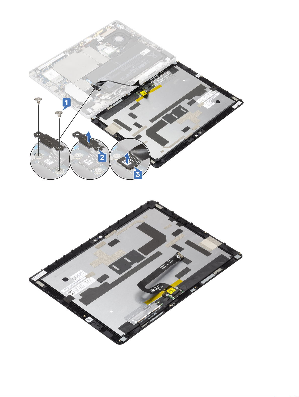
9 Disconnect the display cable from the system board and remove the display panel assembly from the system.
12
Disassembly and reassembly
Page 13
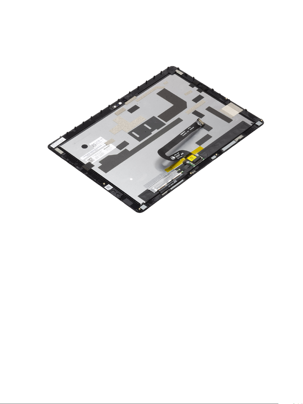
Installing the display panel assembly
1 Place the display panel on a plane surface.
2 Connect the display cable to the connector on the system board
Figure 1. Connect the display cable
3 Connect the battery cable to the connector on the system board.
Disassembly and reassembly
13
Page 14
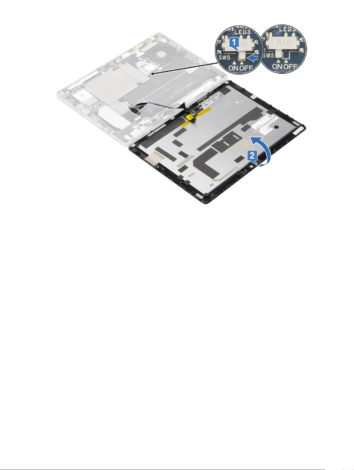
Figure 2. Connect the battery cable
4 Install the display panel on the tablet and press the edges until they snap in.
14
Disassembly and reassembly
Page 15
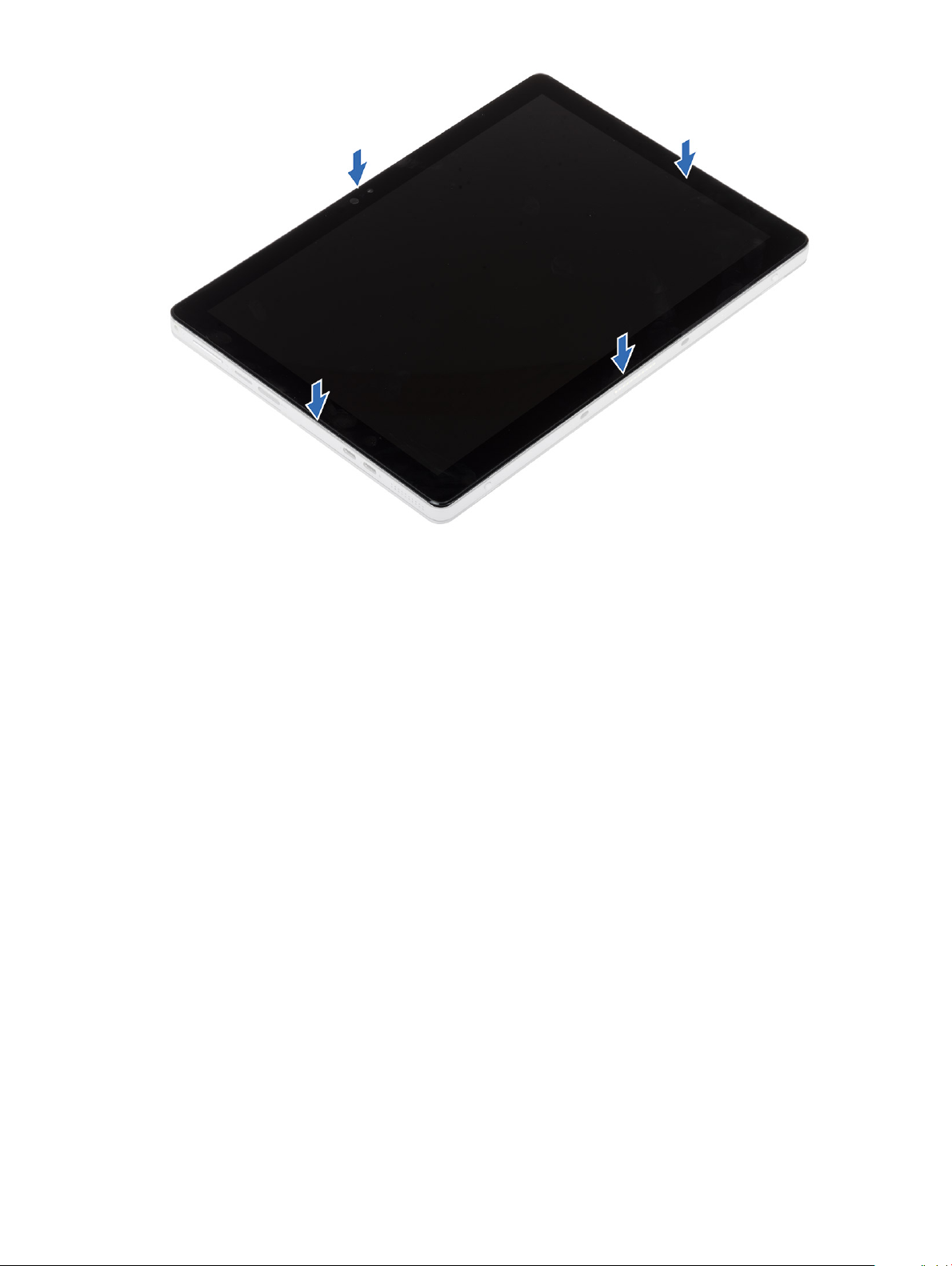
Figure 3. Install the display panel
5 Flip the tablet and open the kickstand.
Disassembly and reassembly
15
Page 16
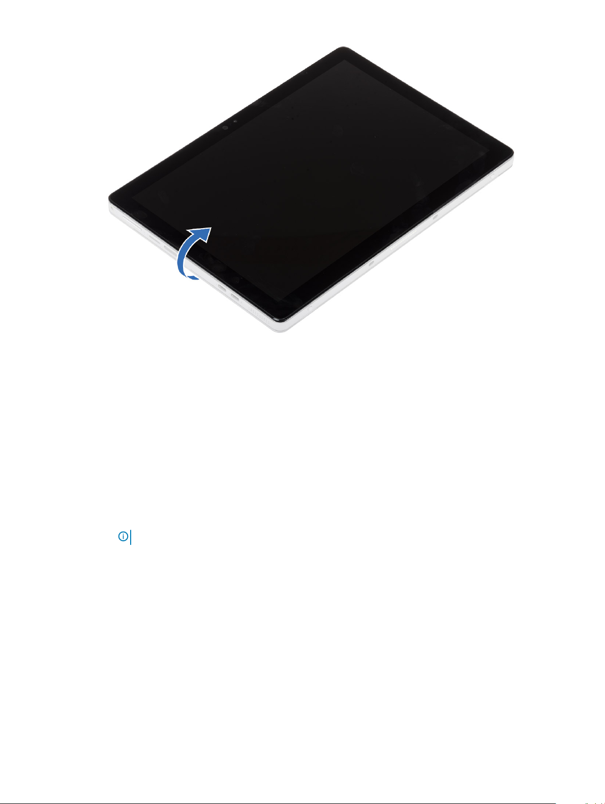
Figure 4. Flip the tablet
6 Replace the M1.6 x 3 screws to secure the tablet to the display panel.
Solid State Drive (SSD)
Removing the SSD module
1 Follow the procedure in before working inside your tablet.
2 Remove the:
a Remove the SIM card and display panel.
NOTE
: SIM card slot is available only on tablets shipping with WWAN module.
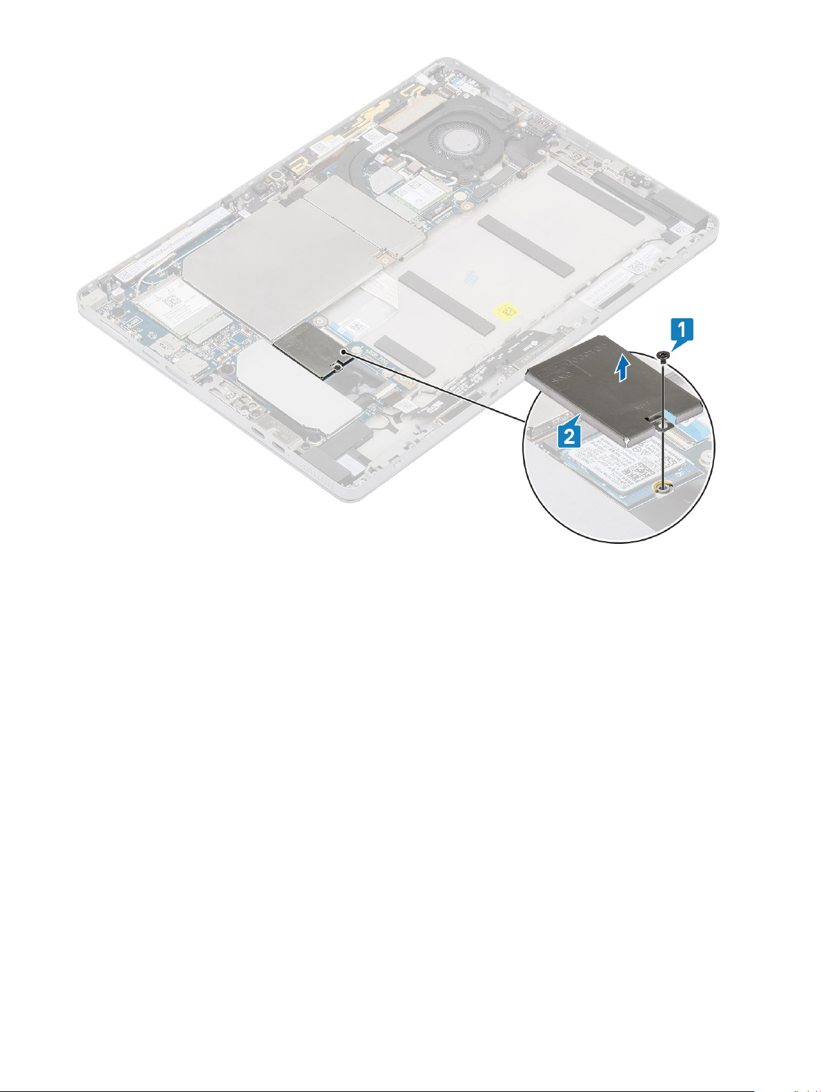
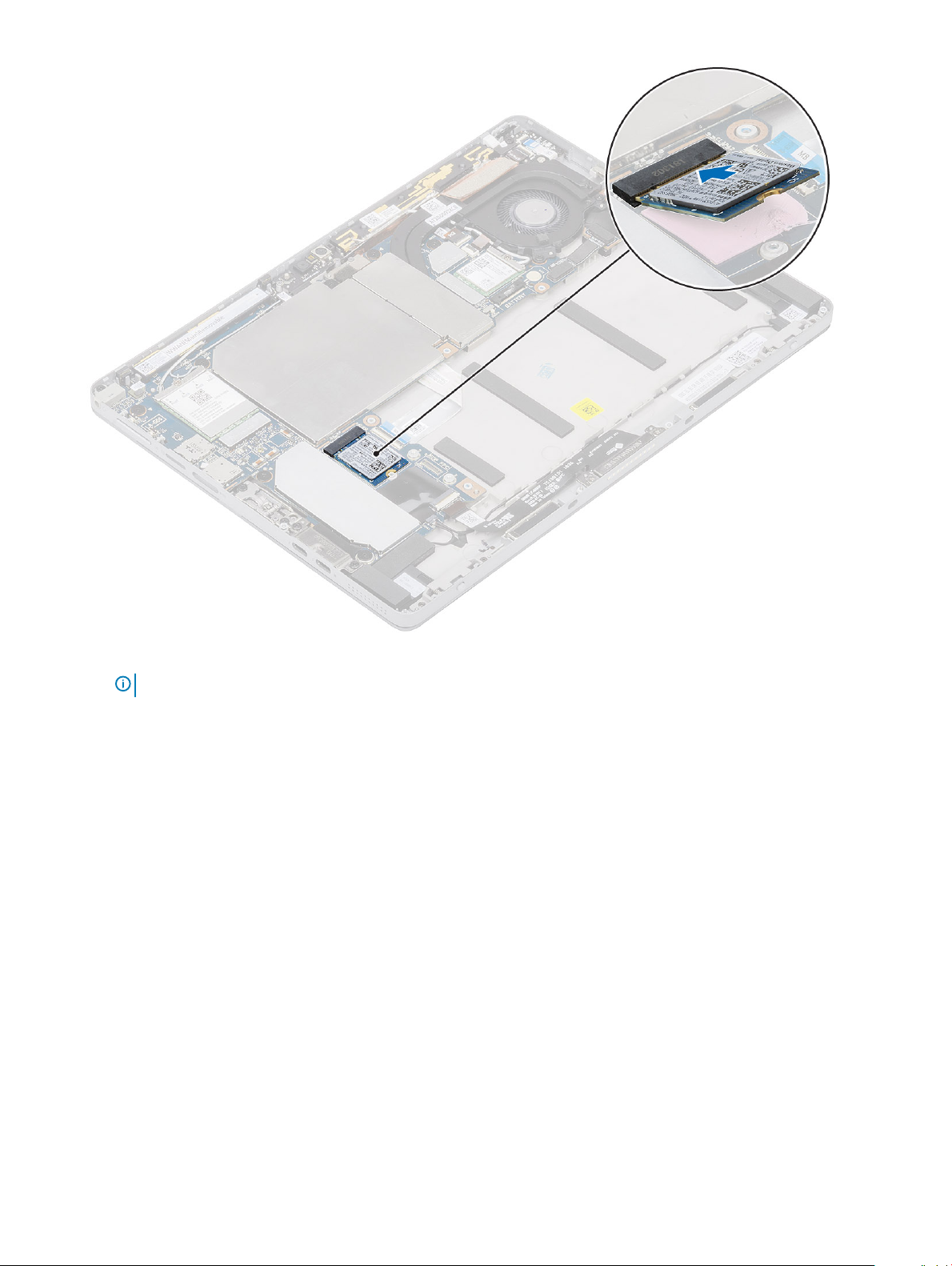
3 To remove the SSD module:
a Remove the single M2 x 2.5 screw securing the M.2 2230 SSD shielding cover.
Disassembly and reassembly
16
Page 17
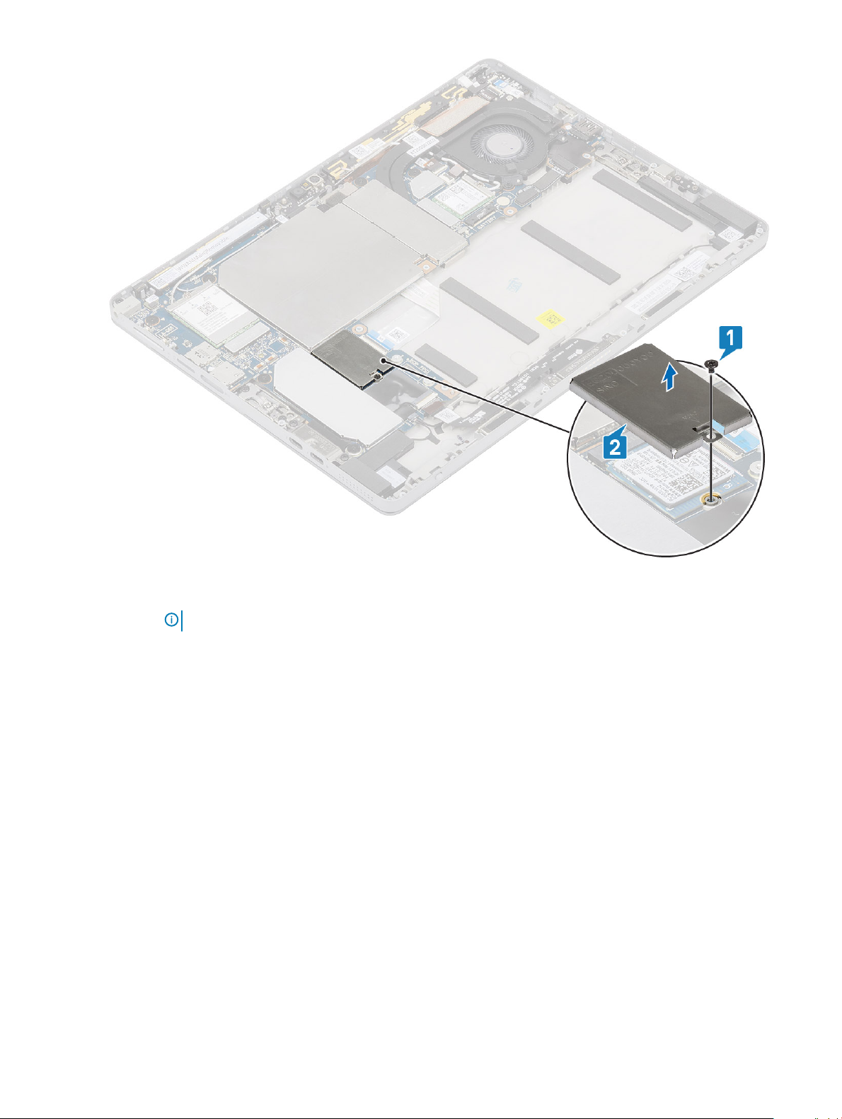
b Lift the M.2 2230 SSD shielding cover from the tablet.
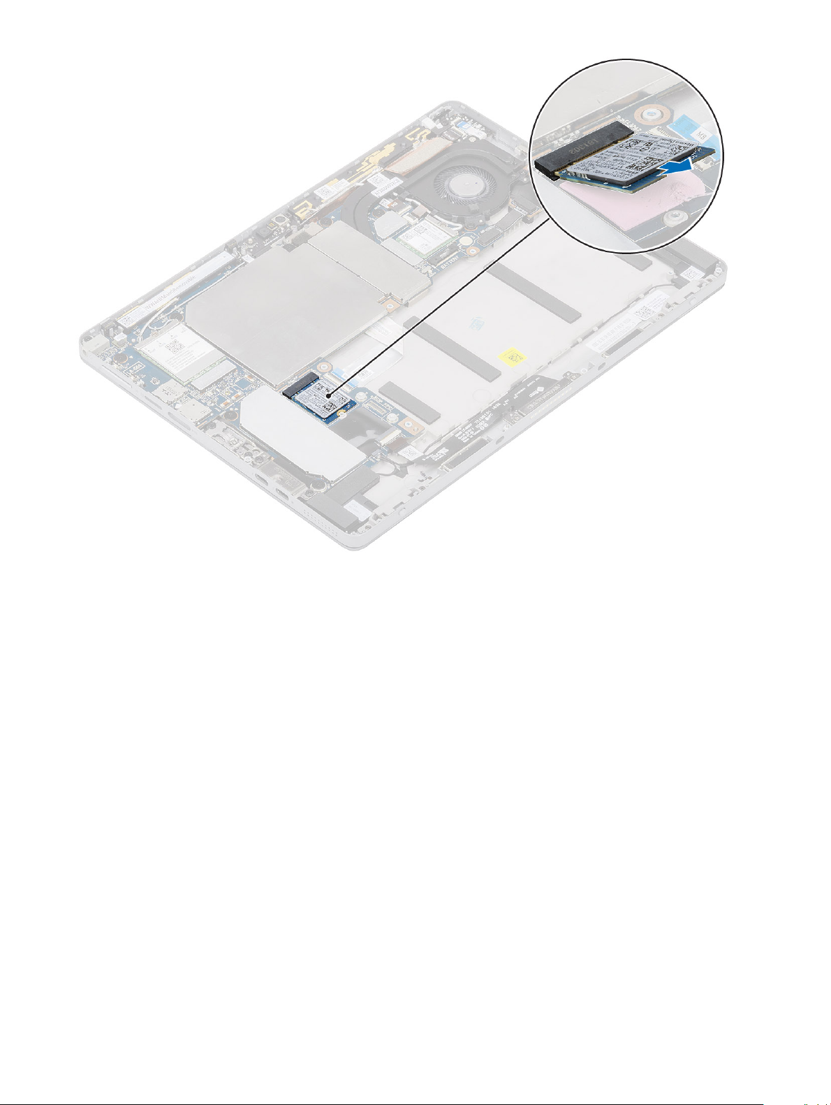
c Slide and lift the SSD module from the slot on the tablet.
NOTE
: Ensure NOT to lift the SSD card by an angle more than 15°.
Disassembly and reassembly 17
Page 18
18 Disassembly and reassembly
Page 19
Installing SSD module
1 Insert the SSD module into the slot on the system board.
Disassembly and reassembly
19
Page 20
2 Replace the M2 x 2.5 screw to secure SSD shield.
NOTE
: Align the shield carefully to avoid damage to the clips heads.
20 Disassembly and reassembly
Page 21

WLAN card
Removing the WWAN card
1 Follow the procedure explained in Before working on your tablet.
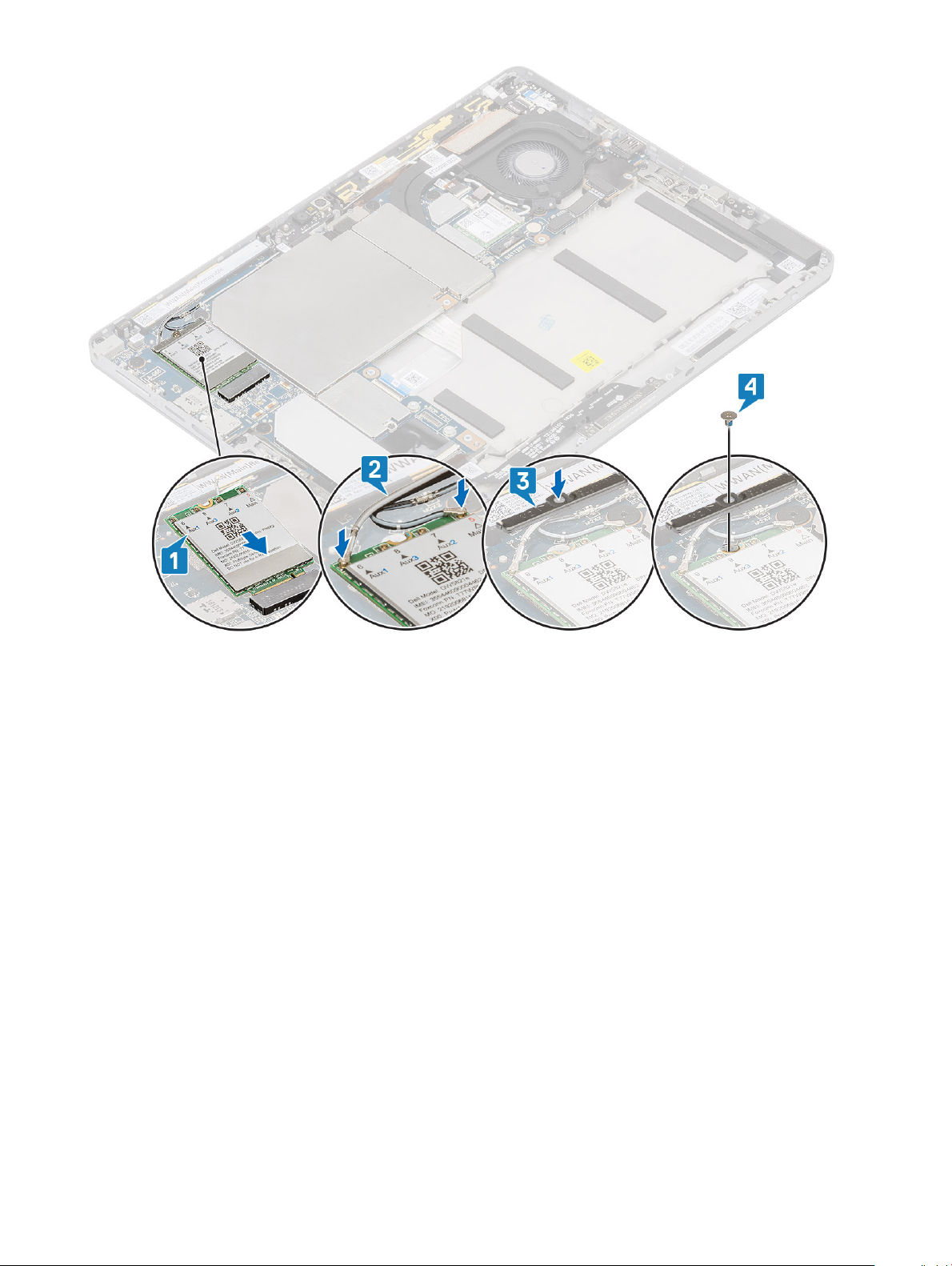
2 To remove the WWAN card:
a Remove the single captive screw securing the WWAN card bracket in place.
b Remove the WWAN card bracket.
c Disconnect any antennas connected to the WWAN card.
d Remove the WWAN card from the system.
Disassembly and reassembly
21
Page 22
Installing the WWAN card
1 Insert the WWAN card into the connector on the system board.
2 Connect the antenna cables to the WWAN card.
3 Insert the WWAN bracket to the WWAN card.
4 Replace the M2 x 3.5 screw to secure WWAN bracket.
22
Disassembly and reassembly
Page 23

5 Install the:
a Display panel
b SIM card
6 Follow the procedure in After working inside your tablet.
Disassembly and reassembly
23
Page 24

Battery
Lithium-ion battery precautions
CAUTION:
• Exercise caution when handling Lithium-ion batteries.
• Discharge the battery as much as possible before removing it from the system. This can be done by disconnecting the AC adapter
from the system to allow the battery to drain.
• Do not crush, drop, mutilate, or penetrate the battery with foreign objects.
• Do not expose the battery to high temperatures, or disassemble battery packs and cells.
• Do not apply pressure to the surface of the battery.
• Do not bend the battery.
• Do not use tools of any kind to pry on or against the battery.
• If a battery gets stuck in a device as a result of swelling, do not try to free it as puncturing, bending, or crushing a Lithium-ion
battery can be dangerous. In such an instance, the entire system should be replaced. Contact https://www.dell.com/support for
assistance and further instructions.
• Always purchase genuine batteries from https://www.dell.com or authorized Dell partners and re-sellers.
Removing the battery
1 Follow the procedure in Before working inside your tablet.
2 Remove the:
a Remove the SIM card
NOTE
: SIM card slot is available only on tablets shipping with WWAN module.
b Remove the display panel.
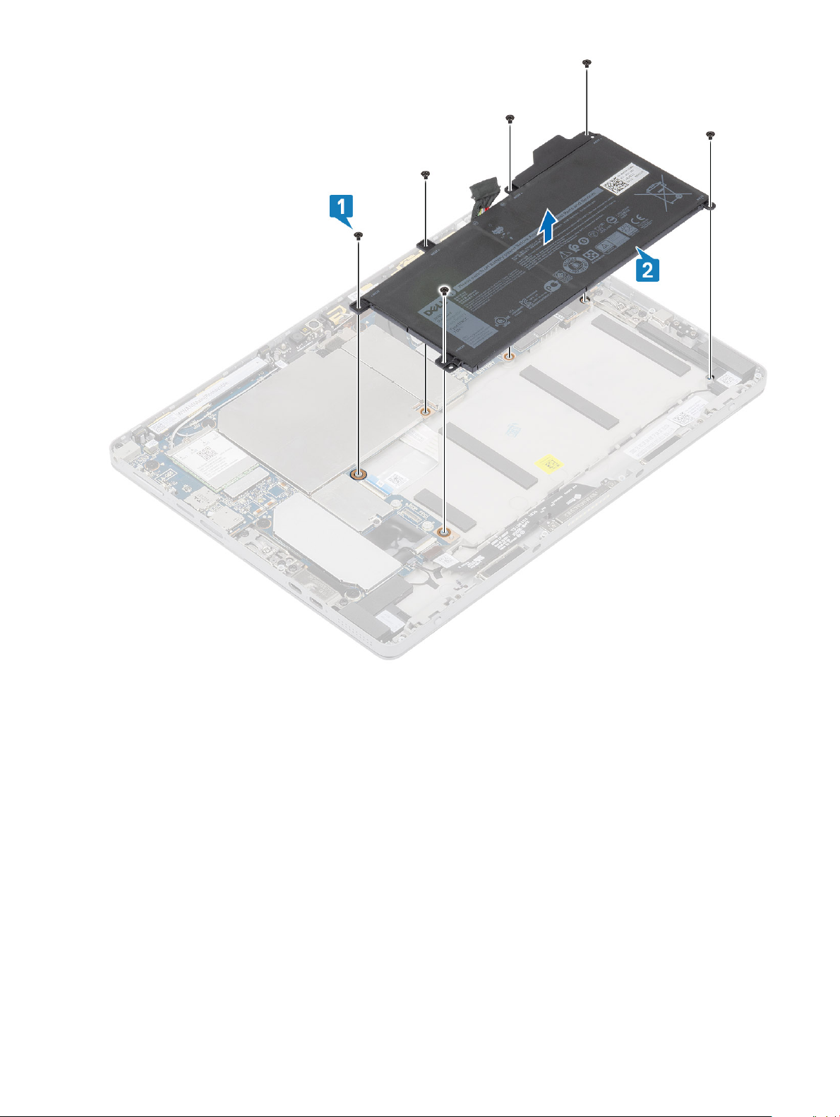
3 To remove the battery:
a Peel back the tape covering the battery connector.
24
Disassembly and reassembly
Page 25
b Remove the M2 X 4 screws securing the battery in place.
c Gently lift up the battery from its compartment on the display back cover and disconnect the battery cable from the system
board.
d Remove the battery from the system.
Disassembly and reassembly
25
Page 26
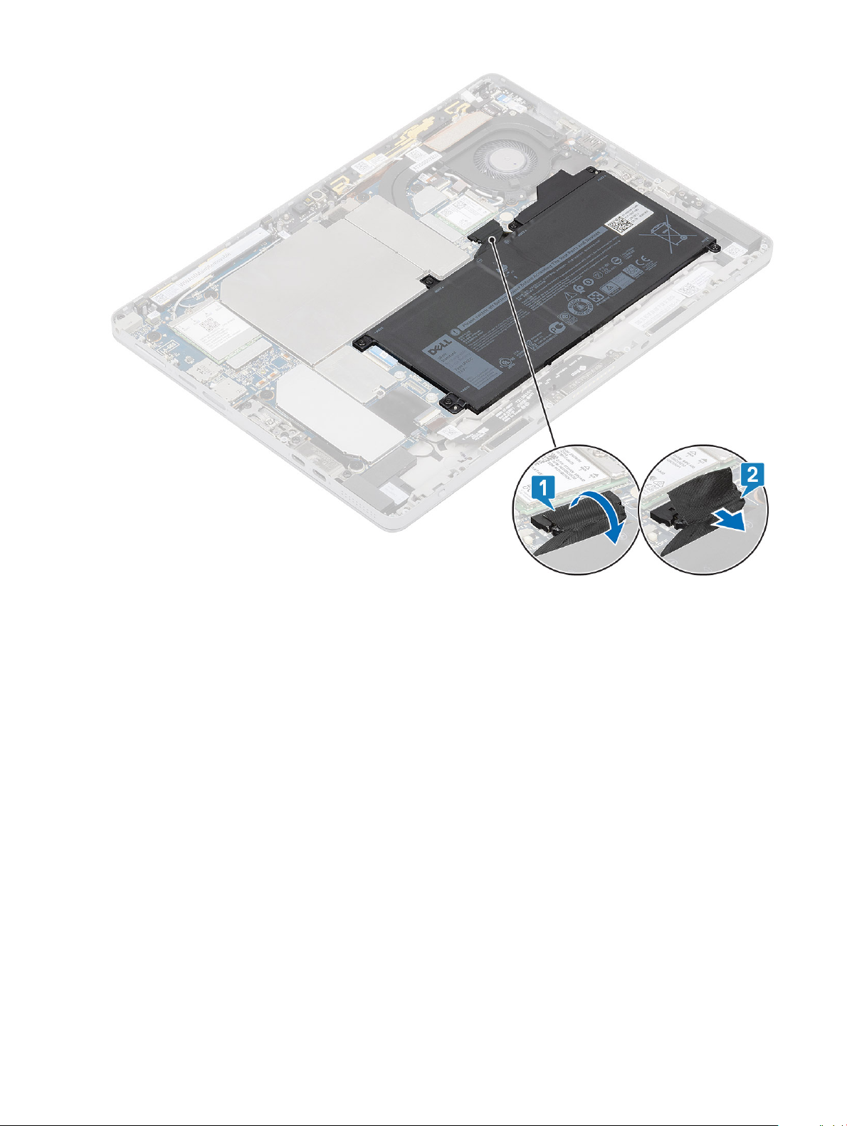
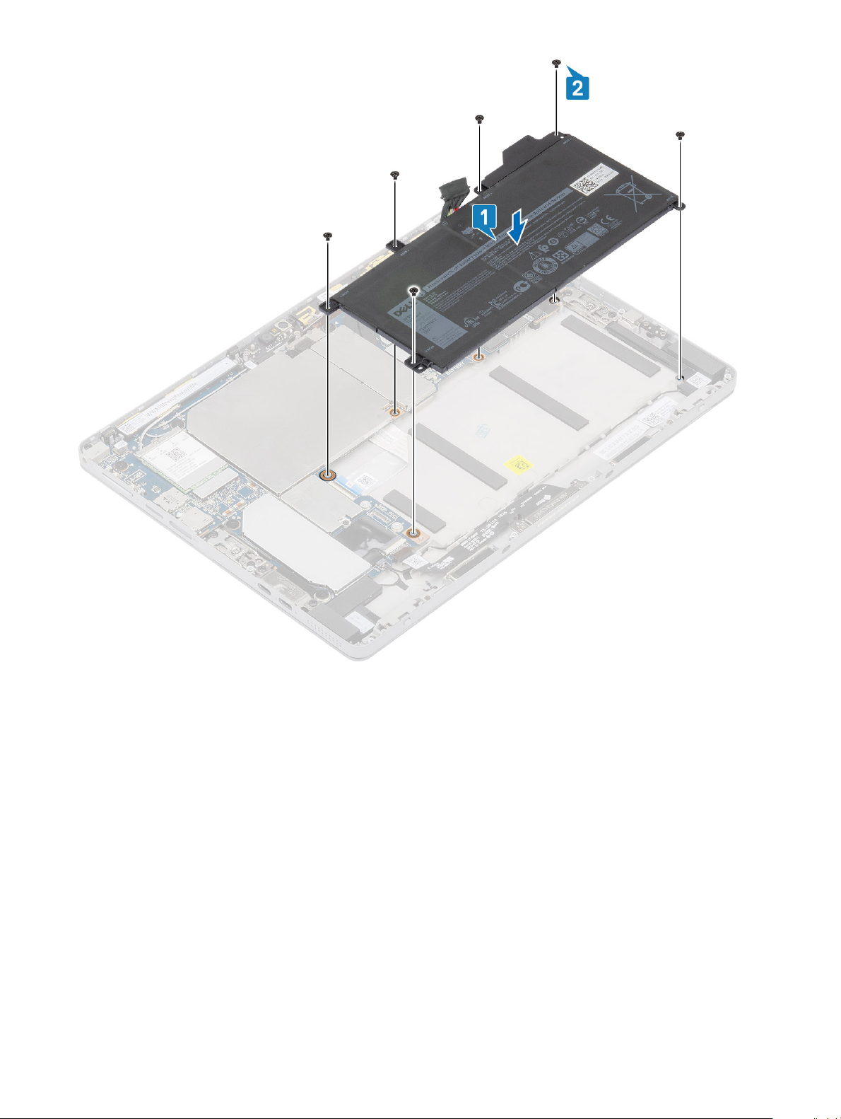
Installing the battery
1 Insert the battery into the slot on the tablet [1].
2 Replace the M2 x 4 screws to secure the battery to the tablet [2].
26
Disassembly and reassembly
Page 27
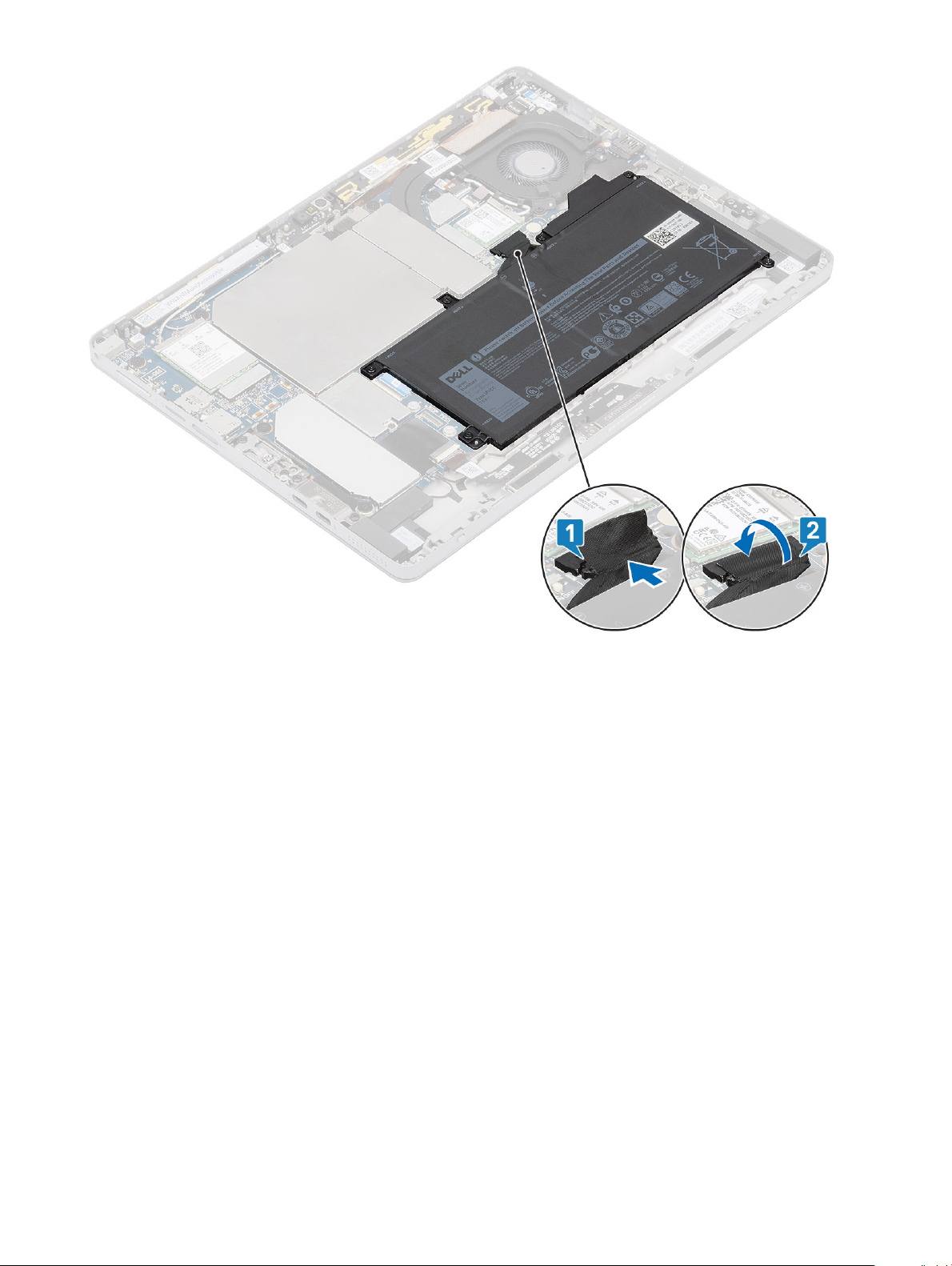
3 Connect the battery connector to the system board and x the adhesive tape that secures the connector.
Disassembly and reassembly
27
Page 28
4 Install the:
a Display panel.
b SIM card.
5 Follow the procedure in After working inside your tablet.
Heat Sink
Removing heatsink
1 Follow the procedure in Before working inside your tablet.
2 Remove the:
a SD memory card and Wireless card
b Display panel.
3 To remove the heatsink assembly:
a Using a plastic scribe, gently remove the left and right shielding covers covering the heatsink starting from the edges marked
with an arrow.
Disassembly and reassembly
28
Page 29
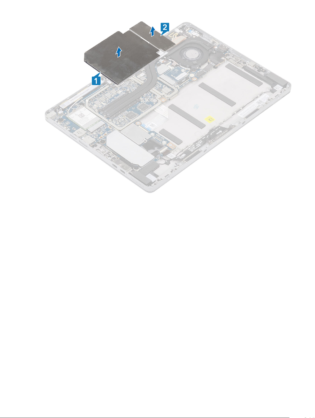
Figure 5. Remove heatsink shielding cover
b Unthread the wireless antennas from the routing channels next to the fan, and disconnect the fan cable from the system board.
Disassembly and reassembly
29
Page 30

4 Disconnect the fan cable from the system board.
5 Remove the three MXX screws securing the fan in place and loosen the four captive screws (1>2>3>4) securing the heatsink in place.
6 Remove the thermal assembly from the system.
Installing heat sink
1 Follow the procedure in Before working inside your tablet.
2 Remove the:
3 To install the heat sink assembly:
a Place the thermal assembly inside the system.
30
Disassembly and reassembly
Page 31

Disassembly and reassembly 31
Page 32

b Tighten the captive screws securing the heatsink in place and place and tighten the three M2 X 2.5 screws.
c Route and x the cable to the system board, tighten the wireless antenna in place.
32
Disassembly and reassembly
Page 33

4 Install the SD Memory Card, Display Panel Assembly and Wireless Card.
Speaker
Removing the speaker
1 Follow the procedure in Before working inside your tablet.
2 Remove the:
a SIM card.
NOTE
: SIM card slot is available only on tablets shipping with WWAN module.
b Display panel.
c Docking Connector.
3 To remove the speaker:
a Disconnect the speaker cable from the system board [1].
Disassembly and reassembly
33
Page 34

b Remove the speaker cable from it's routing channels [2].
34
Disassembly and reassembly
Page 35

c Using a plastic scribe, peel o and remove both the speakers from the system.
Disassembly and reassembly
35
Page 36

Installing speaker
1 Insert the speaker in the block on the system board.
36
Disassembly and reassembly
Page 37

2 Connect the cables to the system board.
Disassembly and reassembly
37
Page 38

3 Press the speaker and insert it in the slot in the tablet.
38
Disassembly and reassembly
Page 39

4 Install the:
a Display panel.
b SIM card.
c Docking Connector.
5 Follow the procedure in After working inside your tablet.
Front facing camera
Removing front camera
1 Follow the procedure in Before working inside your tablet.
2 Remove the:
a SD memory card.
b Display panel
3 To remove the front camera:
a Using a plastic scribe, gently pry open and remove the left shielding cover from the edge marked with an arrow.
b Disconnect the front-facing camera cable from the system board.
c Use a plastic scribe to pry and disconnect the front camera cable [3]
: Ensure to peel o the adhesive tape that secures the front camera to the rear camera. The front
NOTE
camera cable is glued to the rear camera, ensure to gently peel o, to remove the screw that secures the
rear camera to the system board.
d Remove the M1.6 x 3 screws securing the front camera module to the system chassis.
e Peel o and lift the front camera module from the tablet.
Disassembly and reassembly
39
Page 40

40 Disassembly and reassembly
Page 41

Installing the front camera
1 Insert the camera module into the slot on the tablet.
2 Replace the M1.6 x 3 screws to secure the front camera module.
Disassembly and reassembly
41
Page 42

3 Connect the front camera cable to the system board.
4 Place the shielding cover to secure the front camera module.
NOTE
: Handle the covering shield with care else it may break.
5 Ax the camera module, and shielding cover.
42
Disassembly and reassembly
Page 43

6 Install the:
a Display panel.
b SD memory card.
7 Follow the procedure in After working inside your tablet.
Rear facing camera
Removing the rear camera
1 Follow the procedure in Before working inside your tablet.
2 Remove the:
a SD memory card.
b Display panel.
3 To remove the rear camera:
a Using a plastic scribe, gently pry open and remove the right shielding cover from the edge marked with an arrow.
b Disconnect the rear camera cable from the system board.
c Remove the M1.6 x 3 screw securing the rear camera module.
d Lift the camera module from the tablet.
Disassembly and reassembly
43
Page 44

44 Disassembly and reassembly
Page 45

Installing rear camera
1 Follow the procedure in Before working inside your tablet.
2 To install the rear camera:
a Place the camera module on the tablet.
b Tighten the M1.6 x 3 screw securing the rear camera module.
c Fix the rear camera cable on the system board.
Disassembly and reassembly
45
Page 46

46 Disassembly and reassembly
Page 47

3 Install the:
a SD memory card.
b Display panel
Smart Card Cage
Removing the smart card cage
1 Follow the procedure in Before working inside your tablet.
2 Remove the SD Memory Card, SIM Card Tray or Dummy SIM Card Tray (for models shipped with a WWAN card), Display Panel
Assembly, Battery, M.2 2230 SSD, Wireless Card, WWAN card (for models shipped with a WWAN card), Rear-Facing Camera, Thermal
Assembly, Dummy WWAN Main Antenna Module, WWAN Main Antenna Module (for models shipped with a WWAN card), and System
Board.
3 To remove the smart card cage:
a Disconnect and peel back the Smartcard cage FFC from the daughter board.
b Remove the M2.0 x 2.5 screws from the smart card module [1].
c Lift the smart card cage from the tablet [2].
Disassembly and reassembly
47
Page 48

48 Disassembly and reassembly
Page 49

Installing the smart card cage
1 Insert the smart cage into the slot on the tablet.
2 Replace the M2 x 2.5 screws [2] to secure the smart card cage to the tablet [1].
3 Connect the smart cable to the smart card module.
Disassembly and reassembly 49
Page 50

4 Remove the SD Memory Card, SIM Card Tray or Dummy SIM Card Tray (for models shipped with a WWAN card), Display Panel
Assembly, Battery, M.2 2230 SSD, Wireless Card, WWAN card (for models shipped with a WWAN card), Rear-Facing Camera, Thermal
Assembly, Dummy WWAN Main Antenna Module, WWAN Main Antenna Module (for models shipped with a WWAN card), and System
Board.
5 Follow the procedure in After working inside your tablet.
Docking board
Removing the docking connector
1 Follow the procedure in Before working inside your tablet.
2 Remove the:
a SD memory card.
b Display panel.
3 To remove the docking connector:
a Disconnect and peel back the docking connector FPC from the system board.
Disassembly and reassembly
50
Page 51

b Remove the M2 x 2 screws securing the docking board bracket to the docking board.
Disassembly and reassembly
51
Page 52

c Remove the docking connector along with its FPC from the system.
52
Disassembly and reassembly
Page 53

Installing the docking board
1 Insert the docking board and docking board bracket into the slot on the tablet.
Disassembly and reassembly
53
Page 54

2 Replace the M2 x 2 screws to secure the docking board to the tablet.
54
Disassembly and reassembly
Page 55

3 Ax the docking board cable on the tablet,
4 Connect the docking board cable to the connector on the system board.
Disassembly and reassembly
55
Page 56

5 Install the:
a Display panel
b SD memory card.
6 Follow the procedure in After working inside your tablet.
Power Button Board
Removing the power button daughter board
1 Follow the procedure in Before working inside your tablet.
2 Remove the SD Memory Card, Display Panel Assembly, Battery, and Thermal Assembly.
3 Unthread any wireless antennas covering the power button daughter board FPC.
Disassembly and reassembly
56
Page 57

Figure 6. Unthread wireless antennas
4 Disconnect and peel back the power button daughter board FPC from the system board.
5 Disconnect and peel back the ngerprint reader FFC from the power button daughter board.
6 Remove the two M2 X 2.5 screws securing the power button daughter board in place.
Disassembly and reassembly
57
Page 58

Figure 7. Remove the FFC
7 Using a plastic scribe, pry the power button sensor at the top edge of the power button daughter board out of its compartment.
8 Remove the power button daughter board along with its FPC from the display back cover.
9 Disconnect the power button daughter board FPC from the power button daughter board.
58
Disassembly and reassembly
Page 59

Figure 8. Disconnect and remove the power button board
Installing the power button board
1 Follow the procedure in Before working inside your tablet.
2 Fix the daughter board along with its FPC from the display back cover.
Disassembly and reassembly
59
Page 60

Figure 9. Fix the daughter board with the FPC
3 Fix the two M2 X 2.5 screws securing the power button daughter board in place.
4 Install the ngerprint reader FFC on the power button daughter board.
60
Disassembly and reassembly
Page 61

Figure 10. Install the FPC
5 Thread any wireless antennas covering the power button daughter board FPC.
Disassembly and reassembly
61
Page 62

Figure 11. Thread the wireless antenna
6 Fix the SD Memory Card, Display Panel Assembly, Battery, and Thermal Assembly.
System Board
Removing system board
1 Follow the procedure in Before working inside your tablet.
2 Remove the SD Memory Card, SIM Card Tray or Dummy SIM Card Tray (for models shipped with a WWAN card), Display Panel
Assembly, Battery, M.2 2230 SSD, Wireless Card, WWAN card (for models shipped with a WWAN card), Front-Facing Camera,
Infrared Camera (for models shipped with an Infrared Camera), Rear-Facing Camera, Microphone Module-A, Microphone Module-B,
Thermal Assembly, Dummy WWAN Main Antenna Module, and WWAN Main Antenna Module (for models shipped with a WWAN
card).
3 Disconnect the following cables from the system board .
Disassembly and reassembly
62
Page 63

a Push the release latch of on the SIM card cage inward to release the
dummy SIM card tray.
b Remove the dummy SIM card tray.
c Disconnect the power button daughter board FPC, USB daughter board FPC, USH FFC (that are shipped with a USH module),
docking connector FPC, and a speaker cable.
4 Un-route the antenna cables from the routing clips .
Disassembly and reassembly
63
Page 64

64 Disassembly and reassembly
Page 65

5 To remove the system board
a Remove the two bracket M2 x 2.5 screws securing the Type-C USB bracket in place.
b Remove the Type-C USB bracket.
c Remove the single M2 x 2.5 screw securing the audio jack in place.
d Remove the seven M2 x 2.5 screws securing the system board in place
Disassembly and reassembly
65
Page 66

e Lift the system board from the tablet [2].
Installing system board
1 Align the system board with the screw holders on the tablet.
2 Tighten the seven M2 x 2.5 screws to secure the system board to the tablet.
NOTE
: Remember to align the Type-C port and tighten the two screws to secure the port to the system chassis.
66 Disassembly and reassembly
Page 67

3 Tighten the single M2 x 2.5 screw securing the audio jack in place and place the USB Type-C bracket.
4 Tighten the two bracket M2 x 2.5 screws securing the Type-C USB bracket in place.
Disassembly and reassembly
67
Page 68

68 Disassembly and reassembly
Page 69

5 Remove the SD Memory Card, SIM Card Tray or Dummy SIM Card Tray (for models shipped with a WWAN card), Display Panel
Assembly, Battery, M.2 2230 SSD, Wireless Card, WWAN card (for models shipped with a WWAN card), Front-Facing Camera,
Infrared Camera (for models shipped with an Infrared Camera), Rear-Facing Camera, Microphone Module-A, Microphone Module-B,
Thermal Assembly, Dummy WWAN Main Antenna Module, and WWAN Main Antenna Module (for models shipped with a WWAN
card).
6 Follow the procedure in After working inside your tablet.
System Board
Removing I/O board
1 Follow the procedure in Before working inside your tablet.
2 Remove the SD Memory Card and display panel.
3 Remove the cable from the system board, and peel o the adhesive tape to remove the I/O board
Figure 12. Removing the cable
Disassembly and reassembly
69
Page 70

Figure 13. Peel o the adhesive tape
Installing I/O board
1 Follow the procedure in Before working inside your tablet.
2 Remove the SD Memory Card and display panel.
3 Fix the adhesive tape and Install the cable with the I/O board to the system board.
70
Disassembly and reassembly
Page 71

Figure 14. Fix the adhesive tape
Disassembly and reassembly
71
Page 72

Figure 15. Fix the I/O module
Antenna
Removing the antenna module
1 Follow the procedure in Before working inside your tablet.
2 Remove:
a SD memory card.
b Display panel
3 To remove the antenna module:
a Unthread the WWAN main antenna from the system board.
b Release the clips on the left and right side of the WWAN main antenna module securing it to the system
c Flip over the WWAN main antenna module to release it from the system board.
d Remove the WWAN main antenna module from the system.
: The same procedure must be followed to remove the dummy WWAN main antenna module from the system.
NOTE
72 Disassembly and reassembly
Page 73

Disassembly and reassembly 73
Page 74

Installing the antenna module
1 Insert the antenna module into the slot on the back cover of the tablet.
2 Flip over the WWAN main antenna module to x it to the system board..
74 Disassembly and reassembly
Page 75

3 Tighten the clips on the left and right side of the WWAN main antenna module securing it to the system.
4 Thread the WWAN main antenna to the system board.
5 Install the:
a Display panel
b SD memory card.
6 Follow the procedure in After working inside your tablet.
Disassembly and reassembly
75
Page 76

This chapter details the supported operating systems along with instructions on how to install the drivers.
Downloading Windows drivers
1 Turn on the tabletdesktopnotebook.
2 Go to Dell.com/support.
3 Click Product Support, enter the Service Tag of your tabletdesktopnotebook, and then click Submit.
NOTE: If you do not have the Service Tag, use the auto detect feature or manually browse for your
tabletdesktopnotebook model.
4 Click Drivers and Downloads.
5 Select the operating system installed on your tabletdesktopnotebook.
6 Scroll down the page and select the driver to install.
7 Click Download File to download the driver for your tabletdesktopnotebook.
8 After the download is complete, navigate to the folder where you saved the driver le.
9 Double-click the driver le icon and follow the instructions on the screen.
3
Software
76 Software
Page 77

System setup
System setup enables you to manage your tabletdesktopnotebook hardware and specify BIOS level options. From the System setup, you
can:
• Change the NVRAM settings after you add or remove hardware
• View the system hardware conguration
• Enable or disable integrated devices
• Set performance and power management thresholds
• Manage your computer security
Topics:
• Entering BIOS without keyboard
• System setup options
• System Log
• Updating the BIOS
• Updating your system BIOS using a USB ash drive
• System and setup password
4
Entering BIOS without keyboard
1 Press the power button to turn on your tablet.
2 Press and hold the Volume Up button when the Dell logo appears on the screen.
3 When the F12 boot selection menu appears, select BIOS Setup using the Volume Up button.
4 Press the Volume Down button to enter BIOS setup program.
System setup options
: Depending on the tabletcomputerlaptop and its installed devices, the items listed in this section may or may not appear.
NOTE
General screen options
This section lists the primary hardware features of your computer.
Option
System Information
Description
• System Information: Displays BIOS Version, Service Tag, Asset Tag, Ownership Tag, Ownership Date,
Manufacture Date, and the Express Service Code.
• Memory Information: Displays Memory Installed, Memory Available, Memory Speed, Memory Channels Mode,
Memory Technology, DIMM A Size, DIMM B Size.
• Processor Information: Displays Processor Type, Core Count, Processor ID, Current Clock Speed, Minimum
Clock Speed, Maximum Clock Speed, Processor L2 Cache, Processor L3 Cache, HT Capable, and 64-Bit
technology.
System setup 77
Page 78

Option Description
• Device Information: Displays Primary Hard Drive, MiniCard Device, ODD Device, Dock eSATA Device, LOM
MAC Address, Video Controller, Video BIOS Version, Video Memory, Panel Type, Native Resolution, Audio
Controller, Wi-Fi Device, WiGig Device, Cellular Device, Bluetooth Device.
Battery Information Displays the battery status and the type of AC adapter connected to the computer.
Boot Sequence
Advanced Boot
Options
UEFI Boot Path
SecurityOptions
Boot Sequence Allows you to change the order in which the computer attempts to nd an operating
system. The options are:
• Windows Boot Manager
By default, the options is checked.
Boot List Options Allows you to change the boot list option:
• Legacy
• UEFI (The option is enabled by default)
Allows you the legacy option ROMs to load. By default, all the option are disabled.
• Enable Legacy Option ROMs
• Enable Attempt Legacy Boot
Allows you to control whether or not the system will prompt to the user to enter the Admin password, when a user
selects a UEFI boot path from the F12 boot Menu.
• Always, Except Internal HDD. This option is enabled by default.
• Always
• Never
NOTE: These options have no relevance if the Admin password is not set BIOS settings.
Date/Time Allows you to change the date and time.
System Conguration screen options
Option
SMART Reporting This eld controls whether hard drive errors for integrated drives are reported during system startup. This
USB Conguration
Description
technology is part of the SMART (Self-Monitoring Analysis and Reporting Technology) specication. This option is
disabled by default.
• Enable SMART Reporting
This is an optional feature.
This eld congures the integrated USB controller. If Boot Support is enabled, the system is allowed to boot any
type of USB Mass Storage Devices—HDD, memory key, oppy.
If USB port is enabled, device attached to this port is enabled and available for OS.
If USB port is disabled, the OS cannot see any device attached to this port.
78 System setup
Page 79

Option Description
The options are:
• Enable USB Boot Support—enabled by default
• Enable External USB Port—enabled by default
• Always Allow dell docks—enabled by default
NOTE: USB keyboard and mouse always work in the BIOS setup irrespective of these settings.
USB PowerShare This eld congures the USB PowerShare feature behavior. This option allows you to charge external devices using
the stored system battery power through the USB PowerShare port. This option is disabled by default
Audio This eld enables or disables the integrated audio controller. By default, the Enable Audio option is selected. The
options are:
• Enable Microphone—enabled by default
• Enable Internal Speaker—enabled by default
Keyboard
Illumination
Keyboard Backlight
Timeout on Battery
Keyboard Backlight
with AC
This eld lets you choose the operating mode of the keyboard illumination feature. The keyboard brightness level
can be set from 0% to 100%. The options are:
• Disabled—enabled by default
• Dim (50%)
• Bright
The Keyboard Backlight Timeout dims out with the Battery option. The main keyboard illumination feature is not
aected. Keyboard Illumination will continue to support the various illumination levels. This eld has an eect when
the backlight is enabled. The options are:
• 5 sec
• 10 sec—enabled by default
• 15 sec
• 30 sec
• 1 min
• 5 min
• 15 min
• Never
The Keyboard Backlight with AC option does not aect the main keyboard illumination feature. Keyboard
Illumination will continue to support the various illumination levels. This eld has an eect when the backlight is
enabled. This option is enabled by default.
Keyboard Backlight
Timeout on AC
The Keyboard Backlight Timeout dims out with AC option. The main keyboard illumination feature is not aected.
Keyboard Illumination will continue to support the various illumination levels. This eld has an eect when the
backlight is enabled. The options are:
• 5 sec
• 10 sec—enabled by default
• 15 sec
• 30 sec
• 1 min
• 5 min
• 15 min
• Never
System setup 79
Page 80

Option Description
Unobtrusive Mode This option, when enabled, pressing Fn+F7 turns o all light and sound emissions in the system. To resume normal
operation, press Fn+F7 again. This option is disabled by default.
Miscellaneous
Devices
Allows you to enable or disable the following devices:
• Enable Front Camera—enabled by default
• Enable Back Camera—enabled by default
• Secure Digital (SD) card—enabled by default
• Secure Digital (SD) card boot
• Secure Digital (SD) card read-only-mode
System Conguration screen options
Option Description
Integrated NIC Allows you to controls the on-board LAN controller. The options are:
• DisabledThe internal LAN in o and not visible to the operating system.
• EnabledThe internal LAN is enabled.
• Enabled w/PXEThe internal LAN is enabled (with PXE boot). This option is enabled by default.
Drives Allows you to congure the various drives on board. All drives are enabled by default. The option is:
• M.2 2230 PCI-e SSD
SMART Reporting This eld controls whether hard drive errors for integrated drives are reported during system startup. This
technology is part of the SMART (Self Monitoring Analysis and Reporting Technology) specication. This option is
disabled by default.
• Enable SMART Reporting
USB Conguration
Dell Type-C dock
conguration
This is an optional feature.
This eld congures the integrated USB controller. If Boot Support is enabled, the system is allowed to boot any
type of USB Mass Storage Devices (HDD, memory key, oppy).
If USB port is enabled, device attached to this port is enabled and available for OS.
If USB port is disabled, the OS cannot see any device attached to this port.
The options are:
• Enable USB Boot Support
• Enable External USB Port
NOTE: Both the option is enabled by default.
Allows you to enable docks. The options are:
• Always Allow Dell DocksThis option is enabled by default.
• When set to enabled, allows connection to the Dell WD and TB family of docks (Type-C docks) independent of
USB and Thunderbolt Adapter conguration settings.
• When set to disabled, the docks will be controlled via the USB and Thunderbolt Adapter conguration settings.
80 System setup
Page 81

Option Description
Thunderbolt
Adapter
conguration:
USB PowerShare Allows you to charge external devices using the stored system battery power through the USB PowerShare port.
Audio Allows you to enable or disable the integrated audio controller. By default, the Enable Audio option is selected. The
Keyboard
Illumination
Allows you to congure the Thunderbolt™ adapter security settings within the Operating System.
NOTE: Security Levels are not applicable or enforced in the Pre-boot environment.
The options are:
• Enable Thunderbolt™ Technology SupportThis option is enabled by default.
• Enable Thunderbolt™ Adapter Boot Support
• Enable Thunderbolt™ Adapter Pre-boot Modules
• Security level - No Security
• Security level - User AuthorizationThis option is enabled by default.
• Security level - Secure Correct
• Security level - Display Port only
This eld can also congure the USB PowerShare feature behavior. By default, the Enable USB PowerShare is
disabled.
options are:
• Enable MicrophoneThis option is enabled by default.
• Enable Internal Speaker This option is enabled by default.
Allows you to choose the operating mode of the keyboard illumination feature. The keyboard brightness level can
be set from 0% to 100%. The options are:
Keyboard Backlight
Timeout on AC
Keyboard Backlight
Time-out on
Battery
• Disabled
• Dim
• Bright This option is enabled by default.
NOTE: The <Fn+F10> hotkey can be used to change the setting.
Allows you to dene the time-out value for the keyboard Backlight when an AC adapter is plugged into the system.
The main keyboard illumination feature is not aected. Keyboard Illumination will continue to support the various
illumination levels. This eld has an eect when the backlight is enabled. The options are:
• 5 seconds
• 10 seconds This option is enabled by default.
• 15 seconds
• 30 seconds
• 1 minute
• 5 minute
• 15 minute
• never
Allows you to dene the Keyboard Backlight Time-out dims out with Battery option. The main keyboard illumination
feature is not aected. Keyboard Illumination will continue to support the various illumination levels. This eld has
an eect when the backlight is enabled. The options are:
• 5 seconds
• 10 seconds This option is enabled by default.
• 15 seconds
• 30 seconds
System setup 81
Page 82

Option Description
• 1 minute
• 5 minute
• 15 minute
• never
Touchscreen Allows you to controls whether the touchscreen is enabled or disabled. By default, the option is enabled.
Unobtrusive Mode Allows you to select the option. When enabled, pressing Fn+F7 turns o all light and sound emissions in the
system. To resume normal operation, press Fn+F7 again. This option is disabled by default.
Miscellaneous
Devices
Allows you to enable or disable various on board devices:
• Enable Camera This option is enabled by default.
• Enable Secure Digital(SD) CardThis option is enabled by default.
• Secure Digital(SD) Card read only mode
• Secure Digital(SD) Card Read-Only Mode
Video screen options
Option Description
LCD Brightness Allows you to set the display brightness depending up on the power source (On Battery and On AC).
NOTE: The video setting will be visible only when a video card is installed into the system.
Security screen options
Option
Admin Password Allows you to set, change, or delete the administrator (admin) password.
Description
NOTE: You must set the admin password before you set the system or hard drive password. Deleting the
admin password automatically deletes the system password and the hard drive password.
NOTE: Password changes take eect immediately.
By default, the drive will not have a password set.
System Password Allows you to set, change or delete the system password.
NOTE: Password changes take eect immediately.
By default, the drive will not have a password set.
M.2 SATA SSD-2
Password
Strong Password Allows you to enforce the option to always set strong passwords.
82 System setup
Allows you to set, change, or delete the password on the system's M.2 SATA solid state drive(SSD).
NOTE: Password changes take eect immediately.
By default, the drive will not have a password set.
Default Setting: Enable Strong Password is not selected.
Page 83

Option Description
NOTE: If user interface is enabled, Admin and System passwords must contain at least one uppercase
character, one lowercase character and be at least 8 characters long.
Password
Conguration
Password Bypass Allows you to disable or enable the permission to bypass the System and the Internal hard drive password, when
Password Change Allows you to enable or disable permission to the System and Hard Drive passwords when the admin password is
Non-Admin Setup
Changes
UEFI Capsule
Firmware Updates
TPM 2.0 Security Allows you to enable the Trusted Platform Module (TPM) during POST.
Allows you to determine the minimum and maximum length of Administrator and System passwords.
they are set. The options are:
• Disabled. This option is selected by default.
• Reboot bypass
set.
Allow Non-Admin Password Changes This option is selected by default.
Allows you to determine whether changes to the setup options are allowed when an administrator password is set.
If disabled the setup options are locked by the admin password.
This option controls whether the system allows BIOS updates via UEFI capsule update packages.
Enable UEFI Capsule Firmware Updates option is selected by default.
NOTE: Disabling this option will block BIOS updates from services such as Microsoft Windows Update
and Linux Vendor Firmware Service (LVFS).
You can control whether the trusted platform module is visible to the operating system. The option is:
• TPM on This option is selected by default.
• Clear
• PPI Bypass for Enable Commands This option is selected by default.
• Attestation Enable. This option is selected by default.
• PPI Bypass for Disable Commands
• Key Storage Enable. This option is selected by default.
• SHA-256. This option is selected by default.
CAUTION: For the TPM upgrade/downgrade process, it is recommended to complete the process in an
AC power with AC adapter plugged into the computer. The upgrade/downgrade process without the AC
adapter plugged in might damage the computer or hard disk.
NOTE: Disabling this option does not change any settings you have made to the TPM, nor does it delete
or change any information or keys you may have stored in the TPM. Changes to this setting take eect
immediately.
Computrace (R) Allows you to activate or disable the optional Computrace Service from Absolute software. The options are:
• Deactivate
• Disable
• Activate
NOTE: The Activate and Disable options will permanently activate or disable the feature and no further
changes will be allowed
Default setting: Activate
System setup 83
Page 84

Option Description
OROM Keyboard
Access
Admin Setup
Lockout
Master Password
Lockout
SSM Security
Mitigation
Allows you to set an option to enter the Option ROM Conguration screens using hotkeys during boot. The options
are:
• Enabled. This option is selected by default.
• One Time Enable
• Disabled
Default setting: Enable
Allows you to prevent users from entering the setup when an Administrator password is set.
Enable Admin Setup Lockout This option is not selected by default.
Allows you to prevent users from entering the setup when an Master password is set. Hard disk passwords need to
be cleared before the setting can be changed.
Enable Master Password Lockout This option is not selected by default.
Allows you to enable or disable additional UEFI SMM Security Mitigation protections. The OS can use the feature
to help protect the secure environment created by virtualization based security.
SSM Security Mitigation This option is disabled by default.
Secure Boot
Option
Secure Boot Enable This option enables or disables the Secure Boot feature.
Expert Key
Management
Custom Mode Key
Management
Description
• Disabled
• Enabled
Default setting: Enabled.
Allows you to manipulate the security key databases only if the system is in Custom Mode. The Enable Custom
Mode option is disabled by default.
Allows you to manage the security key databases only if the system is in Custom Mode .The options are:
• PK. This option is selected by default.
• KEK
• db
• dbx
NOTE: If you disable the Enable Custom Mode, all the changes made will be erased and the keys will
restore to default settings. Save to File will save the key to a user-selected le.
Intel software Guard Extensions
Option
Intel SGX Enable This option enables or disables to provide a secured environment for running code/storing sensitive information in
84 System setup
Description
the context of the main OS. The options are:
Page 85

Option Description
• Disabled
• Enabled
• Software Controlled.This option is selected by default.
Enclave Memory
Size
Allows you to reserve the memory size. The memory size can be set from 32 MB to 128 MB, these options are
disabled by default. The options are:
• 32 MB
• 64 MB
• 128 MB
Performance screen options
Option Description
Multi Core Support This eld species whether the process has one or all cores enabled. The performance of some applications
improves with the additional cores. This option is enabled by default. Allows you to enable or disable multi-core
support for the processor.
• AllThis option is enabled by default.
• 1
• 2
• 3
Intel SpeedStep Allows you to enable or disable the Intel SpeedStep mode of the processor.
• Enable Intel SpeedStep
Default setting: The option is enabled.
C-States Control Allows you to enable or disable the additional processor sleep states.
• C states
Default setting: The option is enabled.
Intel TurboBoost Allows you to enable or disable the Intel TurboBoost mode of the processor.
• Enable Intel TurboBoost
Default setting: The option is enabled.
HyperThread
Control
Allows you to enable or disable the HyperThreading in the processor.
• Disabled
• EnabledThis option is enabled by default.
System setup 85
Page 86

Power Management screen options
Option Description
AC Behavior Allows you to enable or disable the computer from turning on automatically when an AC adapter is connected.
Wake on AC This option is disabled by default.
Enable Intel Speed
Shift Technology
Auto On Time Allows you to set the time at which the computer must turn on automatically. The options are:
USB Wake Support Allows you to enable USB devices to wake the system from Standby.
Wireless Radio
Control
Allows you to enable or disable the Intel speed Shift Technology support. Setting to enable option, allows the
operating system to automatically select the required processor performance.
Enable Intel Speed Shift Technology This option is enabled by default.
• Disabled This option is enabled by default.
• Every Day
• Weekdays
• Select Days
NOTE: This feature is only functional when the AC power adapter is connected. If the AC power adapter
is removed during Standby, the system setup removes power from all the USB ports to conserve battery
power.
• Enable USB Wake Support
• Wake on Dell USB-C Dock The option is selected by default.
Allows you to sense the connection of the system to a wired network and subsequently disable the selected
wireless radios (WLAN and/or WWAN)
Upon disconnection from the wired network, the selected wireless radios is re-enabled. By default none of the
option is enabled. The options are:
• Control WLAN radio
• Control WWAN radio
Wake on WLAN Allows you to enable or disable the feature that powers on the computer from the O state when triggered by a
LAN signal.
• Disabled This option is selected by default.
• LAN Only
• WLAN Only
• LAN or WLAN
Block Sleep Allows you to block entering to sleep (S3 state) in OS environment. When enabled system wont go to sleep. Intel
Rapid Start will be disabled automatically and OS Power option will be blank if it was set to Sleep (S3 state) . Block
Sleep (S3 State) option is disabled by default.
Peak Shift Allows you to minimize the AC power consumption during the peak power times of day. After you enable this
option, your system runs only in battery even if the AC is attached.
• Enable Peak ShiftThis option is not selected by default.
86 System setup
Page 87

Option Description
Advanced Battery
Charge
Conguration
Primary Battery
Charge
Conguration
Type-C Connector
Power
This option enables you to maximize the battery health. By enabling this option, your system uses the standard
charging algorithm and other techniques, during the non-work hours to improve the battery health.
• Enable Advanced Battery Charge ModeThis option is not selected by default.
Allows you to select the charging mode for the battery. The options are:
• Adaptive This option is enabled by default.
• Standard Fully charges your battery at a standard rate.
• ExpressCharge The battery charges over a shorter period of time using Dell’s fast charging technology.
• Primarily AC use
• Custom
If Custom Charge is selected, you can also congure Custom Charge Start and Custom Charge Stop.
NOTE: All charging mode may not be available for all the batteries. To enable this option, disable the
Advanced Battery Charge Conguration option.
Allows you to set the maximum power the computer can drawn from the Type-C connectors. The options are:
7.5 Watts
15 WattsThis option is enabled by default.
POST Behavior
Option
Adapter Warnings Allows you to enable or disable the system setup (BIOS) warning messages when you use certain power adapters.
Keypad
(Embedded)
Numlock Enable
Fn Key Emulation
Fn Lock Options
Description
Enable Adapter Warnings This option is selected by default.
Allows you to choose one of two methods to enable the keypad that is embedded in the internal keyboard.
• Fn Key Only This option is enabled by default.
• By Numlock
NOTE: When setup is running, this option has no eect. Setup works in Fn Key Only mode.
Allows you to enable the Numlock option when the computer boots.
• Enable Network This option is enabled by default.
Allows you to set the option where the Scroll Lock key is used to simulate the Fn key feature.
• Enable Fn Key Emulation This option is enabled by default.
Allows you to let hot key combinations Fn + Esc toggle the primary behavior of F1 – F12, between their standard
and secondary functions. If you disable this option, you cannot toggle dynamically the primary behavior of these
keys. The available options are:
• Fn Lock This option is enabled by default.
• Lock Mode Disable/Standard This option is selected by default.
System setup 87
Page 88

Option Description
• Lock Mode Enable/Secondary
Fastboot Allows you to speed up the boot process by bypassing some of the compatibility steps. The options are:
• Minimal This option is selected by default.
• Thorough
• Auto
Extended BIOS
POST Time
Full Screen Logo Allows you display full screen logo if your image match screen resolution. The options are:
Warnings and
Errors
Allows you to create an additional pre-boot delay. The options are:
• 0 seconds This option is enabled by default.
• 5 seconds
• 10 seconds
• Enable Full Screen Logo This option is disabled by default.
Allows you to select in the BIOS setup options that cause the boot process to pause only, when warnings or errors
are detected rather than stop, prompt and wait for user input. The options are:
Prompt on Warnings and Errors. This option is enabled by default.
Continue on Warnings
Continue on Warnings and Errors
Virtualization Support options
Option
Description
Virtualization Allows you to enable or disable the Intel Virtualization Technology.
Enable Intel Virtualization Technology This option is selected by default.
VT for Direct I/O Enables or disables the Virtual Machine Monitor (VMM) from utilizing the additional hardware capabilities provided
by Intel® Virtualization technology for direct I/O.
Enable VT for Direct I/O This option is selected by default.
Trusted Execution This option species whether a Measured Virtual Machine Monitor (MVMM) can utilize the additional hardware
capabilities provided by Intel Trusted Execution Technology. The TPM Virtualization Technology, and Virtualization
technology for direct I/O must be enabled to use this feature.
Trusted Execution This option is disabled by default.
Wireless screen options
Option
Wireless Device
Enable
Description
Allows you to enable or disable the internal wireless devices.
• WWAN/GPS
88 System setup
Page 89

Option Description
• WLAN/WiGig
• Bluetooth
All the options are enabled by default.
NOTE: IMEI number for WWAN can be found on the outer box or the WWAN card.
Maintenance
Option Description
Service Tag Displays the Service Tag of your computer.
Asset Tag Allows you to create a system asset tag if an asset tag is not already set. This option is not set by default.
BIOS Downgrade Allows you to control ashing of the system rmware to previous revisions. The option are:
Allows BIOS Downgrade This option is enabled by default.
Data Wipe Allows you to securely erase data from all internal storage devices. The process adheres to Serial ATA Security
Erase and eMMC JEDEC Sanitize specications. The option are:
Wipe on Next Boot This option is disabled by default.
BIOS Recovery Allows you to recover from certain computed BIOS conditions from a recovery le on the user primary hard drive
or an external USB key. When 'Enabled' is selected BIOS stores the recovery le on the user primary hard drive.The
option are:
BIOS Recovery from Hard Drive This option is enabled by default.
BIOS Auto-Recovery
Always Perform Integrity Check
System logs screen options
Option
BIOS Events Allows you to view and clear the System Setup (BIOS) POST events.
Thermal Events Allows you to view and clear the System Setup (Thermal) events.
Power Events Allows you to view and clear the System Setup (Power) events.
Description
System Log
Option
Description
BIOS Events Allows you to view and clear the System Setup (BIOS) POST events.
Thermal Events Allows you to view and clear the System Setup (Thermal) events.
Power Events Allows you to view and clear the System Setup (Power) events.
System setup 89
Page 90

Updating the BIOS
Prerequisite
It is recommended to update your BIOS (System setup) on replacing the system board or if an update is available. Ensure that your
tabletnotebookdesktop battery is fully charged and connected to a power outlet.
Steps
1 Restart the tabletnotebookdesktop.
2 Go to Dell.com/support.
3 Enter the Service Tag or Express Service Code and click Submit.
NOTE: To locate the Service Tag, click Where is my Service Tag?
NOTE: If you cannot nd your Service Tag, click Detect My Product. Proceed with the instructions on
screen.
4 If you are unable to locate or nd the Service Tag, click the Product Category of your tabletnotebookdesktop.
5 Choose the Product Type from the list.
6 Select your tabletnotebookdesktop model and the Product Support page of your tabletnotebookdesktop appears.
7 Click Get drivers and click View All Drivers.
The Drivers and Downloads page opens.
8 On the Drivers and Downloads screen, under the Operating System drop-down list, select BIOS.
9 Identify the latest BIOS le and click Download File.
You can also analyze which drivers need an update. To do this for your product, click Analyze System for Updates and follow the
instructions on the screen.
10 Select your preferred download method in the Please select your download method below window, click Download File.
The File Download window appears.
11 Click Save to save the le on your tabletnotebookdesktop.
12 Click Run to install the updated BIOS settings on your tabletnotebookdesktop.
Follow the instructions on the screen.
Next step
: It is recommended not to update the BIOS version for more than 3 revisions. For example: If you want to update the BIOS
NOTE
from 1.0 to 7.0, then install version 4.0 rst and then install version 7.0.
Updating your system BIOS using a USB ash drive
About this task
If the system cannot load into Windows but there is still a need to update the BIOS, download the BIOS le using another system and save
it to a bootable USB Flash Drive.
: You will need to use a bootable USB Flash drive. Please refer to the following article for further details: https://
NOTE
www.dell.com/support/article/us/en/19/sln143196/
Steps
1 Download the BIOS update .EXE le to another system.
2 Copy the le e.g. O9010A12.EXE onto the bootable USB Flash drive.
3 Insert the USB Flash drive into the system that requires the BIOS update.
4 Restart the system and press F12 when the Dell Splash logo appears to display the One Time Boot Menu.
5 Using arrow keys, select USB Storage Device and click Return.
6 The system will boot to a Diag C:\> prompt.
7 Run the le by typing the full lename e.g. O9010A12.exe and press Return.
8 The BIOS Update Utility will load, follow the instructions on screen.
90
System setup
Page 91

Figure 16. DOS BIOS Update Screen
System and setup password
Table 1. System and setup password
Password type Description
System password Password that you must enter to log on to your system.
Setup password Password that you must enter to access and make changes to the
BIOS settings of your computer.
You can create a system password and a setup password to secure your computer.
CAUTION
CAUTION: Anyone can access the data stored on your computer if it is not locked and left unattended.
NOTE: System and setup password feature is disabled.
: The password features provide a basic level of security for the data on your computer.
Assigning a system setup password
Prerequisite
You can assign a new System or Admin Password only when the status is in Not Set.
About this task
To enter the system setup, press F2 immediately after a power-on or re-boot.
Steps
1 In the System BIOS or System Setup screen, select Security and press Enter.
The Security screen is displayed.
2 Select System/Admin Password and create a password in the Enter the new password eld.
Use the following guidelines to assign the system password:
• A password can have up to 32 characters.
System setup
91
Page 92

• The password can contain the numbers 0 through 9.
• Only lower case letters are valid, upper case letters are not allowed.
• Only the following special characters are allowed: space, (”), (+), (,), (-), (.), (/), (;), ([), (\), (]), (`).
3 Type the system password that you entered earlier in the Conrm new password eld and click OK.
4 Press Esc and a message prompts you to save the changes.
5 Press Y to save the changes.
The computer reboots.
Deleting or changing an existing system setup password
Prerequisite
Ensure that the Password Status is Unlocked (in the System Setup) before attempting to delete or change the existing System and/or
Setup password. You cannot delete or change an existing System or Setup password, if the Password Status is Locked.
About this task
To enter the System Setup, press F2 immediately after a power-on or reboot.
Steps
1 In the System BIOS or System Setup screen, select System Security and press Enter.
The System Security screen is displayed.
2 In the System Security screen, verify that Password Status is Unlocked.
3 Select System Password, alter or delete the existing system password and press Enter or Tab.
4 Select Setup Password, alter or delete the existing setup password and press Enter or Tab.
NOTE
: If you change the System and/or Setup password, re-enter the new password when prompted. If you delete the
System and/or Setup password, conrm the deletion when prompted.
5 Press Esc and a message prompts you to save the changes.
6 Press Y to save the changes and exit from System Setup.
The computer reboot.
92
System setup
Page 93

5
Troubleshooting
Enhanced Pre-Boot System Assessment (ePSA) diagnostics
The ePSA diagnostics (also known as system diagnostics) performs a complete check of your hardware. The ePSA is embedded with the
BIOS and is launched by the BIOS internally. The embedded system diagnostics provides a set of options for particular devices or device
groups allowing you to:
• Run tests automatically or in an interactive mode
• Repeat tests
• Display or save test results
• Run thorough tests to introduce additional test options to provide extra information about the failed device(s)
• View status messages that inform you if tests are completed successfully
• View error messages that inform you of problems encountered during testing
: Some tests for specic devices require user interaction. Always ensure that you are present at the computer terminal
NOTE
when the diagnostic tests are performed.
For more information, see Dell EPSA Diagnostic 3.0.
Running the ePSA diagnostics
1 Turn on your computer.
2 As the computer boots, press the F12 key as the Dell logo appears.
3 On the boot menu screen, select the Diagnostics option.
4 Click the arrow at the bottom left corner.
Diagnostics front page is displayed.
5 Click the arrow in the lower-right corner to go to the page listing.
The items detected are listed.
6 To run a diagnostic test on a specic device, press Esc and click Yes to stop the diagnostic test.
7 Select the device from the left pane and click Run Tests.
8 If there are any issues, error codes are displayed.
Note the error code and validation number and contact Dell.
System diagnostic lights
Battery-status light
Indicates the power and battery-charge status.
Solid white — Power adapter is connected and the battery has more than 5 percent charge.
Amber — Computer is running on battery and the battery has less than 5 percent charge.
O
Troubleshooting 93
Page 94

• Power adapter is connected and the battery is fully charged.
• Computer is running on battery and the battery has more than 5 percent charge.
• Computer is in sleep state, hibernation, or turned o.
The power and battery-status light blinks amber along with beep codes indicating failures.
For example, the power and battery-status light blinks amber two times followed by a pause, and then blinks white three times followed by
a pause. This 2,3 pattern continues until the computer is turned o indicating no memory or RAM is detected.
The following table shows dierent power and battery-status light patterns and associated problems.
Table 2. LED codes
Diagnostic light codes Problem description
2,1 Processor failure
2,2 System board: BIOS or ROM (Read-Only Memory) failure
2,3 No memory or RAM (Random-Access Memory) detected
2,4 Memory or RAM (Random-Access Memory) failure
2,5 Invalid memory installed
2,6 System-board or chipset error
2,7 Display failure
3,1 Coin-cell battery failure
3,2 PCI, video card/chip failure
3,3 Recovery image not found
3,4 Recovery image found but invalid
3,5 Power-rail failure
3,6 System BIOS Flash incomplete
3,7 Management Engine (ME) error
Camera status light: Indicates whether the camera is in use.
• Solid white — Camera is in use.
• O — Camera is not in use.
Caps Lock status light: Indicates whether Caps Lock is enabled or disabled.
• Solid white — Caps Lock enabled.
• O — Caps Lock disabled.
Flashing BIOS (USB key)
1 Follow the procedure from step 1 to step 7 in "Flashing the BIOS" to download the latest BIOS setup program le.
2 Create a bootable USB drive. For more information see the knowledge base article SLN143196 at www.dell.com/support.
3 Copy the BIOS setup program le to the bootable USB drive.
4 Connect the bootable USB drive to the computer that needs the BIOS update.
5 Restart the computer and press F12 when the Dell logo is displayed on the screen.
6 Boot to the USB drive from the One Time Boot Menu.
7 Type the BIOS setup program lename and press Enter.
8 The BIOS Update Utility appears. Follow the instructions on the screen to complete the BIOS update.
Troubleshooting
94
Page 95

Flashing the BIOS
About this task
You may need to ash (update) the BIOS when an update is available or when you replace the system board.
Follow these steps to ash the BIOS:
Steps
1 Turn on your computer.
2 Go to www.dell.com/support.
3 Click Product support, enter the Service Tag of your computer, and then click Submit.
NOTE: If you do not have the Service Tag, use the auto-detect feature or manually browse for your computer model.
4 Click Drivers & downloads > Find it myself.
5 Select the operating system installed on your computer.
6 Scroll down the page and expand BIOS.
7 Click Download to download the latest version of the BIOS for your computer.
8 After the download is complete, navigate to the folder where you saved the BIOS update le.
9 Double-click the BIOS update le icon and follow the instructions on the screen.
Backup media and recovery options
Dell proposes multiple options for recovering Windows operating system on your Dell PC. For more information. see Dell Windows Backup
Media and Recovery Options.
WiFi power cycle
About this task
If your computer is unable to access the internet due to WiFi connectivity issues a WiFi power cycle procedure may be performed. The
following procedure provides the instructions on how to conduct a WiFi power cycle:
: Some ISPs (Internet Service Providers) provide a modem/router combo device.
NOTE
Steps
1 Turn o your computer.
2 Turn o the modem.
3 Turn o the wireless router.
4 Wait for 30 seconds.
5 Turn on the wireless router.
6 Turn on the modem.
7 Turn on your computer.
Flea power release
About this task
Flea power is the residual static electricity that remains on the computer even after it has been powered o and the battery has been
removed. The following procedure provides the instructions on how to conduct ea power release:
Steps
1 Turn o your computer.
2 Disconnect the power adapter from your computer.
3 Press and hold the power button for 15 seconds to drain the ea power.
4 Connect the power adapter to your computer.
5 Turn on your computer.
Troubleshooting
95
Page 96

6
Getting help
Contacting Dell
Prerequisite
NOTE: If you do not have an active Internet connection, you can nd contact information on your purchase invoice, packing slip,
bill, or Dell product catalog.
About this task
Dell provides several online and telephone-based support and service options. Availability varies by country and product, and some services
may not be available in your area. To contact Dell for sales, technical support, or customer service issues:
Steps
1 Go to Dell.com/support.
2 Select your support category.
3 Verify your country or region in the Choose a Country/Region drop-down list at the bottom of the page.
4 Select the appropriate service or support link based on your need.
96 Getting help
 Loading...