

Page 1

Dell Latitude 3310
Service Manual
Regulatory Model: P95G
Regulatory Type: P95G002
Page 2

Notes, cautions, and warnings
NOTE: A NOTE indicates important information that helps you make better use of your product.
CAUTION: A CAUTION indicates either potential damage to hardware or loss of data and tells you how to avoid the
problem.
WARNING: A WARNING indicates a potential for property damage, personal injury, or death.
© 2020 Dell Inc. or its subsidiaries. All rights reserved. Dell, EMC, and other trademarks are trademarks of Dell Inc. or its
subsidiaries. Other trademarks may be trademarks of their respective owners.
2020 - 02
Rev. A00
Page 3

Contents
1 Working on your computer............................................................................................................ 6
Safety instructions.................................................................................................................................................................6
Turning off your computer............................................................................................................................................. 6
Before working inside your computer........................................................................................................................... 6
Safety Precautions...........................................................................................................................................................7
After working inside your computer.............................................................................................................................13
2 Technology and components........................................................................................................14
UEFI BIOS............................................................................................................................................................................. 14
DDR4......................................................................................................................................................................................15
Graphics options...................................................................................................................................................................16
Integrated graphics controller.......................................................................................................................................16
Supported hard drives......................................................................................................................................................... 17
128/256 GB M.2 2230 PCIe SSD (Class 35)..............................................................................................................17
64 GB eMMC 5.1 SSD................................................................................................................................................... 17
HDMI 1.4a.............................................................................................................................................................................. 18
Battery Specifications..........................................................................................................................................................18
USB features........................................................................................................................................................................ 19
USB Type-C......................................................................................................................................................................... 20
Media Card Readers............................................................................................................................................................ 21
Downloading Windows drivers...........................................................................................................................................22
Dell Command Configure..............................................................................................................................................22
Turning off your computer.................................................................................................................................................25
Turning off your computer—Windows...................................................................................................................... 25
3 Major components of your system .............................................................................................. 26
4 Disassembly and reassembly....................................................................................................... 29
Screw List.............................................................................................................................................................................29
Recommended tools........................................................................................................................................................... 29
microSD card....................................................................................................................................................................... 30
Removing the microSD card........................................................................................................................................ 30
Installing the microSD card...........................................................................................................................................30
Base Cover...........................................................................................................................................................................30
Removing the base cover.............................................................................................................................................30
Installing the base cover............................................................................................................................................... 32
Battery.................................................................................................................................................................................. 34
Removing the battery................................................................................................................................................... 34
Installing the battery......................................................................................................................................................36
Coin Cell................................................................................................................................................................................39
Removing the coin cell..................................................................................................................................................39
Installing the coin cell.................................................................................................................................................... 39
Memory Module...................................................................................................................................................................40
Removing the memory module....................................................................................................................................40
Contents 3
Page 4

Installing the memory module....................................................................................................................................... 41
Solid state drive (SSD)....................................................................................................................................................... 42
Removing the SSD........................................................................................................................................................ 42
Installing the SSD...........................................................................................................................................................42
SSD bracket......................................................................................................................................................................... 43
Removing the SSD bracket.......................................................................................................................................... 43
Installing the SSD bracket............................................................................................................................................ 44
Keyboard...............................................................................................................................................................................45
Removing the keyboard................................................................................................................................................45
Installing the keyboard.................................................................................................................................................. 48
Touchpad..............................................................................................................................................................................52
Removing the touchpad............................................................................................................................................... 52
Installing the touchpad..................................................................................................................................................54
Speakers............................................................................................................................................................................... 57
Removing the speakers.................................................................................................................................................57
Installing the speakers...................................................................................................................................................58
I/O Daughterboard..............................................................................................................................................................60
Removing the I-O daughterboard............................................................................................................................... 60
Installing the I/O daughterboard.................................................................................................................................. 61
Dc-in cable............................................................................................................................................................................63
Removing the DC-in cable............................................................................................................................................63
Installing the DC-in cable.............................................................................................................................................. 64
Heat sink...............................................................................................................................................................................65
Removing the heat sink................................................................................................................................................ 65
Installing the heat sink...................................................................................................................................................66
System Fan...........................................................................................................................................................................67
Removing the system fan.............................................................................................................................................67
Installing the system fan............................................................................................................................................... 68
WLAN Card.......................................................................................................................................................................... 69
Removing the WLAN card............................................................................................................................................69
Installing the WLAN card.............................................................................................................................................. 70
Display assembly...................................................................................................................................................................71
Removing the display assembly.................................................................................................................................... 71
Installing the display assembly......................................................................................................................................73
Display bezel.........................................................................................................................................................................75
Removing the display bezel.......................................................................................................................................... 75
Installing the display bezel.............................................................................................................................................77
Camera microphone module.............................................................................................................................................. 79
Removing the camera-microphone module............................................................................................................... 79
Installing the camera-microphone module .................................................................................................................79
LCD panel............................................................................................................................................................................. 80
Removing the LCD panel..............................................................................................................................................80
Installing the LCD panel................................................................................................................................................. 81
Display hinges.......................................................................................................................................................................83
Removing the display hinges........................................................................................................................................83
Installing the display hinges.......................................................................................................................................... 83
eDP cable..............................................................................................................................................................................84
Removing the eDP cable.............................................................................................................................................. 84
Installing the eDP cable.................................................................................................................................................85
Display back cover...............................................................................................................................................................87
4
Contents
Page 5

System board.......................................................................................................................................................................88
Removing the system board........................................................................................................................................ 88
Installing the system board...........................................................................................................................................90
Palmrest................................................................................................................................................................................92
5 Diagnostics................................................................................................................................94
ePSA Diagnostics................................................................................................................................................................ 94
Validation Tools ............................................................................................................................................................. 97
WiFi power cycle................................................................................................................................................................103
Diagnostic LEDs................................................................................................................................................................. 103
M-BIST................................................................................................................................................................................ 104
Self-Heal..............................................................................................................................................................................104
Course Introduction..................................................................................................................................................... 104
Self-Heal Instruction....................................................................................................................................................105
Supported Latitude Models........................................................................................................................................ 105
BIOS recovery.................................................................................................................................................................... 105
BIOS recovery using hard drive..................................................................................................................................106
BIOS recovery using USB drive..................................................................................................................................106
LCD Built-in Self Test .......................................................................................................................................................107
6 Getting help............................................................................................................................. 108
Contacting Dell...................................................................................................................................................................108
Contents
5
Page 6

Working on your computer
Safety instructions
Use the following safety guidelines to protect your computer from potential damage and to ensure your personal safety. Unless otherwise
noted, each procedure included in this document assumes that the following conditions exist:
• You have read the safety information that shipped with your computer.
• A component can be replaced or, if purchased separately, installed by performing the removal procedure in reverse order.
NOTE: Disconnect all power sources before opening the computer cover or panels. After you finish working inside the
computer, replace all covers, panels, and screws before connecting to the power source.
WARNING: Before working inside your computer, read the safety information that shipped with your computer. For
additional safety best practices information, see the Regulatory Compliance Homepage
CAUTION: Many repairs may only be done by a certified service technician. You should only perform troubleshooting and
simple repairs as authorized in your product documentation, or as directed by the online or telephone service and
support team. Damage due to servicing that is not authorized by Dell is not covered by your warranty. Read and follow
the safety instructions that came with the product.
CAUTION: To avoid electrostatic discharge, ground yourself by using a wrist grounding strap or by periodically touching
an unpainted metal surface at the same time as touching a connector on the back of the computer.
1
CAUTION: Handle components and cards with care. Do not touch the components or contacts on a card. Hold a card by
its edges or by its metal mounting bracket. Hold a component such as a processor by its edges, not by its pins.
CAUTION: When you disconnect a cable, pull on its connector or on its pull-tab, not on the cable itself. Some cables
have connectors with locking tabs; if you are disconnecting this type of cable, press in on the locking tabs before you
disconnect the cable. As you pull connectors apart, keep them evenly aligned to avoid bending any connector pins. Also,
before you connect a cable, ensure that both connectors are correctly oriented and aligned.
NOTE: The color of your computer and certain components may appear differently than shown in this document.
Turning off your computer
Turning off your computertablet tablet— Windows
CAUTION:
computer or remove the side cover.
1. Click or tap .
2. Click or tap and then click or tap Shut down.
To avoid losing data, save and close all open files and exit all open programs before you turn off your
Ensure that the computer and all attached devices are turned off. If your computer and attached devices did
NOTE:
not automatically turn off when you shut down your operating system, press and hold the power button for about 6
seconds to turn them off.
Before working inside your computer
1. Ensure that your work surface is flat and clean to prevent the computer cover from being scratched.
6 Working on your computer
Page 7
2. Turn off your computer.
3. If the computer is connected to a docking device (docked), undock it.
4. Disconnect all network cables from the computer (if available).
CAUTION: If your computer has an RJ45 port, disconnect the network cable by first unplugging the cable from your
computer.
5. Disconnect your computer and all attached devices from their electrical outlets.
6. Open the display.
7. Press and hold the power button for a few seconds to ground the system board.
CAUTION: To guard against electrical shock, unplug your computer from the electrical outlet before performing Step
# 8.
CAUTION: To avoid electrostatic discharge, ground yourself by using a wrist grounding strap or by periodically
touching an unpainted metal surface at the same time as touching a connector on the back of the computer.
8. Remove any installed ExpressCards or Smart Cards from their slots.
Safety Precautions
Follow the safety precautions described in the following sections when you perform an installation or a disassembly/reassembly procedure:
• Turn off the system and all attached peripherals.
• Disconnect the system and all attached peripherals from AC power, and then remove the battery.
• Disconnect all network cables, telephone or telecommunications lines from the system.
• Use a wrist grounding strap and mat when working inside any computer system to avoid electrostatic discharge (ESD) damage.
• After removing a system component, carefully place the removed component on an anti-static mat.
• Wear shoes with non-conductive rubber soles to help reduce the risk of being shocked or seriously injured in an electrical accident.
Standby Power
Dell products with standby power must be completely unplugged before the case is opened. Systems that incorporate standby power are
essentially powered while turned off. The internal power enables the system to be remotely turned on (wake on LAN), suspended into a
sleep mode, and have other advanced power management features.
After you unplug a system and before you remove components, wait approximately 30 to 45 seconds to allow the charge to drain from
the circuits.
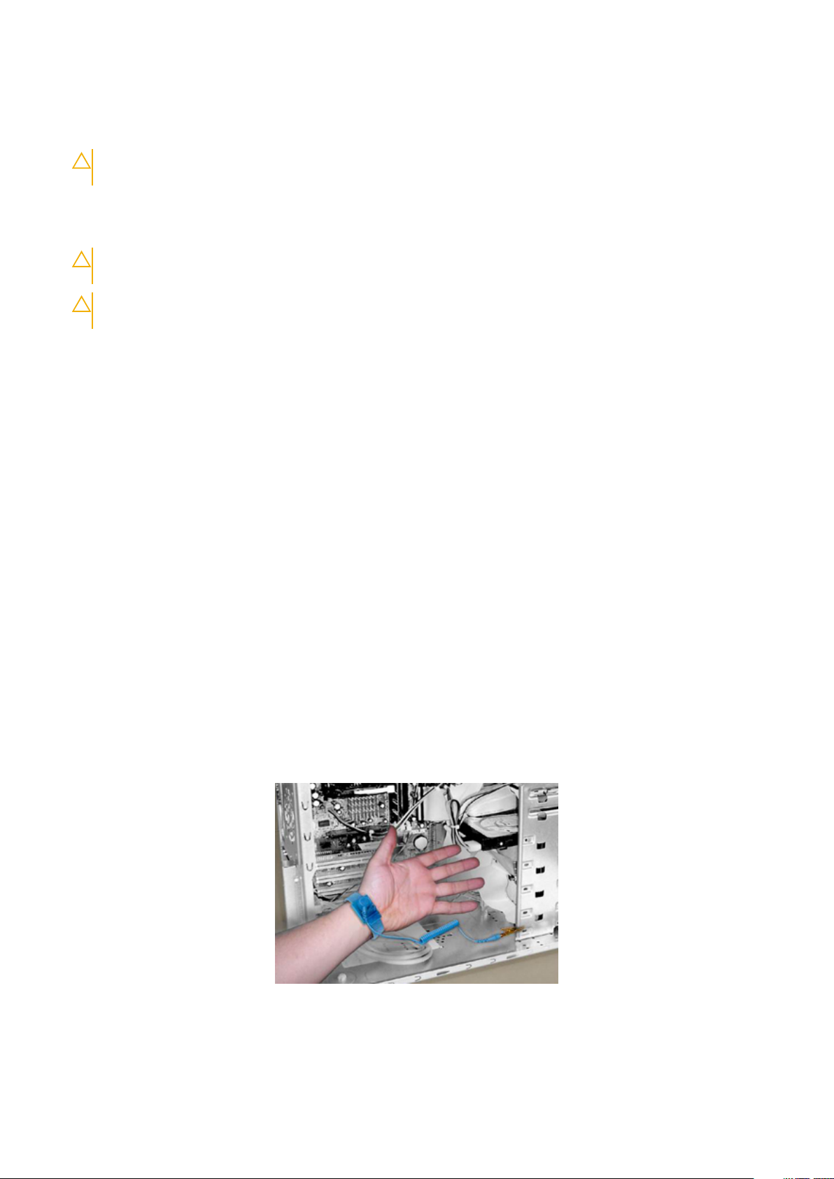
Bonding
Bonding is a method for connecting two or more grounding conductors to the same electrical potential. This is done through the use of a
Field Service ESD kit. When connecting a bonding wire, always ensure that it is connected to bare metal and never to a painted or nonmetal surface. The wrist strap should be secure and in full contact with your skin, and be sure to always remove all jewelry such as
watches, bracelets, or rings prior to bonding yourself and the equipment.
Figure 1. Bonding Properly
Working on your computer
7
Page 8
Electrostatic Discharge Protection
ESD is a major concern when you handle electronic components, especially sensitive components such as expansion cards, processors,
memory DIMMs, and system boards. Very slight charges can damage circuits in ways that may not be obvious, such as intermittent
problems or a shortened product life span. As the industry pushes for lower power requirements and increased density, ESD protection is
an increasing concern.
Due to the increased density of semiconductors used in recent Dell products, the sensitivity to static damage is now higher than in earlier
Dell products. For this reason some previously approved methods of handling parts are no longer applicable.
There are two recognized types of ESD damage: catastrophic and intermittent failures.
• Catastrophic —The damage causes an immediate and complete loss of device functionality. An example of catastrophic failure is a
memory DIMM that has received a static shock and immediately generates a "No POST/No Video" symptom with a beep code
emitted for missing or nonfunctional memory.
NOTE: Catastrophic failures represent approximately 20 percent of ESD-related failures.
• Intermittent —The DIMM receives a static shock, but the tracing is merely weakened and does not immediately produce outward
symptoms related to the damage. The weakened trace may take weeks or months to melt, and in the meantime may cause
degradation of memory integrity, intermittent memory errors, etc.
NOTE: Intermittent failures represent approximately 80 percent of ESD-related failures. The high rate of
intermittent failures means that most of the time when damage occurs, it is not immediately recognizable.
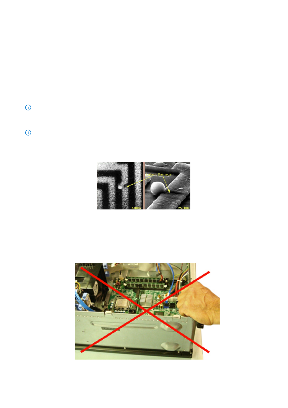
The more difficult type of damage to recognize and troubleshoot is the intermittent (also called latent or “walking wounded”) failure. The
following image shows an example of intermittent damage to a memory DIMM trace. Although the damage is done, the symptoms may
not become an issue or cause permanent failure symptoms for some time after the damage occurs.
Figure 2. Intermittent (Latent) Damage to a Wiring Trace
Do the following to prevent ESD damage:
• Use a wired ESD wrist strap that is properly grounded.
The use of wireless anti-static straps is no longer allowed; they do not provide adequate protection.
Touching the chassis before handling parts does not ensure adequate ESD protection on parts with increased sensitivity to ESD
damage.
Figure 3. Chassis "Bare Metal" Grounding (Unacceptable)
8
Working on your computer
Page 9
• Handle all static-sensitive components in a static-safe area. If possible, use anti-static floor pads and workbench pads.
• When handling static-sensitive components, grasp them by the sides, not the top. Avoid touching pins and circuit boards.
• When unpacking a static-sensitive component from its shipping carton, do not remove the component from the anti-static packing
material until you are ready to install the component. Before unwrapping the anti-static packaging, be sure to discharge static
electricity from your body.
• Before transporting a static-sensitive component, place it in an anti-static container or packaging.
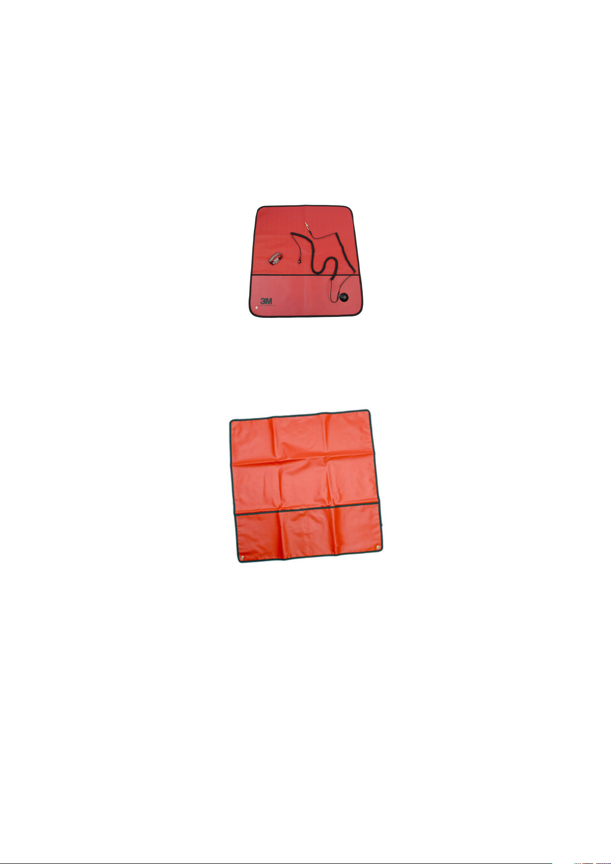
The ESD Field Service Kit
The unmonitored Field Service kit is the most commonly used. Each Field Service kit includes three main components: anti-static mat,
wrist strap, and bonding wire.
Figure 4. ESD Field Service Kit
The anti-static mat is dissipative and should be used to safely place parts on during service procedures. When using an anti-static mat,
your wrist strap should be snug and the bonding wire should be connected to the mat and to bare-metal on the system being worked on.
Once deployed properly, service parts can be removed from the ESD bag and placed directly on the mat. Remember, the only safe place
for ESD-sensitive items are in your hand, on the ESD mat, in the system, or inside a bag.
Figure 5. Anti-Static Mat
The wrist strap and bonding wire can be either directly connected between your wrist and bare metal on the hardware if the ESD mat is
not required, or connected to the anti-static mat to protect hardware that is temporarily placed on the mat. The physical connection of
the wrist strap and bonding wire between your skin, the ESD mat, and the hardware is known as bonding. Use only Field Service kits with
a wrist strap, mat, and bonding wire. Never use wireless wrist straps.
Always be aware that the internal wires of a wrist strap are prone to damage from normal wear and tear, and must be checked regularly
with a wrist strap tester in order to avoid accidental ESD hardware damage. It is recommended to test the wrist strap and bonding wire a
minimum of once per week.
Working on your computer
9
Page 10
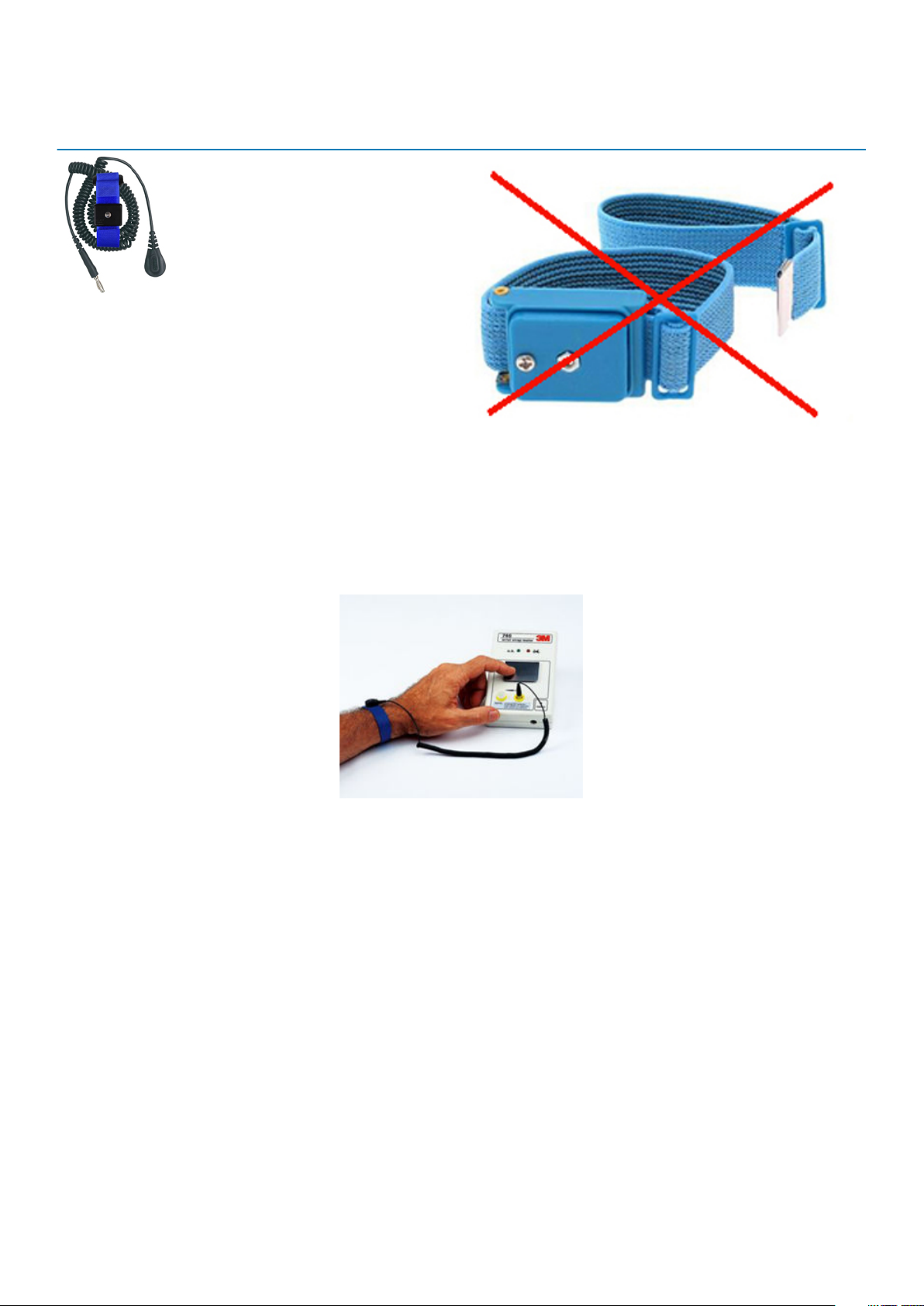
Table 1. Wrist Straps
Wrist Strap and Bonding Wire Wireless ESD Strap (Unacceptable)
ESD Wrist Strap Tester
The wires inside of an ESD strap are prone to damage over time. When using an unmonitored kit, it is best practice to regularly test the
strap prior to each service call, and at a minimum, test once per week. A wrist strap tester is the best method for doing this test. If you do
not have your own wrist strap tester, check with your regional office to find out if they have one. To perform the test, plug the wriststrap’s bonding-wire into the tester while it is strapped to your wrist and push the button to test. A green LED is lit if the test is
successful; a red LED is lit and an alarm sounds if the test fails.
Figure 6. Wrist Strap Tester
Insulator Elements
It is critical to keep ESD sensitive devices, such as plastic heat sink casings, away from internal parts that are insulators and often highly
charged.
10
Working on your computer
Page 11
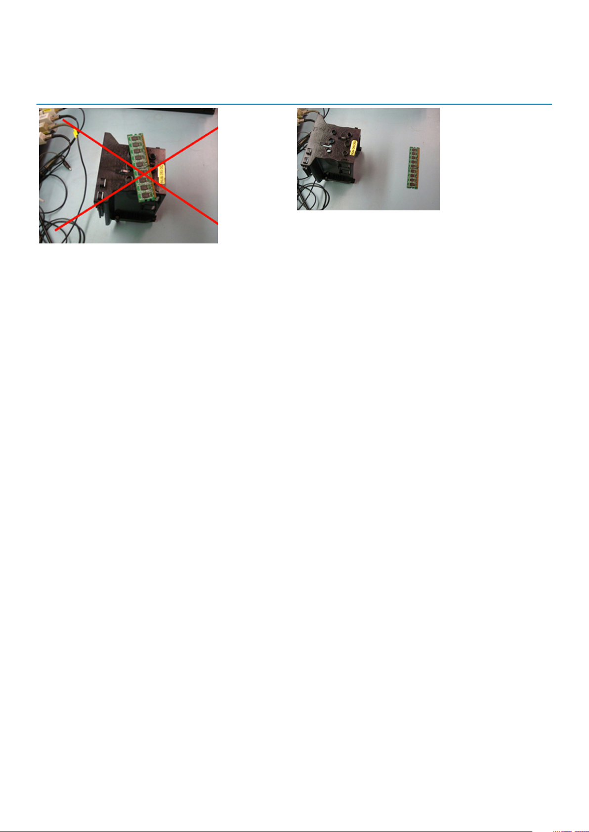
Table 2. Placement of Insulator Elements
Unacceptable — DIMM lying on an insulator part (plastic
heat sink shroud)
Acceptable — DIMM separated from the insulator part
Consider the Working Environment
Before deploying the ESD Field Service kit, assess the situation at the customer location. For example, deploying the kit for a server
environment is different than for a desktop or portable environment. Servers are typically installed in a rack within a data center; desktops
or portables are typically placed on office desks or cubicles.
Always look for a large open flat work area that is free of clutter and large enough to deploy the ESD kit with additional space to
accommodate the type of system that is being repaired. The workspace should also be free of insulators that can cause an ESD event. On
the work area, insulators such as Styrofoam and other plastics should always be moved at least 12 inches or 30 centimeters away from
sensitive parts before physically handling any hardware components.
ESD Packaging
All ESD-sensitive devices must be shipped and received in static-safe packaging. Metal, static-shielded bags are preferred. However, you
should always return the damaged part using the same ESD bag and packaging that the new part arrived in. The ESD bag should be folded
over and taped shut and all the same foam packing material should be used in the original box that the new part arrived in.
ESD-sensitive devices should be removed from packaging only at an ESD-protected work surface, and parts should never be placed on
top of the ESD bag because only the inside of the bag is shielded. Always place parts in your hand, on the ESD mat, in the system, or
inside an anti-static bag.
Working on your computer
11
Page 12
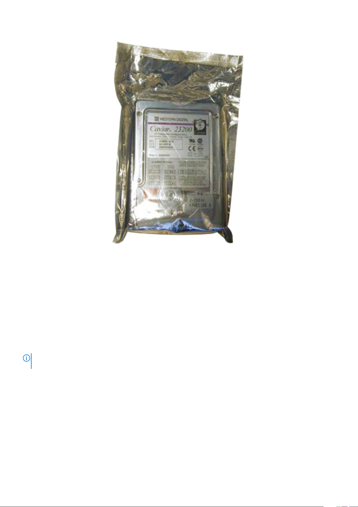
Figure 7. ESD Packaging
Transporting Sensitive Components
When transporting ESD-sensitive components such as replacement parts or parts to be returned to Dell, it is critical to place these parts in
anti-static bags for safe transport.
ESD Protection Summary
It is strongly suggested that all field service engineers use the traditional wired ESD grounding wrist strap and protective anti-static mat at
all times when servicing Dell products. In addition, it is critical that engineers keep sensitive parts separate from all insulator parts while
performing service and that they use anti-static bags for transporting sensitive components.
Lifting Equipment
NOTE:
Do not lift greater than 50 pounds. Always obtain assistance from another person or persons, or use a
mechanical lifting device.
Adhere to the following guidelines when lifting equipment:
1. Get a firm balanced footing. Keep your feet apart for a stable base, and point your toes out.
2. Bend your knees. Do not bend at the waist.
3. Tighten stomach muscles. Abdominal muscles support your spine when you lift, offsetting the force of the load.
4. Lift with your legs, not your back.
5. Keep the load close. The closer it is to your spine, the less force it exerts on your back.
6. Keep your back upright, whether lifting or setting down the load. Do not add the weight of your body to the load. Avoid twisting your
body and back.
7. Follow the same techniques in reverse to set the load down.
12
Working on your computer
Page 13

After working inside your computer
After you complete any replacement procedure, ensure that you connect external devices, cards, and cables before turning on your
computer.
CAUTION: To avoid damage to the computer, use only the battery designed for this particular Dell computer. Do not use
batteries designed for other Dell computers.
1. Connect any external devices, such as a port replicator or media base, and replace any cards, such as an ExpressCard.
2. Connect any telephone or network cables to your computer.
CAUTION: To connect a network cable, first plug the cable into the network device and then plug it into the
computer.
3. Connect your computer and all attached devices to their electrical outlets.
4. Turn on your computer.
Working on your computer 13
Page 14

2
Technology and components
This chapter details the technology and components available in the system.
Topics:
• UEFI BIOS
• DDR4
• Graphics options
• Supported hard drives
• HDMI 1.4a
• Battery Specifications
• USB features
• USB Type-C
• Media Card Readers
• Downloading Windows drivers
• Turning off your computer
UEFI BIOS
UEFI is an acronym for Unified Extensible Firmware Interface. The UEFI specification defines a new model for the interface between
personal computer operating systems and platform firmware. The interface consists of data tables that contain platform related
information, plus boot and runtime service calls that are available to the operating system and its loader. Together, these provide a
standard environment for booting an operating system and running pre-boot applications. One of the main differences between BIOS and
UEFI is the way applications are coded. Assembler was used if functions or applications had to be coded for the BIOS while a higher level
language code will be used to program the UEFI.
Dell UEFI BIOS implementation will supersede the existing two different sets of BIOS in the portables and desktop products into one single
UEFI BIOS moving forward.
Important Information
There is no difference in between the conventional BIOS and the UEFI BIOS unless the UEFI option is checked in the 'Boot List Option'
setting in the BIOS page. This will allow the user to create a UEFI boot option list manually without affecting the existing boot priority list.
With the implementation of UEFI BIOS, the changes are more related to the manufacturing tools and functionalities with very minimal
impact to the customer's usages.
A few things to remember are:
• If customers have a UEFI boot media, and ONLY if they have UEFI boot media (either in the optical media or via USB storage), the
one-time boot menu will show an additional section listing the UEFI boot options. Customers can view this option If they have UEFI
boot media attached, and the UEFI boot option is specified manually through the 'Boot Sequence' settings.
How to change Service Tag/Owner Tag?
When the service technician replaces a system board, it's required to set the service tag when the system restarts. Failure to set a service
tag may result in system battery not being able to charge. Therefore, it is very important that the service technician set the correct
system service tag. If a wrong service tag is set, then the technician will have to place the order for another system board replacement.
How to change Asset tag information?
To change the Asset tag information, we can use one of the following software utilities:
• Portables Technology Dell Command Configure toolkit-
14 Technology and components
Page 15
Customers may also report that after a motherboard replacement, the asset field is already populated in the system BIOS, and needs
to be cleared or set. For older systems and all newer systems with the UEFI BIOS platform, customers can download the Dell
Command Configure Toolkit (DCC) to customize the BIOS options or even change the ownership or asset tag from within Windows.
DDR4
DDR4 (Double Data Rate fourth generation) memory is a higher-speed successor to the DDR2 and DDR3 technologies and allows up to
512 GB in capacity, compared to the DDR3's maximum of 128 GB per DIMM. DDR4 synchronous dynamic random-access memory is
keyed differently from both SDRAM and DDR to prevent the user from installing the wrong type of memory into the system.
DDR4 needs 20 percent less or just 1.2 volts, compared to DDR3 which requires 1.5 volts of electrical power to operate. DDR4 also
supports a new, deep power-down mode that allows the host device to go into standby without needing to refresh its memory. Deep
power-down mode is expected to reduce standby power consumption by 40 to 50 percent.
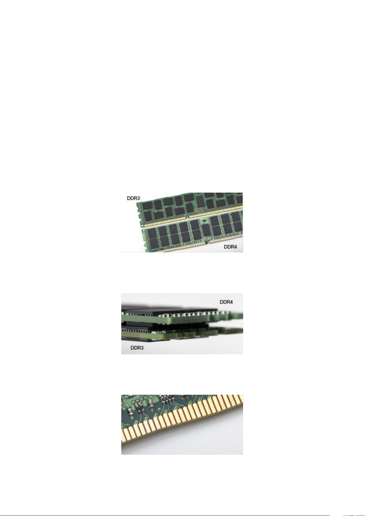
DDR4 Details
There are subtle differences between DDR3 and DDR4 memory modules, as listed below:
Key notch difference
The key notch on a DDR4 module is in a different location from the key notch on a DDR3 module. Both notches are on the insertion edge
but the notch location on the DDR4 is slightly different, to prevent the module from being installed into an incompatible board or platform.
Figure 8. Notch difference
Increased thickness
DDR4 modules are slightly thicker than DDR3, to accommodate more signal layers.
Figure 9. Thickness difference
Curved edge
DDR4 modules feature a curved edge to help with insertion and alleviate stress on the PCB during memory installation.
Figure 10. Curved edge
Technology and components
15
Page 16

Memory Errors
Memory errors on the system display the new 2 - Amber, 3 - White failure code. If all memory fails, the LCD does not turn on.
Troubleshoot for possible memory failure by trying known good memory modules in the memory connectors on the bottom of the system
or under the keyboard, as in some portable systems.
Graphics options
Integrated graphics controller
Table 3. Graphics specification
Integrated graphics controller specifications
Integrated Graphics Controller Intel UHD Graphics
Model Dell Latitude 3310
Bus Type
Memory Interface
Basic Graphic frequency Pentium 5405 U: 300 Mhz
Max Graphics dynamic frequency Pentium 5405 U: 950 Mhz
Graphics Level Intel Celeron 4205 U: Intel UHD Graphic 610
Estimated Maximum Power Consumption
(TDP)
Display Support eDP (internal), HDMI, DisplayPort through Type-C port
Internal Interface
Unified Memory Architecture
Celeron 4205 U: 300 Mhz
i3-8145 U: 300 Mhz
i5-8265 U: 300 Mhz
Celeron 4205 U: 900 Mhz
i3-8145 U: 1.00 GHz
i5-8265 U: 1.1 GHz
Intel Pentium 5405 U: Intel UHD Graphic 610
i3-8145 U: Intel UHD Graphic 620
i5-8265 U: Intel UHD Graphic 620
15 W (Total SOC power consumption)
Maximum Color Depth 32 bit
Maximum Vertical Refresh Rate Up to 85 Hz depending on resolution
Operating Systems Graphics/ Video API
Support
Supported Resolutions and Max Refresh
Rates (Hz) (Note: Analog and/or digital)
Numbers of Displays Supported 3 max
16 Technology and components
DirectX 12, OpenGL 4.5
eDP: Panel 1366 x 768 @ 60 Hz
HDMI: V1.4 @1.65 Gbps
DisplayPort (via Type-C): V1.2 (Except Celeron sku)
Page 17

Supported hard drives
128/256 GB M.2 2230 PCIe SSD (Class 35)
Table 4. 128/256 GB M.2 2230 PCIe SSD (Class 35)
Specifications
Capacity (GB) 128 GB/256 GB
Dimensions (W x D x H) 22 x 30 x 2.38 (mm)
Interface type and maximum speed PCIe Gen 3 8 Gbps (up to 2 lanes)
MTBF 1.4 Mil hours
Logical blocks 250,069,680
Power source
Power consumption (reference only) Idle 0.05 W, Active 4.5 W
Environmental Operating Conditions (Non-Condensing)
Temperature range 0 °C to 70 °C
Relative humidity range 10% to 90%
Op shock (@ 2ms) 1,500 G
Environmental Non-Operating Conditions (Non-Condensing)
Temperature range - 40 °C to 70 °C
Relative humidity range 5% to 95%
64 GB eMMC 5.1 SSD
Table 5. 64 GB eMMC 5.0 SSD specifications
Specifications
Capacity (GB) 64 GB
Dimensions (W x D x H) 0.86 x 1.65 x 0.05 (inch)
Interface type and maximum speed Upto eMMC 5.1, HS200, 200 Mbps
MTBF 1.4 Mil hours
Logical blocks 500,118,192
Power source
Power consumption (reference only) Idle 0.05 W, Active 4.5 W
Environmental Operating Conditions (Non-Condensing)
Temperature range 0 °C to 70 °C
Relative humidity range 5% to 95%
Technology and components 17
Page 18

Specifications
Environmental Non-Operating Conditions (Non-Condensing)
Temperature range - 40 °C to 70 °C
Relative humidity range 5% to 95%
HDMI 1.4a
This topic explains the HDMI 1.4a and its features along with the advantages.
HDMI (High-Definition Multimedia Interface) is an industry-supported, uncompressed, all-digital audio/video interface. HDMI provides an
interface between any compatible digital audio/video source, such as a DVD player, or A/V receiver and a compatible digital audio and/or
video monitor, such as a digital TV (DTV). The primary advantage is cable reduction and content protection provisions. HDMI supports
standard, enhanced, or high-definition video, plus multichannel digital audio on a single cable.
HDMI 1.4a Features
• HDMI Ethernet Channel - Adds high-speed networking to an HDMI link, allowing users to take full advantage of their IP-enabled
devices without a separate Ethernet cable.
• Audio Return Channel - Allows an HDMI-connected TV with a built-in tuner to send audio data "upstream" to a surround audio
system, eliminating the need for a separate audio cable.
• 3D - Defines input/output protocols for major 3D video formats, paving the way for true 3D gaming and 3D home theater applications.
• Content Type - Real-time signaling of content types between display and source devices, enabling a TV to optimize picture settings
based on content type.
• Additional Color Spaces - Adds support for additional color models used in digital photography and computer graphics.
• 4K Support - Enables video resolutions far beyond 1080p, supporting next-generation displays that will rival the Digital Cinema
systems used in many commercial movie theaters.
• HDMI Micro Connector - A new, smaller connector for phones and other portable devices, supporting video resolutions up to 1080p.
• Automotive Connection System - New cables and connectors for automotive video systems, designed to meet the unique
demands of the motoring environment while delivering true HD quality.
Advantages of HDMI
• Quality HDMI transfers uncompressed digital audio and video for the highest, crispest image quality.
• Low-cost HDMI provides the quality and functionality of a digital interface while also supporting uncompressed video formats in a
simple, cost-effective manner.
• Audio HDMI supports multiple audio formats from standard stereo to multichannel surround sound.
• HDMI combines video and multichannel audio into a single cable, eliminating the cost, complexity, and confusion of multiple cables
currently used in A/V systems.
• HDMI supports communication between the video source (such as a DVD player) and the DTV, enabling new functionality.
Battery Specifications
What is ExpressCharge ?
For a system advertised as having the ExpressCharge feature, the battery typically will have greater than 80% charge after about an hour
of charging with the system off and fully charged in about 2 hours with the system off.
Enabling Expresscharge requires that both the system and the battery that is used on the system be ExpressCharge capable. If any of the
above requirements is missing, ExpressCharge will not be enabled.
What is BATTMAN?
BATTMAN is a computer controlled battery manager intended for typical rechargeable batteries. It has the following capabilities:
• Monitors self-discharge
18
Technology and components
Page 19

• Measures internal resistance
• Automatically performs repeated discharge/charge cycles to break in new batteries
• Keeps a log of all operations performed, which can be imported
• Connects via parallel port to any PC running Microsoft Windows
• Operating software, complete with source code, is available to download
USB features
Universal Serial Bus, or USB, was introduced in 1996. It dramatically simplified the connection between host computers and peripheral
devices like mice, keyboards, external drivers, and printers.
Table 6. USB evolution
Type Data Transfer Rate Category Introduction Year
USB 2.0 480 Mbps High Speed 2000
USB 3.0/USB 3.1 Gen 1
Port
USB 3.1 Gen 2 10 Gbps SuperSpeed 2013
USB 3.0/USB 3.1 Gen 1 (SuperSpeed USB)
For years, the USB 2.0 has been firmly entrenched as the de facto interface standard in the PC world with about 6 billion devices sold, and
yet the need for more speed grows by ever faster computing hardware and ever greater bandwidth demands. The USB 3.0/USB 3.1 Gen 1
finally has the answer to the consumers' demands with a theoretically 10 times faster than its predecessor. In a nutshell, USB 3.1 Gen 1
features are as follows:
• Higher transfer rates (up to 5 Gbps)
• Increased maximum bus power and increased device current draw to better accommodate power-hungry devices
• New power management features
• Full-duplex data transfers and support for new transfer types
• Backward USB 2.0 compatibility
• New connectors and cable
The topics below cover some of the most commonly asked questions regarding USB 3.0/USB 3.1 Gen 1.
5 Gbps SuperSpeed 2010
Speed
Currently, there are 3 speed modes defined by the latest USB 3.0/USB 3.1 Gen 1 specification. They are Super-Speed, Hi-Speed and FullSpeed. The new SuperSpeed mode has a transfer rate of 4.8 Gbps. While the specification retains Hi-Speed, and Full-Speed USB mode,
commonly known as USB 2.0 and 1.1 respectively, the slower modes still operate at 480 Mbps and 12 Mbps respectively and are kept to
maintain backward compatibility.
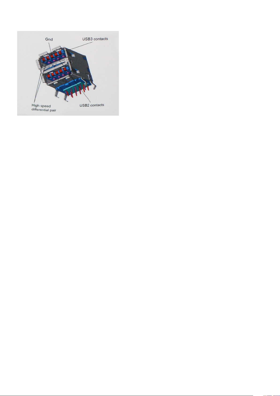
USB 3.0/USB 3.1 Gen 1 achieves the much higher performance by the technical changes below:
• An additional physical bus that is added in parallel with the existing USB 2.0 bus (refer to the picture below).
• USB 2.0 previously had four wires (power, ground, and a pair for differential data); USB 3.0/USB 3.1 Gen 1 adds four more for two
pairs of differential signals (receive and transmit) for a combined total of eight connections in the connectors and cabling.
• USB 3.0/USB 3.1 Gen 1 utilizes the bidirectional data interface, rather than USB 2.0's half-duplex arrangement. This gives a 10-fold
increase in theoretical bandwidth.
Technology and components
19
Page 20
With today's ever increasing demands placed on data transfers with high-definition video content, terabyte storage devices, high
megapixel count digital cameras etc., USB 2.0 may not be fast enough. Furthermore, no USB 2.0 connection could ever come close to the
480Mbps theoretical maximum throughput, making data transfer at around 320 Mbps (40 MB/s) — the actual real-world maximum.
Similarly, USB 3.0/USB 3.1 Gen 1 connections will never achieve 4.8Gbps. We will likely see a real-world maximum rate of 400MB/s with
overheads. At this speed, USB 3.0/USB 3.1 Gen 1 is a 10x improvement over USB 2.0.
Applications
USB 3.0/USB 3.1 Gen 1 opens up the laneways and provides more headroom for devices to deliver a better overall experience. Where USB
video was barely tolerable previously (both from a maximum resolution, latency, and video compression perspective), it's easy to imagine
that with 5-10 times the bandwidth available, USB video solutions should work that much better. Single-link DVI requires almost 2Gbps
throughput. Where 480Mbps was limiting, 5Gbps is more than promising. With its promised 4.8Gbps speed, the standard will find its way
into some products that previously weren't USB territory, like external RAID storage systems.
Listed below are some of the available SuperSpeed USB 3.0/USB 3.1 Gen 1 products:
• External Desktop USB 3.0/USB 3.1 Gen 1 Hard Drives
• Portable USB 3.0/USB 3.1 Gen 1 Hard Drives
• USB 3.0/USB 3.1 Gen 1 Drive Docks & Adapters
• USB 3.0/USB 3.1 Gen 1 Flash Drives & Readers
• USB 3.0/USB 3.1 Gen 1 Solid-state Drives
• USB 3.0/USB 3.1 Gen 1 RAIDs
• Optical Media Drives
• Multimedia Devices
• Networking
• USB 3.0/USB 3.1 Gen 1 Adapter Cards & Hubs
Compatibility
The good news is that USB 3.0/USB 3.1 Gen 1 has been carefully planned from the start to peacefully co-exist with USB 2.0. First of all,
while USB 3.0/USB 3.1 Gen 1 specifies new physical connections and thus new cables to take advantage of the higher speed capability of
the new protocol, the connector itself remains the same rectangular shape with the four USB 2.0 contacts in the exact same location as
before. Five new connections to carry receive and transmitted data independently are present on USB 3.0/USB 3.1 Gen 1 cables and only
come into contact when connected to a proper SuperSpeed USB connection.
USB Type-C
USB Type-C is a new, tiny physical connector. The connector itself can support various exciting new USB standards like USB 3.1 and USB
power delivery (USB PD).
20
Technology and components
Page 21

Alternate Mode
USB Type-C is a new connector standard that is very small. It is about a third the size of an old USB Type-A plug. This is a single
connector standard that every device should be able to use. USB Type-C ports can support a variety of different protocols using
“alternate modes,” which allows you to have adapters that can output HDMI, VGA, DisplayPort, or other types of connections from that
single USB port
USB Power Delivery
The USB PD specification is also closely intertwined with USB Type-C. Currently, smartphones, tablets, and other mobile devices often
use a USB connection to charge. A USB 2.0 connection provides up to 2.5 watts of power — that'll charge your phone, but that's about
it. A laptop might require up to 60 watts, for example. The USB Power Delivery specification ups this power delivery to 100 watts. It's bidirectional, so a device can either send or receive power. And this power can be transferred at the same time the device is transmitting
data across the connection.
This could spell the end of all those proprietary laptop charging cables, with everything charging via a standard USB connection. You could
charge your laptop from one of those portable battery packs you charge your smartphones and other portable devices from today. You
could plug your laptop into an external display connected to a power cable, and that external display would charge your laptop as you used
it as an external display — all via the one little USB Type-C connection. To use this, the device and the cable have to support USB Power
Delivery. Just having a USB Type-C connection doesn't necessarily mean they do.
USB Type-C and USB 3.1
USB 3.1 is a new USB standard. USB 3's theoretical bandwidth is 5 Gbps, while USB 3.1's is 10 Gbps. That's double the bandwidth, as fast
as a first-generation Thunderbolt connector. USB Type-C isn't the same thing as USB 3.1. USB Type-C is just a connector shape, and the
underlying technology could just be USB 2 or USB 3.0. In fact, Nokia's N1 Android tablet uses a USB Type-C connector, but underneath
it's all USB 2.0 — not even USB 3.0. However, these technologies are closely related.
Media Card Readers
NOTE:
The media card reader is integrated into the system board on portable systems. If there is a hardware failure or
the reader malfunctions, replace the system board.
The media card reader expands the usefulness and functionality of portable systems, especially when used with other devices such as
digital cameras, portable MP3 players, and handheld devices. All these devices use a form of media card to store information. Media card
readers allows for easy transfer of data between these devices.
Several different types of media or memory cards are available today. Below is a list of the different types of cards that work in the media
card reader.
SD Card Reader
1. Memory Stick
2. Secure Digital (SD)
3. Secure Digital High Capacity (SDHC)
4. Secure Digital eXtended Capacity(SDXC)
Technology and components
21
Page 22

Downloading Windows drivers
1. Turn on the laptop.
2. Go to Dell.com/support.
3. Click Product Support, enter the Service Tag, and then click Submit.
NOTE: If you do not have the Service Tag, use the auto detect feature or manually browse for your laptop model.
4. Click Drivers and Downloads.
5. Select the operating system installed on your laptop.
6. Scroll down the page and select the driver to install.
7. Click Download File to download the driver.
8. After the download is complete, navigate to the folder where you saved the driver file.
9. Double-click the driver file icon and follow the instructions on the screen.
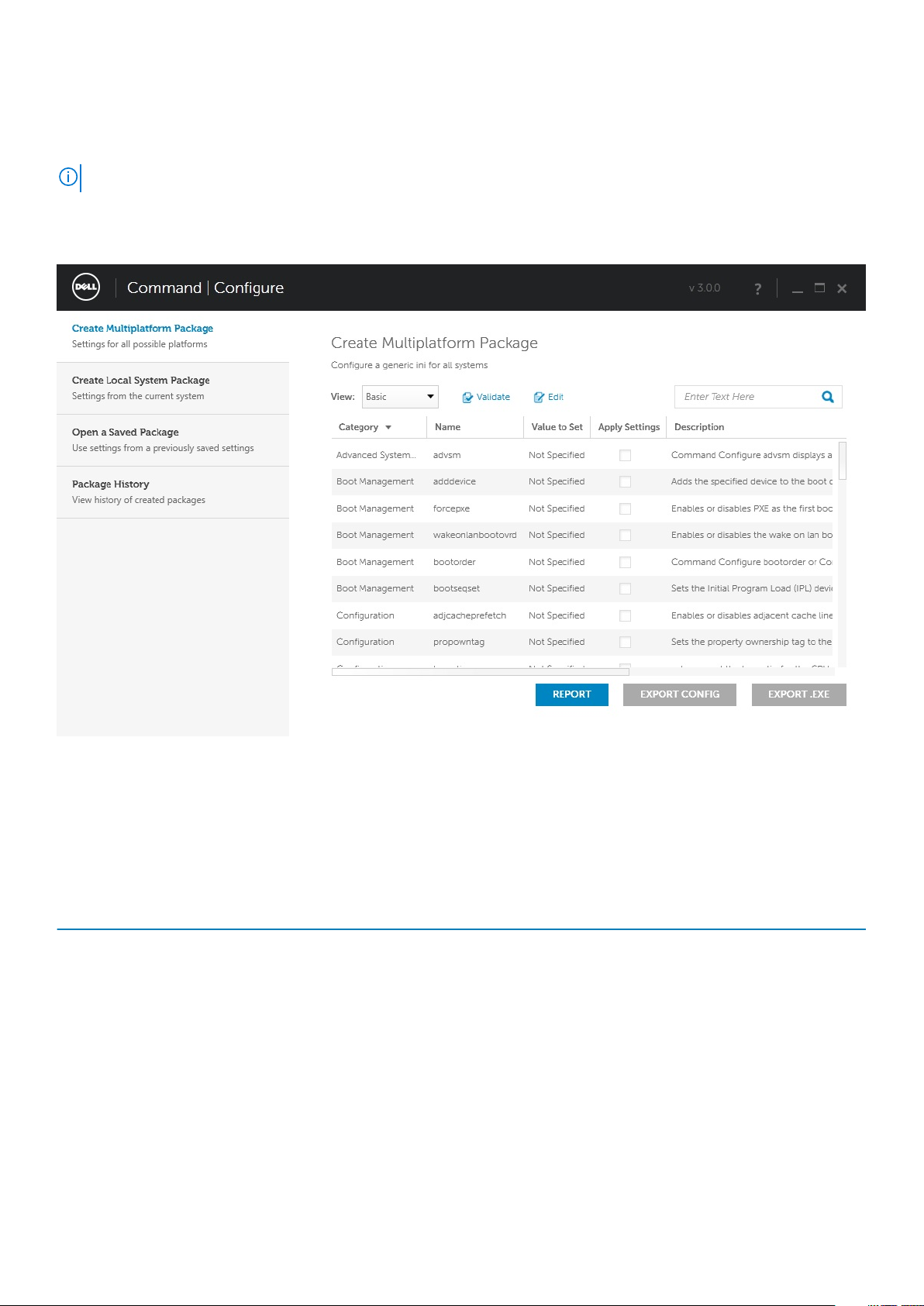
Dell Command Configure
Dell Command | Configure (Command | Configure) is a packaged software offering that provides configuration capability to business
client platforms. This product consists of a Command Line Interface (CLI) and Graphical User Interface (GUI) to configure various BIOS
features. You can use Command | Configure on Microsoft Windows Pre-installation Environment (Windows PE), Windows 7, Windows 8,
and Windows 8.1, Windows 10 operating systems, and Red Hat Enterprise Linux environments.
What’s new with Dell Command | Configure
The new features for the Dell Command | Configure includes:
• Dell Client Configuration Toolkit (CCTK) is re-branded as Dell Command | Configure (DCC).
• New User Interface.
• Support for Red Hat Enterprise Linux 7.0 Client version (64-bit) operating system.
• Support for x6 client platforms
• Support for Advanced System Management (ASM) 2.0 on Dell Precision™ Workstations for setting the non-critical upper threshold
values for cooling probes.
• Support for additional arguments: medium_high and medium_low for configuring the fan speed using --fanspeed option.
• Support for the following BIOS options:
• --backcamera.
• --fnlock
• --fnlockmode
• --gpsradio
• --keyboardbacklightonacpower
• --rearusb
• --sideusb
• --unmanagednic
Platforms Supported
These are the business clients platforms supported:
• Latitude
• OptiPlex
• Dell Precision Workstation Mobile
• Dell Precision Workstation
™
™
Dell Command | Configure will not be pre-loaded for the customer upon purchase. Customers will be able to
NOTE:
download the software from the Dell support website.
Command | Configure Graphical User Interface
The Dell Command | Configure Graphical User Interface (Command | Configure GUI) displays all Basic Input/Output System (BIOS)
configurations supported by Command | Configure. Using the GUI, you can perform the following tasks:
22
Technology and components
Page 23
• Create BIOS configuration for client systems
• Validate the BIOS configuration against the BIOS configuration of the host system
• Export the customized BIOS configurations as a configuration file (.ini/.cctk), Self-Contained Executable (SCE), shell script, or report
NOTE: To apply the configuration using Command Line Interface (CLI), run the required file (.ini , .cctk, or sce).
Accessing Command | Configure From a Windows System
Click Start > All Programs > Dell > Command | Configure > Command Configure Command Wizard.
Accessing Command | Configure From a Linux System
Navigate to the /opt/Dell/toolkit/bin directory.
Files And Folders of Command | Configure
The following table displays the files and folders of Command | Configure on a Windows system.
Table 7. Files And Folders configuration
Files/Folders Description
Command | Configure Command
Prompt
Configuration Wizard Allows access to the Command | Configure GUI.
Command | Configure WINPE Allows access to the Windows PE scripts to create a bootable image. For more details, see the Dell
Uninstall Uninstalls Command | Configure.
User’s Guide Online Provides access to the Command | Configure online documentation.
Allows access to the Command | Configure command prompt.
Command | Configure Installation Guide.
Technology and components 23
Page 24
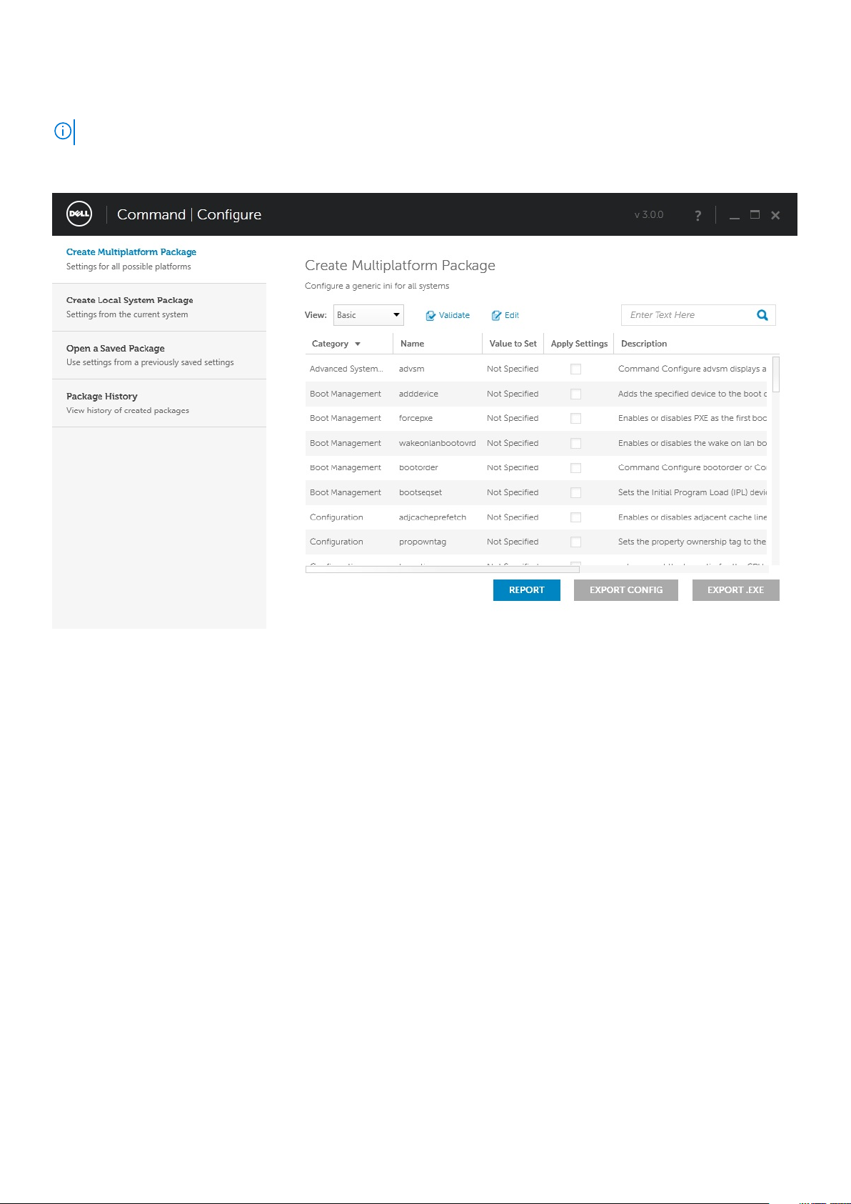
Launching The Command | Configure GUI
NOTE: The Command | Configure GUI is supported only on systems running the Windows operating system.
To launch the GUI, click Start > All Programs > Dell > Command Configure > Configuration Wizard or double-click the Dell
Configuration Wizard on the desktop. The below screen appears:
Command Line Interface
This chapter provides a general overview of the Command Line Interface (CLI) utility. It explains how to run the commands and the syntax
details of the command line options used to configure BIOS settings for the client systems.
Running Command | Configure Commands
You can run the Command | Configure commands in two ways:
• Using Command Prompt
• Using Bootable Image
Command Prompt
To run Command | Configure commands:
1. Click Start → All Program → Dell → Command Configure → Command Configure Command Prompt.
2. Navigate to the x86 or x86_64 directory depending on the architecture of the operating system.
3. Run the Command | Configure commands.
Bootable Image
To run Command | Configure commands:
1. Copy Dell Command | Configure with the International Organization for Standardization (ISO) image to a Compact Disc (CD). For
more information, see Dell Command | Configure Installation Guide.
2. Boot the system that you want to configure from the CD.
3. Navigate to the Command Configure\x86 or Command Configure\x86_64 directory.
4. Run the Command | Configure commands.
24
Technology and components
Page 25

Turning off your computer
Turning off your computer—Windows
CAUTION: To avoid losing data, save and close all open files and exit all open programs before you turn off your
computer or remove the side cover.
1. Click or tap .
Click or tap
2.
and then click or tap Shut down.
NOTE: Ensure that the computer and all attached devices are turned off. If your computer and attached devices did
not automatically turn off when you shut down your operating system, press and hold the power button for about 6
seconds to turn them off.
Technology and components 25
Page 26

3
26 Major components of your system
Page 27
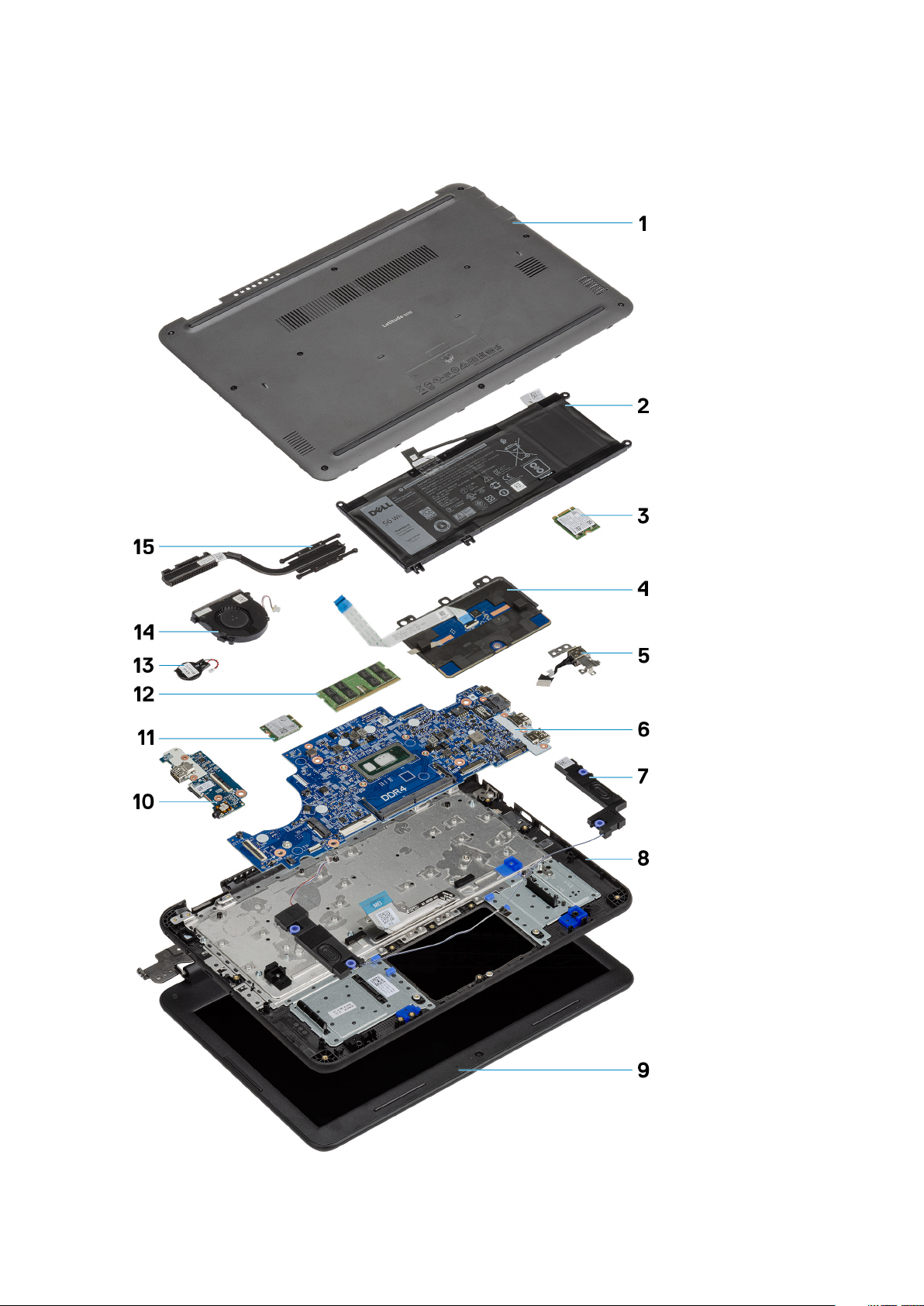
Major components of your system
Major components of your system 27
Page 28

1. Back cover
2. Battery
3. Solid state drive (SSD)
4. Touchpad
5. Dc-in
6. System board
7. Speakers
8. Palmrest
9. LCD
10. I/O board
11. WLAN
12. Memory
13. Coin cell
14. System fan
15. Heatsink
28 Major components of your system
Page 29

Disassembly and reassembly
Screw List
The following table shows the screw list and the images for Latitude 3310, for different components and locations.
Table 8. Screw Size List
Component Quantity Screw type Image
4
• System board to palmrest
• DC-In bracket
• LCD Panel to back cover
• Touchpad frame to palmrest
• SSD bracket to palmrest
• Battery retaining bracket
• Battery support bracket
• I/O Board to palmrest
• Fan to palmrest
Hinges to LCD back cover 6 M2.5 x 3.5
• Touchpad to palmrest
• I/O Daughter
• I/O Board to palmrest
Hinges to palmrest 5 M2.5 x 5.0
• LCD bezel to back cover
• DC-In bracket to MB
• I/O board to palmrest
• System board to palmrest
• SSD to SSD Bracket
• 2
• 1
• 4
• 3
• 2
• 2
• 1
• 1
• 2
• 3
• 1
• 1
• 2
• 1
• 1
• 1
• 1
M2.0 x 2.0
M2.0 x 3.0
M2.0 x 3.0 (large head)
M2.0 x 4.0
• Base cover to palmrest
• Heatsink to system board
• 10
• 4
M2.5 x 8.0 Captive screws (Part of the
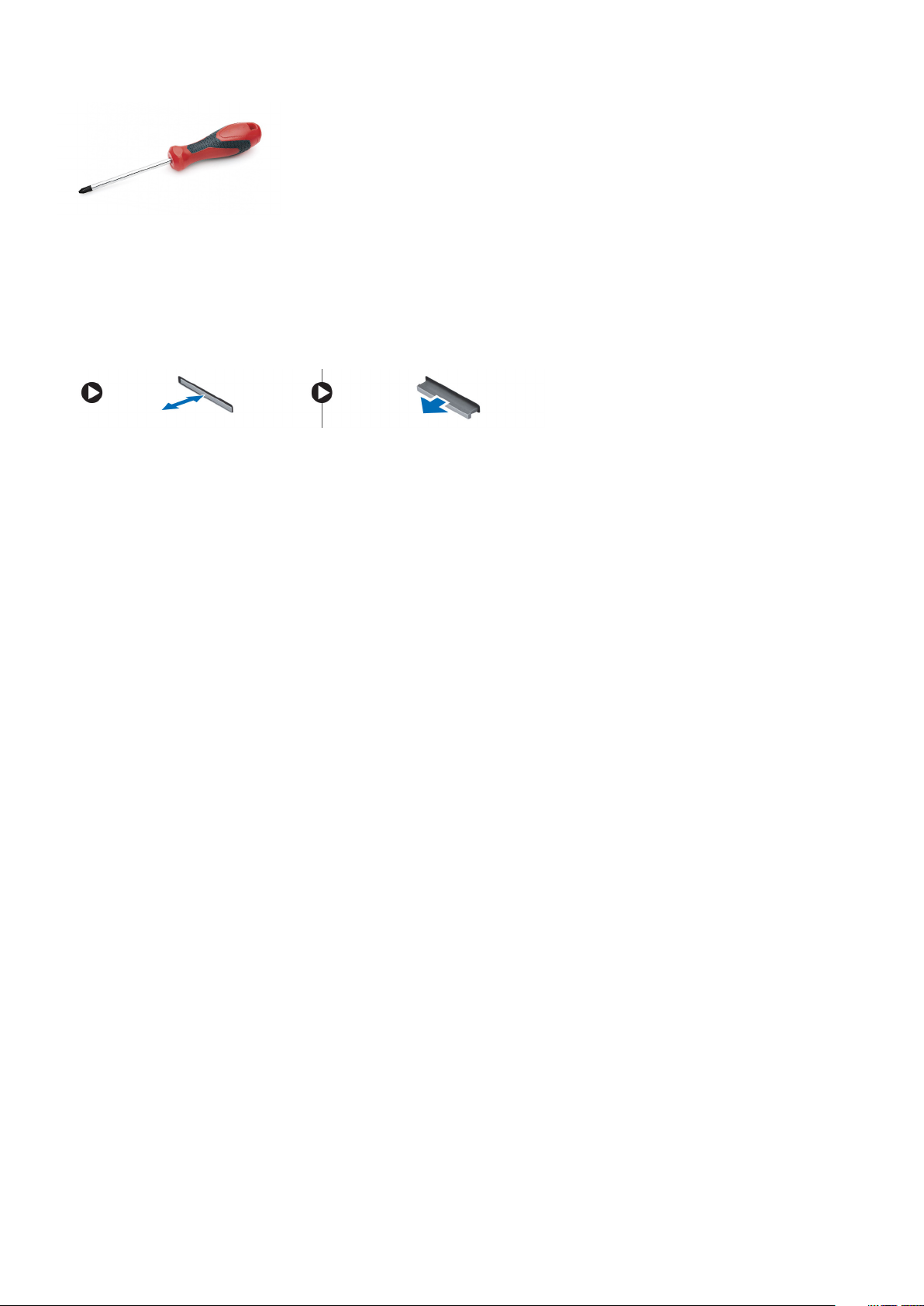
Recommended tools
The procedures in this document require the following tools:
• Phillips #0 screwdriver
• Phillips #1 screwdriver
• Plastic scribe
NOTE: The #0 screw driver is for screws 0-1 and the #1 screw driver is for screws 2-4.
base cover)
Disassembly and reassembly 29
Page 30
microSD card
Removing the microSD card
1. Press in on the microSD card to release it from the computer.
2. Remove the microSD card from the computer.
Installing the microSD card
Slide the microSD card into its slot until it clicks into place.
Base Cover
Removing the base cover
1. Follow the procedure in Before working inside your computer.
2. Remove the:
a) microSD card
3. Loosen the 10 'M2.5xL8.0' captive screws that secure the base cover to the computer.
30
Disassembly and reassembly
Page 31

4. Use a plastic scribe [1] and pry the base cover along the edges [2] to separate the base cover from the computer.
5. Lift the base cover up and away from the computer.
Disassembly and reassembly
31
Page 32

Installing the base cover
1. Align the base cover and place it on the computer.
32
Disassembly and reassembly
Page 33

2. Press down along the edges of the base cover until it clicks into place.
3. Tighten the 10 'M2.5xL8.0' captive screws to secure the base cover to the computer.
Disassembly and reassembly
33
Page 34

4. Install the:
a) microSD card
5. Follow the procedure in After working inside your computer.
Battery
Removing the battery
1. Follow the procedure in Before working inside your computer.
2. Remove the:
a) microSD card
b) base cover
3. Peel off the tape [1] and disconnect the battery cable from the system board [2].
4. Peel off the piece of tape [3] on the memory module bracket and unroute the battery cable.
34
Disassembly and reassembly
Page 35

5. Remove the single M2.0x3.0 screw [1] and the battery retaining bracket [2].
NOTE:
This procedure shows a 3-cell 42 WHr battery removal. The 4-cell 56 WHr battery is slightly bigger in size and
attaches to the palmrest.
6. Remove the two M2.0x3.0 screws [3] and separate the battery support bracket [4] from the palmrest.
7. Lift the battery away from the computer.
Disassembly and reassembly
35
Page 36

8. Peel off the tape [1] and disconnect the battery cable from the battery [2].
Installing the battery
1. Install the battery cable on the battery [1] and secure it using a piece of tape [2].
36
Disassembly and reassembly
Page 37

2.
NOTE: This procedure illustrates a 3-cell 42 WHr battery, a 4-cell 56 WHr battery mounts is slightly bigger in size
and attaches to different mount points on the palmrest.
Insert the battery into the slot on the computer [1] and align the battery and the screw hole on the palmrest [2].
3. Install the battery support bracket [1] and install the two M2.0x3.0 screws securing the battery to the palmrest [2].
4. Install the battery [3] and the single M2.0x3.0 screw to retain the battery [4] to the palmrest.
Disassembly and reassembly
37
Page 38

5. Connect the battery cable to the system board [1] and secure it using a piece of tape [2].
6. Route the battery cable along the memory module bracket and secure it using a piece of tape [3].
7. Install the:
a) base cover
b) microSD card
38
Disassembly and reassembly
Page 39

8. Follow the procedure in After working inside your computer.
Coin Cell
Removing the coin cell
1. Follow the procedure in Before working inside your computer.
2. Remove the:
a) microSD card
b) base cover
c) battery
3.
4. Lift and remove the coin cell from the system [2].
CAUTION: Back up the data before removing the coin cell. Removal of the coin cell resets the BIOS and may cause
No Boot, No POST, or potential loss of data.
Disconnect the battery cable from its connector on the system board [1].
NOTE: A strong adhesive is used on the coin cell; a bit of force is needed to peel the battery from the palmrest.
Installing the coin cell
1. Place the coin cell battery into the system [1].
2. Connect the coin cell battery cable to its connector on the system board [2].
Disassembly and reassembly
39
Page 40

3. Install the:
a) battery
b) base cover
c) microSD card
4. Follow the procedure in After working inside your computer.
Memory Module
Removing the memory module
1. Follow the procedure in Before working inside your computer.
2. Remove the:
a) microSD card
b) base cover
c) battery
3. Pry apart the memory module latches [1].
4. Lift and remove the memory module from the system board [2].
40
Disassembly and reassembly
Page 41

Installing the memory module
1. Insert the memory module at an acute angle into its connector on the system board [1].
2. Gently push the memory module until the latches snap into place [2].
3. Install the:
a) battery
b) base cover
Disassembly and reassembly
41
Page 42

c) microSD card
4. Follow the procedure in After working inside your computer.
Solid state drive (SSD)
Removing the SSD
1.
2. Remove the:
3. Remove the single M2.0x4.0 screw along with the washer that secures the SSD on the extender [1].
4. Remove the SSD from the M.2 slot on the system board [2].
NOTE: This system has the option to fit two form factors (M.2 2242 and M.2 2230) SSD/eMMC cards. This is
achieved by removing, inverting, and installing the extender to an alternate location as marked on the palmrest.
Follow the procedure in Before working inside your computer.
a) microSD card
b) base cover
c) battery
Figure 11. M.2 2230 SSD
Installing the SSD
1. Install the SSD in the M.2 bracket [1] and secure it to the extender using the single M2.0x4.0 screw and washer [2].
42
Disassembly and reassembly
Page 43

Figure 12. M.2 2230 SSD
2. Install the:
a) battery
b) base cover
c) microSD card
3. Follow the procedure in After working inside your computer.
SSD bracket
Removing the SSD bracket
1.
2. Remove the:
3. Remove the two M2.0x3.0 screws securing the SSD bracket to the palmrest [1].
4. Remove the SSD bracket from the palmrest [2].
NOTE:
This system has the option to fit two form factors (M.2 2242 and M.2 2230) SSD/eMMC cards. This is
achieved by removing, inverting, and installing the extender to an alternate location as marked on the palmrest.
Follow the procedure in Before working inside your computer.
a) microSD card
b) base cover
c) battery
d) SSD
Disassembly and reassembly
43
Page 44

Figure 13. M.2 2230 SSD
Installing the SSD bracket
1. Install the SSD bracket in the palmrest [1].
2. Install the two M2.0x3.0 screws securing the SSD bracket to the palmrest [2].
Figure 14. M.2 2230 SSD
3. Install the:
44
Disassembly and reassembly
Page 45

a) SSD
b) battery
c) base cover
d) microSD card
4. Follow the procedure in After working inside your computer.
Keyboard
Removing the keyboard
1. Follow the procedure in Before working inside your computer.
2. Remove the:
a) microSD card
b) base cover
c) battery
3. Disconnect the keyboard cable from the system board [1].
4. Hold the sides of the palmrest securely while pushing into the two release holes using a plastic scribe [2].
NOTE: It takes some force to push out the keyboard through the two release holes. Exercise due caution.
5. Gently pry up the lower edge of the keyboard from the computer.
Disassembly and reassembly
45
Page 46

6. Gently remove the keyboard cable from underneath the keyboard.
46
Disassembly and reassembly
Page 47

NOTE: Unroute the keyboard cable from the touchpad bracket before proceeding.
7. Slide the keyboard towards the touchpad [1] and lift it up [2] to remove it from the computer.
Disassembly and reassembly
47
Page 48

Installing the keyboard
1. Install the keyboard on the computer [1] and slide it into the retention tabs in the holes on the palmrest [2].
NOTE: Keyboard cable must be inserted parallel to the connector.
NOTE: Remove the antiadhesive paper on the keyboard before inserting the cable.
NOTE: After the cable is inserted, the operator must hold the cable with the left and press the actuator down by the
right hand to avoid loosening the cable.
48 Disassembly and reassembly
Page 49

2. Tuck in the keyboard cable and route it along the touchpad bracket.
Disassembly and reassembly
49
Page 50

3. Press the keyboard until it clicks in place.
50
Disassembly and reassembly
Page 51

4. Insert the keyboard cable in its connector on the system board.
5. Install the:
a) battery
Disassembly and reassembly
51
Page 52

b) base cover
c) microSD card
6. Follow the procedure in After working inside your computer.
Touchpad
Removing the touchpad
1. Follow the procedure in Before working inside your computer.
2. Remove the:
a) microSD card
b) base cover
c) battery
3. Lift the actuator and disconnect the touchpad cable from the system board [1].
4. Remove the tape [2,3,4] securing the touchpad to the chassis.
5. Remove the three M2.0x3.0 screws [1] that secure the metal bracket to the touchpad on the computer.
52
Disassembly and reassembly
Page 53

6. Peel off the tape from the touchpad.
7. Remove the M2.0x3.0 screws (large head) [1] that secure the touchpad to the system and then lift the touchpad from the system [2].
Disassembly and reassembly
53
Page 54

8. Lift the actuator [1] and remove the touchpad FFC cable [2] from the module.
Installing the touchpad
1. Install the touchpad FFC cable into its slot on the touchpad module [1] and close the actuator [2] to secure it.
54
Disassembly and reassembly
Page 55

2. Place the touchpad into the slots on the computer [1] and tighten the three M2.0x3.0 screws [2] to secure the touchpad to the
system.
3. Secure the touchpad using a piece of tape.
Disassembly and reassembly
55
Page 56

4. Affix the bottom bracket [1] that secures the touchpad to the computer.
5. Install the three M2.0x3.0 screws [2] securing the touchpad to the system.
6. Affix the tapes [1,2,3] on the touchpad and connect the touchpad cable [4] to the connector on the system board.
56
Disassembly and reassembly
Page 57

7. Install the:
a) battery
b) base cover
c) microSD card
8. Follow the procedure in After working inside your computer.
Speakers
Removing the speakers
1. Follow the procedure in Before working inside your computer.
2. Remove the:
a) microSD card
b) base cover
c) battery
3. Disconnect the speaker cable from the connector on the system board [1] and lift the speaker cable off from the cable guide [2].
4. Unroute the speaker cable from the routing channel [3] along the bottom of the touchpad on the palmrest.
Disassembly and reassembly
57
Page 58

5. Remove the speakers along with the cable from the computer.
Installing the speakers
1. Place the speakers into the slots on the computer.
58
Disassembly and reassembly
Page 59

2. Route the speaker cable through the routing channel along the bottom of the touchpad on the palmrest [1].
3. Route and secure the speaker cable into the cable guide [2] and connect the cable to the connector on the system board [3].
4. Install the:
a) battery
b) base cover
c) microSD card
5. Follow the procedure in After working inside your computer.
Disassembly and reassembly
59
Page 60

I/O Daughterboard
Removing the I-O daughterboard
1.
2. Remove the:
3. Disconnect the I/O daughterboard cable from its connector on the system board.
NOTE: The power button is located on this PCB.
Follow the procedure in Before working inside your computer.
a) microSD card
b) base cover
c) battery
4. Remove the two M2.0x3.0 (One standard, 1 large head) screws that secure the I/O daughterboard to the palmrest [1] .
5. Lift and remove the I/O daughterboard from the computer [2].
60
Disassembly and reassembly
Page 61

6. Open the actuator [1] and remove the FFC cable from the I/O board [2].
Installing the I/O daughterboard
1. Install the FFC cable in the I/O board [1] and close the actuator [2].
Disassembly and reassembly
61
Page 62

2. Place the I/O daughterboard in its place on the computer [1] and tighten the two M2.0x3.0 screws to secure the I/O daughterboard
to the system board [2].
3. Connect the I/O daughterboard FFC cable to the system board.
62
Disassembly and reassembly
Page 63

4. Install the:
a) battery
b) base cover
c) microSD card
5. Follow the procedure in After working inside your computer.
Dc-in cable
Removing the DC-in cable
1. Follow the procedure in Before working inside your computer.
2. Remove the:
a) microSD card
b) base cover
c) battery
3. Disconnect the DC-in cable from its connector on the system board [1].
4. Remove the one M2.0x4.0 and one M2.0x2.0 screws securing the DC-in port to the palmrest and the system board [2].
5. Flip over the metal bracket on the USB Type-C port of the system board [3].
6. Lift to remove the DC-in port from the computer [4].
Disassembly and reassembly
63
Page 64

Installing the DC-in cable
1. Install the DC-in port in the computer, aligning it with the notch in the chassis [1].
2. Ensure that the metal bracket sits flush on the USB Type-C port, aligning with screw holes on the system board [2].
3. Tighten the one M2.0x4.0 and one M2.0x2.0 screws to secure the DC-in to the motherboard and palmrest [3].
4. Connect the DC-in cable to the system board [4].
64
Disassembly and reassembly
Page 65

5. Install the:
a) battery
b) base cover
c) microSD card
6. Follow the procedure in After working inside your computer.
Heat sink
Removing the heat sink
1. Follow the procedure in Before working inside your computer.
2. Remove the:
a) microSD card
b) base cover
c) battery
3.
4. Lift the heat sink away from the computer [2].
NOTE: Follow the diagonal order to loosen the screws.
Loosen the four captive M2.5x2.5 screws that secure the heat sink to the computer [1].
Disassembly and reassembly
65
Page 66

Installing the heat sink
1. Insert the heat sink into the slot on the computer [1].
2. Tightened the four M2.5x2.5 screws [2] to secure the heatsink to the computer.
NOTE:
"Removing heatsink".
3. Install the:
66
Disassembly and reassembly
Follow the diagonal pattern to tighten the screws, similar to the pattern followed to loosen the screws in
Page 67

a) battery
b) base cover
c) microSD card
4. Follow the procedure in After working inside your computer.
System Fan
Removing the system fan
1. Follow the procedure in Before working inside your computer.
2. Remove the:
a) microSD card
b) base cover
c) battery
3. Unroute and pry out the WLAN antennae cable from the hook near the fan case [1].
4. Disconnect the system fan connector from the system board [2].
5. Remove the two M2.0x3.0 screws [1] that secure the system fan to the palmrest.
6. Lift the system fan off from the palmrest [2].
Disassembly and reassembly
67
Page 68

Installing the system fan
1. Place the system fan on the palmrest [1].
2. Install the two M2.0x3.0 screws [2] to secure the system fan to the palmrest.
3. Connect the fan cable to the system board [1].
4. Route the WLAN antennae cable along the fan case onto its hook on the system board [2].
68
Disassembly and reassembly
Page 69

5. Install the:
a) battery
b) base cover
c) microSD card
6. Follow the procedure in After working inside your computer.
WLAN Card
Removing the WLAN card
1. Follow the procedure in Before working inside your computer.
2. Remove the:
a) microSD card
b) base cover
c) battery
3. Remove the single M2.0x3.0 screw that secures the WLAN metal bracket to the computer [1] and lift and remove the metal bracket
off the WLAN card [2].
4. Disconnect the two antenna cables [3] and remove the WLAN card from the M.2 connector on the system board [4].
Disassembly and reassembly
69
Page 70

Installing the WLAN card
1. Insert the WLAN card into the M.2 connector on the system board [1].
2. Connect the two antenna cables to the WLAN card [2].
3. Replace the metal bracket on the WLAN [3].
4. Tighten the M2.0x3.0 screw to secure the WLAN card and bracket to the system board [4].
70
Disassembly and reassembly
Page 71

5. Install the:
a) battery
b) base cover
c) microSD card
6. Follow the procedure in After working inside your computer.
Display assembly
Removing the display assembly
NOTE: This process is for both touch and non-touch LCDs.
1. Follow the procedure in Before working inside your computer.
2. Remove the:
a) microSD card
b) base cover
c) battery
d) WLAN card
e) DC-in cable
3. Remove the tape [1] and unroute the antennae cable [2] near the fan case.
4. Remove the single screw that secures the EDP bracket [3] and remove it off the EDP connector on the system board [4].
5. Disconnect the EDP cable from the system board [5].
Disassembly and reassembly
71
Page 72

6. Remove the five M2.5x5.0 screws securing the LCD hinges to the computer.
7. Open the lid slightly.
72
Disassembly and reassembly
Page 73

8. Separate the hinges from the palmrest and separate the display assembly from the computer.
Installing the display assembly
1. Install the display assembly aligning the hinge caps on the palmrest.
Disassembly and reassembly
73
Page 74

2. Align the hinges to the screw holes on the system board [1] and tighten the five M2.5x5.0 screws [2] to secure the display assembly to
the computer.
3. Route the antennae cable along the edges of the fan case [1] and stick a piece of tape [2] to secure it to the system board.
4. Connect the EDP cable [3], place the EDP bracket on the connector [4] , and secure it to system board using the single screw [5].
74
Disassembly and reassembly
Page 75

5. Install the:
a) DC-in cable
b) WLAN card
c) battery
d) base cover
e) microSD card
6. Follow the procedure in After working inside your computer.
Display bezel
Removing the display bezel
1. Follow the procedure in Before working inside your computer.
2. Remove the:
a) microSD card
b) base cover
c) battery
d) WLAN card
e) DC-in cable
f) display assembly
3. Remove the screw protector caps [1] and then remove the two M2.0x4.0 screws securing the bezel [2] to the back cover.
Disassembly and reassembly
75
Page 76

4. Pry from all sides along the inside of the LCD panel to separate the LCD bezel from the back cover.
5. Lift and remove the display bezel from the display assembly.
76
Disassembly and reassembly
Page 77

Installing the display bezel
1. Place the bezel on the LCD back cover preassembled with the LCD panel.
2. Press along the edges of the LCD to clip the LCD back cover to the bezel.
Disassembly and reassembly
77
Page 78

3. Install the two M2.0x4.0 screws [1] to secure the display bezel to the back cover and affix the screw protector caps [2].
4. Install the:
a) display assembly
b) DC-in cable
c) WLAN card
d) battery
e) base cover
f) microSD card
5. Follow the procedure in After working inside your computer.
78
Disassembly and reassembly
Page 79

Camera microphone module
Removing the camera-microphone module
1. Follow the procedure in Before working inside your computer.
2. Remove the:
a) microSD card
b) base cover
c) battery
d) WLAN card
e) DC-in cable
f) display assembly
g) display bezel
3. Disconnect the EDP cable from the microphone-camera module [1].
4. Lift the microphone-camera module from the display assembly [2].
5. Follow the procedure in After working inside your computer.
Installing the camera-microphone module
1. Align and place the camera-microphone module on the LCD back cover assembly [1].
2. Connect the EDP cable to the camera-microphone module [2].
Disassembly and reassembly
79
Page 80

3. Install the:
a) display bezel
b) display assembly
c) DC-in cable
d) WLAN card
e) battery
f) base cover
g) microSD card
4. Follow the procedure in After working inside your computer.
LCD panel
Removing the LCD panel
1. Follow the procedure in Before working inside your computer.
2. Remove the:
a) microSD card
b) base cover
c) battery
d) WLAN card
e) DC-in cable
f) display assembly
g) LCD bezel
3. Remove the four M2.0x3.0 screws [1] securing the LCD panel to the LCD back cover and flip it over [2].
80
Disassembly and reassembly
Page 81

4. Peel off the tape from the EDP connector [1] and open the actuator [2] to disconnect the EDP cable from the system board [3].
5. Lift the LCD panel up and away from the computer [4].
Installing the LCD panel
1. Connect the eDP cable to the system board [1] while holding the cable and close the actuator on the connector [2].
2. Stick the tape on the connector [3] securing the eDP cable to the LCD panel and flip over the LCD panel to rest on the LCD back
cover [4].
Disassembly and reassembly
81
Page 82

3. Align the LCD panel to the back cover [1] and install the four M2.0x3.0 screws to secure the LCD panel to the LCD back cover [2].
4. Install the:
a) display bezel
b) display assembly
c) DC-in cable
d) WLAN card
e) battery
f) base cover
82
Disassembly and reassembly
Page 83

g) microSD card
5. Follow the procedure in After working inside your computer.
Display hinges
Removing the display hinges
1. Follow the procedure in Before working inside your computer.
2. Remove the:
a) microSD card
b) base cover
c) battery
d) WLAN card
e) DC-in cable
f) display assembly
g) LCD bezel
h) LCD panel
3. Remove the six M2.5x3.5 screws on either side securing the hinges to the back cover [1].
4. Angle the hinges and lift the hinges up and away from the back cover [2].
Installing the display hinges
1. Angle the hinges and install the hinges on the LCD back cover [1].
2. Install the six M2.5x3.5 screws to secure the hinges to the LCD back cover [2].
Disassembly and reassembly
83
Page 84

3. Install the:
a) LCD panel
b) display bezel
c) display assembly
d) DC-in cable
e) WLAN card
f) battery
g) base cover
h) microSD card
4. Follow the procedure in After working inside your computer.
eDP cable
Removing the eDP cable
1. Follow the procedure in Before working inside your computer.
2. Remove the:
a) microSD card
b) base cover
c) battery
d) WLAN card
e) DC-in cable
f) display assembly
g) LCD bezel
h) LCD panel
i) Display hinges
84
Disassembly and reassembly
Page 85

3. Peel off the tape securing the eDP cable to the back cover [1] and remove the metal foil [2].
4. Un-route the eDP cable tucked along the back cover and remove the eDP cable from the computer.
Installing the eDP cable
1. Route the eDP cable along the edges of the LCD back cover.
Disassembly and reassembly
85
Page 86

2. Stick the tape securing the eDP cable to the back cover [1] and install the metal foil to secure the eDP cable to the LCD back cover
[2].
3. Install the:
a) Display hinges
b) LCD panel
c) display bezel
d) display assembly
e) DC-in cable
f) WLAN card
86
Disassembly and reassembly
Page 87

g) battery
h) base cover
i) microSD card
4. Follow the procedure in After working inside your computer.
Display back cover
1.
2. Remove the :
NOTE: After disassembling the hinges, you are left with the display back cover which is one complete unit along with
antennae cables.
Follow the procedure in Before working inside your computer.
a) microSD card
b) base cover
c) battery
d) WLAN card
e) DC-in cable
f) display assembly
g) LCD bezel
h) LCD panel
i) Display hinges
j) eDP cable
3. Install the display back cover assembly.
4. Install the:
a) eDP cable
b) Display hinges
c) LCD panel
d) display bezel
e) display assembly
f) DC-in cable
g) WLAN card
h) battery
Disassembly and reassembly
87
Page 88

i) base cover
j) microSD card
5. Follow the procedure in After working inside your computer.
System board
Removing the system board
1. Follow the procedure in Before working inside your computer.
2. Remove the:
a) microSD card
b) base cover
c) battery
d) WLAN card
e) SSD
f) memory module
g) heat sink
h) fan
i) DC-in
3. Disconnect the following cables and connectors:
a) Coin cell connector [1]
b) I/O board cable [2]
c) Speaker cable connector [3]
d) Touchpad cable connector [4]
e) Keyboard cable connector [5]
4. Remove the single screw [1] securing the EDP bracket on the system board.
5. Remove the EDP bracket [2] and disconnect the EDP cable [3] from the system board.
88
Disassembly and reassembly
Page 89

6. Remove the single M2.0x4.0 screw and two M2.0x2.0 (Large Head) screws [1] and lift the system board slightly [2].
7. Incline the system board and remove the system board from the computer.
Disassembly and reassembly
89
Page 90

Installing the system board
1. Incline the system board slightly and install it on the computer.
2. Press down the system board [1] to install the single M2xL4 screw and two M2xL2 (large head) screws [2] to secure it to the
palmrest.
90
Disassembly and reassembly
Page 91

3. Connect the EDP cable to the connector on the system board [1].
4. Align and place the EDP bracket on the connector [2] and tighten the single screw [3] to secure the system board to the computer.
5. Connect the following cables and connectors:
a) Keyboard cable connector [1]
b) Touchpad cable connector [2]
c) Speaker cable connector [3]
d) I/O board cable [4]
Disassembly and reassembly
91
Page 92

e) Coin cell connector [5]
6. Install the:
a) DC-in cable
b) fan
c) heat sink
d) memory module
e) SSD
f) WLAN card
g) battery
h) base cover
i) microSD card
7. Follow the procedure in After working inside your computer.
Palmrest
1.
2. Remove the:
NOTE: After disassembling the system board you are left with the palmrest which is one complete unit.
Follow the procedure in Before working inside your computer.
a) microSD card
b) base cover
c) battery
d) coin cell
e) WLAN card
f) SSD
g) speakers
h) i-o daughterboard
i) keyboard
j) touchpad
k) display assembly
l) memory module
m) heat sink
92
Disassembly and reassembly
Page 93

n) fan
o) DC-in
p) system board
3. Install the palmrest.
4. Install the:
a) system board
b) DC-in cable
c) fan
d) heat sink
e) memory module
f) display assembly
g) touchpad
h) keyboard
i) i-o daughterboard
j) speakers
k) SSD
l) WLAN card
m) coin cell
n) battery
o) base cover
p) microSD card
5. Follow the procedure in After working inside your computer.
Disassembly and reassembly
93
Page 94

5
Diagnostics
This chapter details the built in troubleshooting features to diagnose the Dell systems. It also lists the invoking instructions along with
related information for each diagnostics method.
Topics:
• ePSA Diagnostics
• WiFi power cycle
• Diagnostic LEDs
• M-BIST
• Self-Heal
• BIOS recovery
• LCD Built-in Self Test
ePSA Diagnostics
The ePSA diagnostics (also known as system diagnostics) performs a complete check of your hardware. The ePSA is embedded with the
BIOS and is launched by the BIOS internally. The embedded system diagnostics provides a set of options for particular devices or device
groups allowing you to:
• Run tests automatically or in an interactive mode
• Repeat tests
• Display or save test results
• Run thorough tests to introduce additional test options to provide extra information about the failed device(s)
• View status messages that inform you if tests are completed successfully
• View error messages that inform you of problems encountered during testing
NOTE:
The Enhanced Pre-boot System Assessment window displays, listing all devices detected in the computer. The
diagnostics starts running the tests on all the detected devices.
Running ePSA diagnostics
Invoke diagnostics by either of the methods that are suggested below:
• Tap F12 key on keyboard, as the Dell splash screen appears, until you get the message Diagnostic Boot Selected.
• On the one-time boot menu screen, use the Up/Down arrow key to select the Diagnostics option and then press Enter.
• Press and Hold Function (Fn) key on the keyboard and press the Power button to power on the system.
ePSA User Interface
This section contains information on ePSA 3.0’s Basic and Advanced Screen.
ePSA opens the basic screen on start. You can switch to the advanced screen using the arrow icon at the bottom of the screen. The
advanced screen shows detected devices on the left column. Specific test can be included or excluded only in the interactive mode.
ePSA Basic Screen
The Basic Screen has minimal controls which allows easy navigation for the user to start or stop the diagnostics.
94 Diagnostics
Page 95

ePSA Advanced Screen
The advanced screen allows more directed testing and contains more detailed information about the overall health of the system. The user
can get to this screen by simply swiping a finger to the left on touchscreen systems or clicking the next page button on the lower right
hand side of the basic screen.
Diagnostics
95
Page 96

To run the test on specific device or run a specific test
1. To run a diagnostic test on a specific device, press Esc and click Yes to stop the diagnostic test.
2. Select the device from the left pane and click Run Tests or use Advanced Option to include or exclude any test.
ePSA Error Messages
When the Dell ePSA Diagnostic detects an error while running, it will pause the test and the following window is displayed:
96
Diagnostics
Page 97

• By responding Yes, the diagnostic will continue testing the next device and the error details will be available in the summary report.
• By responding No, the diagnostic will stop testing the remaining untested device.
• By responding Retry, the diagnostic will ignore the error and rerun the last test.
Capture the error code with Validation code or Scan QR code and Contact Dell.
NOTE: As part of the new feature, user can now mute the beeping sound code when there is an error by clicking on
at the bottom right side of the error window.
NOTE: Some tests for specific devices require user interaction. Always ensure that you are present before the computer
when the diagnostic tests are performed.
Validation Tools
This section contains information on how to validate the ePSA error codes.
Error code verification can be done using below two methods :
• Online Enhanced Preboot System Assessment Validation Tool.
• QR scanning using QR APP on Smart Phone.
Online ePSA Validation Tool
Usage Guide
1. User to obtain information from ePSA error windows.
Diagnostics
97
Page 98

2. Navigate to Online ePSA Validation Tool.
3. Enter error code, validation code, and service tag. Part serial number is optional.
NOTE: For error code, use only the last 3 or 4 digits of the code. (user can enter 0142 or 142 instead of 2000–0142.)
4. Click on Submit once all the necessary information is entered.
98
Diagnostics
Page 99

Valid Error Code Example
After entering the correct information, the online tools will direct the user to the above screen which contains information on :
• Confirmation of the error code and result outcome
• Suggested Part Replacement
Diagnostics
99
Page 100

• If customer is still covered under Dell Warranty
• Case reference number if there is an open case under the service tag
Invalid Error Code Example
QR APP Validation Tool
Besides using the online tool, customers can also validate the error code by scanning the QR code with a QR APP on a smartphone.
1. User to obtain the QR code from ePSA error screen.
2. User can use any QR code scanner application through the smartphone to scan the QR code.
100
Diagnostics
 Loading...