

Page 1

Dell/EMC CX4-series
Fibre Channel Storage Arrays
®
With Microsoft
®
Server
Failover Clusters
Windows
Hardware Installation
and Troubleshooting
Guide
Page 2

Notes, Cautions, and Warnings
NOTE: A NOTE indicates important information that helps you make better use
of your computer.
CAUTION: A CAUTION indicates either potential damage to hardware or
loss of data and tells you how to avoid the problem.
WARNING: A WARNING indicates a potential for property damage, personal
injury, or death.
___________________
Information in this document is subject to change without notice.
© 2008 Dell Inc. All rights reserved.
Reproduction of these materials in any manner whatsoever without the written permission of Dell Inc.
is strictly forbidden.
Trademarks used in this text: Dell, the DELL logo, PowerEdge, and PowerVault are trademarks of
Dell Inc.; Active Directory , Microsoft, W indows, W indows Server , Windows XP and Windows NT
are either trademarks or registered trademarks of Microsoft Corporation in the United States and/
or other countries.; EMC, Navisphere, and PowerPath are re gistered trademarks and MirrorView,
SAN Copy, and SnapView are trademarks of EMC Corporation.
Other trademarks and trade names may be used in this document to refer to either the entities
claiming the marks and names or their products. Dell Inc. disclaims any proprietary interest in
trademarks and trade names other than its own.
October 2008 Rev A00
Page 3

Contents
1 Introduction . . . . . . . . . . . . . . . . . . . . . . . . 7
Cluster Solution . . . . . . . . . . . . . . . . . . . . . . 8
Cluster Hardware Requirements
Cluster Nodes
Cluster Storage
. . . . . . . . . . . . . . . . . . . . . 9
. . . . . . . . . . . . . . . . . . . 10
Supported Cluster Configurations
Direct-Attached Cluster
SAN-Attached Cluster
Other Documents You May Need
. . . . . . . . . . . . . 8
. . . . . . . . . . . . 12
. . . . . . . . . . . . . . 12
. . . . . . . . . . . . . . . 13
. . . . . . . . . . . . 13
2 Cabling Your Cluster Hardware . . . . . . . . 15
Cabling the Mouse, Keyboard, and Monitor . . . . . . 15
Cabling the Power Supplies
Cabling Your Cluster for Public and Private
Networks
. . . . . . . . . . . . . . . . . . . . . . . . . 17
Cabling the Public Network
Cabling the Private Network
NIC Teaming
. . . . . . . . . . . . . . . . . . . . 19
Cabling the Storage Systems
Cabling Storage for Your Direct-Attached
. . . . . . . . . . . . . . . . . . . . . . . 20
Cluster
Cabling Storage for Your SAN-Attached
. . . . . . . . . . . . . . . . . . . . . . . 25
Cluster
. . . . . . . . . . . . . . . 15
. . . . . . . . . . . . 18
. . . . . . . . . . . . 19
. . . . . . . . . . . . . . 19
Contents 3
Page 4

3 Preparing Your Systems for
Clustering
Cluster Configuration Overview . . . . . . . . . . . . . 39
. . . . . . . . . . . . . . . . . . . . . . . . 39
Installation Overview
Installing the Fibre Channel HBAs
. . . . . . . . . . . . . . . . . . 41
. . . . . . . . . . . . 42
Installing the Fibre Channel HBA Drivers
Implementing Zoning on a Fibre Channel
Switched Fabric
. . . . . . . . . . . . . . . . . . . . . 42
Using Zoning in SAN Configurations Containing
Multiple Hosts
. . . . . . . . . . . . . . . . . . . . 43
Using Worldwide Port Name Zoning
Installing and Configuring the Shared
Storage System
Access Control
Storage Groups
Navisphere Manager
Navisphere Agent
EMC PowerPath
. . . . . . . . . . . . . . . . . . . . . . 45
. . . . . . . . . . . . . . . . . . . 45
. . . . . . . . . . . . . . . . . . . 46
. . . . . . . . . . . . . . . . 48
. . . . . . . . . . . . . . . . . . 48
. . . . . . . . . . . . . . . . . . . 49
Enabling Access Control and Creating
Storage Groups Using Navisphere
. . . . . . . . . 49
Configuring the Hard Drives on the Shared
Storage System(s)
Optional Storage Features
. . . . . . . . . . . . . . . . . . 51
. . . . . . . . . . . . . 52
. . . . . . 42
. . . . . . . . 43
4 Contents
Updating a Dell/EMC Storage System for
Clustering
. . . . . . . . . . . . . . . . . . . . . . . . 53
Installing and Configuring a Failover Cluster
. . . . . . 53
Page 5

A Troubleshooting . . . . . . . . . . . . . . . . . . . . 55
B Zoning Configuration Form . . . . . . . . . . . 61
C Cluster Data Form
. . . . . . . . . . . . . . . . . . 63
Contents 5
Page 6

6 Contents
Page 7

Introduction
A Dell™ Failover Cluster combines specific hardware and software components
to provide enhanced availability for applications and services that are run on the
cluster. A Failover Cluster is designed to reduce the possibility of any single
point of failure within the system that can cause the clustered applications or
services to become unavailable. It is recommended that you use redundant
components like server and storage power supplies, connections between the
nodes and the storage array(s), and connections to client systems or other
servers in a multi-tier enterprise application architecture in your cluster.
This document provides information to configure your Dell/EMC CX4-series
fibre channel storage arrays with one or more Failover Clusters. It provides
specific configuration tasks that enable you to deploy the shared storage for
your cluster.
For more information on deploying your cluster with Microsoft
®
Server
Windows Server 2003 Installation and Troubleshooting Guide located on the
Dell Support website at support.dell.com. For more information on
deploying your cluster with Windows Server 2008 operating systems, see the
Dell Failover Clusters with Microsoft Windows Server 2008 Installation and
Troubleshooting Guide located on the Dell Support website at
support.dell.com.
For a list of recommended operating systems, hardware components, and
driver or firmware versions for your Dell Failover Cluster, see the Dell Cluster
Configuration Support Matrix on the Dell High Availability website at
www.dell.com/ha.
2003 operating systems, see the Dell Failover Clusters with Microsoft
®
Windows
Introduction 7
Page 8

Cluster Solution
Your cluster implements a minimum of two nodes to a maximum of either
eight nodes (for Windows Server 2003) or sixteen nodes (for Windows Server
2008) and provides the following features:
• 8-Gbps and 4-Gbps Fibre Channel technology
• High availability of resources to network clients
• Redundant paths to the shared storage
• Failure recovery for applications and services
• Flexible maintenance capabilities, allowing you to repair, maintain, or
upgrade a node or storage system without taking the entire cluster offline
Implementing Fibre Channel technology in a cluster provides the following
advantages:
•
Flexibility
switches without degrading the signal.
•
Availability
providing multiple data paths and greater availability for clients.
•
Connectivity
Small Computer System Interface (SCSI). Because Fibre Channel devices
are hot-pluggable, you can add or remove devices from the nodes without
taking the entire cluster offline.
— Fibre Channel allows a distance of up to 10 km between
— Fibre Channel components use redundant connections
— Fibre Channel allows more device connections than
Cluster Hardware Requirements
Your cluster requires the following hardware components:
• Cluster nodes
• Cluster storage
8 Introduction
Page 9

Cluster Nodes
Table 1-1 lists the hardware requirements for the cluster nodes.
Table 1-1. Cluster Node Requirements
Component Minimum Requirement
Cluster nodes A minimum of two identical PowerEdge servers are required.
The maximum number of nodes that are supported depend
on the variant of the Windows Server operating system used
in your cluster, and on the physical topology in which the
storage system and nodes are interconnected.
RAM The variant of the Windows Server operating system that is
installed on your cluster nodes determines the minimum
RAM required.
Host Bus Adapter
(HBA) ports
NICs At least two NICs: one NIC for the public network and
Internal disk
controller
Two Fibre Channel HBAs per node, unless the server employs
an integrated or supported dual-port Fibre Channel HBA.
Where possible, place the HBAs on separate PCI buses to
improve availability and performance.
another NIC for the private network.
NOTE: It is recommended that the NICs on each public network
are identical, and that the NICs on each private network are
identical.
One controller connected to at least two internal hard drives
for each node. Use any supported RAID controller or disk
controller.
Two hard drives are required for mirroring (RAID 1) and at
least three are required for disk striping with parity (RAID 5).
NOTE: It is strongly recommended that you use
hardware-based RAID or software-based disk-fault tolerance
for the internal drives.
NOTE: For more information about supported systems, HBAs and operating system
variants, see the Dell Cluster Configuration Support Matrix on the Dell High
Availability website at www.dell.com/ha.
Introduction 9
Page 10

Cluster Storage
Table 1-2 lists supported storage systems and the configuration requirements
for the cluster nodes and stand-alone systems connected to the storage systems.
Table 1-2. Cluster Storage Requirements
Hardware Components Requirement
Supported storage
systems
Cluster nodes All nodes must be directly attached to a single storage system
Multiple clusters and
stand-alone systems
Table 1-3 lists hardware requirements for the storage processor enclosures (SPE),
disk array enclosures (DAE), and standby power supplies (SPS).
Table 1-3. Dell/EMC Storage System Requirements
One to four supported Dell/EMC storage systems. See
Table 1-3 for specific storage system requirements.
or attached to one or more storage systems through a SAN.
Can share one or more supported storage systems. See
"Installing and Configuring the Shared Storage System" on
page 45.
Processor
Enclosure
CX4-120 One DAE-OS with at
CX4-240 One DAE-OS with at
CX4-480 One DAE-OS with at
CX4-960 One DAE-OS with at
NOTE: The DAE-OS is the first DAE enclosure that is connected to the CX4-series
(including all of the storage systems listed above). Core software is preinstalled on
the first five hard drives of the DAE-OS.
Minimum Storage Possible Storage
Expansion
Up to seven DAE’s with
least five and up to 15
hard drives
least five and up to 15
hard drives
least five and up to 15
hard drives
least five and up to 15
hard drives
a maximum of 15 hard
drives each
Up to fifteen DAE’s with
a maximum of 15 hard
drives each
Up to thirty one DAE’s
with a maximum of 15
hard drives each
Up to sixty three DAE’s
with a maximum of 15
hard drives each
SPS
Two for SPE and
DAE-OS
Two for SPE and
DAE-OS
Two for SPE and
DAE-OS
Two for SPE and
DAE-OS
10 Introduction
Page 11

Each storage system in the cluster is centrally managed by one host system
(also called a management station) running EMC Navisphere
®
Manager—a
centralized storage management application used to configure Dell/EMC
storage systems. Using a graphical user interface (GUI), you can select a
specific view of your storage arrays, as shown in Table 1-4.
Table 1-4. Navisphere Manager Storage Views
View Description
Storage Shows the logical storage components and their relationships to each
other and identifies hardware faults.
Hosts Shows the host system's storage group and attached logical unit
numbers (LUNs).
Monitors Shows all Event Monitor configurations, including centralized and
distributed monitoring configurations.
You can use Navisphere Manager to perform tasks such as creating RAID
arrays, binding LUNs, and downloading firmware. Optional software for the
shared storage systems include:
• EMC MirrorView™ — Provides synchronous or asynchronous mirroring
between two storage systems.
• EMC SnapView™
— Captures point-in-time images of a LUN for backups
or testing without affecting the contents of the source LUN.
• EMC SAN Copy™ — Moves data between Dell/EMC storage systems
without using host CPU cycles or local area network (LAN) bandwidth.
For more information about Navisphere Manager, MirrorView, SnapView, and
SAN Copy, see "Installing and Configuring the Shared Storage System" on
page 45.
Introduction 11
Page 12
Supported Cluster Configurations
The following sections describe the supported cluster configurations.
Direct-Attached Cluster
In a direct-attached cluster, all the nodes of the cluster are directly attached
to a single storage system. In this configuration, the RAID controllers (or
storage processors) on the storage system are connected by cables directly to
the Fibre Channel HBA ports in the nodes.
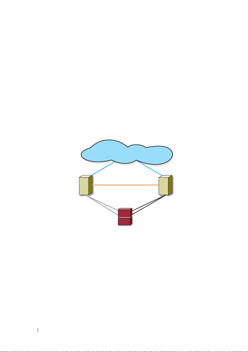
Figure 1-1 shows a basic direct-attached, single-cluster configuration.
Figure 1-1. Direct-Attached, Single-Cluster Configuration
public network
cluster node
Fibre Channel
connections
EMC PowerPath Limitations in a Direct-Attached Cluster
private network
storage system
cluster node
Fibre Channel
connections
EMC PowerPath® provides failover capabilities, multiple path detection, and
dynamic load balancing between multiple ports on the same storage
processor. However, the direct-attached clusters supported by Dell connect to
a single port on each storage processor in the storage system. Because of the
single port limitation, PowerPath can provide only failover protection, not
load balancing, in a direct-attached configuration.
12 Introduction
Page 13
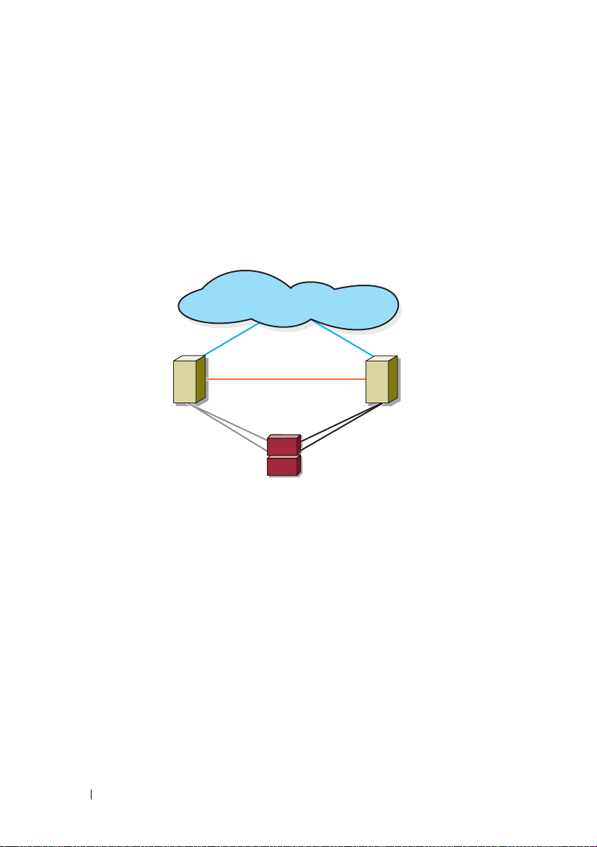
SAN-Attached Cluster
In a SAN-attached cluster, all nodes are attached to a single storage system or
to multiple storage systems through a SAN using redundant switch fabrics.
SAN-attached clusters are superior to direct-attached clusters in
configuration flexibility, expandability, and performance.
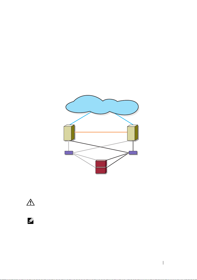
Figure 1-2 shows a SAN-attached cluster.
Figure 1-2. SAN-Attached Cluster
public network
cluster node
private network
Fibre Channel
connections
Fibre Channel switch
storage system
cluster node
Fibre Channel
connections
Fibre Channel switch
Other Documents You May Need
WARNING: The safety information that shipped with your system provides
important safety and regulatory information. Warranty information may be
included within this document or as a separate document.
NOTE: To configure Dell blade server modules in a Dell PowerEdge cluster, see the
Using Dell Blade Servers in a Dell PowerEdge High Availability Cluster document
located on the Dell Support website at support.dell.com.
• The
Rack Installation Guide
included with your rack solution describes
how to install your system into a rack.
Introduction 13
Page 14

•The
Getting Started Guide
provides an overview of initially setting up your
system.
• For more information on deploying your cluster with Windows Server 2003
operating systems, see the
Server 2003 Installation and Troubleshooting Guide
Dell Failover Clusters with Microsoft Windows
.
• For more information on deploying your cluster with Windows Server 2008
operating systems, see the
Server 2008 Installation and Troubleshooting Guide
Dell Failover Clusters with Microsoft Windows
.
• The HBA documentation provides installation instructions for the HBAs.
• Systems management software documentation describes the features,
requirements, installation, and basic operation of the software.
• Operating system documentation describes how to install (if necessary),
configure, and use the operating system software.
• Documentation for any components you purchased separately provides
information to configure and install those options.
• The Dell PowerVault™ tape library documentation provides information
for installing, troubleshooting, and upgrading the tape library.
• Any other documentation that came with your server or storage system.
• The EMC PowerPath documentation that came with your HBA kit(s) and
Dell/EMC Storage Enclosure User’s Guides.
• Updates are sometimes included with the system to describe changes to
the system, software, and/or documentation.
NOTE: Always read the updates first because they often supersede
information in other documents.
• Release notes or readme files may be included to provide last-minute
updates to the system or documentation, or advanced technical reference
material intended for experienced users or technicians.
14 Introduction
Page 15

Cabling Your Cluster Hardware
NOTE: To configure Dell blade server modules in a Dell PowerEdge cluster, see the
Using Dell Blade Servers in a Dell PowerEdge High Availability Cluster document
located on the Dell Support website at support.dell.com.
Cabling the Mouse, Keyboard, and Monitor
When installing a cluster configuration in a rack, you must include a switch
box to connect the mouse, keyboard, and monitor to the nodes. See the
documentation included with your rack for instructions on cabling
connections of each node to the switch box.
Cabling the Power Supplies
See the documentation for each component in your cluster solution and
ensure that the specific power requirements are satisfied.
The following guidelines are recommended to protect your cluster solution
from power-related failures:
• For nodes with multiple power supplies, plug each power supply into a
separate AC circuit.
• Use uninterruptible power supplies (UPS).
• For some environments, consider having backup generators and power
from separate electrical substations.
Figure 2-1 and Figure 2-2 illustrate recommended methods for power cabling
for a cluster solution consisting of two PowerEdge systems and two storage
systems. To ensure redundancy, the primary power supplies of all the
components are grouped into one or two circuits and the redundant power
supplies are grouped into a different circuit.
Cabling Your Cluster Hardware 15
Page 16
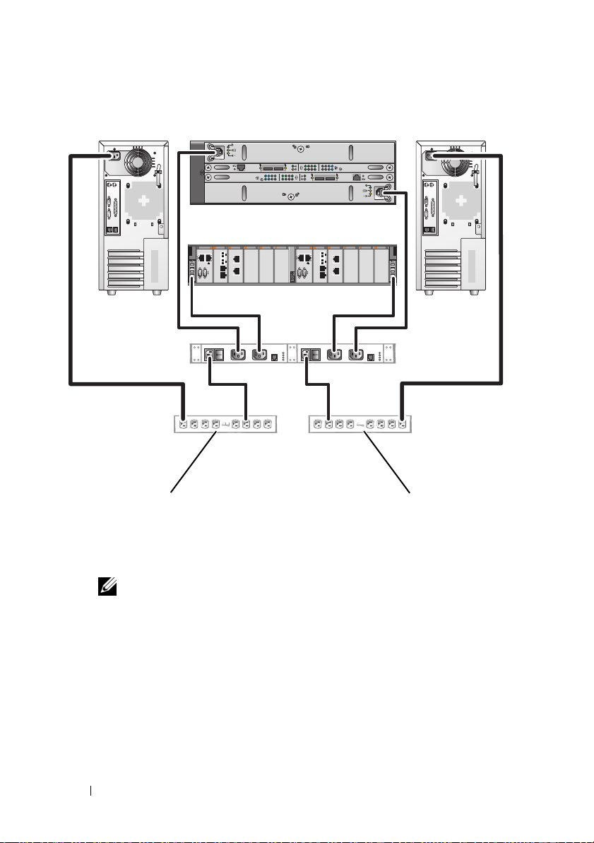
Figure 2-1. Power Cabling Example With One Power Supply in the PowerEdge Systems
primary power supplies
on one AC power strip
(or on one AC Power
Distribution Unit [not
01
0123
01
0123
redundant power
supplies on one AC
power strip (or on one
AC PDU [not shown])
shown])
NOTE: This illustration is intended only to demonstrate the power
distribution of the components.
16 Cabling Your Cluster Hardware
Page 17
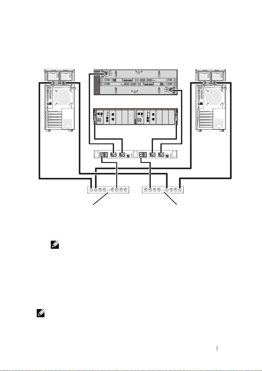
Figure 2-2. Power Cabling Example With Two Power Supplies in the PowerEdge Systems
primary power supplies
on one AC power strip
(or on one AC PDU [not
shown])
01
0123
01
0123
redundant power supplies
on one AC power strip (or
on one AC PDU [not
shown])
NOTE: This illustration is intended only to demonstrate the power
distribution of the components.
Cabling Your Cluster for Public and Private Networks
The network adapters in the cluster nodes provide at least two network
connections for each node, as described in Table 2-1.
NOTE: To configure Dell blade server modules in a Dell PowerEdge cluster, see the
Using Dell Blade Servers in a Dell PowerEdge High Availability Cluster document
located on the Dell Support website at support.dell.com.
Cabling Your Cluster Hardware 17
Page 18
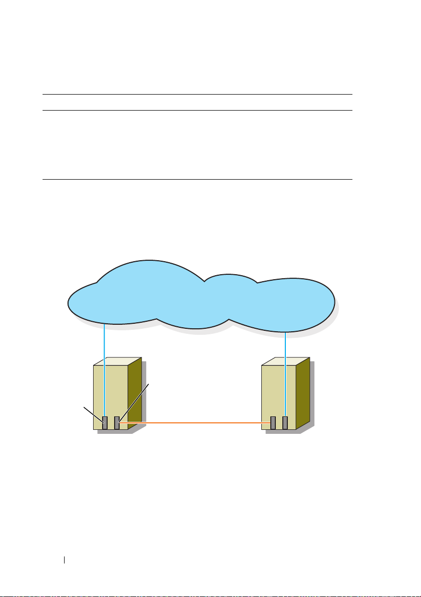
Table 2-1. Network Connections
Network Connection Description
Public network All connections to the client LAN.
At least one public network must be configured for Mixed
mode for private network failover.
Private network A dedicated connection for sharing cluster health and
status information only.
Figure 2-3 shows an example of cabling in which dedicated network adapters
in each node are connected to each other (for the private network) and the
remaining network adapters are connected to the public network.
Figure 2-3. Example of Network Cabling Connection
public network
public
network
adapter
cluster node 1
private network
adapter
private network
cluster node 2
Cabling the Public Network
Any network adapter supported by a system running TCP/IP may be used to
connect to the public network segments. You can install additional network
adapters to support additional public network segments or to provide
redundancy in the event of a faulty primary network adapter or switch port.
18 Cabling Your Cluster Hardware
Page 19
Cabling the Private Network
The private network connection to the nodes is provided by a different
network adapter in each node. This network is used for intra-cluster
communications. Table 2-2 describes three possible private network
configurations.
Table 2-2. Private Network Hardware Components and Connections
Method Hardware Components Connection
Network
switch
Point-to-Point
Gigabit
Ethernet
(two-node
clusters only)
NOTE: Throughout this document, Gigabit Ethernet is used to refer to either Gigabit
Ethernet or 10 Gigabit Ethernet.
Using Dual-Port Network Adapters
You can configure your cluster to use the public network as a failover for
private network communications. If you are using dual-port network adapters,
do not configure both ports simultaneously to support both public and
private networks.
Gigabit Ethernet network
adapters and switches
Copper Gigabit Ethernet
network adapters
Connect standard Ethernet cables
from the network adapters in the
nodes to a Gigabit Ethernet switch.
Connect a standard Ethernet cable
between the Gigabit Ethernet network
adapters in both nodes.
NIC Teaming
NIC teaming combines two or more NICs to provide load balancing and fault
tolerance. Your cluster supports NIC teaming, only in a public network. NIC
teaming is not supported in a private network.
Use the same brand of NICs in a team. Do not mix brands in NIC teaming.
Cabling the Storage Systems
This section provides information on cabling your cluster to a storage system
in a direct-attached configuration or to one or more storage systems in a SANattached configuration.
Cabling Your Cluster Hardware 19
Page 20
Cabling Storage for Your Direct-Attached Cluster
A direct-attached cluster configuration consists of redundant Fibre Channel
host bus adapter (HBA) ports cabled directly to a Dell/EMC storage system.
Figure 2-4 shows an example of a direct-attached, single cluster configuration
with redundant HBA ports installed in each cluster node.
Figure 2-4. Direct-Attached Cluster Configuration
public network
cluster node
Fibre Channel
connections
cluster node
private network
Fibre
Channel
connections
storage system
20 Cabling Your Cluster Hardware
Page 21

Cabling a Cluster to a Dell/EMC Storage System
Each cluster node attaches to the storage system using two Fibre optic cables
with duplex local connector (LC) multimode connectors that attach to the
HBA ports in the cluster nodes and the storage processor (SP) ports in the
Dell/EMC storage system. These connectors consist of two individual Fibre
optic connectors with indexed tabs that must be aligned properly into the
HBA ports and SP ports.
CAUTION: Do not remove the connector covers until you are ready to insert the
connectors into the HBA port, SP port, or tape library port.
Cabling a Two-Node Cluster to a Dell/EMC Storage System
NOTE: The Dell/EMC storage system requires at least 2 front-end fibre channel
ports available on each storage processor.
1
Connect cluster node 1 to the storage system:
a
Install a cable from cluster node 1 HBA port 0 to the first front-end
fibre channel port on SP-A.
b
Install a cable from cluster node 1 HBA port 1 to the first front-end
fibre channel port on SP-B.
2
Connect cluster node 2 to the storage system:
a
Install a cable from cluster node 2 HBA port 0 to the second front-end
fibre channel port on SP-A.
b
Install a cable from cluster node 2 HBA port 1 to the second front-end
fibre channel port on SP-B.
Cabling Your Cluster Hardware 21
Page 22

Figure 2-5. Cabling a Two-Node Cluster to a CX4-120 or CX4-240 Storage System
cluster node 1
HBA ports (2)
HBA ports (2)
01
0123
SP-B
01
0123
SP-A
01
CX4-120 or CX4-240 storage system
Figure 2-6. Cabling a Two-Node Cluster to a CX4-480 Storage System
cluster node 1
HBA ports (2)
HBA ports (2)
01
cluster node 2
10
cluster node 2
10
SP-B
01
0123
0123
CX4-480 storage system
22 Cabling Your Cluster Hardware
0123
0123
SP-A
01
Page 23

Figure 2-7. Cabling a Two-Node Cluster to a CX4-960 Storage System
cluster node 1
HBA ports (2)
01
SP-B
0123 0123
0123001123
01
cluster node 2
HBA ports (2)
10
SP-A
CX4-960 storage system
Cabling a Multi-Node Cluster to a Dell/EMC Storage System
You can configure a cluster with more than two nodes in a direct-attached
configuration using a Dell/EMC storage system, depending on the availability
of front-end fibre channel ports. The CX4-120 and CX4-240 storage systems
can support up to 6-node cluster, the CX4-480 storage system can support up
to 8-node cluster, and the CX4-960 can support up to 12-node cluster.
The following example explains how to cable a four-node cluster:
NOTE: The Dell/EMC storage system requires at least 4 front-end fibre channel
ports available on each storage processor.
NOTE: The following steps can be modified to add more clusters or standalone
systems.
1
Connect cluster node 1 to the storage system:
a
Install a cable from cluster node 1 HBA port 0 to the first front-end
fibre channel port on SP-A.
b
Install a cable from cluster node 1 HBA port 1 to the first front-end
fibre channel port on SP-B.
Cabling Your Cluster Hardware 23
Page 24

2
Connect cluster node 2 to the storage system:
a
Install a cable from cluster node 2 HBA port 0 to the second front-end
fibre channel port on SP-A.
b
Install a cable from cluster node 2 HBA port 1 to the second front-end
fibre channel port on SP-B.
3
Connect cluster node 3 to the storage system:
a
Install a cable from cluster node 3 HBA port 0 to the third front-end
fibre channel port on SP-A.
b
Install a cable from cluster node 3 HBA port 1 to the third front-end
fibre channel port on SP-B.
4
Connect cluster node 4 to the storage system:
a
Install a cable from cluster node 4 HBA port 0 to the fourth front-end
fibre channel port on SP-A.
b
Install a cable from cluster node 4 HBA port 1 to the fourth front-end
fibre channel port on SP-B.
Cabling Multiple Clusters to a Dell/EMC Storage System
The high number of available front-end fibre channel ports on the CX4-series
storage system also allows you to configure multiple clusters or a mix of
cluster(s) and non-clustered server(s) in a direct-attached configuration.
For example, the 6 front-end fibre channel ports per storage processor on
Dell/EMC CX4-120 and CX4-240 storage systems allows you to connect 3
two-node clusters, or 2 two-node clusters and 2 non-clustered systems in a
direct-attached configuration. Similarly, the 8 front-end fibre-channel ports
per storage processor on Dell/EMC CX4-480 storage system allows you to
connect 4 two-node clusters, or 2 two-node clusters and 4 non-clustered
systems in a direct-attached environment.
Similarly, the 12 front-end fibre channel ports per storage processor on
Dell/EMC CX4-960 storage system allows you to connect 6 two-node clusters
or 5 two-node clusters and 2 non-clustered servers in a direct-attached
environment.
NOTE: Enable EMC® Access Control if the CX4-series storage system is connected
to more than one cluster in a direct-attached configuration.
24 Cabling Your Cluster Hardware
Page 25

Cabling Two Two-Node Clusters to a Dell/EMC Storage System
The following steps are an example of how to cable a two two-node cluster.
The Dell/EMC storage system needs to have at least 4 front-end fibre channel
ports available on each storage processor.
In the first cluster, connect cluster node 1 to the storage system:
1
a
Install a cable from cluster node 1 HBA port 0 to the first front-end
fibre channel port on SP-A.
b
Install a cable from cluster node 1 HBA port 1 to the first front-end
fibre channel port on SP-B.
2
In the first cluster, connect cluster node 2 to the storage system:
a
Install a cable from cluster node 2 HBA port 0 to the second front-end
fibre channel port on SP-A.
b
Install a cable from cluster node 2 HBA port 1 to the second front-end
fibre channel port on SP-B.
3
In the second cluster, connect cluster node 1 to the storage system:
a
Install a cable from cluster node 1 HBA port 0 to the third front-end
fibre channel port on SP-A.
b
Install a cable from cluster node 1 HBA port 1 to the third front-end
fibre channel port on SP-B.
4
In the second cluster, connect cluster node 2 to the storage system:
a
Install a cable from cluster node 2 HBA port 0 to the fourth front-end
fibre channel port on SP-A.
b
Install a cable from cluster node 2 HBA port 1 to the fourth front-end
fibre channel port on SP-B.
Cabling Storage for Your SAN-Attached Cluster
A SAN-attached cluster is a cluster configuration where all cluster nodes that
are attached to a single storage system or to multiple storage systems through
SAN use a redundant switch fabric.
SAN-attached cluster configurations provide more flexibility, expandability,
and performance than direct-attached configurations.
See "Implementing Zoning on a Fibre Channel Switched Fabric" on page 42
for more information on Fibre Channel switch fabrics.
Cabling Your Cluster Hardware 25
Page 26

Figure 2-8 shows an example of a two node SAN-attached cluster.
Figure 2-9 shows an example of an eight-node SAN-attached cluster.
Similar cabling concepts can be applied to clusters that contain a different
number of nodes.
NOTE: The connections listed in this section are representative of one proven
method of ensuring redundancy in the connections between the cluster nodes and
the storage system. Other methods that achieve the same type of redundant
connectivity may be acceptable.
Figure 2-8. Two-Node SAN-Attached Cluster
public network
cluster node
private network
Fibre Channel
connections
Fibre Channel
switch
storage system
26 Cabling Your Cluster Hardware
cluster node
Fibre Channel
connections
Fibre Channel
switch
Page 27

Figure 2-9. Eight-Node SAN-Attached Cluster
public network
private
network
cluster nodes (2-8)
Fibre Channel
switch
Fibre Channel
switch
storage system
Cabling Your Cluster Hardware 27
Page 28

Cabling a SAN-Attached Cluster to a Dell/EMC Storage System
The cluster nodes attach to the storage system using a redundant switch
fabric and Fibre optic cables with duplex LC multimode connectors.
The switches, the HBA ports in the cluster nodes, and the SP ports in the
storage system use duplex LC multimode connectors. The connectors consist
of two individual fibre optic connectors with indexed tabs that must be
inserted and aligned properly in the small form-factor pluggable (SFP)
module connectors on the Fibre Channel switches and the connectors on the
cluster nodes and storage systems.
Each HBA port is cabled to a port on a Fibre Channel switch. One or more
cables connect from the outgoing ports on a switch to a storage processor on a
Dell/EMC storage system.
Table 2-3 provides information for cabling your storage system to the Fibre
Channel switches.
Table 2-3. Storage System Cabling Description
Storage System Front-end Fibre
Channel ports per
SP
CX4-120, CX4-240 Two to six ports Four to twelve Attach one cable
CX4-480 Four to eight ports Eight to sixteen
CX4-960 Four to twelve
ports
NOTE: Adding more cables from the storage system to the switches can increase
the I/O bandwidth and high availability of data. Although the CX4-960 has a
maximum of 12 front-end fibre channel ports per SP, only 8 of them can be
connected to fibre channel switches.
Fibre Optic
Cables Required
Eight to sixteen
Cabling
Description
from each storage
processor port to
the Fibre Channel
switch.
Figure 2-10 illustrates the method for cabling a SAN-attached cluster to the
CX4-120 and CX4-240 storage systems.
Figure 2-11 illustrates a method for cabling a SAN-attached cluster to a CX4480 storage system.
Figure 2-12 illustrates a method for cabling a SAN-attached cluster to a
CX4-960 storage system.
28 Cabling Your Cluster Hardware
Page 29

Cabling a SAN-Attached Cluster to a Dell/EMC CX4-120 or CX4-240 Storage
System
1
Connect cluster node 1 to the SAN:
a
Connect a cable from HBA port 0 to Fibre Channel switch 0 (sw0).
b
Connect a cable from HBA port 1 to Fibre Channel switch 1 (sw1).
2
Repeat step 1 for each additional cluster node.
3
Connect the storage system to the SAN:
a
Connect a cable from Fibre Channel switch 0 (sw0) to the first frontend fibre channel port on SP-A.
b
Connect a cable from Fibre Channel switch 0 (sw0) to the first frontend fibre channel port on SP-B.
c
Connect a cable from Fibre Channel switch 1 (sw1) to the second
front-end fibre channel port on SP-A.
d
Connect a cable from Fibre Channel switch 1 (sw1) to the second
front-end fibre channel port on SP-B.
NOTE: Additional cables can be connected from the fibre channel switches to the
storage system if there are available front-end fibre channel ports on the storage
processors.
Cabling Your Cluster Hardware 29
Page 30

Figure 2-10. Cabling a SAN-Attached Cluster to the Dell/EMC CX4-120 or CX4-240
cluster node 1
1
0
sw0
HBA ports (2)
SP-B
01
0123
HBA ports (2)
SP-A
01
0123
cluster node 2
0
1
sw1
CX4-120 or CX4-240 storage system
Cabling a SAN-Attached Cluster to the Dell/EMC CX4-480 or CX4-960 Storage
System
1
Connect cluster node 1 to the SAN:
a
Connect a cable from HBA port 0 to Fibre Channel switch 0 (sw0).
b
Connect a cable from HBA port 1 to Fibre Channel switch 1 (sw1).
2
Repeat step 1 for each additional cluster node.
3
Connect the storage system to the SAN:
a
Connect a cable from Fibre Channel switch 0 (sw0) to the first frontend fibre channel port on SP-A.
b
Connect a cable from Fibre Channel switch 0 (sw0) to the first frontend fibre channel port on SP-B.
c
Connect a cable from Fibre Channel switch 0 (sw0) to the second
front-end fibre channel port on SP-A.
30 Cabling Your Cluster Hardware
Page 31

d
Connect a cable from Fibre Channel switch 0 (sw0) to the second
front-end fibre channel port on SP-B.
e
Connect a cable from Fibre Channel switch 1 (sw1) to the third frontend fibre channel port on SP-A.
f
Connect a cable from Fibre Channel switch 1 (sw1) to the third frontend fibre channel port on SP-B.
g
Connect a cable from Fibre Channel switch 1 (sw1) to the fourth
front-end fibre channel port on SP-A.
h
Connect a cable from Fibre Channel switch 1 (sw1) to the fourth
front-end fibre channel port on SP-B.
NOTE: Additional cables can be connected from the fibre channel switches to the
storage system if there are available front-end fibre channel ports on the storage
processors.
Figure 2-11. Cabling a SAN-Attached Cluster to the Dell/EMC CX4-480
cluster node 1
1
0
sw0
HBA ports (2)
0123
0123
SP-B
01
CX4-480 storage system
Cabling Your Cluster Hardware 31
HBA ports (2)
0123
0123
SP-A
01
cluster node 2
0
1
sw1
Page 32
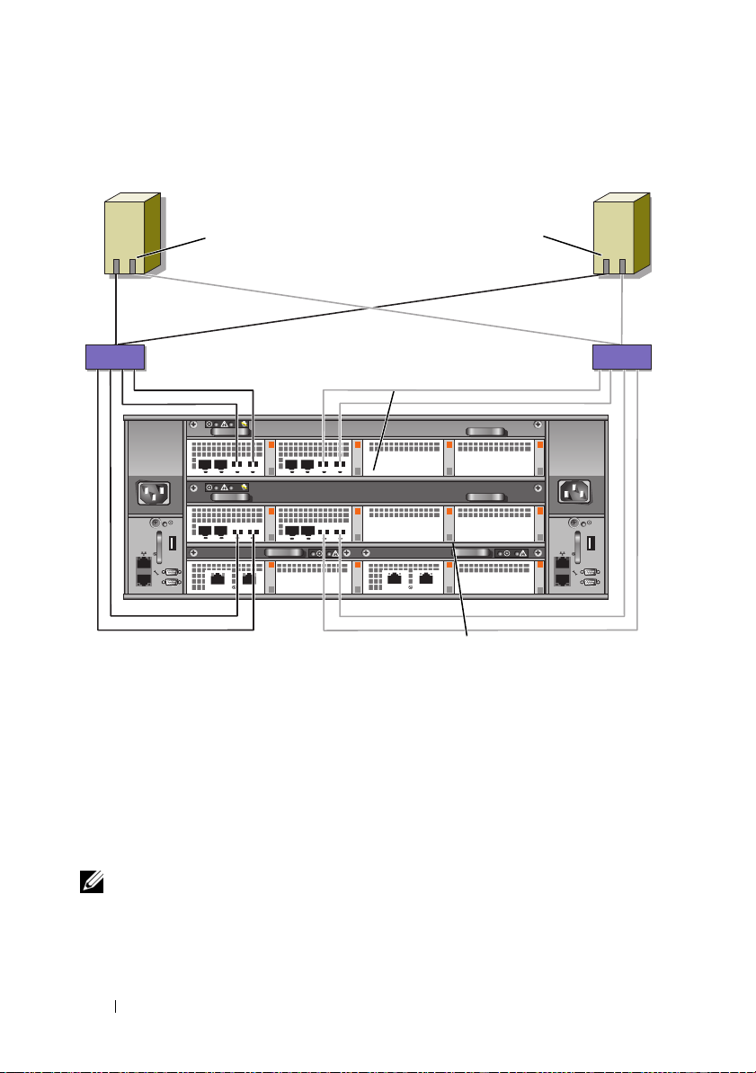
Figure 2-12. Cabling a SAN-Attached Cluster to the Dell\EMC CX4-960
cluster node 2cluster node 1
01
HBA ports (2)
sw0 sw1
Fibre Channel switch
HBA ports (2)
01
Fibre Channel switch
SP-B
0 1 23 0 1 23
0123001123
01
CX4-960 storage system
SP-A
Cabling Multiple SAN-Attached Clusters to a Dell/EMC Storage System
To cable multiple clusters to the storage system, connect the cluster nodes to
the appropriate Fibre Channel switches and then connect the Fibre Channel
switches to the appropriate storage processors on the processor enclosure.
For rules and guidelines for SAN-attached clusters, see the Dell Cluster
Configuration Support Matrix on the Dell High Availability website at
www.dell.com/ha.
NOTE: The following procedures use Figure 2-10, Figure 2-11, and Figure 2-12 as
examples for cabling additional clusters.
32 Cabling Your Cluster Hardware
Page 33

Cabling Multiple SAN-Attached Clusters to the CX4-120 or CX4-240
Storage System
1
In the first cluster, connect cluster node 1 to the SAN:
a
Connect a cable from HBA port 0 to Fibre Channel switch 0 (sw0).
b
Connect a cable from HBA port 1 to Fibre Channel switch 1 (sw1).
2
In the first cluster, repeat step 1 for each additional cluster node.
3
For each additional cluster, repeat step 1 and step 2.
4
Connect the storage system to the SAN:
a
Connect a cable from Fibre Channel switch 0 (sw0) to the first frontend fibre channel port on SP-A.
b
Connect a cable from Fibre Channel switch 0 (sw0) to the first frontend fibre channel port on SP-B.
c
Connect a cable from Fibre Channel switch 1 (sw1) to the second
front-end fibre channel port on SP-A.
d
Connect a cable from Fibre Channel switch 1 (sw1) to the second
front-end fibre channel port on SP-B.
NOTE: Additional cables can be connected from the fibre channel switches to the
storage system if there are available front-end fibre channel ports on the storage
processors.
Cabling Multiple SAN-Attached Clusters to the CX4-480 or CX4-960Storage System
1
In the first cluster, connect cluster node 1 to the SAN:
a
Connect a cable from HBA port 0 to Fibre Channel switch 0 (sw0).
b
Connect a cable from HBA port 1 to Fibre Channel switch 1 (sw1).
2
In the first cluster, repeat step 1 for each additional cluster node.
3
For each additional cluster, repeat step 1 and step 2.
4
Connect the storage system to the SAN:
a
Connect a cable from Fibre Channel switch 0 (sw0) to the first frontend fibre channel port on SP-A.
b
Connect a cable from Fibre Channel switch 0 (sw0) to the first frontend fibre channel port on SP-B.
Cabling Your Cluster Hardware 33
Page 34

c
Connect a cable from Fibre Channel switch 0 (sw0) to the second
front-end fibre channel port on SP-A.
d
Connect a cable from Fibre Channel switch 0 (sw0) to the second
front-end fibre channel port on SP-B.
e
Connect a cable from Fibre Channel switch 1 (sw1) to the third frontend fibre channel port on SP-A.
f
Connect a cable from Fibre Channel switch 1 (sw1) to the third frontend fibre channel port on SP-B.
g
Connect a cable from Fibre Channel switch 1 (sw1) to the fourth
front-end fibre channel port on SP-A.
h
Connect a cable from Fibre Channel switch 1 (sw1) to the fourth
front-end fibre channel port on SP-B.
NOTE: Additional cables can be connected from the fibre channel switches to the
storage system if there are available front-end fibre channel ports on the storage
processors.
Zoning Your Dell/EMC Storage System in a Switched Environment
Dell only supports single-initiator zoning for connecting clusters to a
Dell/EMC storage system in a switched environment. When using EMC
PowerPath, a separate zone is created from each HBA port to the SPE.
Connecting a PowerEdge Cluster to Multiple Storage Systems
You can increase your cluster storage capacity by attaching multiple storage
systems to your cluster using a redundant switch fabric. Failover Clusters can
support configurations with multiple storage units attached to clustered nodes. In
this scenario, the Microsoft Cluster Service (MSCS) software can fail over disk
drives in any cluster-attached shared storage array between the cluster nodes.
NOTE: Throughout this document, MSCS is used to refer to either the Microsoft
Windows Server 2003 Cluster Service or the Microsoft Windows Server 2008
Failover Cluster Service.
When attaching multiple storage systems with your cluster, the following
rules apply:
• There is a maximum of four storage systems per cluster.
• The shared storage systems and firmware must be identical. Using dissimilar
storage systems and firmware for your shared storage is not supported.
34 Cabling Your Cluster Hardware
Page 35

• MSCS is limited to 22 drive letters. Because drive letters A through D are
reserved for local disks, a maximum of 22 drive letters (E to Z) can be used
for your storage system disks.
• Windows Server 2003 and 2008 support mount points, allowing greater
than 22 drives per cluster.
Figure 2-13 provides an example of cabling the cluster nodes to four
Dell/EMC storage systems. See "Implementing Zoning on a Fibre Channel
Switched Fabric" on page 42 for more information.
Figure 2-13. PowerEdge Cluster Nodes Cabled to Four Storage Systems
cluster node
private network
Fibre Channel
switch
storage systems (4)
Connecting a PowerEdge Cluster to a Tape Library
cluster node
Fibre Channel
switch
To provide additional backup for your cluster, you can add tape backup devices
to your cluster configuration. The Dell PowerVault™ tape libraries may contain
an integrated Fibre Channel bridge or Storage Network Controller (SNC) that
connects directly to your Fibre Channel switch.
Figure 2-14 shows a supported Failover Cluster configuration using
redundant Fibre Channel switches and a tape library. In this configuration,
each of the cluster nodes can access the tape library to provide backup for
your local disk resources, as well as your cluster disk resources. Using this
configuration allows you to add more servers and storage systems in the
future, if needed.
Cabling Your Cluster Hardware 35
Page 36

NOTE: While tape libraries can be connected to multiple fabrics, they do not
provide path failover.
Figure 2-14. Cabling a Storage System and a Tape Library
Fibre Channel
switch
tape library
cluster node
private network
storage system
cluster node
Fibre Channel
switch
Obtaining More Information
See the storage and tape backup documentation for more information on
configuring these components.
Configuring Your Cluster With SAN Backup
You can provide centralized backup for your clusters by sharing your SAN
with multiple clusters, storage systems, and a tape library.
Figure 2-15 provides an example of cabling the cluster nodes to your storage
systems and SAN backup with a tape library.
36 Cabling Your Cluster Hardware
Page 37
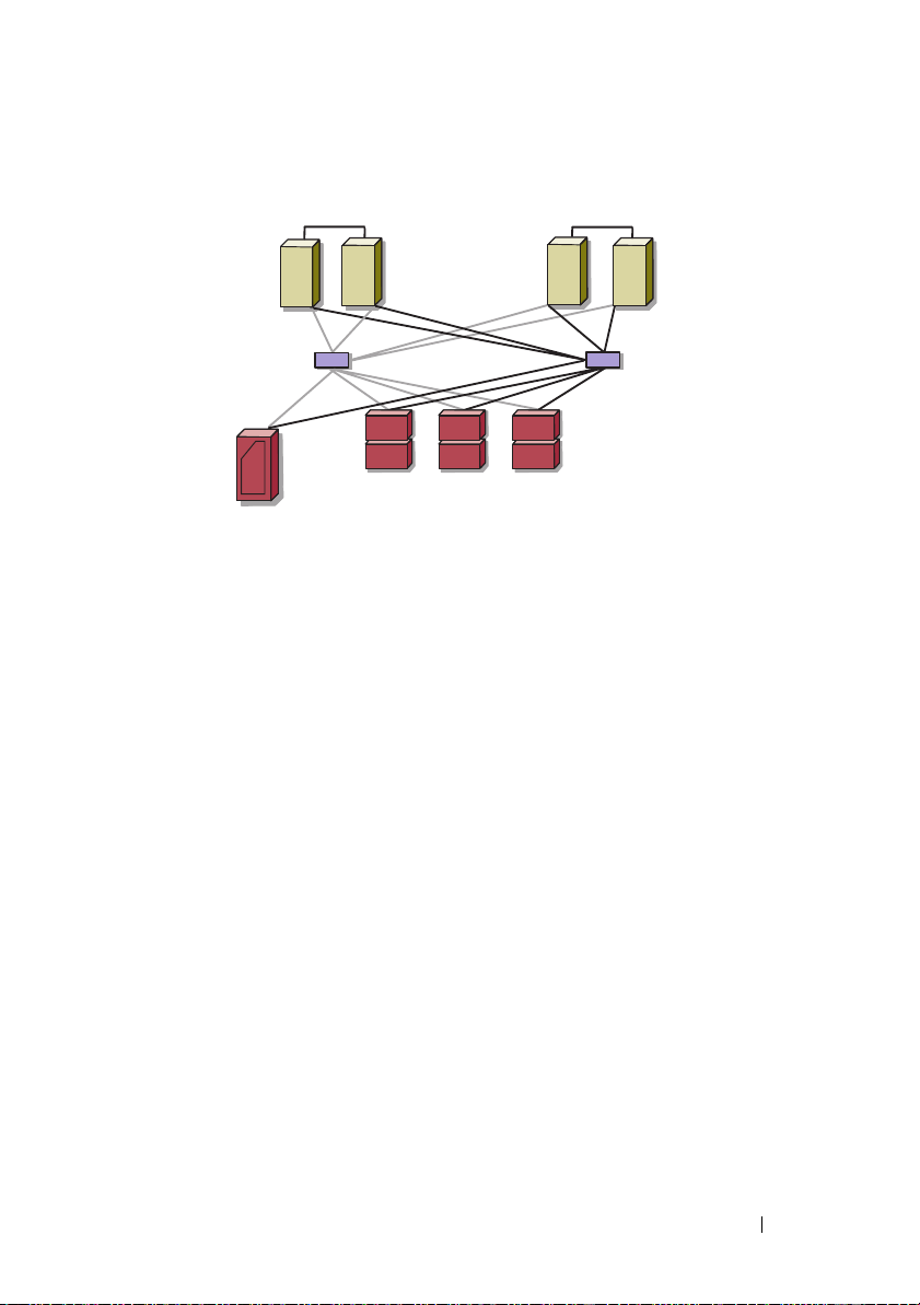
Figure 2-15. Cluster Configuration Using SAN-Based Backup
cluster 2cluster 1
Fibre Channel switch
tape library
Fibre Channel switch
storage systems
Cabling Your Cluster Hardware 37
Page 38

38 Cabling Your Cluster Hardware
Page 39

Preparing Your Systems for Clustering
WARNING: Only trained service technicians are authorized to remove and
access any of the components inside the system. See your safety information for
complete information about safety precautions, working inside the computer, and
protecting against electrostatic discharge.
Cluster Configuration Overview
1
Ensure that your site can handle the cluster’s power requirements.
Contact your sales representative for information about your region's
power requirements.
2
Install the systems, the shared storage array(s), and the interconnect
switches (for example, in an equipment rack), and ensure that all the
components are turned on.
NOTE: For more information on step 3 to step 7 and step 10 to step 13, see the
"Preparing your systems for clustering" section of Dell Failover Clusters with
Microsoft Windows Server 2003 Installation and Troubleshooting Guide or
Dell Failover Clusters with Microsoft Windows Server 2008 Installation and
Troubleshooting Guide located on the Dell Support website at
support.dell.com.
3
Deploy the operating system (including any relevant service packs and
hotfixes), network adapter drivers, and storage adapter drivers (including
Multipath I/O (MPIO) drivers) on each cluster node. Depending on the
deployment method that is used, it may be necessary to provide a network
connection to successfully complete this step.
NOTE: To help in planning and deployment of your cluster, record the relevant
cluster configuration information in the Cluster Data Form located at "Cluster
Data Form" on page 63 and the Zoning configuration information in the Zoning
Configuration form located and "Zoning Configuration Form" on page 61.
4
Establish the physical network topology and the TCP/IP settings for
network adapters on each cluster node to provide access to the cluster
public and private networks.
Preparing Your Systems for Clustering 39
Page 40

5
Configure each cluster node as a member in the same Windows Active
Directory Domain.
NOTE: You can configure the cluster nodes as Domain Controllers. For more
information, see the “Selecting a Domain Model” section of Dell Failover
Clusters with Microsoft Windows Server 2003 Installation and
Troubleshooting Guide or Dell Failover Clusters with Microsoft Windows
Server 2008 Installation and Troubleshooting Guide located on the Dell
Support website at support.dell.com.
6
Establish the physical storage topology and any required storage network
settings to provide connectivity between the storage array and the systems
that you are configuring as cluster nodes. Configure the storage system(s)
as described in your storage system documentation.
7
Use storage array management tools to create at least one logical unit
number (LUN). The LUN is used as a cluster Quorum disk for Windows
Server 2003 Failover cluster and as a Witness disk for Windows Server 2008
Failover cluster. Ensure that this LUN is presented to the systems that you
are configuring as cluster nodes.
NOTE: For security reasons, it is recommended that you configure the LUN on
a single node as mentioned in step 8 when you are setting up the cluster.
Later, you can configure the LUN as mentioned in step 9 so that other nodes in
the cluster can access it.
8
Select one of the systems and form a new failover cluster by configuring
the cluster name, cluster management IP, and quorum resource. For more
information, see "Preparing Your Systems for Clustering" on page 39.
NOTE: For Failover Clusters configured with Windows Server 2008, run the
Cluster Validation Wizard to ensure that your system is ready to form the
cluster.
9
Join the remaining node(s) to the failover cluster. For more information,
see "Preparing Your Systems for Clustering" on page 39.
10
Configure roles for cluster networks.
11
Test the failover capabilities of your new cluster.
NOTE: For Failover Clusters configured with Windows Server 2008, you can
also use the Cluster Validation Wizard.
40 Preparing Your Systems for Clustering
Page 41

12
Configure highly-available applications and services on your Failover
Cluster. Depending on your configuration, this may also require providing
additional LUNs to the cluster or creating new cluster resource groups.
Test the failover capabilities of the new resources.
13
Configure client systems to access the highly-available applications and
services that are hosted on your failover cluster.
Installation Overview
Each node in your Dell Failover Cluster must be installed with the same
release, edition, service pack, and processor architecture of the Windows
Server operating system. For example, all nodes in your cluster may be
configured with Windows Server 2003 R2, Enterprise x64 Edition. If the
operating system varies among nodes, it is not possible to configure a Failover
Cluster successfully. It is recommended to establish server roles prior to
configuring a Failover Cluster, depending on the operating system configured
on your cluster.
For a list of Dell PowerEdge Servers, Fibre Channel HBAs and switches, and
recommended list of operating system variants, specific driver and firmware
revisions, see the Dell Cluster Configuration Support Matrix on the Dell High
Availability website at www.dell.com/ha.
For a general overview of cluster configuration tasks and more detailed
information about deploying your cluster with Windows Server 2003
operating system, see the Dell Failover Clusters with Microsoft Windows
Server 2003 Installation and Troubleshooting Guide located on the Dell
Support website at support.dell.com.
For more information on deploying your cluster with Windows Server 2008
operating systems, see the Dell Failover Clusters with Microsoft Windows
Server 2008 Installation and Troubleshooting Guide located on the Dell
Support website at support.dell.com.
The following sub-sections describe steps that must be taken to enable
communication between the cluster nodes and your shared Dell/EMC
CX4-series Fibre Channel storage array, and to present disks from the storage
array to the cluster.
Preparing Your Systems for Clustering 41
Page 42

Installing the Fibre Channel HBAs
For dual -HBA configurations, it is recommended that you install the Fibre
Channel HBAs on separate peripheral component interconnect (PCI) buses.
Placing the adapters on separate buses improves availability and performance.
For more information about your system's PCI bus configuration and
supported HBAs, see the Dell Cluster Configuration Support Matrix on the
Dell High Availability website at www.dell.com/ha.
Installing the Fibre Channel HBA Drivers
For more information, see the EMC documentation that is included with
your HBA kit.
For more information about installing and configuring Emulex HBAs and
EMC-approved drivers, see the Emulex support website located at
www.emulex.com or the Dell Support website at support.dell.com.
For more information about installing and configuring QLogic HBAs and
EMC-approved drivers, see the QLogic support website at www.qlogic.com or
the Dell Support website at support.dell.com.
For more information about supported HBA controllers and drivers, see the
Dell Cluster Configuration Support Matrix on the Dell High Availability
website at www.dell.com/ha.
Implementing Zoning on a Fibre Channel Switched Fabric
A Fibre Channel switched fabric consists of one or more Fibre Channel switches
that provide high-speed connections between servers and storage devices. The
switches in a Fibre Channel fabric provide a connection through inbound and
outbound points from one device (sender) to another device or switch (receiver)
on the network. If the data is sent to another switch, the process repeats itself
until a connection is established between the sender and the receiver.
Fibre Channel switches provide you with the ability to set up barriers between
different devices and operating environments. These barriers create logical
fabric subsets with minimal software and hardware intervention. Similar to
subnets in the client/server network, logical fabric subsets divide a fabric into
similar groups of components, regardless of their proximity to one another.
The logical subsets that form these barriers are called zones.
42 Preparing Your Systems for Clustering
Page 43

Zoning automatically and transparently enforces access of information to the
zone devices. More than one PowerEdge cluster configuration can share
Dell/EMC storage system(s) in a switched fabric using Fibre Channel switch
zoning and with Access Control enabled. By using Fibre Channel switches to
implement zoning, you can segment the SANs to isolate heterogeneous
servers and storage systems from each other.
Using Zoning in SAN Configurations Containing Multiple Hosts
Using the combination of zoning and Access Control in SAN configurations
containing multiple hosts, you can restrict server access to specific volumes
on a shared storage system by preventing the hosts from discovering a storage
volume that belongs to another host. This configuration allows multiple
clustered or nonclustered hosts to share a storage system.
Using Worldwide Port Name Zoning
PowerEdge cluster configurations support worldwide port name zoning.
A worldwide name (WWN) is a unique numeric identifier assigned to Fibre
Channel interfaces, such as HBA ports, storage processor (SP) ports, and
Fibre Channel to SCSI bridges or storage network controllers (SNCs).
A WWN consists of an 8-byte hexadecimal number with each byte separated
by a colon. For example, 10:00:00:60:69:00:00:8a is a valid WWN. Using
WWN port name zoning allows you to move cables between switch ports
within the fabric without having to update the zones.
Table 3-1 provides a list of WWN identifiers that you can find in the
Dell/EMC cluster environment.
Table 3-1. Port Worldwide Names in a SAN Environment
Identifier Description
xx:xx:
xx:xx:xx:
50:06:01:6
xx:xx:00:
xx:xx:
xx:xx
00:60:69:
00:88:
x:xx:xx:xx:xx
00:C9:
00:E0:8B:
:00:0F:1F:
xx:xx:xx
xx:xx:xx
xx:xx:xx
xx:xx:xx
xx:xx:xx
Dell/EMC or Brocade switch
McData switch
Dell/EMC storage processor
Emulex HBA ports
QLogic HBA ports (non-embedded)
Dell 2362M HBA port
Preparing Your Systems for Clustering 43
Page 44
Table 3-1. Port Worldwide Names in a SAN Environment (continued)
Identifier Description
xx:xx:xx:
xx:xx:xx:
xx:xx:xx
xx:xx:xx:C0:97:xx:xx:xx PowerVault ML6000 Fibre Channel tape drives
CAUTION: When you replace a Fibre Channel HBA in a PowerEdge server,
60:45:
E0:02:
:C0:01:
reconfigure your zones to provide continuous client data access. Additionally,
when you replace a switch module, reconfigure your zones to prevent data loss or
corruption.
xx:xx:xx
xx:xx:xx
xx:xx:xx
PowerVault 132T and 136T tape libraries
PowerVault 128T tape autoloader
PowerVault 160T tape library and Fibre
Channel tape drives
CAUTION: You must configure your zones before you configure the logical unit
numbers (LUNs) and storage groups. Failure to do so may cause data loss, data
corruption, or data unavailability.
Single Initiator Zoning
Each host HBA port in a SAN must be configured in a separate zone on the
switch with the appropriate storage ports. This zoning configuration, known
as single initiator zoning, prevents different hosts from communicating with
each other, thereby ensuring that Fibre Channel communications between
the HBAs and their target storage systems do not affect each other.
When you create your single-initiator zones, follow these guidelines:
• Create a zone for each HBA port and its target storage devices.
• Each CX4-series storage processor port can be connected to a maximum of
64 HBA ports in a SAN-attached environment.
• Each host can be connected to a maximum of four storage systems.
•The
integrated bridge/SNC or fibre-channel interface
on a tape library
can be added to any zone.
NOTE: If you are sharing a storage system with multiple clusters or a combination
of clustered and nonclustered systems (hosts), you must enable Access Control.
Otherwise, you can only have one nonclustered system or one PowerEdge cluster
attached to the Dell/EMC storage system.
44 Preparing Your Systems for Clustering
Page 45

Installing and Configuring the Shared Storage System
See "Cluster Hardware Requirements" on page 8 for a list of supported
Dell/EMC storage systems.
To install and configure the Dell/EMC storage system in your cluster:
1
Update the core software on your storage system and enable Access
Control (optional) and install any additional software options, including
EMC SnapView™, EMC MirrorView™, and SAN Copy™. See your EMC
Navisphere
2
Install the EMC Navisphere Agent and EMC PowerPath software on each
cluster node.
See your Navisphere documentation for more information.
3
Update the storage system configuration settings using Navisphere
Manager.
See "Enabling Access Control and Creating Storage Groups Using
Navisphere" on page 49 for more information.
The following subsections provide an overview of the storage management
software and procedures for connecting the host systems to the storage
systems.
Access Control
Fibre Channel topologies allow multiple clusters and stand-alone systems to
share a single storage system. However, if you cannot control access to the
shared storage system, you can corrupt your data. To share your Dell/EMC
storage system with multiple heterogeneous host systems and restrict access
to the shared storage system, you need to enable Access Control.
Enabling Access Control prevents all host systems from accessing any data on
the storage system until they are given explicit access to a LUN through a
storage group. By enabling Access Control, you can prevent the host systems
from taking ownership of all LUNs on the storage system and prevent
unauthorized access to sensitive information.
®
documentation for more information.
Preparing Your Systems for Clustering 45
Page 46

Access Control is enabled using Navisphere Manager. After you enable Access
Control and connect to the storage system from a management station,
Access Control appears in the Storage System Properties window of
Navisphere Manager.
After you enable Access Control, the host system can only read from and
write to specific LUNs on the storage system. This organized group of LUNs
and hosts is called a storage group.
Storage Groups
A storage group is a collection of one or more LUNs that are assigned to one
or more host systems. Managed by Navisphere Manager, storage groups
provide an organized method of assigning multiple LUNs to a host system.
After you create LUNs on your storage system, you can assign the LUNs to a
storage group in Navisphere Manager and then assign the storage group to a
specific host. Because the host can only access its assigned storage group, it
cannot access any LUNs assigned to other host systems, thereby protecting
your data from unauthorized access.
To create the storage groups for your host systems, you must use Navisphere
Manager and enable Access Control in the storage system.
NOTE: A host system can access only one storage group per storage system.
Table 3-2 describes the properties in the storage group.
46 Preparing Your Systems for Clustering
Page 47

Table 3-2. Storage Group Properties
Property Description
Unique ID A unique identifier that is automatically assigned to the
storage group that cannot be changed.
Storage group name The name of the storage group. The default storage
group name is formatted as Storage Group n, where n
equals the existing number of storage groups plus one.
Connected hosts Lists the host systems connected to the storage group.
Each host entry contains the following fields:
•
Name
— Name of the host system
IP address
•
•
OS
system
— IP address of the host system
— Operating system that is running on the host
NOTE: In a clustered environment, all nodes of a cluster
must be connected to the same storage group.
Used host connection
paths
LUNs in storage group Lists the LUNs in the storage group.
An additional storage group feature that performs the
following tasks:
• Lists all of the paths from the host server to the storage
group
• Displays whether the path is enabled or disabled
Each path contains the following fields:
HBA
— Device name of the HBA in the host system
–
HBA Port
–
to the storage system
SP Port
–
connected to the HBA port
SP ID
–
Each LUN entry contains the following fields:
•
Identifier
Name
•
Capacity
•
LUN
— Unique ID for the HBA port connected
— Unique ID for the storage processor port
— ID of the storage processor
— LUN icon representing the LUN
— Name of the LUN
— Amount of allocated storage space on the
Preparing Your Systems for Clustering 47
Page 48

Navisphere Manager
Navisphere Manager provides centralized storage management and
configuration from a single management console. Using a graphical user
interface (GUI), Navisphere Manager allows you to configure and manage the
disks and components in one or more shared storage systems.
You can access Navisphere Manager through a web browser. Using Navisphere
Manager, you can manage a Dell/EMC storage system either locally on the
same LAN or through an Internet connection. Navisphere components
(Navisphere Manager user interface (UI) and Storage Management Server)
are installed on a Dell/EMC storage system. You can access Navisphere
Manager by opening a browser and entering the IP address of the storage
system’s SP. Navisphere Manager downloads components to your system and
runs in the web browser.
Optionally, you can run Navisphere Management Server for Windows. This
software component installs on a host system connected to a Dell/EMC
storage system, allowing you to run Navisphere Storage Management Server
on the host system.
Using Navisphere Manager, you can:
• Create storage groups for your host systems
• Create, bind, and unbind LUNs
• Change configuration settings
• Monitor storage systems
Navisphere Agent
Navisphere Agent is installed on the host system and performs the following
tasks:
• Registers each host with the storage system
• Communicates configuration information from the host to the storage system
In a cluster environment, a NIC may have multiple IP addresses bound to it. To
ensure that the agent registers the host to the storage system with the correct IP
address, perform the following steps:
1
Using a text editor to create a file named
Files\EMC\Navisphere
(x86)\EMC\Navisphere
48 Preparing Your Systems for Clustering
directory (or
for Windows Server 2008 and 2003 (64-bit) systems).
agentID.txt
C:\Program Files
in the
C:\Program
Page 49

2
Add the following two separate lines to the
agentID.txt
file, with no
special formatting:
• First line: Fully qualified hostname. For example, enter
node1.domain1.com
domain1
is
.
, if the host name is
node1
and the domain name
• Second line: IP address that you want the agent to register and use to
communicate with the storage system.
EMC PowerPath
EMC PowerPath® automatically reroutes Fibre Channel I/O traffic from the host
system and a Dell/EMC CX4-series storage system to any available path if a
primary path fails for any reason. Additionally, PowerPath provides multiple path
load balancing, allowing you to balance the I/O traffic across multiple SP ports.
Enabling Access Control and Creating Storage Groups Using Navisphere
The following subsection provides the required procedures for creating
storage groups and connecting your storage systems to the host systems.
CAUTION: Before enabling Access Control, ensure that no hosts are attempting to
access the storage system. Enabling Access Control prevents all hosts from
accessing any data until they are given explicit access to a LUN in the appropriate
storage group. You must stop all I/O before enabling Access Control. It is
recommended to turn off all hosts connected to the storage system during this
procedure or data loss may occur. After you enable the Access Control software, it
cannot be disabled.
1
Ensure that Navisphere Agent is started on all host systems.
a
Click the
and then select
b
In the
•In the
•In the
•In the
2
Open a Web browser.
Start
Services
Name
Status
Startup Type
button and select
Services
.
Programs→ Administrative Tools
window, verify the following:
column,
column,
Navisphere Agent
Navisphere Agent
column,
Navisphere Agent
appears.
is set to
is set to
Started
Automatic
,
.
.
Preparing Your Systems for Clustering 49
Page 50

3
Enter the IP address of the storage management server on your storage
system and then press <Enter>.
NOTE: The storage management server is usually one of the SPs on your
storage system.
4
In the
Enterprise Storage
5
Right-click the icon of your storage system.
6
In the drop-down menu, click
Storage Systems Properties
The
window, click the
Properties
.
window appears.
Storage
tab.
7Click the
8
Select the
Storage Access
tab.
Access Control Enabled
check box.
A dialog box appears, prompting you to enable
9
Click
Yes
to enable
10
Click OK.
11
Right-click the icon of your storage system and select
Create Storage Group
The
12
In the
Storage Group Name
13
Click
Apply
.
14
Add new LUNs to the storage group.
a
Right-click the icon of your storage group and select
b
Click the
c
In the
Available LUNs
d
Click the right-arrow button to move the selected LUN to the
Selected LUNs
e
Click
Apply
15
Add new hosts to the
a
In the
Storage Group Properties
b
In the
Available Hosts
Access Control
LUNs
tab.
pane.
.
Sharable
.
dialog box appears.
field, enter a name for the storage group.
window, click an available LUN.
storage group.
dialog box, click the
window pane, click the host system that you
want to add to the storage group.
c
Using the right-arrow button, move the selected host to the
be Connected
window pane.
Access Control
.
Create Storage Group
Properties
Hosts
.
.
tab.
Hosts to
50 Preparing Your Systems for Clustering
Page 51

d
Repeat step b and step c to add additional hosts.
e
Click
Apply
.
16
Click OK to exit the
Storage Group Properties
dialog box.
Configuring the Hard Drives on the Shared Storage System(s)
This section provides information for configuring the hard drives on the
shared storage systems. The shared storage system hard drives must be
configured before use. The following sections provide information on these
configurations.
Configuring and Managing LUNs
Configuring and managing LUNs is accomplished using the Navisphere
Manager utility. Before using Navisphere Manager, ensure that the Navisphere
Agent service is started on your cluster nodes.
In some cases, the LUNs may have been bound when the system was shipped.
It is still important, however, to install the management software and to verify
that the desired LUN configuration exists.
You can manage your LUNs remotely using Navisphere Manager. A minimum
of one LUN (RAID drive) is required for an active/passive configuration; at
least two drives are required for an active/active configuration.
It is recommended that you create at least one LUN or virtual disk for each
application. If multiple NTFS partitions are created on a single LUN or
virtual disk, these partitions will not be able to fail over individually from
node-to-node.
Configuring the RAID Level for the Shared Storage Subsystem
The hard drives in your shared storage subsystem must be configured into
LUNs or virtual disks using Navisphere Manager. All LUNs or virtual disks,
especially if they are used for the quorum resource, should be bound and
incorporate the appropriate RAID level to ensure high availability.
NOTE: It is recommended that you use a RAID level other than RAID 0 (which is
commonly called striping). RAID 0 configurations provide very high performance,
but do not provide the level of availability required for the quorum resource. See the
documentation for your storage system for more information about setting up RAID
levels for the system.
Preparing Your Systems for Clustering 51
Page 52

Assigning LUNs to Hosts
If you have Access Control enabled in Navisphere Manager, you must create
storage groups and assign LUNs to the proper host systems.
Optional Storage Features
Your Dell/EMC CX4-series storage array may be configured to provide
optional features that can be used in conjunction with your cluster. These
features include MirrorView, SnapView, and SANCopy.
MirrorView
MirrorView automatically duplicates primary storage system data from a
cluster or stand-alone system to a secondary storage system. It can be used in
conjunction with SnapView and is managed from within Navisphere Manager.
SnapView
SnapView captures images of a LUN and retains the images independently of
subsequent changes to the files. The images can be used to share LUNs with
another system without affecting the contents of the source LUN.
SnapView creates copies of LUNs using either snapshots or clones. Snapshots
are virtual copies that create an image of the source LUN at the time the
snapshot was created. This snapshot is retained independently of subsequent
changes to the source LUN. Clones are duplicate copies of a source LUN. You
can use snapshots and clones to facilitate backups or to allow multiple hosts
to access data without affecting the contents of the source LUN.
The source LUN and each snapshot or clone must be accessed from a
different host or a different cluster.
SnapView, which is installed on the storage processors as a non-disruptive
upgrade, can be used in conjunction with MirrorView and is managed from
within Navisphere Manager.
SAN Copy
SAN Copy allows you to move data between storage systems without using
host processor cycles or LAN bandwidth. It can be used in conjunction with
SnapView or MirrorView and is managed from within Navisphere Manager.
52 Preparing Your Systems for Clustering
Page 53

Updating a Dell/EMC Storage System for Clustering
If you are updating an existing Dell/EMC storage system to meet the cluster
requirements for the shared storage subsystem, you may need to install
additional Fibre Channel disk drives in the shared storage system. The size
and number of drives you add depend on the RAID level you want to use and
the number of Fibre Channel disk drives currently in your system.
See your storage system's documentation for information on installing Fibre
Channel disk drives in your storage system.
Upgrade the core software version that is running on the storage system or
enable Access Control. For specific version requirements, see the Dell Cluster
Configuration Support Matrix on the Dell High Availability website at
www.dell.com/ha.
Installing and Configuring a Failover Cluster
After you have established the private and public networks and have assigned
the shared disks from the storage array to the cluster nodes, you can configure
the operating system services on your Dell Failover Cluster. The procedure to
configure the Failover Cluster depends on the version of the Windows Server
operating system that is running on the system.
For more information on deploying your cluster with Windows Server 2003
operating systems, see the
Server 2003 Installation and Troubleshooting Guide
website at
For more information on deploying your cluster with Windows Server 2008
operating systems, see the
Server 2008 Installation and Troubleshooting Guide
website at
support.dell.com
support.dell.com
Dell Failover Clusters with Microsoft Windows
located on the Dell Support
.
Dell Failover Clusters with Microsoft Windows
located on the Dell Support
.
Preparing Your Systems for Clustering 53
Page 54

54 Preparing Your Systems for Clustering
Page 55

Troubleshooting
This appendix provides troubleshooting information for your cluster
configuration. Table A-1 describes general cluster problems you may
encounter and the probable causes and solutions for each problem.
Table A-1. General Cluster Troubleshooting
Problem Probable Cause Corrective Action
The nodes cannot
access the storage
system, or the
cluster software is
not functioning
with the storage
system.
The storage system is
not cabled properly to
the nodes or the
cabling between the
storage components is
incorrect.
The length of the
interface cables
exceeds the maximum
allowable length.
One of the cables is
faulty.
Access Control is not
enabled correctly.
The cluster is in a
SAN, and one or more
zones are not
configured correctly.
Ensure that the cables are connected
properly from the node to the storage
system. See "Cabling Your Cluster for
Public and Private Networks" on
page 17 for more information.
Ensure that the fibre optic cables do
not exceed 300 m (multimode) or 10
km (single mode switch-to-switch
connections only).
Replace the faulty cable.
Verify the following:
• All switched zones are configured
correctly.
• The Access Control software is
enabled on the storage system.
• All LUNs and hosts are assigned to
the proper storage groups.
Verify the following:
• Each zone contains only one initiator
(Fibre Channel daughter card).
• Each zone contains the correct
initiator and the correct storage
port(s).
Troubleshooting 55
Page 56

Table A-1. General Cluster Troubleshooting (continued)
Problem Probable Cause Corrective Action
One of the nodes
takes a long time to
join the cluster.
or
One of the nodes
fail to join
the cluster.
The node-to-node
network has failed due
to a cabling or
hardware failure.
One or more nodes
may have the Internet
Connection Firewall
enabled, blocking
Remote Procedure
Call (RPC)
communications
between the nodes.
Check the network cabling. Ensure
that the node-to-node interconnection
and the public network are connected
to the correct NICs.
Configure the Internet Connection
Firewall to allow communications that
are required by the Microsoft
Service (MSCS) and the clustered
applications or services.
See Microsoft Knowledge Base article
KB883398 at the Microsoft Support
website at support.microsoft.com for
more information.
Long delays in
node-to-node
communications may
be normal.
Verify that the nodes can communicate
with each other by running the ping
command from each node to the other
node. Try both the host name and IP
address when using the ping
command.
®
Cluster
56 Troubleshooting
Page 57

Table A-1. General Cluster Troubleshooting (continued)
Problem Probable Cause Corrective Action
Attempts to
connect to a cluster
using Cluster
Administrator fail.
The Cluster Service
has not been started.
A cluster has not been
formed on the system.
The system has just
been booted and
services are still
starting.
The cluster network
name is not
responding on the
network because the
Internet Connection
Firewall is enabled on
one or more nodes.
Verify that the Cluster Service is
running and that a cluster has been
formed. Use the Event Viewer and look
for the following events logged by the
Cluster Service:
Microsoft Cluster Service
successfully formed a
cluster on this node.
or
Microsoft Cluster Service
successfully joined
the cluster.
If these events do not appear in Event
Viewer, see the Microsoft Cluster
Service Administrator’s Guide for
instructions on setting up the cluster
on your system and starting the
Cluster Service.
Configure the Internet Connection
Firewall to allow communications that
are required by MSCS and the
clustered applications or services.
See Microsoft Knowledge Base article
KB883398 at the Microsoft Support
website at support.microsoft.com for
more information.
Troubleshooting 57
Page 58

Table A-1. General Cluster Troubleshooting (continued)
Problem Probable Cause Corrective Action
You are prompted
to configure one
network instead of
two during MSCS
installation.
The TCP/IP
configuration
is incorrect.
The node-to-node network and public
network must be assigned static
IP addresses on different subnets.
For more information about assigning
the network IPs, see "Assigning Static
IP Addresses to Cluster Resources and
Components" of Dell Failover Clusters
with Microsoft Windows Server 2003
Installation and Troubleshooting Guide
or Dell Failover Clusters with Microsoft
Windows Server 2008 Installation and
Troubleshooting Guide.
The private
(point-to-point)
network is
Ensure that all systems are powered on
so that the NICs in the private network
are available.
disconnected.
Using Microsoft
Windows NT
®
to remotely
administer a
Windows
Some resources in
4.0
Windows Server 2003
are not supported in
Windows NT 4.0.
It is strongly recommended that you
use Microsoft Windows XP
Professional or Windows Server 2003
for remote administration of a cluster
running Windows Server 2003.
Server 2003
cluster generates
error messages.
58 Troubleshooting
Page 59

Table A-1. General Cluster Troubleshooting (continued)
Problem Probable Cause Corrective Action
Unable to add a
node to the cluster.
The disks on the
shared cluster
storage appear
unreadable or
uninitialized in
Windows Disk
Administration
The new node cannot
access the shared
disks.
The shared disks are
enumerated by the
operating system
differently on the
cluster nodes.
One or more nodes
may have the Internet
Connection Firewall
enabled, blocking
RPC communications
between the nodes.
This situation is
normal if you stopped
the Cluster Service. If
you are running
Windows Server 2003,
this situation is
normal if the cluster
node does not own the
cluster disk.
Ensure that the new cluster node can
enumerate the cluster disks using
Windows Disk Administration. If the
disks do not appear in Disk
Administration, check the following:
• Check all cable connections
• Check all zone configurations
• Check the Access Control settings on
the attached storage systems
• Use the
Configure the Internet Connection
Firewall to allow communications that
are required by the MSCS and the
clustered applications or services.
See Microsoft Knowledge Base article
KB883398 at the Microsoft Support
website at support.microsoft.com for
more information.
No action required.
Advanced
Minimum
option
with
Troubleshooting 59
Page 60

Table A-1. General Cluster Troubleshooting (continued)
Problem Probable Cause Corrective Action
Cluster Services
does not operate
correctly on a
cluster running
Windows Server
2003 and the
Internet Firewall
enabled.
The Windows
Internet Connection
Firewall is enabled,
which may conflict
with Cluster Services.
Perform the following steps:
1
On the Windows desktop, right-click
My Computer
2
In the
Computer Management
window, double-click
3
In the
Services
Cluster Services
4
In the
Cluster Services
Recovery
the
5
Click the
First Failure
arrow and select
6
Click the
Second Failure
arrow and select
7
Click OK.
For information on how to configure
your cluster with the Windows
Internet Connection Firewall enabled,
see Microsoft Base (KB) articles
258469 and 883398 at the Microsoft
Support website at
support.microsoft.com and the
Microsoft Windows Server 2003
Technet website at
www.microsoft.com/technet.
Public network
clients cannot
access the
applications or
services that are
provided by the
cluster.
One or more nodes
may have the Internet
Connection Firewall
enabled, blocking
RPC communications
between the nodes.
Configure the Internet Connection
Firewall to allow communications that
are required by the MSCS and the
clustered applications or services.
See Microsoft Knowledge Base article
KB883398 at the Microsoft Support
website at support.microsoft.com for
more information.
and click
Manage
Services
.
window, double-click
.
window, click
tab.
drop-down
Restart the Service
drop-down
Restart
the service.
.
.
60 Troubleshooting
Page 61

Zoning Configuration Form
Node HBA WWPNs
or Alias
Names
Storage
WWPNs or
Alias Names
Zone Name Zone Set for
Configuration
Name
Zoning Configuration Form 61
Page 62

62 Zoning Configuration Form
Page 63

Cluster Data Form
You can attach the following form in a convenient location near each cluster
node or rack to record information about the cluster. Use the form when you
call for technical support.
Table C-1. Cluster Information
Cluster Information Cluster Solution
Cluster name and IP
address
Server type
Installer
Date installed
Applications
Location
Notes
Table C-2. Cluster Node Information
Node Name Service Tag
Number
Public IP Address Private IP Address
Cluster Data Form 63
Page 64

Additional Networks
Table C-3. Storage Array Information
Array Array xPE Type Array Service Tag
Number or World Wide
Name Seed
1
2
3
4
Number of Attached
DAEs
64 Cluster Data Form
Page 65

Index
A
Access Control
about, 45
C
cable configurations
cluster interconnect, 19
for client networks, 18
for mouse, keyboard, and
monitor, 15
for power supplies, 15
cluster
optional configurations, 12
cluster configurations
connecting to multiple shared
storage systems, 34
connecting to one shared storage
system, 12
direct-attached, 12, 20
SAN-attached, 13
cluster storage
requirements, 10
clustering
overview, 7
D
Dell/EMC CX4-series, 7
Cabling a Multi-Node Cluster, 23
Cabling a Two-Node Cluster, 21
Cabling Description, 28
Cabling Multiple Clusters, 24
Cabling Multiple SAN-Attached
Clusters, 32
Cabling Storage, 25
CX4-120, 10
CX4-240, 10
CX4-480, 10
CX4-960, 10
Zoning, 34
direct-attached cluster
about, 20
drivers
installing and configuring
Emulex, 42
E
Emulex HBAs
installing and configuring, 42
installing and configuring
drivers, 42
Index 65
Page 66

H
HBA drivers
installing and configuring, 42
host bus adapter
configuring the Fibre Channel
HBA, 42
K
keyboard
cabling, 15
L
LUNs
assigning to hosts, 52
configuring and managing, 51
M
MirrorView
about, 11
monitor
cabling, 15
mouse
cabling, 15
MSCS
installing and configuring, 53
Navisphere Manager
about, 11, 48
hardware view, 11
storage view, 11
network adapters
cabling the private
network, 18-19
cabling the public network, 18
O
operating system
Windows Server 2003, Enterprise
Edition
installing,41
P
power supplies
cabling, 15
PowerPath
about, 49
private network
cabling, 17, 19
hardware components, 19
hardware components and
connections, 19
public network
cabling, 17
N
Navisphere Agent
about, 48
66 Index
R
RAID
configuring the RAID level, 51
Page 67

S
SAN
configuring SAN backup in your
cluster, 36
troubleshooting
connecting to a cluster, 57
shared storage subsystem, 55
SAN-Attached Cluster, 13
SAN-attached cluster
about, 25
configurations, 12
shared storage
assigning LUNs to hosts, 52
single initiator zoning
about, 44
SnapView
about, 11
storage groups
about, 46
storage management software
Access Control, 45
Navisphere Agent, 48
Navisphere Manager, 48
PowerPath, 49
storage system
configuring and managing
LUNs, 51
configuring the hard drives, 51
W
warranty, 13
worldwide port name zoning, 43
Z
zones
implementing on a Fibre Channel
switched fabric, 42
in SAN configurations, 43
using worldwide port names, 43
T
tape library
connecting to a PowerEdge
cluster, 35
Index 67
Page 68

68 Index
 Loading...