

Page 1

EMC CLARiiON
2-Gigabit Disk-Array Enclosure (DAE2)
FC and ATA Models
HARDWARE REFERENCE
P/N 014003048
REV A05
EMC Corporation
Corporate Headquarters
Hopkinton, MA 01748
1
-508-435-1000
www.EMC.com
:
-9103
Page 2

Copyright © 2002-2004 EMC Corporation. All rights reserved.
Published January, 2004
EMC believes the information in this publication is accurate as of its publication date. The
information is subject to change without notice.
THE INFORMATION IN THIS PUBLICATION IS PROVIDED "AS IS." EMC CORPORATION
MAKES NO REPRESENTATIONS OR WARRANTIES OF ANY KIND WITH RESPECT TO THE
INFORMATION IN THIS PUBLICATION, AND SPECIFICALLY DISCLAIMS IMPLIED
WARRANTIES OF MERCHANTABILITY OR FITNESS FOR A PARTICULAR PURPOSE.
Use, copying, and distribution of any EMC software described in this publication requires an
applicable software license.
Trademark Information
EMC2, EMC, CLARiiON, Navisphere, and PowerPath are registered trademarks and Access Logix, EMC ControlCenter, FLARE, MirrorView,
SAN Copy, and SnapView are trademarks of EMC Corporation.
All other trademarks used herein are the property of their respective owners.
ii
2-Gigabit Disk-Array Enclosure (DAE2) Hardware Reference
Page 3
Regulatory Notices Product Type(s) KAE, KLE
This device complies with Part 15 of the FCC rules. Operation is subject to the following two conditions:
(1) this device may not cause harmful interference, and (2) this device must accept any interference received,
including interference that may cause undesired operation.
Testing was done with shielded cables. Therefore, in order to comply with the FCC regulations, you must use shielded
cables with your installation. Changes or modifications to this unit not expressly approved by the party responsible
for compliance could void the user's authority to operate the equipment.
This equipment has been tested and found to comply with the limits for a Class A digital device, pursuant to Part 15
of the FCC Rules. These limits are designed to provide reasonable protection against harmful interference in a
commercial environment. This equipment generates, uses, and can radiate radio frequency energy and, if not
installed and used in accordance with the instruction manual, may cause harmful interference to radio
communications. Operation of this equipment in a residential area is likely to cause harmful interference in which
case the user will be required to correct the interference at his own expense.
This Class A digital apparatus complies with Canadian ICES-003
Cet appareil numérique de la classe A est conforme à la norme NMB-003 du Canada
Manufacturer’s Declaration of Conformity - CE mark
This equipment has been tested and found to comply with the requirements of European Community Council
Directives 89/336/EEC, 73/23/EEC, and 98/68/EEC relating to electromagnetic compatibility and product safety
respectively.
This product complies with EN55022, CISPR22 and AS/NZS 3548 Class A.
This is a Class A product. In a domestic environment this product may cause radio interference in which case the user
may be required to take adequate measures.
2-Gigabit Disk-Array Enclosure (DAE2) Hardware Reference
iii
Page 4
iv
2-Gigabit Disk-Array Enclosure (DAE2) Hardware Reference
Page 5

Contents
Preface............................................................................................................................. ix
Warnings and Cautions......................................................................................... xiii
Chapter 1 About DAE2 Disk Enclosures
Introduction...................................................................................... 1-2
Midplane.................................................................................... 1-6
Front Bezel................................................................................. 1-6
Link Control Cards (LCCs)............................................................. 1-7
Disk Modules.................................................................................... 1-8
Disk Drives ................................................................................ 1-8
Drive Carrier ............................................................................. 1-8
Power Supply/System Cooling Modules .................................... 1-9
Chapter 2 Installing a DAE2
Requirements.................................................................................... 2-2
Site Requirements..................................................................... 2-2
Cabling Requirements.............................................................. 2-2
Installing a Disk Enclosure in a Cabinet....................................... 2-3
Warnings and Recommendations .......................................... 2-3
Setting Up an Installed Disk Enclosure........................................ 2-4
Powerup and Initialization........................................................... 2-12
Binding Disk Modules into RAID Groups................................. 2-13
Disk Configuration Rules and Recommendations ............ 2-13
2-Gigabit Disk-Array Enclosure (DAE2) Hardware Reference
v
Page 6

Contents
Chapter 3 Servicing a DAE2
Monitoring Disk Enclosure Status ................................................ 3-2
Handling FRUs ................................................................................ 3-6
Power Issues and FRUs ........................................................... 3-6
Avoiding Electrostatic Discharge (ESD) Damage................ 3-6
Emergency Procedures (Without an ESD Kit)...................... 3-7
Precautions When Removing, Installing, or Storing FRUs 3-8
Replacing or Adding a Disk Module............................................ 3-9
Unlocking and Removing the Front Bezel.......................... 3-10
Removing a Disk Filler Module ........................................... 3-11
Removing a Disk Module...................................................... 3-11
Installing a Disk or Filler Module ........................................ 3-12
Installing and Locking the Front Bezel................................ 3-14
Replacing an LCC Module ........................................................... 3-15
Removing an LCC .................................................................. 3-15
Installing an LCC.................................................................... 3-16
Replacing a Power Supply/System Cooling Module .............. 3-20
Appendix A Technical Specifications
Enclosure Specifications ............................................................... A-2
Ac Power Requirements......................................................... A-2
Size and Weight ....................................................................... A-3
Drive Type ................................................................................ A-3
LCC FC-AL Interface .............................................................. A-3
Standards Certification and Compliance............................. A-4
Fibre Channel Related Standards.......................................... A-4
Operating Limits ............................................................................ A-5
Environmental Recovery........................................................ A-5
Shipping and Storage Requirements.................................... A-6
Appendix B Customer Support
Overview of Detecting and Resolving Problems ...................... B-2
Troubleshooting the Problem ....................................................... B-3
Before Calling the Customer Support Center ............................ B-4
Documenting the Problem ........................................................... B-5
Reporting a New Problem ............................................................ B-6
Sending Problem Documentation ............................................... B-7
Index................................................................................................................................ i-1
vi
2-Gigabit Disk-Array Enclosure (DAE2) Hardware Reference
Page 7

Figures
Figure
1-1 DAE2 .............................................................................................................. 1-2
1-2 DAE2 Front LED Display ............................................................................ 1-4
1-3 Disk Enclosure Rear View ........................................................................... 1-5
1-4 Disk Enclosure Rear Displays ..................................................................... 1-5
1-5 Disk Enclosure Front Bezel ......................................................................... 1-6
1-6 LCC Connectors and LEDs ......................................................................... 1-7
1-7 Disk Modules ................................................................................................ 1-8
1-8 Power/Cooling Module .............................................................................. 1-9
2-1 Setting the Enclosure Address (EA) .......................................................... 2-5
2-2 Plugging in the ac Line Cord ...................................................................... 2-6
2-3 Connecting DAE2 Power Cords ................................................................. 2-7
2-4 Connecting a Disk Enclosure to Another FC Device .............................. 2-8
2-5 Cabling Disk Enclosures Together — Two Fibre Channel Loops ......... 2-9
2-6 Cabling DAE2s Together — Four Fibre Channel Loops ...................... 2-10
2-7 Cabling Disk Enclosures Together —
Segregated Loop Configuration ............................................................... 2-11
3-1 Front Disk Enclosure and Disk Module Status Lights
(Bezel Removed) ........................................................................................... 3-2
3-2 Enclosure Address and Loop ID Indicators ............................................. 3-4
3-3 Power/Cooling Module Status Indicators ............................................... 3-4
3-4 LCC Status LEDs .......................................................................................... 3-5
3-5 Unlocking and Removing the Front Bezel .............................................. 3-10
3-6 Removing a Disk Filler Module (FC Disk Carrier Shown) ................... 3-11
3-7 Removing a Disk Module (FC Disk Carrier Shown) ............................. 3-12
3-8 Installing a Disk or Filler Module (FC Disk Carrier Shown) ............... 3-13
3-9 Installing and Locking the Front Bezel .................................................... 3-14
3-10 Removing a Copper Cable from an LCC ................................................ 3-15
3-11 Removing an LCC ...................................................................................... 3-16
2-Gigabit Disk-Array Enclosure (DAE2) Hardware Reference
vii
Page 8

Figures
3-12 Installing an LCC ........................................................................................ 3-17
3-13 Reconnecting a Copper Cable to an LCC ................................................ 3-18
3-14 Connecting Disk Enclosures Together with Copper Cable .................. 3-19
3-15 Unplugging the ac Power Cord ................................................................ 3-20
3-16 Removing a Power/Cooling Module ...................................................... 3-21
3-17 Installing a Power/Cooling Module ........................................................ 3-21
3-18 Plugging in the Power Cord ...................................................................... 3-22
B-1 Problem Detection and Resolution Process .............................................. B-2
viii
2-Gigabit Disk-Array Enclosure (DAE2) Hardware Reference
Page 9

Preface
This manual is your primary source of information about EMC
2-gigabit disk-array enclosure (DAE2) hardware. It covers DAE2
models that use Fibre Channel disks, and DAE2-ATA models that
include Advanced Technology Attachment drives.
The DAE2 is often called a disk enclosure.
Audience This guide is part of the DAE2 documentation set, and is intended for
use by system administrators and others responsible for the
installation, setup, and maintenance of the product.
Readers of this guide are expected to be familiar with the following
topics:
◆ Storage-system operation
◆ Basic computer hardware safety and maintenance procedures.
Organization The information in this guide is organized as follows:
Chapter 1, About DAE2 Disk Enclosures, provides a descriptive
overview of the disk enclosure.
Chapter 2, Installing a DAE2, describes how to set up and power up
the enclosure(s) in your cabinet.
Chapter 3, Servicing a DAE2, provides instructions and procedures for
recognizing and replacing failed components.
Appendix A, Technical Specifications, lists operating limits, shipping
and storage requirements, and technical specifications.
2-Gigabit Disk-Array Enclosure (DAE2) Hardware Reference
ix
Page 10
Preface
Related
Documentation
Cabinet Setup Guide for the 40U Cabinet (P/N 014003099)
Site Preparation and Unpacking Guide for the 40U Cabinet
(P/N 014003100)
EMC Rails and Enclosures Installation Guide for 19-Inch NEMA Cabinets
(P/N 014003082)
EMC 2-Gigabit Disk Enclosure (DAE2) Setup Guide (P/N 014003104)
EMC Navisphere Manager Revision 6.X Administrator’s Guide
(P/N 069001161)
EMC CLARiiON CX300, CX500, and CX700 Storage Systems
Configuration Planning Guide (P/N 300-001-273)
EMC Storage System CX400-Series and CX600-Series Configuration
Planning Guide (P/N 014003113)
EMC Fibre Channel Storage System CX200-Series
Configuration Planning
Guide (P/N 014003115)
EMC Navisphere Version 6.X Security Administrator’s Guide
(P/N 069001124)
EMC Installation Roadmap for CX-Series and FC-Series Storage Systems
(P/N 069001166)
Conventions Used in
This Guide
!
EMC Storage Systems CX-Series Disk and FLARE OE Matrix
(P/N 014003111)
Navisphere® is a member of the EMC ControlCenter™ family of products.
EMC uses the following conventions for notes, cautions, warnings,
and danger notices.
A note presents information that is important, but not hazard-related.
CAUTION
A caution contains information essential to avoid data loss or
damage to the system or equipment. The caution may apply to
hardware or software.
x
2-Gigabit Disk-Array Enclosure (DAE2) Hardware Reference
Page 11
Preface
WARNING
A warning contains information essential to avoid a hazard that can
cause severe personal injury, death, or substantial property damage
if you ignore the warning.
DANGER
A danger notice contains information essential to avoid a hazard
that will cause severe personal injury, death, or substantial property
damage if you ignore the message.
Typographical Conventions
This manual uses the following format conventions:
This
typeface
Indicates text (including punctuation) that you type
verbatim, all commands, pathnames, filenames,
and directory names. It indicates the name of a
dialog box, field in a dialog box, menu, menu
option, or button.
This typeface Represents variables for which you supply the
values; for example, the name of a directory or file,
your username or password, and explicit
arguments to commands.
This
typeface
x > y
Represents a system response (such as a message or
prompt), a file or program listing.
Represents a menu path. For example, Operations
> Poll All Storage Systems tells you to select Poll
All Storage Systems on the Operations menu.
[ ]
|
Encloses optional entries.
Separates alternative parameter values; for
example:
LUN-name | LUN-number means you can use either
the LUN-name or the LUN-number.
Finding Current
Information
The most up-to-date information about the DAE2 is posted on the
EMC Powerlink website. We recommend that you download the
latest information before you install or service your DAE2. If you
purchased this product from an EMC reseller and you cannot access
Powerlink, the latest product information should be available from
your reseller.
2-Gigabit Disk-Array Enclosure (DAE2) Hardware Reference
xi
Page 12

Preface
To access EMC Powerlink, use the following link:
http://powerlink.emc.com
After you log in, select Support > Document Library and find the
following:
◆ The FLARE™ software release notes
◆ The latest version of this reference.
◆ EMC Installation Roadmap for CX-Series and FC-Series Storage
Systems, which provides a checklist of the tasks that you must
complete to install your storage system in a storage area network
(SAN) or direct attach configuration.
Where to Get Help For questions about technical support and service, contact your
service provider.
If you have an EMC service contract, contact EMC Customer Service
at:
United States: (800) 782-4362 (SVC-4EMC)
Canada: (800) 543-4782 (543-4SVC)
Worldwide: (800) 497-7901
Follow the voice menu prompts to open a service call, then select
CLARiiON Product Support.
Sales and Customer
Service Contacts
For the list of EMC sales locations, please access the EMC home page
at:
http://www.emc.com/contact/
For additional information on the EMC products and services
available to customers and partners, refer to the EMC Powerlink Web
site at:
http://powerlink.emc.com
Your Comments Your suggestions will help us continue to improve the accuracy,
organization, and overall quality of the user publications. Please send
a message to techpub_comments@emc.com with your opinions of
this guide.
xii
2-Gigabit Disk-Array Enclosure (DAE2) Hardware Reference
Page 13

The following warnings and cautions pertain throughout this guide.
WARNING Trained service personnel only.
Ground circuit continuity is vital for safe operation of the machine.
Never operate the machine with grounding conductors disconnected.
Remember to reconnect any grounding conductors removed for or
during any installation procedure.
ATTENTION Resérvé au personnel autorisé.
Un circuit de terre continu est essentiel en vue du fonctionnement
sécuritaire de l'apareil. Ne jamais mettre l'appareil en marche lorsque
le conducteur de mise a la terre est débranché.
Warnings and
Cautions
WARNUNG Nur für Fachpersonal.
STROMSTREUVERLUST: Gerät muss geerdet werden, bevor es am
Stromnetz angeschlossen wird.
!
CAUTION
Service personnel are advised to exercise great care at all times
when working on the unit. Remember to:
◆ Remove rings, watches, or other jewelry and neckties before
you begin any procedures.
◆ Use caution near any moving part and any part that may start
unexpectedly such as fans, motors, solenoids, and so on.
◆ Always use the correct tools for the job.
◆ Always use the correct replacement parts.
◆ Keep all paperwork, including incident reports, up to date,
complete, and accurate.
2-Gigabit Disk-Array Enclosure (DAE2) Hardware Reference
xiii
Page 14
Warnings and Cautions
Static Precautions EMC incorporates state-of-the-art technology in its designs, including
the use of LSI and VLSI components. These chips are very susceptible
to damage caused by static discharge and need to be handled
accordingly.
!
Replacing a Lithium Battery
CAUTION
Before handling printed-circuit boards or other parts containing
LSI and/or VLSI components, observe the following precautions:
◆ Store all printed-circuit boards in antistatic bags.
◆ Use a ground strap whenever you handle a printed-circuit
board.
◆ Unless specifically designed for nondisruptive replacement,
never plug or unplug printed-circuit boards with the power on.
Severe component damage may result
Some EMC products include lithium batteries that only trained
personnel should change or replace.
WARNING
Danger of explosion if battery is incorrectly replaced. Replace only
with the same or equivalent type recommended by the equipment
manufacturer. Discard used batteries according to manufacturer's
instructions.
xiv
2-Gigabit Disk-Array Enclosure (DAE2) Hardware Reference
Page 15
Invisible Body Tag
1
About DAE2 Disk
Enclosures
Topics in this chapter include
◆ Introduction........................................................................................1-2
◆ Link Control Cards (LCCs)...............................................................1-7
◆ Disk Modules......................................................................................1-8
◆ Power Supply/System Cooling Modules ......................................1-9
About DAE2 Disk Enclosures
1-1
Page 16
About DAE2 Disk Enclosures
Introduction
The DAE2 (2-gigabit disk-array enclosure) is a highly available,
high-performance, high-capacity storage system that uses a Fibre
Channel Arbitrated Loop (FC-AL) as its interconnect interface. An
enclosure connects to another DAE2 or a processor such as a CX700,
CX500, or CX300, and is managed by storage-system software in
RAID (Redundant Array of Independent Disk) configurations. The
enclosure is only 3U (5.25 inches) high, but can include 15 hard disk
drive/carrier modules. Its modular, scalable design allows for
additional disk storage as your needs increase. The examples and
illustrations in this manual show the rackmounted DAE2 in a
standard 40U EMC cabinet.
EMC produces two types of DAE2. The standard version includes
high-performance Fibre Channel disk drives and FC-AL link control
cards to manage them. The DAE2-ATA (Advanced Technology
Attachment) version uses economical, high-capacity ATA disk drives
and FC-to-ATA link control cards to manage the disks and provide an
interface between the FC-AL and the drives.
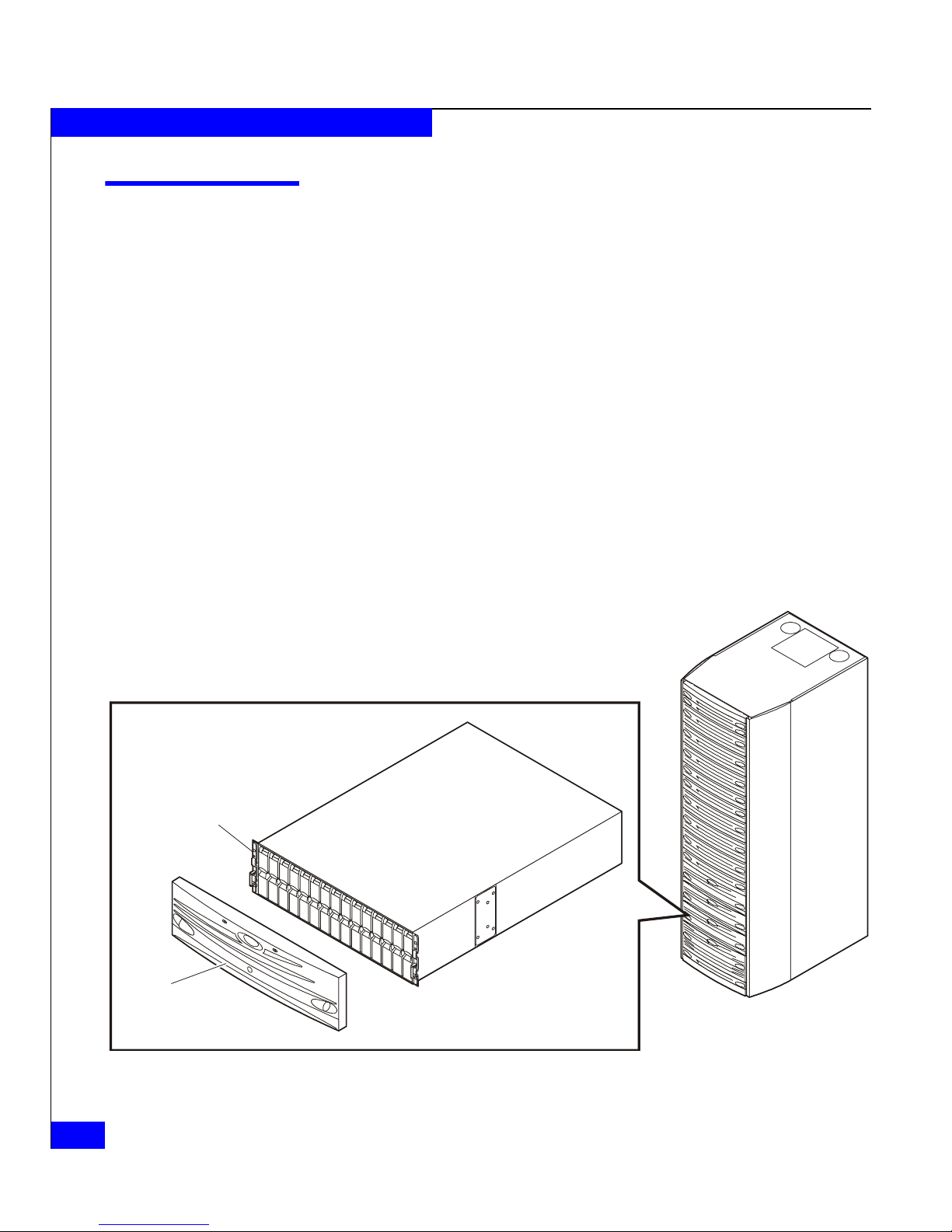
Disk
Drive
(0 - 14)
Front
Bezel
Figure 1-1 DAE2
1-2
2-Gigabit Disk-Array Enclosure (DAE2) Hardware Reference
Rackmount
Cabinet
EMC2164
Page 17

About DAE2 Disk Enclosures
Any DAE2 can support up to fifteen 3.5-inch disk modules. Simple
serial cabling provides easy scalability. You can interconnect DAE2s
to Fibre Channel loops (sometimes called busses) to form a large disk
storage system; the number and size of loops depends on the
capabilities of your storage processor. Highly available
configurations require at least one pair of physically independent
loops (A and B sides of Loop 0, sharing the same dual-port disks).
Other configurations use two, three, or four loops. You can place the
disk enclosures in the same cabinet, or in one or more separate
cabinets. High-availability features are standard.
The DAE2 includes the following components:
◆ A sheet-metal enclosure with a midplane and front bezel
◆ Two link control cards (LCCs)
◆ As many as 15 disk modules
◆ Two power supply/system cooling modules
The power supply and system cooling components of the power/cooling
modules function independently of each other, but the assemblies are
packaged together into a single field-replaceable unit (FRU).
Any unoccupied disk module slot has a filler module to maintain air
flow.
The LCCs, disk modules, power supply/system cooling modules,
and filler modules are field-replaceable units (FRUs), which you can
add or replace without tools while the array is powered up.
Standard DAE2 disk modules are FC-AL compliant and support
dual-port FC-AL interconnects through the two LCCs and their
cabling. ATA disk modules include dual-port ATA interconnects; the
FC-to-ATA link control cards provide the bridge between Fibre
Channel and ATA signals.
You can integrate and connect FC and ATA enclosures within a storage
system, but you cannot mix ATA and fibre components within a DAE2.
Standard link control cards will not recognize ATA disk drives, and ATA link
control cards will not recognize Fibre Channel disks.
The system can continue running with one operating power supply
and a single functional LCC. At least three of the four system cooling
blowers must be running correctly for continuous operation.
Figures 1-2 through 1-4 show the disk enclosure components. Details
on each component accompany the figures. Where the enclosure
Introduction
1-3
Page 18

About DAE2 Disk Enclosures
(
)
provides slots for two identical components, the components are
called component-name A or component-name B, as shown in the
illustrations.
For increased clarity, the following figures depict the disk enclosure outside
of the rack cabinet. Your disk enclosure may be installed in a rackmount
cabinet as shown in Figure 1-1.
As shown in Figure 1-2, the front LED display contains two status
lights for each disk module, and two disk enclosure status lights. The
enclosure status lights are visible with the front bezel installed.
Fault LED
(Amber)
Disk Activity
LED
Green
Figure 1-2 DAE2 Front LED Display
Fault LED
(Amber)
Figure 1-3 shows the DAE2 components visible from the rear of the
enclosure. Each highly-available DAE2 includes two link control
cards and two power supply/system cooling (power/cooling)
modules.
Power LED
(Green)
EMC2166
1-4
2-Gigabit Disk-Array Enclosure (DAE2) Hardware Reference
Page 19
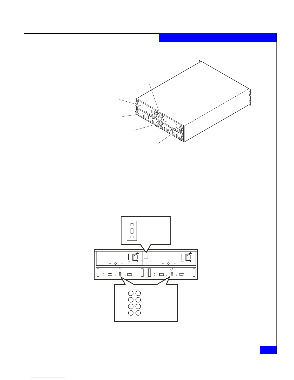
Enclosure
Address
Switch
Power/Cooling
Module B
Link Control
Card B (LCC B)
Power/Cooling
Module A
Link Control
Card A (LCC A)
Figure 1-3 Disk Enclosure Rear View
As shown in Figure 1-3 and Figure 1-4, an enclosure address (EA)
switch/indicator is located between the power supplies at the rear of
the disk enclosure. (The EA is sometimes referred to as an enclosure
ID.) Each link control card (LCC) includes a loop (bus) identification
indicator. The storage processor initializes loop ID when the
operating system loads.
About DAE2 Disk Enclosures
EMC2770
_
Enclosure
0
Address
+
0
1
2
3
Figure 1-4 Disk Enclosure Rear Displays
4
5
6
7
Loop ID
EMC2771
Introduction
1-5
Page 20
About DAE2 Disk Enclosures
The enclosure address is set on the switch at installation. Disk module IDs are
numbered left to right (looking at the front of the unit) and are contiguous
throughout an array: enclosure 0 contains modules 0-14; enclosure 1 contains
modules 15-29; enclosure 2 includes 30-44, and so on through eight
enclosures.
The enclosure EA switch and loop indicator are described in the
installation procedure in Chapter 2. The status lights are described in
the Monitoring Disk Enclosure Status section of Chapter 3.
Midplane
Front Bezel
A midplane between the disk modules and the LCC and
power/cooling modules distributes power and signals to all
components in the enclosure. LCCs, power/cooling modules, and
disk drives — the enclosure’s field-replaceable units (FRUs) — plug
directly into the midplane.
The front bezel, shown in Figure 1-5, has a locking latch and an
electromagnetic interference (EMI) shield. You must remove the bezel
to remove and install drive modules. EMI compliance requires a
properly installed front bezel.
Figure 1-5 Disk Enclosure Front Bezel
1-6
2-Gigabit Disk-Array Enclosure (DAE2) Hardware Reference
EMC2173
Page 21
Link Control Cards (LCCs)
(
)
(
)
An LCC supports and controls one Fibre Channel loop and monitors
the DAE2.
Fault
LED
(Amber)
Power
LED
(Green)
About DAE2 Disk Enclosures
Loop
ID LEDsLatch
Expansion
Connector
Figure 1-6 LCC Connectors and LEDs
Expansion
Link Active
LED
Green
The LCCs in a DAE2 are connected to other Fibre Channel devices
(processor enclosures, DAE2s, and so on) using twin-axial copper
cables. The cabling is not explicitly configured as a loop (with a long
return from the last disk enclosure to the server), but instead, as a set
of full-duplex, point-to-point connections with the last disk enclosure
in the chain closing the loop on its LCC.
The LCC independently receives and electrically terminates the
incoming FC-AL signal. The LCC passes the input signal to the disk
drives in the enclosure; it then sends the output signal, via cables, to
the next DAE2 in the loop. ATA link control cards provide the same
Fibre Channel input and output, but convert those signals to and
from the ATA protocol used by their disk drives.
Each LCC independently monitors the environmental status of the
entire enclosure, using a microcomputer-controlled FRU
(field-replaceable unit) monitor program. The monitor communicates
status to the server, which polls DAE2 status. LCC firmware also
controls the LCC port bypass circuits and the disk-module status
lights.
Primary
Link Active
LED
Green
Primary
Connector
EMC2165
LCCs do not communicate with or control each other.
Each LCC has four status lights. These status lights are described in
Monitoring Disk Enclosure Status in Chapter 3.
Link Control Cards (LCCs)
1-7
Page 22
About DAE2 Disk Enclosures
Disk Modules
A latch on the LCC locks it into place to ensure proper connection to
the midplane. You can add or replace an LCC while the disk
enclosure is powered up.
Each disk module consists of one disk drive in a carrier. You can add
or remove a disk module while the DAE2 is powered up, but should
exercise special care when removing modules while they are in use.
Drive modules are extremely sensitive electronic components. Refer to the
instructions on Handling FRUs and Replacing or Adding a Disk Module in
Chapter 3 whenever you handle a disk module.
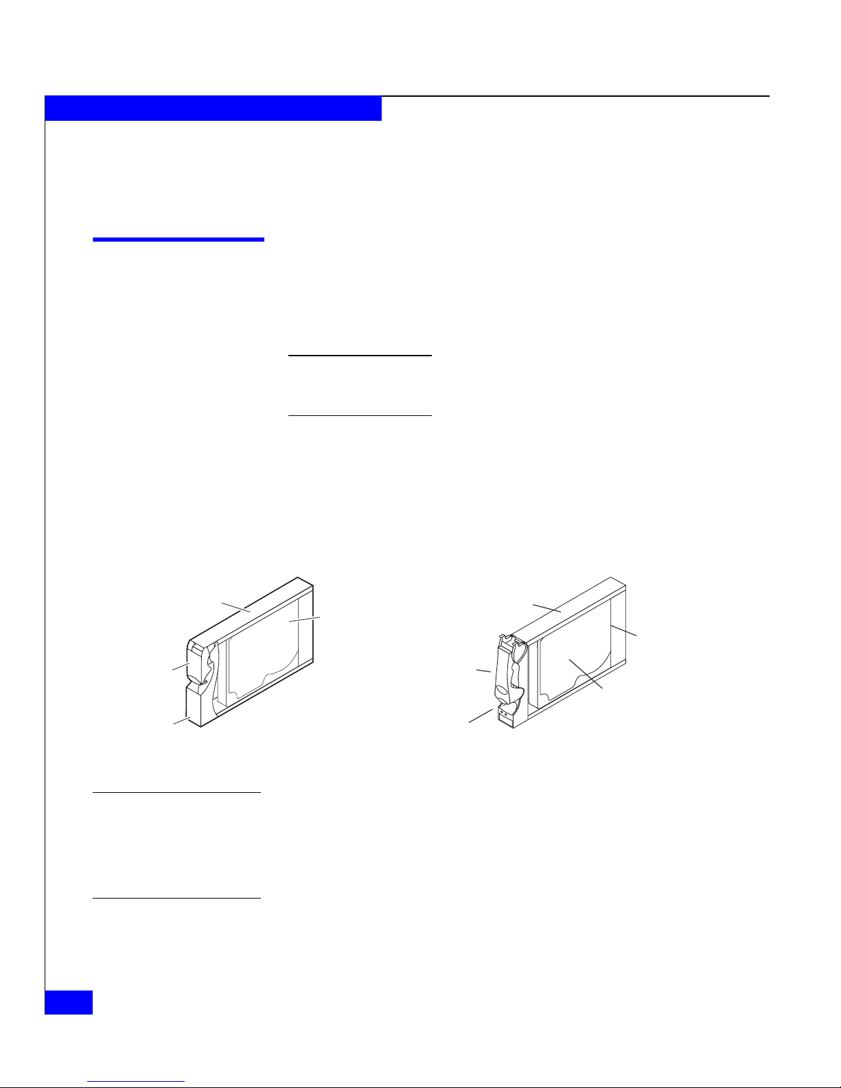
Fibre Channel disk modules will not work in an ATA enclosure, and
vice versa. You can visually distinguish between module types by
their different latch and handle mechanisms. ATA drive modules also
include a small printed-circuit adapter board in the back (connector
side) of the carrier. Figure 1-7 shows the DAE2 disk modules.
Fibre Channel Disk Module
Carrier
Latch
Handle
Figure 1-7 Disk Modules
Disk Drives
Drive Carrier
ATA Disk
Disk
Drive
EMC1758
Latch
Handle
Carrier
Adapter
Board
Disk Drive
EMC2654
DAE2 disk drives conform to either FC-AL or ATA 6 specifications,
and either 1-Gbit and 2-Gbit Fibre Channel or 1.5-Gbit ATA interface
standards. The disk module slots in the enclosure accommodate
1-inch (2.54 cm) by 3.5-inch (8.75 cm) disk drives.
The disk drive carriers are metal and plastic assemblies that provide
smooth, reliable contact with the enclosure slot guides and midplane
connectors. Each carrier has a handle with a latch and spring clips.
1-8
2-Gigabit Disk-Array Enclosure (DAE2) Hardware Reference
Page 23
The latch holds the disk module in place to ensure proper connection
with the midplane. Disk drive Activity/Fault LEDs are integrated
into the carrier.
Power Supply/System Cooling Modules
The power supply/system cooling (power/cooling) modules are
located above the LCCs. The units integrate independent power
supply and dual-blower cooling assemblies into a single module.
Each power supply is an auto-ranging, power-factor-corrected,
multi-output, off-line converter with its own line cord and on/off
switch. Each supply supports a fully configured DAE2 and shares
load currents with the other supply. The drives and LCC have
individual soft-start switches that protect the disk drives and LCCs if
you install them while the disk enclosure is powered up. A FRU
(disk, LCC, or power/cooling module) with power-related faults will
not adversely affect the operation of any other FRU.
About DAE2 Disk Enclosures
The enclosure cooling system includes two dual-blower modules. If
one blower fails, the others will speed up to compensate. If two
blowers in a system (both in one power/cooling module, or one in
each module) fail, the DAE2 will go off line within two minutes.
Each power/cooling module has three visible status lights. The
rightmost LED indicates power to the supply; the LED adjacent to it
indicates a power supply fault. The leftmost LED indicates a failure
in one of the integrated blowers within that module that cool the disk
enclosure. The status lights are shown in Figure 1-8 and described in
Monitoring Disk Enclosure Status in Chapter 3.
Blower Fault
LED
(Amber)
Figure 1-8 Power/Cooling Module
Latch
Power Fault
LED (Amber)
ac
Connector
Power
LED
(Green)
EMC2714
A latch on the power/cooling module locks it into place to ensure
proper connection to the midplane. You can add or remove one
power/cooling module in a DAE2 while the system is powered up.
Power Supply/System Cooling Modules
1-9
Page 24

About DAE2 Disk Enclosures
1-10
2-Gigabit Disk-Array Enclosure (DAE2) Hardware Reference
Page 25

Invisible Body Tag
2
Installing a DAE2
This chapter describes the DAE2 installation requirements and
procedures. Major topics are
◆ Requirements......................................................................................2-2
◆ Installing a Disk Enclosure in a Cabinet.........................................2-3
◆ Setting Up an Installed Disk Enclosure ..........................................2-4
◆ Powerup and Initialization............................................................. 2-12
◆ Binding Disk Modules into RAID Groups ...................................2-13
Installing a DAE2
2-1
Page 26

Installing a DAE2
Requirements
This section explains site and cabling requirements.
Site Requirements
Power To determine a DAE2’s worst case power requirements, use the
Cooling The temperature at the front bezel inlet must meet the ambient
For proper operation, the installation site must conform to certain
environmental specifications. These are detailed below and in
Appendix A.
power rating on the enclosure label. This rating is the maximum
power required for a fully loaded enclosure. The amount of internally
regulated power that a maximum configuration requires from the
power supplies and cooling system determines the values for input
current, power (VA), and dissipation per disk enclosure. Typical
values will be less depending on the number, manufacturer, and type
(FC or ATA) of disk drives. These values represent the sum of the
values shared by the line cords of two power supplies in the same
enclosure. Power cords and supplies share the power load evenly. If
one of the two power supplies fails, the remaining supply and cord
support the full load. You must use a rackmount cabinet with ac
power distribution, and have main branch ac distribution that can
handle these values for the number of disk enclosures that you will
interconnect.
temperature specification described in Appendix A. The site must
have air conditioning that can maintain the specified ambient
temperature range. The air conditioning must be able to handle the
BTU requirements of the DAE2 disk enclosures.
Cabling
Requirements
2-2
2-Gigabit Disk-Array Enclosure (DAE2) Hardware Reference
The DAE2 supports copper cable for a Fibre Channel connection to
another Fibre Channel device (for example, a storage processor or
another DAE2).
Any copper cables you use must meet the appropriate standards for
2-Gbit FC-AL. Such cables are fully shielded, twin-axial, full-duplex
cables with High Speed Serial Data Connector (HSSDC) connectors.
Distances greater than 1 meter require equalized cables; unequalized
one-meter cables are adequate. The DAE2 does not support cables
shorter than 1 meter or longer than 10 meters.
Page 27

EMC supports and can provide 1-, 5-, and 10-meter cables. The 5- and
10-meter cables are equalized.
Interconnections between disk enclosures should maintain LCC
consistency; that is, one Fibre Channel (FC) loop should interconnect
all and only the LCC As, and the other Fibre Channel loop should
interconnect all and only LCC Bs.
Connect all cables at both ends, or remove unused cables completely
from the host or LCC ports. An unused (dangling) cable may cause
excess noise on the loop.
Installing a Disk Enclosure in a Cabinet
Each disk enclosure mounts on two L-shaped rails that connect to the
cabinet’s vertical channels.
◆ The Cabinet Setup Guide for the 40U Cabinet ships with standard
EMC cabinets, and explains how to unpack and install the 40U
cabinet itself.
Installing a DAE2
Warnings and
Recommendations
◆ The EMC Rails and Enclosures Installation Guide for 19-Inch NEMA
Cabinets ships on your hardware documentation CD. It explains
how to install universal mounting rails in the cabinet, and how to
install the enclosure on those rails.
The cabinet in which you will install the disk enclosure(s) must have
a full earth ground to provide reliable grounding. Also, the cabinet
should have its own switchable power distribution. We suggest that
you use a cabinet that has dual power distribution units, one on each
side.
WARNING
The enclosure is heavy and should be installed into a rack by two
people. To avoid personal injury and/or damage to the equipment, do
not attempt to lift and install the enclosure into a rack without a
mechanical lift and/or help from another person.
L’armoire étant lourde, sa mise en place sur une rampe nécessite deux
personnes. Afin de ne pas vous blesser et/ou endommager le matériel,
n’essayez pas de soulever et d’installer l’armoire sur une rampe sans
avoir recours à un relevage mécanique et/ou à l’aide d’une autre
personne.
Installing a Disk Enclosure in a Cabinet
2-3
Page 28

Installing a DAE2
Das Gehäuse ist schwer und sollte nur von zwei Personen in einem
Rack installiert werden. Zur Vermeidung von körperlichen
Verletzungen und/oder der Beschädigung des Gerätes, bitte das
Gehäuse nicht ohne die Hilfe einer zweiten Person anheben und
einbauen.
Il contenitore è pesante e dev'essere installato nel rack da due
persone. Per evitare danni personali e/o all’apparecchiatura, non
tentare di sollevare ed installare in un rack il contenitore senza un
sollevatore meccanico e/o l’aiuto di un’altra persona.
Debido a su considerable peso, la instalación del compartimento en
el bastidor deben realizarla siempre dos personas. Para evitar daños
personales o en el equipo, el compartimento no debe levantarse ni
instalarse en el bastidor sin la ayuda de un elevador mecánico o de
otra persona.
We recommend that you use cabinet anti-tip devices, especially if you
are installing or removing a disk enclosure in the upper half of the
cabinet when the lower half is empty.
Setting Up an Installed Disk Enclosure
Each disk enclosure in a Fibre Channel loop must have a unique
enclosure address (also called an EA, or enclosure ID) that identifies
the enclosure and determines disk module IDs. In many cases, the
factory sets the enclosure address before shipment to coincide with
the rest of the system; you will need to reset the switch if you
installed the enclosure into your rack independently. The enclosure
address ranges from 0 through 7. You set the EA with the enclosure
address switch, which has one push button for incrementing the
address and another for decrementing it. To set the EA, use a tool
such as a pen, paper clip, or small screwdriver.
The enclosure address is set on the EA switch at installation. Disk module IDs
are numbered left to right (facing the unit) and are contiguous throughout an
array: enclosure 0 contains modules 0-14; enclosure 1 contains modules 15-29;
enclosure 2 includes 30-44, and so on through eight enclosures.
2-4
2-Gigabit Disk-Array Enclosure (DAE2) Hardware Reference
Page 29

Installing a DAE2
!
CAUTION
Each drive reads its FC-AL physical address only at powerup or
when the drive is reset. To avoid losing data, you must set the
enclosure address when power is off; you cannot change the EA
while power is on.
1. Set the enclosure address to the desired value, as shown in
Figure 2-1.
_
Enclosure
0
Address
Switch
+
Figure 2-1 Setting the Enclosure Address (EA)
EMC2769
2. If the power/cooling module on the DAE2 includes a power
switch, turn it to the off position before you plug an ac line cord
from the cabinet’s power distribution unit into each
power/cooling module, as shown in Figure 2-2.
Make certain you secure the power cord with the strain reliefs at each
connector. The strain reliefs prevent the power cord from pulling out of
the connections.
Setting Up an Installed Disk Enclosure
2-5
Page 30

Installing a DAE2
ac
Connector
Retention
Bail
EMC2778
Figure 2-2 Plugging in the ac Line Cord
Highly available, write-caching configurations require that you
connect the first disk enclosure (EA 0, loop 0) to a Standby Power
Supply (SPS) for enclosure power. If you do connect a DAE2 to an
SPS (if, for example, the DAE2 is the first disk enclosure in a
CX700-Series or CX600-Series configuration), be sure that you
maintain power/loop integrity; always connect power/cooling
module A to SPS A, and module B to SPS B.
Figure 2-3 shows the power cord connections for a typical
CX700-Series or CX600-Series configuration.
Do not configure an ATA model DAE2 as EA 0, loop 0. ATA enclosures do not
support the boot and SPS requirements of the first disk array in a storage
system.
An integrated disk-and-processor enclosure, such as a CX500, CX400, CX300,
or CX200-Series DPE2, is always the first disk enclosure on the first loop (0,0).
You should not connect the first DAE2 in a DPE2 configuration to an SPS.
2-6
2-Gigabit Disk-Array Enclosure (DAE2) Hardware Reference
Page 31

DAE2
DAE2
Installing a DAE2
Circuit
Breaker
Power
Supply B
SPS B
Power Switch
SPS B
Figure 2-3 Connecting DAE2 Power Cords
3. Repeat steps 1 and 2 for each disk enclosure in the cabinet, as
necessary.
DAE2
DAE2
Power Switch
SPS A
Power
Connector
DAE2
Power
Supply A
SPS A
EMC2780
Setting Up an Installed Disk Enclosure
2-7
Page 32

Installing a DAE2
4. Attach the copper cable from the external device (storage
processor or another DAE2) to the PRI connector as shown in
Figure 2-4. If you are continuing the loop to another DAE2, attach
a cable from the EXP connector to the PRI connector in the next
DAE2.
PRI
Connector
To other FC device
Figure 2-4 Connecting a Disk Enclosure to Another FC Device
5. If you are installing multiple disk enclosures, cable them as
shown in Figure 2-5 or Figure 2-7.
The configuration example in Figure 2-5 shows a CLARiiON
CX500 disk processor enclosure (DPE2) below seven DAE2
disk-array enclosures. The eight devices support two completely
redundant loops. Note that the external device connects to the
Primary disk enclosure connectors, and subsequent enclosures
connect in an Expansion-to-Primary chain.
EA 0, loop 0 must be a Fibre Channel DPE2 or DAE2. ATA enclosures do not
support the boot and SPS requirements of the first disk array in a storage
system.
EMC2772
®
2-8
2-Gigabit Disk-Array Enclosure (DAE2) Hardware Reference
Page 33

LCC B LCC A
EA3/Loop 1
Installing a DAE2
Loop 0
Loop 0
Loop 1
Loop 1
Loop 1
EA3/Loop 0
EA2/Loop 1
EA2/Loop 0
EA1/Loop 1
EA1/Loop 0
Loop 1
Loop 0
Loop 1
Loop 0
Loop 1
EXP EXPPRI PRI
Loop 0 Loop 0
Loop 1
BE 0
Figure 2-5 Cabling Disk Enclosures Together — Two Fibre Channel Loops
BE 1
EA0/Loop 1
EA0/Loop 0
BE 0
Loop 1
BE 1
Setting Up an Installed Disk Enclosure
EMC2720
2-9
Page 34

Installing a DAE2
Loop 3
Figure 2-6 shows a more complicated configuration with eight
DAE2s and four redundant Fibre Channel loops.
EA1/Loop 3
Loop 2
Loop 1
Loop 0
LCC ALCC B
EA1/Loop 2
EA1/Loop 1
Loop 1
EA1/Loop 0
Loop 0
EA0/Loop 3
Loop 3
Loop 2
Loop 3
EA0/Loop 2
Loop 2
EA0/Loop 1
Loop 1
EA0/Loop 0
Loop 0
Loop 0
SP B
SP A
SPS B SPS A
Figure 2-6 Cabling DAE2s Together — Four Fibre Channel Loops
All DAE2 configurations follow the same primary-to-expansion
connection principles. For example, Figure 2-7 shows two
segregated loops connecting contiguous disk enclosures across
two cabinets.
Loop 3
Loop 2
Loop 1
EMC2709
2-10
2-Gigabit Disk-Array Enclosure (DAE2) Hardware Reference
Page 35

DAE2 EA7/Loop 0
Installing a DAE2
LCC ALCC B
Loop 0
Loop 0
Loop 0
Loop 0
Loop 0
Loop 0
Loop 0
Loop 0
DAE2 EA6/Loop 0
DAE2 EA5/Loop 0
DAE2 EA4/Loop 0
DAE2 EA3/Loop 0
DAE2 EA2/Loop 0
DAE2 EA1/Loop 0
DAE2 EA0/Loop 0
Loop 0
Loop 0
Loop 0
Loop 0
Loop 0
Loop 0
Loop 0
Loop 1
Loop 1
Loop 1
Loop 1
Loop 1
Loop 1
LCC B
DAE2 EA7/Loop 1
DAE2 EA6/Loop 1
DAE2 EA5/Loop 1
DAE2 EA4/Loop 1
DAE2 EA3/Loop 1
DAE2 EA2/Loop 1
DAE2 EA1/Loop 1
LCC A
Loop 1
Loop 1
Loop 1
Loop 1
Loop 1
Loop 1
1-Meter
Cable
SP A
SPS B
5- or 10-Meter Cable
SP B
Figure 2-7 Cabling Disk Enclosures Together — Segregated Loop Configuration
6. For proper cooling and normal operation, make sure all the disk
Loop 0
Loop 1
DAE2 EA0/Loop 1
Loop 1
SPS A
EMC1989
module slots in each disk enclosure contain either disk or filler
modules.
Setting Up an Installed Disk Enclosure
2-11
Page 36

Installing a DAE2
7. Set any SPS switches, and then the main circuit breaker switches,
Powerup and Initialization
The only power switches that control most DAE2s are those on the
SPS and the cabinet circuit breakers, which are normally on. If a DAE2
power/cooling module includes a power switch, it is usually on as
well. As a result, a DAE2 is always active.
When you initially apply ac power to a disk enclosure, the disk drive
modules power up according to their specifications, and spin up in a
specified sequence dictated by enclosure and loop IDs. The slot
spin-up delays range from 0 to 84 seconds. The same delays are used
when you insert a drive module while the system is powered up.
Do not power up a disk enclosure without at least one LCC installed.
You can configure a driveless disk enclosure within a Fibre Channel loop.
High availability with write-caching requires disks in slots 0-4 in the first
DPE2 or DAE2 connected to a storage processor (Enclosure Address 0,
loop 0).
to the on position. The disk enclosures in the cabinet power up.
The LCC hardware monitor (FRU monitor) resets and begins its
control loop. The port bypass circuits enter the states indicated by
their associated drives. The monitor continues to run in this local
mode until it receives commands that dictate otherwise. In local
mode, the monitor maintains the port bypass circuits in the same
states as the drive command signals. When a drive fault occurs, the
corresponding drive fault light turns on. Firmware commands can
take control of the port bypass circuits and the drive status lights.
!
CAUTION
Each drive reads its FC-AL physical address only at powerup or
when the drive is reset. To avoid potential data loss, you must set
the enclosure address when you install the disk enclosure and
power is off; you cannot change the EA while power is on.
2-12
2-Gigabit Disk-Array Enclosure (DAE2) Hardware Reference
Page 37

Binding Disk Modules into RAID Groups
After cabling the disk enclosure, use EMC Navisphere® Manager
software to bind the disks into RAID groups. Refer to the EMC
Navisphere Manager Revision 6.X Administrator’s Guide and your
storage processor configuration and planning guide for detailed
information.
Disk Configuration Rules and Recommendations
The following rules and recommendations apply to all CX-Series
systems.
◆ You cannot use disks 000 through 004 (enclosure 0, loop 0, disks
0-4) as a hot spare in a CX-Series system.
◆ On CX-Series systems, the hardware reserves several gigabytes
on each of disks 000 through 004 for the cache vault and internal
tables. To conserve disk space, you should avoid binding any
other disk into a RAID Group that includes any of these disks.
Any disk you include in a RAID Group with a cache disk 000-004
is bound to match the lower unreserved capacity, resulting in lost
storage of several gigabytes per disk.
◆ Each disk in the RAID Group should have the same capacity. All
disks in a Group are bound to match the smallest capacity disk,
and you could waste disk space. The first five drives (000-004)
should always be the same size.
◆ You cannot mix ATA (Advanced Technology Attachment) and
Fibre Channel disk drives within a RAID Group.
◆ Hot spares for Fibre Channel drives must be Fibre Channel
drives; ATA drives require ATA hot spares.
◆ If a storage system will use disks of different speeds (for example,
10K and 15K rpm), then EMC recommends that you use disks of
the same speed throughout each 15-disk enclosure. For any
enclosure, the hardware allows one speed change within an
enclosure, so you may use disks of differing speeds. Place the
higher speed drives in the first (leftmost) drive slot(s).
◆ You should always use disks of the same speed and capacity in
any RAID Group.
◆ Do not use ATA drives to store boot images of an operating
system. You must boot host operating systems from a Fibre
Channel drive.
Installing a DAE2
Binding Disk Modules into RAID Groups
2-13
Page 38

Installing a DAE2
2-14
2-Gigabit Disk-Array Enclosure (DAE2) Hardware Reference
Page 39

Invisible Body Tag nvisible
3
Servicing a DAE2
This chapter describes how to monitor disk enclosure status, handle
FRUs, and replace or add a Field Replaceable Unit (FRU). Topics are
◆ Monitoring Disk Enclosure Status...................................................3-2
◆ Handling FRUs...................................................................................3-6
◆ Replacing or Adding a Disk Module ..............................................3-9
◆ Replacing an LCC Module .............................................................3-15
◆ Replacing a Power Supply/System Cooling Module................. 3-20
For more information about upgrading your DAE2, contact your service
provider.
Servicing a DAE2
3-1
Page 40

Servicing a DAE2
(
)
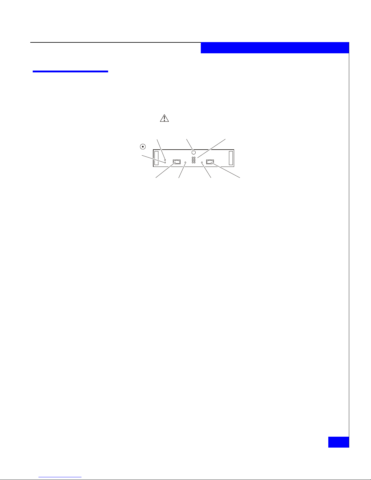
Monitoring Disk Enclosure Status
Status lights on the DAE2 and its FRUs indicate error conditions.
These lights are visible outside the disk enclosure. Some lights are
visible from the front, and the others from the back. Figures 3-1
through 3-4 and Tables 3-1 through 3-3 describe the status lights.
Fault LED
(Amber)
Disk Activity
LED
Green
Figure 3-1 Front Disk Enclosure and Disk Module Status Lights (Bezel Removed)
Fault LED
(Amber)
Power LED
(Green)
EMC2166
Table 3-1 describes the LEDs visible from the front of the DAE2.
3-2
2-Gigabit Disk-Array Enclosure (DAE2) Hardware Reference
Page 41

Servicing a DAE2
Table 3-1 Status Lights Visible from the Front of the Disk Enclosure
Light Quantity Color Meaning
Disk Enclosure Power 1 Green Power to enclosure is on.
Disk Enclosure Fault 1 Amber On when any fault condition exists; if the fault is not obvious
from a disk module light, look at the back of the disk enclosure.
Disk Active 1 per disk module Green Off when the slot is empty or contains a filler module.
Also off when the disk is powered down by command; for
example, the result of a temperature fault.
Flashing
(mostly off)
spinning; this is a normal part of the spin
when the FC drive is powered up but not
-
up sequence,
occurring during the spin-up delay of a slot.
Flashing
(at a constant rate)
FC drive: when the drive is spinning up or spinning down
normally.
ATA drive: when the module has received power but the disk
has not started spinning
On when the drive has power but is not handling any I/O activity
(the ready state). ATA modules also show the Disk Active LED
on while the disk spins up or down normally.
Flashing
(mostly on
) when the drive is spinning and handling I/O
activity.
Flashing (constant fast rate) when an ATA LCC has forced
ownership of the drive.
Disk Fault 1 per disk module Amber On when the disk module is faulty, or as an indication to remove
the drive.
Figure 3-2 shows the enclosure address and loop ID indicators,
visible from the back of the enclosure.
Monitoring Disk Enclosure Status
3-3
Page 42

Servicing a DAE2
_
0
+
Enclosure
Address
0
1
2
3
Figure 3-2 Enclosure Address and Loop ID Indicators
4
5
6
7
Loop ID
EMC2771
Table 3-2 describes the ID indicators.
Table 3-2 Enclosure and Loop ID Indicators
Light Quantity Color Meaning
Enclosure Address 1 Green Displayed number indicates Enclosure Address
Loop ID 8 Green Displayed number indicates Loop ID
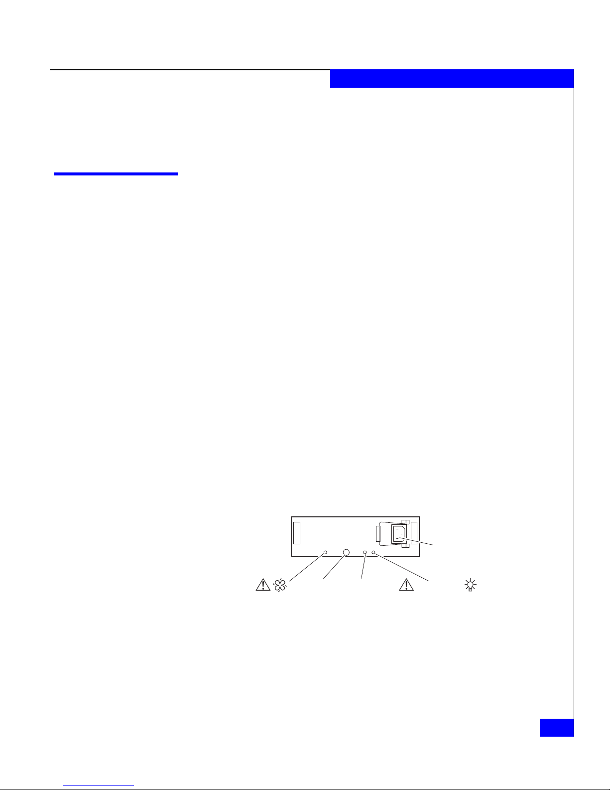
Figure 3-3 shows the status LEDs for the power supply/system
cooling (power/cooling) modules.
Figure 3-3 Power/Cooling Module Status Indicators
3-4
2-Gigabit Disk-Array Enclosure (DAE2) Hardware Reference
Blower Fault
LED
(Amber)
Latch
Power Fault
LED (Amber)
ac
Connector
Power
LED
(Green)
EMC2714
Page 43

Figure 3-4 shows the status LEDs for the link control cards.
(
)
(
)
Fault
LED
(Amber)
Power
LED
(Green)
Loop
ID LEDs
Servicing a DAE2
Expansion
Link Active
LED
Green
Figure 3-4 LCC Status LEDs
Primary
Link Active
LED
Green
EMC2221
Table 3-3 describes the status LEDs visible from the rear of the disk
enclosure.
Table 3-3 Status Lights Visible from the Rear of the Disk Enclosure
Light Quantity Color Meaning
LCC Power 1 per LCC Green On when the LCC is powered up.
LCC Fault 1 per LCC Amber On when either the LCC or a Fibre Channel connection is faulty.
Also on during Power On Self Test (POST).
Primary Link Active 1 per LCC Green On when Primary connection is active.
Expansion Link Active 1 per LCC Green On when Expansion connection is active.
Power Supply Active 1 per supply Green On when the power supply is operating.
Power Supply Fault* 1 per supply Amber On when the power supply is faulty or is not receiving ac line voltage.
Flashing when either a multiple blower or ambient overtemperature
condition have shut off dc power to the system.
Blower Fault* 1 per cooling module Amber On when a single blower in the power supply is faulty.
* The DAE2 will continue running with a single power supply and three of its four blowers. Removing a power/cooling module constitutes a
multiple blower fault condition, and will power down the enclosure unless you replace a blower within two minutes.
If the disk enclosure Fault light is on, examine the other status lights
to determine which FRU(s) is faulty. If a fault light on a FRU remains
on, you should replace that FRU as soon as possible.
Monitoring Disk Enclosure Status
3-5
Page 44

Servicing a DAE2
Handling FRUs
When a redundant FRU fails, high availability will be compromised until you
replace the faulty FRU.
This section describes the precautions that you must take and the
general procedures you must follow when removing, installing, and
storing FRUs.
Power Issues and
FRUs
Avoiding
Electrostatic
Discharge (ESD)
Damage
The DAE2 is designed to always be powered up and hot repairable.
Its front bezel should be attached and each of its compartments
should contain a FRU or filler panel to ensure EMI compliance and
proper air flow over the FRUs.
While the disk enclosure is powered up, you can service or replace
any FRU, although removing an active LCC will affect operating
system access to the disks it controls. You should not remove a faulty
FRU until you have a replacement available.
Since you can replace or add any FRU without sliding the disk
enclosure out of the cabinet, you do not have to use cabinet anti-tip
devices when you upgrade or service a DAE2.
If you need to power down a DAE2, simply unplug the unit. You do
not need to shut down main ac lines to the disk enclosure unless you
need to power down all the cabinet contents connected to that line.
When you replace or install FRUs, you can inadvertently damage the
sensitive electronic circuits in the equipment by simply touching
them. Electrostatic charge that has accumulated on your body
discharges through the circuits. If the air in the work area is very dry,
running a humidifier in the work area will help decrease the risk of
ESD damage. You must follow the procedures below to prevent
damage to the equipment.
3-6
2-Gigabit Disk-Array Enclosure (DAE2) Hardware Reference
Read and understand the following instructions:
◆ Provide enough room to work on the equipment. Clear the work
site of any unnecessary materials or materials that naturally build
up electrostatic charge, such as foam packaging, foam cups,
cellophane wrappers, and similar items.
Page 45

Servicing a DAE2
◆ Do not remove replacement or upgrade FRUs from their antistatic
packaging until you are ready to install them.
◆ Gather together the ESD kit and all other materials you will need
before you service a disk enclosure. Once servicing begins, you
should avoid moving away from the work site; otherwise, you
may build up an electrostatic charge.
◆ An ESD wristband is supplied with your disk enclosure. To use it,
attach the clip of the ESD wristband (strap) to any bare
(unpainted) metal on the disk enclosure; then put the wristband
around your wrist with the metal button against your skin.
◆ Use the ESD kit when handling any FRU. If an emergency arises
and the ESD kit is not available, follow the procedures in the
Emergency Procedures (Without an ESD Kit) section.
Emergency
Procedures (Without
an ESD Kit)
In an emergency when an ESD kit is not available, use the following
procedures to reduce the possibility of an electrostatic discharge by
ensuring that your body and the subassembly are at the same
electrostatic potential.
These procedures are not a substitute for the use of an ESD kit.
Follow them only in the event of an emergency.
◆ Before touching any FRU, touch a bare (unpainted) metal surface
of the cabinet or enclosure.
◆ Before removing any FRU from its antistatic bag, place one hand
firmly on a bare metal surface of the enclosure, and at the same
time, pick up the FRU while it is still sealed in the antistatic bag.
Once you have done this, do not move around the room or touch
other furnishings, personnel, or surfaces until you have installed
the FRU.
◆ When you remove a FRU from the antistatic bag, avoid touching
any electronic components and circuits on it.
◆ If you must move around the room or touch other surfaces before
installing a FRU, first place the FRU back in the antistatic bag.
When you are ready again to install the FRU, repeat these
procedures.
Handling FRUs
3-7
Page 46

Servicing a DAE2
Precautions When
Removing,
Installing, or Storing
FRUs
Use the precautions listed below when you remove, handle, or store
FRUs:
◆ Do not remove a faulty FRU until you have a replacement
available.
◆ Handle a FRU only when using an ESD wristband. Attach the clip
of the ESD wristband to the ESD bracket or bare metal on the
enclosure, and put the wristband around your wrist with the
metal button against your skin.
◆ Handle FRUs gently. A sudden jar, drop, or vibration can
permanently damage a FRU and may not be immediately
evident. Never place a FRU on a hard surface such as an
unpadded cart, floor, or desktop, or stacked on top of another
FRU.
◆ Never use excessive force to remove or install a FRU.
◆ Store a FRU in the antistatic bag and specially designed shipping
container in which you received it. Use that container if you need
to return the FRU for repair.
◆ Store FRUs within the temperature and humidity limits specified
in Appendix A.
◆ Place the cables where no one can step on them or roll equipment
over them.
3-8
2-Gigabit Disk-Array Enclosure (DAE2) Hardware Reference
Page 47

Replacing or Adding a Disk Module
Servicing a DAE2
!
CAUTION
Disk modules are extremely sensitive electronic components.
Always handle a disk module gently, and observe the following
guidelines:
◆ Always replace a disk drive with another of the same model; do
not mix Fibre Channel and ATA components in the same
enclosure. Refer to Figure 1-7 on page 1-8 for a visual
comparison of FC and ATA disk carriers.
◆ Follow the instructions in the preceding section Avoiding
Electrostatic Discharge (ESD) Damage on page 3-6.
◆ Always wear a properly-attached ESD wristband when
removing or replacing a disk module.
◆ When removing a disk module, pull the module partially out of
the slot, then wait 30 seconds for the drive to spin down before
removing it.
◆ Place modules on a soft, antistatic surface, such as an
industry-standard antistatic foam pad or the container used to
ship the module. Never place a disk module directly on a hard
surface.
◆ Never hit modules, stack modules, or allow them to tip over or
fall.
◆ Avoid touching any exposed electronic components and circuits
on the disk module.
◆ Do not remove a faulty disk module until you have a
replacement module (with the same part number) or a filler
module available. The part number (PN005xxxxxx) appears on
the top or bottom of the module. A replacement or add-on disk
module should have the same format (bytes per sector) and the
same capacity (size and speed) as the other modules in the
enclosure.
You must remove the disk enclosure’s front bezel to gain access to the
disk modules. The bezel is required for EMI compliance when the
enclosure is powered up. Remove it only to replace or add a disk
module.
Replacing or Adding a Disk Module
3-9
Page 48

Servicing a DAE2
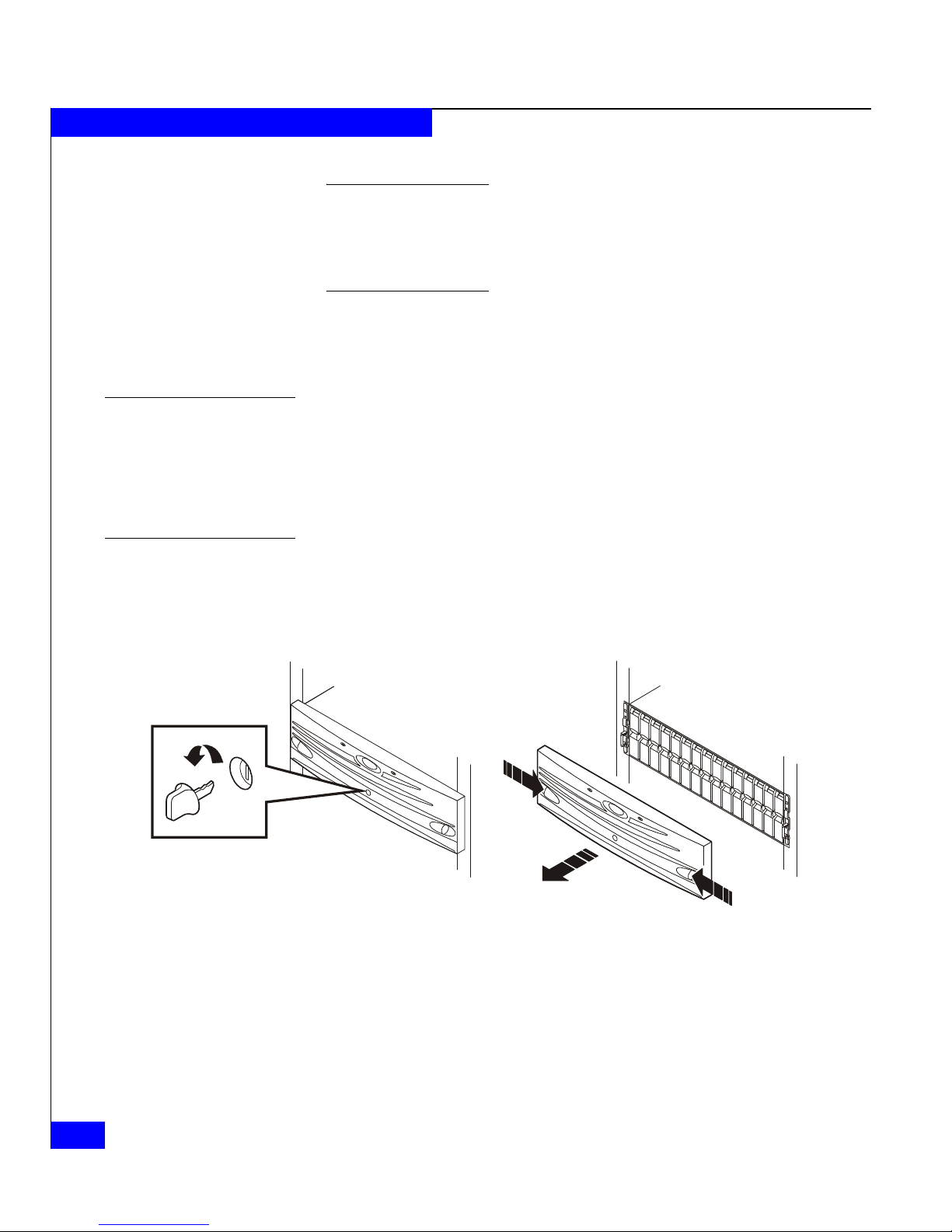
Unlocking and Removing the Front Bezel
Follow these steps to remove the front bezel and gain access to the
disk modules. Refer to Figure 3-5.
1. Insert the key that shipped with your enclosure into the bezel
lock, and turn it to release the lock.
2. Press the two latch buttons on the bezel surface toward each other
to release the bezel from the cabinet.
3. Pull the bezel off the cabinet and put it on a clean, static-free
surface.
3-10
EMC2173
Figure 3-5 Unlocking and Removing the Front Bezel
If you are adding a new disk module, continue to the disk filler
module removal procedure that follows. If you are replacing a faulty
disk module, proceed to the disk module removal procedure.
2-Gigabit Disk-Array Enclosure (DAE2) Hardware Reference
Page 49

Removing a Disk Filler Module
Locate the slot where you want to install the disk module, and
remove the filler module, as shown in Figure 3-6.
Servicing a DAE2
Figure 3-6 Removing a Disk Filler Module (FC Disk Carrier Shown)
Removing a Disk Module
!
EMC2210
Skip to the disk installation procedure (Page 3-12) to install the
add-on disk in the slot you just emptied.
CAUTION
If a disk module has been bound into a LUN, do not move it to
another slot unless you do not care about the data on the LUN. Each
module contains LUN-identifying information written when it was
bound. Moving it to another slot can make information on the
original LUN inaccessible.
Generally, you should not remove a disk module unless its amber
fault light is on. See Table 3-1.
1. Attach an ESD wristband to your wrist and the enclosure (see the
precautions on Page 3-7).
Replacing or Adding a Disk Module
3-11
Page 50

Servicing a DAE2
2. If the active light is on steadily, pull the latch, and slowly pull the
module about 1 in (3 cm) from its slot. Wait 30 seconds for the
disk to stop spinning. Then remove the module and place it on a
padded, static-free surface.
If the active light is off or mostly off you do not need to wait for
the disk to stop spinning. Pull the latch and slowly pull the
module from its slot, as shown in Figure 3-7. Place it on a padded,
static-free surface.
Figure 3-7 Removing a Disk Module (FC Disk Carrier Shown)
Continue to the next section to install the replacement disk module.
Installing a Disk or Filler Module
Always replace a disk drive with another of the same model; do not mix Fibre
Channel and ATA components in the same enclosure. Refer to Figure 1-7 on
page 1-8 for a visual comparison of FC and ATA disk carriers.
1. Make sure an ESD wristband is attached to your wrist and the
enclosure (see the precautions on Page 3-7).
2. Align the module with the guides in the slot.
3. Gently push the module completely into the slot, and then engage
the latch. See Figure 3-8.
EMC2174
3-12
2-Gigabit Disk-Array Enclosure (DAE2) Hardware Reference
Page 51

EMC2211
Figure 3-8 Installing a Disk or Filler Module (FC Disk Carrier Shown)
The disk module’s Active light flashes to reflect the disk’s spin-up
sequence.
Servicing a DAE2
4. Remove and store the ESD wristband and continue to the next
section to install the front bezel.
Replacing or Adding a Disk Module
3-13
Page 52

Servicing a DAE2
Installing and Locking the Front Bezel
Refer to Figure 3-9 as you do the following:
1. Align the bezel with the disk enclosure.
2. Gently push the bezel into place on the cabinet until it latches.
3. Secure the bezel by turning the key in the lock.
Figure 3-9 Installing and Locking the Front Bezel
EMC2222
3-14
2-Gigabit Disk-Array Enclosure (DAE2) Hardware Reference
Page 53

Replacing an LCC Module
Servicing a DAE2
Removing an LCC
!
CAUTION
Handle an LCC gently and use an ESD wristband. Do not remove a
faulty LCC until you have a replacement module available.
A DAE2 must have at least one LCC installed while it is powered up. Do not
remove both LCCs while the disk enclosure is powered up.
Always replace an LCC with another of the same model; do not mix Fibre
Channel and ATA components in the same enclosure. (An "ATA Ctlr" label on
the module bulkhead identifies the ATA LCC.)
1. Gently press the connector latches to release them as you remove
the copper cables connected to the LCC, as shown in Figure 3-10.
Note where the cable(s) connect to the LCC; you will need to reconnect
them to the replacement LCC.
To other FC device
Figure 3-10 Removing a Copper Cable from an LCC
PRI
Connector
EMC2782
Replacing an LCC Module
3-15
Page 54

Servicing a DAE2
2. Turn the latch counterclockwise to release the module, and then
remove the LCC from its slot, as shown in Figure 3-11.
Figure 3-11 Removing an LCC
Installing an LCC
Latch
EMC2774
Continue to the next section to install the replacement LCC.
1. Gently insert the LCC as shown in Figure 3-12. Be sure the module
is completely seated in the DAE2 midplane.
3-16
2-Gigabit Disk-Array Enclosure (DAE2) Hardware Reference
Page 55

Servicing a DAE2
Latch
Figure 3-12 Installing an LCC
The LCC Power light turns on.
2. Turn the latch clockwise to secure the module.
The DAE2 LCC latch holds the module in an established position. It does
not pull or otherwise help to seat the LCC.
3. Reattach the copper cables to the same connector from which you
removed them, as shown in Figure 3-13.
EMC2776
Replacing an LCC Module
3-17
Page 56

Servicing a DAE2
PRI
Connector
To other FC device
EMC2772
Figure 3-13 Reconnecting a Copper Cable to an LCC
4. Remove and store the ESD wristband.
The configuration example in Figure 3-14 shows a CLARiiON® CX300 disk
processor enclosure (DPE2) below three DAE2 disk-array enclosures. Note
that the external device connects to the Primary disk enclosure connectors,
and subsequent enclosures connect in an Expansion-to-Primary chain.
3-18
2-Gigabit Disk-Array Enclosure (DAE2) Hardware Reference
Page 57

LCC B LCC A
EA3/Loop 0
Servicing a DAE2
EA2/Loop 0
Loop 0 Loop 0
EA1/Loop 0
EXP EXPPRI PRI
Loop 0 Loop 0
EA0/Loop 0
BE 0
BE 0
Figure 3-14 Connecting Disk Enclosures Together with Copper Cable
Loop 0Loop 0
EMC2743
Replacing an LCC Module
3-19
Page 58

Servicing a DAE2
Replacing a Power Supply/System Cooling Module
!
CAUTION
Handle a power supply/system cooling (power/cooling) module
gently and use an ESD wristband. Do not remove a power/cooling
module until you have a replacement module available.
Access to the disks in your enclosure will time out and the disks
will spin down two minutes after a power/cooling module is
removed from the enclosure. While the system can continue
operating on a single power supply, the loss of a module’s two
blowers will cause a time-out unless you replace the module within
two minutes.
When replacing a power/cooling module, make certain the green
LED on one module has been steadily on for at least 5 seconds
before removing power from the second module.
Turn any power/cooling module switch to the off position before
unplugging the power cord from the module.
Follow these steps to replace a power/cooling module.
1. Turn off the power/cooling module (if a switch is present) and
unplug its ac line cord as shown in Figure 3-15.
3-20
ac
Connector
Retention
Bail
EMC2775
Figure 3-15 Unplugging the ac Power Cord
2-Gigabit Disk-Array Enclosure (DAE2) Hardware Reference
Page 59

Servicing a DAE2
2. Turn the latch counterclockwise to release the module, and then
remove the power/cooling module as shown in Figure 3-16.
To protect a running system from overheating, the enclosure will time
out unless you replace the power/cooling module within two minutes.
Latch
Figure 3-16 Removing a Power/Cooling Module
3. Gently insert the new power/cooling module into the enclosure,
as shown in Figure 3-17. Be sure the module is completely seated.
Latch
EMC2773
Figure 3-17 Installing a Power/Cooling Module
EMC2777
Replacing a Power Supply/System Cooling Module
3-21
Page 60

Servicing a DAE2
4. Turn the latch clockwise to secure the module.
The latch holds the power/cooling module in an established position. It
does not pull or otherwise help to seat the module.
5. Make sure any power switch on the replacement module is off
before you plug the ac power cord into the new supply as shown
in Figure 3-18. Turn a power switch to the on position after you
plug in the ac power cord.
ac
Connector
Figure 3-18 Plugging in the Power Cord
Make certain you secure the power cord with the retention bails at each
connector. The bails prevent the power cord from pulling out of the
connections.
Retention
Bail
EMC2778
3-22
2-Gigabit Disk-Array Enclosure (DAE2) Hardware Reference
Page 61

Invisible Body Tag
A
Technical
Specifications
Body Tag
This appendix describes the disk-array enclosure technical
specifications, operating limits, and shipping and storage
requirements. Major topics are
◆ Enclosure Specifications...................................................................A-2
◆ Operating Limits...............................................................................A-5
Technical Specifications
A-1
Page 62

Technical Specifications
Enclosure Specifications
Technical enclosure specifications include power requirements, size,
drive, interface, and standards information.
Ac Power
Requirements
Requirement DAE2 (Fibre Channel) DAE2-ATA
ac line voltage 100 to 240 V ac + 10%, single phase, 47 to 63 Hz
ac line current 4.0 A at 100 V ac, 1.6 A at 200 V ac 3.0 A at 100 Vac, 1.4 A at 200 V ac
The input current, power (VA), and dissipation per DAE2 are based
on the requirements that a maximum DAE2 configuration places on
the power supplies and cooling system to provide internal regulated
power. Typical values will be less, depending on the number and
manufacturer of disk modules. These values represent either
◆ the values for a single power supply line cord, or
◆ the sum of values shared by the line cords of two power supplies
in the same DAE2, with the division between the line cords and
supplies at the current sharing ratio (approximately 50% each).
A failure of one of the two power supplies in the DAE2 results in the
remaining supply and cord supporting the full load. You must use a
rackmount cabinet with ac power distribution, and have main branch
ac distribution that can handle these values for each disk enclosure in
the cabinet.
Description
Power consumption 400 VA(392 W) max (fully configured)* 300 VA (294 W) max (fully configured)*
Power factor 0.98 min at full load, low voltage
Heat dissipation 1.41 x10
In-rush current 25 A max for 1/2 line cycle, per power supply at 240 V ac
Startup surge current 15 A pk (10.6 A rms) max for 100 ms, at any line voltage
ac protection 10 A fuse in each power supply, both phases
ac receptacle type IEC320-C14 appliance coupler, per power supply
Ride-through time 30 ms min
Current sharing 60% max, 40% min, between power supplies
A-2
2-Gigabit Disk-Array Enclosure (DAE2) Hardware Reference
6
J/hr (1,330 BTU/hr) max * 1.06 x10⁶ J/hr (1,017 BTU/hr) max *
15 A max for 1/2 line cycle, per power supply at 120 V ac
*A fully configured DAE2 includes two power supplies, two LCCs, and 15 disk drives.
Page 63

Size and Weight
Technical Specifications
Requirement Measurement
Height 133.35 mm (5.25 in)
3 NEMA units including mounting hardware
Width 450 mm (17.72 in)
Depth 603.25 mm (23.75 in)
Weight 43.2 kg (95.3 lbs) maximum configuration
1.1 kg (2.4 lbs) per FC disk module;
1.125 kg (2.5 lbs) per ATA module
1.4 kg (3 lbs) per link control card
4.1 kg (9 lbs) per power supply
12.7 kg (28 lbs) chassis and midplane
Drive Type
LCC FC-AL Interface
Copper Cabling
The DAE2 uses 3.5-inch (8.75 cm) by 1.0-inch (2.54 cm) disk drives.
Standard, Fibre Channel versions are 12-volt, and support the Fibre
Channel interface. ATA versions are 12- and 5-volt and support the
ATA-6 interface.
Each drive slot provides an average maximum of 16 W drive module
power.
Refer to the EMC Storage Systems CX-Series Disk and FLARE OE Matrix
for a list of supported drives.
Connectors are shielded HSSDC (High Speed Serial Data Connector).
Type: Shielded, 150 Ω differential, shield bonded to HSSDC plug connector
°
shell (360
FC-PI Standard, Revision 13 or higher
Length: 1 meter (3.3 feet) unequalized;
5 meter (16.5 feet) and 10 meter (33 feet) equalized
)
Enclosure Specifications
A-3
Page 64

Technical Specifications
Standards Certification and Compliance
Rackmount disk enclosures are tested and certified for compliance
with the international environmental and safety specifications listed
below and marked to indicate such compliance and certification as
required.
Standard Description
CSA 22.2 No. 950
EN 60950
UL 1950
CE Mark European EMC Directive & Low Voltage Directive Requirements
NEBS/Bellcore* NEBS: Level 3 compliant, Physical Protection, EMC and Safety
* Standard DAE2. DAE2-ATA not tested for NEBS/Bellcore compliance.
Safety of Information Technology Equipment including Electrical
Business Equipment
Bellcore: GR-63-CORE, GR-1089-CORE, SR-3580
EMI Standards
Standard Description
FCC Part 15 Class A, Radio Frequency Device Requirements
ICES-003 Class A, Interference-Causing Equipments Standard - Digital
CE Mark European EMC Directive & Low Voltage Directive Requirements.
VCCI Class A, Voluntary Control Council for Interference
AS/NZS CISPR22 Class A, Electromagnetic Interference - Limits & Methods of
CNS13438 BSMI EMC Requirements
Fibre Channel Related Standards
Standard Description
Fibre Channel Physical and signaling interface, FC-PI, draft Rev. 13
Fibre Channel Arbitrated Loop (FC-AL), Revision 4.5
Apparatus
Measurement of ITE
A-4
2-Gigabit Disk-Array Enclosure (DAE2) Hardware Reference
Fibre Channel Private Loop Direct Attach (PLDA), Revision 2.1
In some cases, the DAE2 uses functions from later revisions of specifications.
Page 65

Operating Limits
Technical Specifications
The ambient temperature specification is measured at the front bezel
inlet. The site must have air conditioning of the correct size and
placement to maintain the specified ambient temperature range. The
air conditioning must be able to handle the heat dissipation
requirements of the disk enclosures.
Requirement Description
o
Ambient temperature 10
Temperature gradient 10oC/hr (18oF/hr)
Relative humidity 20% to 80% noncondensing
Elevation 2438 m (8,000 ft) at 40
C to 40oC (50oF to 104oF)
o
C, 3077 m (10,000 ft) at 37oC
Environmental Recovery
The operating limits for temperature and humidity must not be exceeded
inside the closed cabinet in which the
equipment in a cabinet directly above or below a
flow to the disk enclosure, because air flows through the enclosure from front
to back. Cabinet doors must not impede the front-to-back air flow.
DAE2s are mounted. Mounting
DAE2 does not restrict air
If the system exceeds maximum ambient temperature by
approximately 10°C/18°F, the storage processors will begin an
orderly shutdown that saves cached data, shuts off the SPs, and — in
a DPE2 enclosure — powers down the disks. LCCs in each DAE2 will
power down their disks but remain powered on. If the system detects
that the temperature has dropped to an acceptable level, it restores
power to the storage processors (which power up any disks in their
enclosure), and the LCCs restore power to their disk drives.
Operating Limits
A-5
Page 66

Technical Specifications
Shipping and Storage Requirements
Requirement Description
Ambient temperature -40
Temperature gradient 25
Relative humidity 10% to 90% noncondensing
Elevation 7625 m (25,000 ft)
o
C to 65oC (-40oF to 149oF)
o
C/hr (45oF/hr)
A-6
2-Gigabit Disk-Array Enclosure (DAE2) Hardware Reference
Page 67

nvisible Body Tag
B
Customer Support
This appendix reviews the EMC process for detecting and resolving
software problems, and provides essential questions that you should
answer before contacting the EMC Customer Support Center.
This appendix covers the following topics:
◆ Overview of Detecting and Resolving Problems ......................... B-2
◆ Troubleshooting the Problem.......................................................... B-3
◆ Before Calling the Customer Support Center............................... B-4
◆ Documenting the Problem............................................................... B-5
◆ Reporting a New Problem............................................................... B-6
◆ Sending Problem Documentation................................................... B-7
Customer Support
B-1
Page 68

Customer Support
Overview of Detecting and Resolving Problems
EMC software products are supported directly by the EMC Customer
Support Center in the United States.
EMC uses the following process to resolve customer problems with
its software products (Figure B-1).
Problem
Detection
Refer to this
Customer Support
Appendix for Instructions
Collect Problem
Information as
Directed
Contact the EMC Customer
Support Center:
U.S.:
Canada:
Worldwide:
(800) SVC-4EMC
(800) 543-4SVC
(508) 497-7901
Confirm that the
Problem is Software
Related
Call will be Directed
to an EMC Software
Support Engineer
Problem is
Tracked and
Managed to
Resolution
Figure B-1 Problem Detection and Resolution Process
B-2
2-Gigabit Disk-Array Enclosure (DAE2) Hardware Reference
Page 69

Troubleshooting the Problem
Please perform the relevant diagnostic steps before you contact the
EMC Customer Support Center:
1. Read the documentation carefully.
2. Reconstruct the events leading up to the problem and describe
them in writing.
3. Run some test cases to reproduce the problem.
If you encounter a problem that requires technical programming or
analysis, call the nearest EMC office or contact the EMC Customer
Support Center at one of the following numbers:
United States: (800) 782-4362 (SVC-4EMC)
Canada: (800) 543-4782 (543-4SVC)
Wo rl dw id e: (508) 497-7901
Customer Support
Please do not request a specific support representative unless one has already
been assigned to your particular system problem.
For additional information on EMC products and services available
to customers and partners, refer to the EMC Powerlink website at:
http://powerlink.EMC.com
Troubleshooting the Problem
B-3
Page 70

Customer Support
Before Calling the Customer Support Center
Have the following information available before calling the Customer
Support Center or your support representative (if one has been
assigned to you):
❑ Your company name
❑ Your name
❑ Your phone number
❑ For an existing problem, the problem tracking system ID, if one
was previously assigned to the problem by a support
representative
❑ For an MVS problem, the JESLOG, SYSPRINT, all STDOUT DD
members of the server job output and similar output for the
client, and the relevant portion of the SYSLOG
B-4
2-Gigabit Disk-Array Enclosure (DAE2) Hardware Reference
Page 71

Documenting the Problem
If the EMC Customer Support Center requests information regarding
the problem, please document it completely, making sure to include
the following information:
❑ Your company name and address
❑ Your name
❑ Your telephone number
❑ The importance of the problem, so that it can be assigned a
priority level
To expedite the processing of your support request, you can
photocopy this list and include it with the package.
Customer Support
Documenting the Problem
B-5
Page 72

Customer Support
Reporting a New Problem
For a new problem, please provide the following information:
❑ Release level of the software that you are running
❑ Software installation parameters
❑ Host type on which you are running
❑ Operating system you are running and its release number
❑ Functions of the software that you are running
❑ Whether you can reproduce the problem
❑ Previous occurrences of the problem
❑ Whether the software has ever worked correctly
❑ Time period that the software did work properly
❑ Conditions under which the software worked properly
❑ Changes to your system between the time the software worked
properly and the problem began
❑ Exact sequence of events that led to the system error
❑ Message numbers and complete text of any messages that the
system produced
❑ Log file dated near the time the error occurred
❑ Results from tests that you have run
❑ Other related system output
❑ Other information that may help solve the problem
B-6
2-Gigabit Disk-Array Enclosure (DAE2) Hardware Reference
Page 73

Sending Problem Documentation
Use one of the following methods to send documentation of the
problem to the EMC Customer Support Center:
◆ E-mail
◆ FTP
◆ U.S. mail to the following address:
EMC Customer Support Center
45 South Street
Hopkinton, MA 01748-9103
If the problem was assigned a number or a specific support
representative, please include that information in the address as
well.
Customer Support
Sending Problem Documentation
B-7
Page 74

Customer Support
B-8
2-Gigabit Disk-Array Enclosure (DAE2) Hardware Reference
Page 75

Index
A
ac power cord
attaching to power supply 3-22
removing from power supply 3-20
ac power, current draw A-2
Active light
LCC 3-5
power supply 3-5
adding
disk module 3-9
LCC 3-15
power supply 3-20
ATA disks, configuration rules 2-13
B
battery, disposing of safely xiv
binding RAID groups 2-13
C
cabinet, installing DAE2 in 2-3
cables
attaching DAE2 to DAE2 with 3-19
reattaching to LCC 3-18
removing from LCC 3-15
requirements 2-2
cabling
precautions 3-8
requirements 2-2
chassis see enclosure
check light
DAE2 components 3-2
LCC 3-5
power supply 3-5
comments xii
components 1-3
Cooling Check light 3-5
current draw, DAE2 A-2
customer support xii, B-3
Customer Support Center B-7
D
DAE2 (2-gigabit disk-array enclosure)
disk module
description 1-8
disk drive 1-8
drive carrier 1-8
EA indicator 3-4
front bezel, description 1-6
operating limits A-5
power supply 1-9
powering down 3-6, 3-20
powering up 3-22
rear 1-5
requirements, operating A-5
technical specifications A-2
disk configuration rules 2-13
disk drive
description 1-8
specifications A-3
2-Gigabit Disk-Array Enclosure (DAE2) Hardware Reference
i-1
Page 76

Index
disk module
adding 3-9
binding into RAID groups 2-13
description 1-8
disk drive 1-8
drive carrier 1-8
drive specifications A-3
replacing 3-9
disks, configuration rules 2-13
documentation, related x
drive carrier description 1-8
E
EA (enclosure address)
indicator 3-4
requirements 2-4
setting 2-5
EA indicator 3-4
electromagnetic interference (EMI)
shield 1-6
standards certification/compliance A-4
electrostatic discharge (ESD), avoiding 3-6
enclosure
description 1-3
EA indicator 3-4
midplane description 1-6
rear, description 1-5
Enclosure Address (EA)
requirements 2-4
setting 2-5
Enclosure ID see Enclosure Address
environmental recovery A-5
F
FC-AL (Fibre Channel Arbitrated Loop)
cabling A-3
requirements 2-2
connector A-3
interface specifications A-3
physical address 2-4
Fibre Channel, related standards A-4
front bezel
description 1-6
unlocking and removing 3-10
FRUs (field-replaceable units)
defined 1-3
disk module
adding 3-9
description 1-8
removing 3-11
replacing 3-9
handling 3-6
LCC
adding 3-15
description 1-7
replacing 3-15
power issues 3-6
power supply
adding 3-20
description 1-9
replacing 3-20
storing 3-6
H
help xii
hot spare, restrictions 2-13
I
indicators, ID 3-4
installation requirements 2-2
installing
DAE2 in cabinet 2-3
disk filler modules 3-12
L
LCC (link control card)
adding 3-15
cabling A-3
DAE2 to DAE2 3-19
requirements 2-2
description 1-7
FC-AL connector A-3
reattaching cables to 3-18
removing copper cables 3-15
replacing 3-15
status light, Active 3-5
status lights 1-7
lights, DAE2 status 3-2
lithium backup battery, disposing of safely xiv
i-2
2-Gigabit Disk-Array Enclosure (DAE2) Hardware Reference
Page 77

Index
M
midplane 1-6
monitoring 3-2
N
NEBS compliance A-4
O
overtemperature recovery A-5
P
power
issues and FRUs 3-6
overview 2-2
power supply
adding 3-20
attaching ac power cord 3-22
description 1-9
removing
ac power cord 3-20
replacing 3-20
status lights
Active 3-5
Check 3-5
Cooling Check 3-5
turning off 3-20
turning on 3-22
powering down DAE2 3-6, 3-20
powering up DAE2 3-22
power-up and initialization sequence 2-12
R
RAID groups 2-13
rear, description 1-5
recovery, environmental A-5
removing, disk module 3-11
replacing
disk module 3-9
LCC 3-15
power supply 3-20
requirements, cabling 2-2
S
service xii
shipping requirements A-6
site requirements 2-2
specifications, DAE2 A-2
status, monitoring DAE2 3-2
status lights, DAE2 3-2
T
technical specifications, DAE2 A-2
Technical support xii, B-3
turning off power supply 3-6, 3-20
turning on power supply 3-22
V
voltage, DAE2 requirements A-2
2-Gigabit Disk-Array Enclosure (DAE2) Hardware Reference
i-3
Page 78

Index
i-4
2-Gigabit Disk-Array Enclosure (DAE2) Hardware Reference
 Loading...