

Dell CJWTV Service Manual

Dell Vostro 3580
Service Manual
Regulatory Model: P75F
Regulatory Type: P75F010

Notes, cautions, and warnings
NOTE: A NOTE indicates important information that helps you make better use of your product.
CAUTION: A CAUTION indicates either potential damage to hardware or loss of data and tells you how to avoid the problem.
WARNING: A WARNING indicates a potential for property damage, personal injury, or death.
© 2019 Dell Inc. or its subsidiaries. All rights reserved. Dell, EMC, and other trademarks are trademarks of Dell Inc. or its subsidiaries. Other trademarks
may be trademarks of their respective owners.
2019 - 01
Rev. A00

Contents
1 Working on your computer............................................................................................................................. 6
Safety instructions.............................................................................................................................................................6
Turning o your computer — Windows 10.....................................................................................................................6
Before working inside your computer.............................................................................................................................. 7
After working inside your computer.................................................................................................................................7
2 Technology and components..........................................................................................................................8
DDR4................................................................................................................................................................................... 8
DDR4 Details.................................................................................................................................................................8
Memory Errors..............................................................................................................................................................9
HDMI 1.4..............................................................................................................................................................................9
HDMI 1.4 Features........................................................................................................................................................9
Advantages of HDMI..................................................................................................................................................10
USB features.....................................................................................................................................................................10
USB 3.0/USB 3.1 Gen 1 (SuperSpeed USB)............................................................................................................10
Speed............................................................................................................................................................................ 11
Applications.................................................................................................................................................................. 11
Compatibility................................................................................................................................................................12
Intel Optane memory........................................................................................................................................................12
Enabling Intel Optane memory..................................................................................................................................12
Disabling Intel Optane memory................................................................................................................................. 13
3 Removing and installing components............................................................................................................14
Recommended tools.........................................................................................................................................................14
Screw list........................................................................................................................................................................... 14
Micro Secure Digital Card................................................................................................................................................ 15
Removing the Micro Secure Digital Card.................................................................................................................15
Installing the Micro Secure Digital Card................................................................................................................... 15
Optical drive assembly..................................................................................................................................................... 16
Removing the optical drive assembly.......................................................................................................................16
Installing the optical drive assembly......................................................................................................................... 17
Base cover.........................................................................................................................................................................18
Removing the base cover..........................................................................................................................................18
Installing the base cover............................................................................................................................................20
Battery............................................................................................................................................................................... 21
Lithium-ion battery precautions................................................................................................................................ 21
Removing the battery................................................................................................................................................22
Installing the battery..................................................................................................................................................22
Memory modules..............................................................................................................................................................23
Removing the memory module................................................................................................................................ 23
Installing the memory module...................................................................................................................................24
WLAN card....................................................................................................................................................................... 25
Removing the WLAN card........................................................................................................................................25
Contents
3

Installing the WLAN card.......................................................................................................................................... 26
Solid-state drive/Intel Optane memory module........................................................................................................... 27
Removing the M.2 2230 Solid-state drive.............................................................................................................. 27
Installing the M.2 2230 Solid-state drive................................................................................................................ 28
Removing the M.2 2280 Solid-state drive or Intel Optane memory - Optional................................................. 30
Installing the M.2 2280 Solid-state drive or Intel Optane memory - Optional....................................................30
Coin-cell battery................................................................................................................................................................31
Removing the coin-cell...............................................................................................................................................31
Installing the coin-cell battery...................................................................................................................................32
Hard drive..........................................................................................................................................................................33
Removing the hard drive assembly..........................................................................................................................33
Installing the hard drive assembly............................................................................................................................35
System fan........................................................................................................................................................................37
Removing the system fan......................................................................................................................................... 37
Installing the system fan............................................................................................................................................39
Heat sink............................................................................................................................................................................ 41
Removing the heatsink...............................................................................................................................................41
Installing the heatsink................................................................................................................................................ 42
VGA Daughterboard........................................................................................................................................................ 42
Removing the VGAcable...........................................................................................................................................42
Installing the VGA cable............................................................................................................................................ 43
Speakers............................................................................................................................................................................44
Removing the speakers.............................................................................................................................................44
Installing the speakers............................................................................................................................................... 45
IO board.............................................................................................................................................................................46
Removing the IO board............................................................................................................................................. 46
Installing the IO board................................................................................................................................................48
Touchpad...........................................................................................................................................................................49
Removing the touch pad assembly..........................................................................................................................49
Installing the touch pad assembly.............................................................................................................................51
Display assembly.............................................................................................................................................................. 53
Removing the display assembly............................................................................................................................... 53
Installing the display assembly..................................................................................................................................56
Power-button board........................................................................................................................................................ 59
Removing the power button board..........................................................................................................................59
Installing the power button board............................................................................................................................ 60
System board.................................................................................................................................................................... 61
Removing the system board......................................................................................................................................61
Installing the system board....................................................................................................................................... 65
Power button with ngerprint reader............................................................................................................................68
Removing the power button with ngerprint reader.............................................................................................68
Installing the power button with ngerprint reader...............................................................................................69
Power-adapter port......................................................................................................................................................... 70
Removing the power adapter port...........................................................................................................................70
Installing the power adapter port..............................................................................................................................71
Display bezel......................................................................................................................................................................72
Removing the display bezel.......................................................................................................................................72
Contents
4

Installing the display bezel ........................................................................................................................................ 73
Camera.............................................................................................................................................................................. 74
Removing the camera................................................................................................................................................74
Installing the camera..................................................................................................................................................75
Display panel..................................................................................................................................................................... 76
Removing the display panel...................................................................................................................................... 76
Installation display panel............................................................................................................................................ 78
Display hinges...................................................................................................................................................................80
Removing the display hinges....................................................................................................................................80
Installing the display hinges....................................................................................................................................... 81
Display cable..................................................................................................................................................................... 82
Removing the display cable...................................................................................................................................... 83
Installing the display cable.........................................................................................................................................84
Display back-cover and antenna assembly................................................................................................................... 85
Removing the display back-cover............................................................................................................................85
Installing the display back-cover...............................................................................................................................87
Palm-rest and keyboard assembly................................................................................................................................. 88
Removing the palmrest and keyboard assembly....................................................................................................88
4 Troubleshooting........................................................................................................................................... 90
Enhanced Pre-Boot System Assessment (ePSA) diagnostics...................................................................................90
Running the ePSA diagnostics.................................................................................................................................90
System diagnostic lights................................................................................................................................................. 90
Flashing BIOS (USB key)................................................................................................................................................. 91
Flashing the BIOS............................................................................................................................................................ 92
Backup media and recovery options..............................................................................................................................92
WiFi power cycle..............................................................................................................................................................92
Flea power release...........................................................................................................................................................92
5 Getting help.................................................................................................................................................93
Contacting Dell.................................................................................................................................................................93
Contents
5

Working on your computer
Safety instructions
Prerequisite
Use the following safety guidelines to protect your computer from potential damage and to ensure your personal safety. Unless otherwise
noted, each procedure included in this document assumes that the following conditions exist:
• You have read the safety information that shipped with your computer.
• A component can be replaced or, if purchased separately, installed by performing the removal procedure in reverse order.
About this task
WARNING: Disconnect all power sources before opening the computer cover or panels. After you nish working inside the
computer, replace all covers, panels, and screws before connecting to the power source.
WARNING: Before working inside your computer, read the safety information that shipped with your computer. For additional
safety best practices information, see the Regulatory Compliance Homepage
CAUTION: Many repairs may only be done by a certied service technician. You should only perform troubleshooting and simple
repairs as authorized in your product documentation, or as directed by the online or telephone service and support team.
Damage due to servicing that is not authorized by Dell is not covered by your warranty. Read and follow the safety instructions
that came with the product.
CAUTION: To avoid electrostatic discharge, ground yourself by using a wrist grounding strap or by periodically touching an
unpainted metal surface at the same time as touching a connector on the back of the computer.
CAUTION: Handle components and cards with care. Do not touch the components or contacts on a card. Hold a card by its
edges or by its metal mounting bracket. Hold a component such as a processor by its edges, not by its pins.
CAUTION: When you disconnect a cable, pull on its connector or on its pull-tab, not on the cable itself. Some cables have
connectors with locking tabs; if you are disconnecting this type of cable, press in on the locking tabs before you disconnect the
cable. As you pull connectors apart, keep them evenly aligned to avoid bending any connector pins. Also, before you connect a
cable, ensure that both connectors are correctly oriented and aligned.
NOTE: The color of your computer and certain components may appear dierently than shown in this document.
1
Turning o your computer — Windows 10
About this task
CAUTION
remove the side cover.
Steps
1 Click or tap .
2 Click or tap and then click or tap Shut down.
6 Working on your computer
: To avoid losing data, save and close all open les and exit all open programs before you turn o your computer or
: Ensure that the computer and all attached devices are turned o. If your computer and attached devices did not
NOTE
automatically turn o when you shut down your operating system, press and hold the power button for about 6 seconds
to turn them o.

Before working inside your computer
About this task
To avoid damaging your computer, perform the following steps before you begin working inside the computer.
Steps
1 Ensure that you follow the Safety Instruction.
2 Ensure that your work surface is at and clean to prevent the computer cover from being scratched.
3 Turn o your computer.
4 Disconnect all network cables from the computer.
CAUTION: To disconnect a network cable, rst unplug the cable from your computer and then unplug the cable from
the network device.
5 Disconnect your computer and all attached devices from their electrical outlets.
6 Press and hold the power button while the computer is unplugged to ground the system board.
NOTE: To avoid electrostatic discharge, ground yourself by using a wrist grounding strap or by periodically touching an
unpainted metal surface at the same time as touching a connector on the back of the computer.
After working inside your computer
About this task
After you complete any replacement procedure, ensure that you connect any external devices, cards, and cables before turning on your
computer.
Steps
1 Connect any telephone or network cables to your computer.
CAUTION
computer.
2 Connect your computer and all attached devices to their electrical outlets.
3 Turn on your computer.
4 If required, verify that the computer works correctly by running ePSA diagnostics.
: To connect a network cable, rst plug the cable into the network device and then plug it into the
Working on your computer
7
2
Technology and components
NOTE: Instructions provided in this section are applicable on computers shipped with Windows 10 operating system. Windows 10
is factory-installed with this computer.
Topics:
• DDR4
• HDMI 1.4
• USB features
• Intel Optane memory
DDR4
DDR4 (double data rate fourth generation) memory is a higher-speed successor to the DDR2 and DDR3 technologies and allows up to 512
GB in capacity, compared to the DDR3's maximum of 128 GB per DIMM. DDR4 synchronous dynamic random-access memory is keyed
dierently from both SDRAM and DDR to prevent the user from installing the wrong type of memory into the system.
DDR4 needs 20 percent less or just 1.2 volts, compared to DDR3 which requires 1.5 volts of electrical power to operate. DDR4 also supports
a new, deep power-down mode that allows the host device to go into standby without needing to refresh its memory. Deep power-down
mode is expected to reduce standby power consumption by 40 to 50 percent.
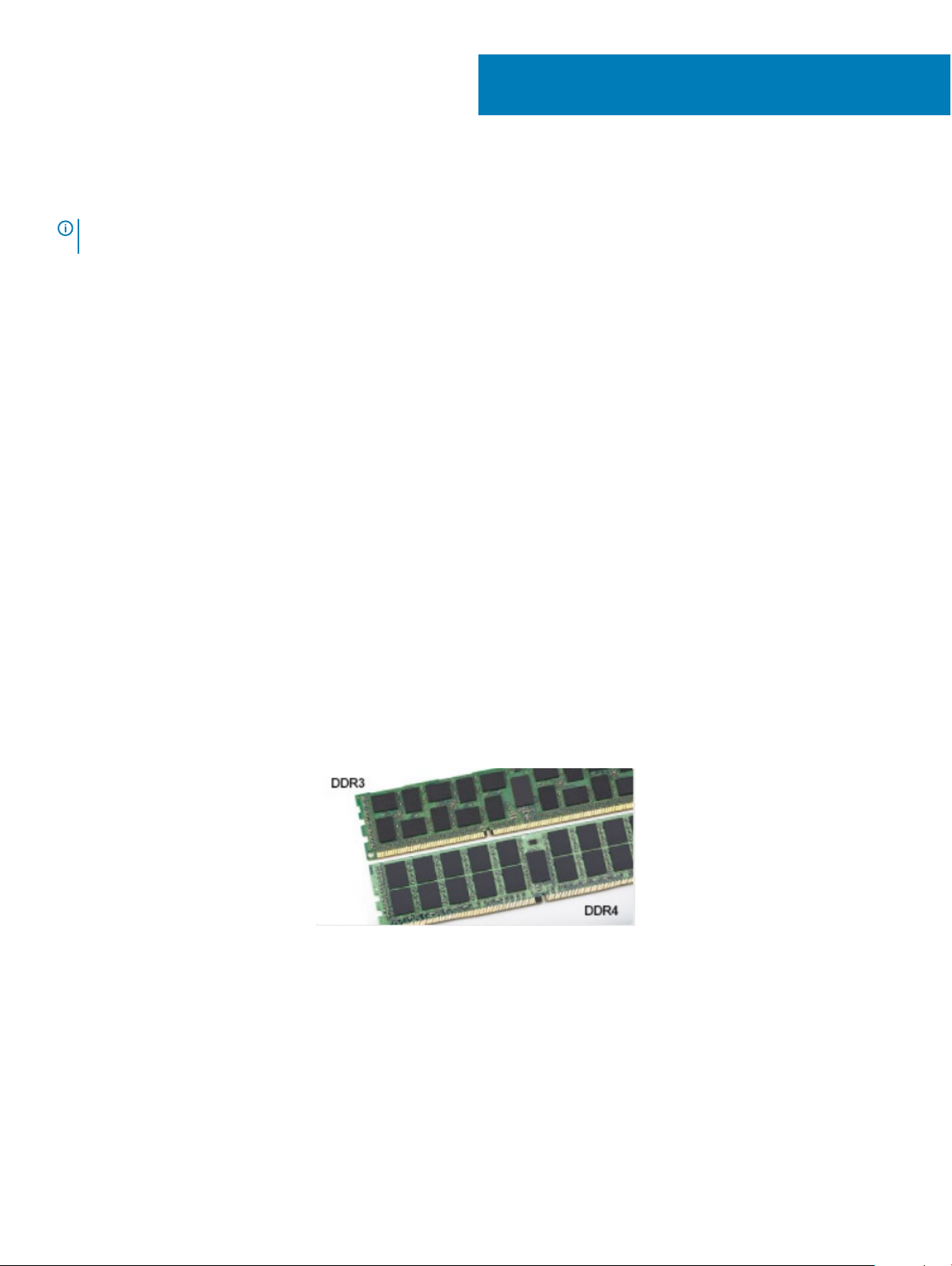
DDR4 Details
There are subtle dierences between DDR3 and DDR4 memory modules, as listed below.
Key notch dierence
The key notch on a DDR4 module is in a dierent location from the key notch on a DDR3 module. Both notches are on the insertion edge
but the notch location on the DDR4 is slightly dierent, to prevent the module from being installed into an incompatible board or platform.
Figure 1. Notch dierence
Increased thickness
DDR4 modules are slightly thicker than DDR3, to accommodate more signal layers.
8 Technology and components
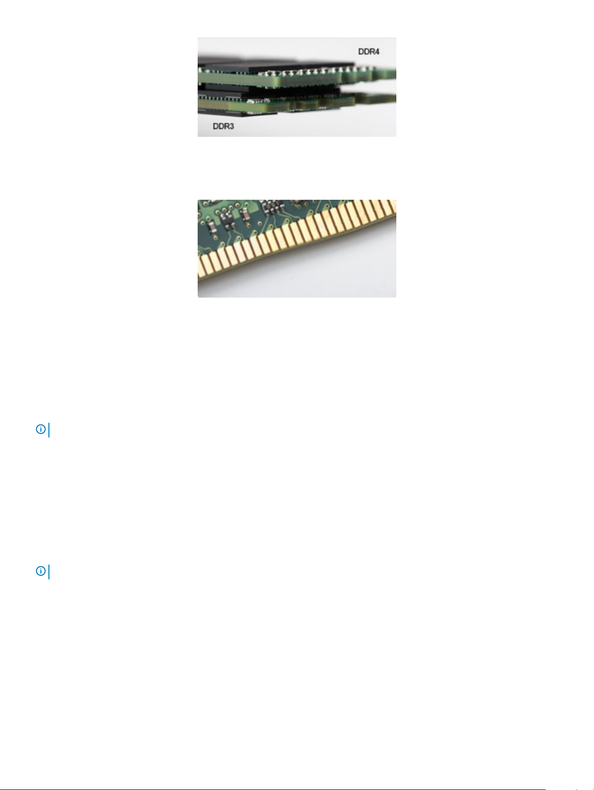
Figure 2. Thickness dierence
Curved edge
DDR4 modules feature a curved edge to help with insertion and alleviate stress on the PCB during memory installation.
Figure 3. Curved edge
Memory Errors
Memory errors on the system display the new ON-FLASH-FLASH or ON-FLASH-ON failure code. If all memory fails, the LCD does not
turn on. Troubleshoot for possible memory failure by trying known good memory modules in the memory connectors on the bottom of the
system or under the keyboard, as in some portable systems.
NOTE
: The DDR4 memory is imbedded in board and not a replaceable DIMM as shown and referred.
HDMI 1.4
This topic explains the HDMI 1.4 and its features along with the advantages.
HDMI (High-Denition Multimedia Interface) is an industry-supported, uncompressed, all-digital audio/video interface. HDMI provides an
interface between any compatible digital audio/video source, such as a DVD player, or A/V receiver and a compatible digital audio and/or
video monitor, such as a digital TV (DTV). The intended applications for HDMI TVs, and DVD players. The primary advantage is cable
reduction and content protection provisions. HDMI supports standard, enhanced, or high-denition video, plus multichannel digital audio on
a single cable.
NOTE
: The HDMI 1.4 will provide 5.1 channel audio support.
HDMI 1.4 Features
• HDMI Ethernet Channel - Adds high-speed networking to an HDMI link, allowing users to take full advantage of their IP-enabled
devices without a separate Ethernet cable
• Audio Return Channel - Allows an HDMI-connected TV with a built-in tuner to send audio data "upstream" to a surround audio system,
eliminating the need for a separate audio cable
• 3D - Denes input/output protocols for major 3D video formats, paving the way for true 3D gaming and 3D home theater applications
• Content Type - Real-time signaling of content types between display and source devices, enabling a TV to optimize picture settings
based on content type
Technology and components
9

• Additional Color Spaces - Adds support for additional color models used in digital photography and computer graphics
• 4K Support - Enables video resolutions far beyond 1080p, supporting next-generation displays that will rival the Digital Cinema systems
used in many commercial movie theaters
• HDMI Micro Connector - A new, smaller connector for phones and other portable devices, supporting video resolutions up to 1080p
• Automotive Connection System - New cables and connectors for automotive video systems, designed to meet the unique demands of
the motoring environment while delivering true HD quality
Advantages of HDMI
• Quality HDMI transfers uncompressed digital audio and video for the highest, crispest image quality.
• Low -cost HDMI provides the quality and functionality of a digital interface while also supporting uncompressed video formats in a
simple, cost-eective manner
• Audio HDMI supports multiple audio formats from standard stereo to multichannel surround sound
• HDMI combines video and multichannel audio into a single cable, eliminating the cost, complexity, and confusion of multiple cables
currently used in A/V systems
• HDMI supports communication between the video source (such as a DVD player) and the DTV, enabling new functionality
USB features
Universal Serial Bus, or USB, was introduced in 1996. It dramatically simplied the connection between host computers and peripheral
devices like mice, keyboards, external drivers, and printers.
Let's take a quick look on the USB evolution referencing to the table below.
Table 1. USB evolution
Type Data Transfer Rate Category Introduction Year
USB 2.0 480 Mbps High Speed 2000
USB 3.0/USB 3.1 Gen 1 5 Gbps Super Speed 2010
USB 3.1 Gen 2 10 Gbps Super Speed 2013
USB 3.0/USB 3.1 Gen 1 (SuperSpeed USB)
For years, the USB 2.0 has been rmly entrenched as the de facto interface standard in the PC world with about 6 billion devices sold, and
yet the need for more speed grows by ever faster computing hardware and ever greater bandwidth demands. The USB 3.0/USB 3.1 Gen 1
nally has the answer to the consumers' demands with a theoretically 10 times faster than its predecessor. In a nutshell, USB 3.1 Gen 1
features are as follows:
• Higher transfer rates (up to 5 Gbps)
• Increased maximum bus power and increased device current draw to better accommodate power-hungry devices
• New power management features
• Full-duplex data transfers and support for new transfer types
• Backward USB 2.0 compatibility
• New connectors and cable
The topics below cover some of the most commonly asked questions regarding USB 3.0/USB 3.1 Gen 1.
Technology and components
10
Speed
Currently, there are 3 speed modes dened by the latest USB 3.0/USB 3.1 Gen 1 specication. They are Super-Speed, Hi-Speed and FullSpeed. The new SuperSpeed mode has a transfer rate of 4.8Gbps. While the specication retains Hi-Speed, and Full-Speed USB mode,
commonly known as USB 2.0 and 1.1 respectively, the slower modes still operate at 480Mbps and 12Mbps respectively and are kept to
maintain backward compatibility.
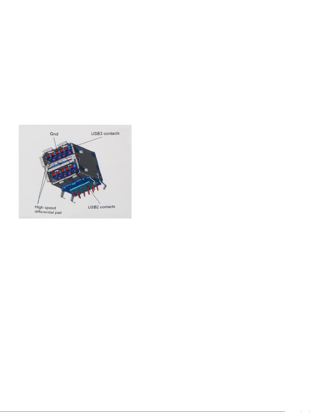
USB 3.0/USB 3.1 Gen 1 achieves the much higher performance by the technical changes below:
• An additional physical bus that is added in parallel with the existing USB 2.0 bus (refer to the picture below).
• USB 2.0 previously had four wires (power, ground, and a pair for dierential data); USB 3.0/USB 3.1 Gen 1 adds four more for two pairs
of dierential signals (receive and transmit) for a combined total of eight connections in the connectors and cabling.
• USB 3.0/USB 3.1 Gen 1 utilizes the bidirectional data interface, rather than USB 2.0's half-duplex arrangement. This gives a 10-fold
increase in theoretical bandwidth.
With today's ever increasing demands placed on data transfers with high-denition video content, terabyte storage devices, high megapixel
count digital cameras etc., USB 2.0 may not be fast enough. Furthermore, no USB 2.0 connection could ever come close to the 480Mbps
theoretical maximum throughput, making data transfer at around 320Mbps (40MB/s) — the actual real-world maximum. Similarly, USB
3.0/USB 3.1 Gen 1 connections will never achieve 4.8Gbps. We will likely see a real-world maximum rate of 400MB/s with overheads. At this
speed, USB 3.0/USB 3.1 Gen 1 is a 10x improvement over USB 2.0.
Applications
USB 3.0/USB 3.1 Gen 1 opens up the laneways and provides more headroom for devices to deliver a better overall experience. Where USB
video was barely tolerable previously (both from a maximum resolution, latency, and video compression perspective), it's easy to imagine
that with 5-10 times the bandwidth available, USB video solutions should work that much better. Single-link DVI requires almost 2Gbps
throughput. Where 480Mbps was limiting, 5Gbps is more than promising. With its promised 4.8Gbps speed, the standard will nd its way
into some products that previously weren't USB territory, like external RAID storage systems.
Listed below are some of the available SuperSpeed USB 3.0/USB 3.1 Gen 1 products:
• External Desktop USB 3.0/USB 3.1 Gen 1 Hard Drives
• Portable USB 3.0/USB 3.1 Gen 1 Hard Drives
• USB 3.0/USB 3.1 Gen 1 Drive Docks & Adapters
• USB 3.0/USB 3.1 Gen 1 Flash Drives & Readers
• USB 3.0/USB 3.1 Gen 1 Solid-state Drives
Technology and components
11

• USB 3.0/USB 3.1 Gen 1 RAIDs
• Optical Media Drives
• Multimedia Devices
• Networking
• USB 3.0/USB 3.1 Gen 1 Adapter Cards & Hubs
Compatibility
The good news is that USB 3.0/USB 3.1 Gen 1 has been carefully planned from the start to peacefully co-exist with USB 2.0. First of all,
while USB 3.0/USB 3.1 Gen 1 species new physical connections and thus new cables to take advantage of the higher speed capability of
the new protocol, the connector itself remains the same rectangular shape with the four USB 2.0 contacts in the exact same location as
before. Five new connections to carry receive and transmitted data independently are present on USB 3.0/USB 3.1 Gen 1 cables and only
come into contact when connected to a proper SuperSpeed USB connection.
Windows 10 will be bringing native support for USB 3.1 Gen 1 controllers. This is in contrast to previous versions of Windows, which
continue to require separate drivers for USB 3.0/USB 3.1 Gen 1 controllers.
Intel Optane memory
Intel Optane memory functions only as a storage accelerator. It neither replaces nor adds to the memory (RAM) installed on your computer.
NOTE
: Intel Optane memory is supported on computers that meet the following requirements:
• 7th Generation or higher Intel Core i3/i5/i7 processor
• Windows 10 64-bit version 1607 or higher
• Intel Rapid Storage Technology driver version 15.9.1.1018 or higher
Table 2. Intel Optane memory specications
Feature Specications
Interface PCIe 3x2 NVMe 1.1
Connector M.2 card slot (2230/2280)
Congurations supported
Capacity 16 GB
• 7th Generation or higher Intel Core i3/i5/i7 processor
• Windows 10 64-bit version 1607 or higher
• Intel Rapid Storage Technology driver version 15.9.1.1018 or
higher
Enabling Intel Optane memory
1 On the taskbar, click the search box, and type "Intel Rapid Storage Technology".
2 Click Intel Rapid Storage Technology.
3 On the Status tab, click Enable to enable the Intel Optane memory.
4 On the warning screen, select a compatible fast drive, and then click Yes to continue enabling Intel Optane memory.
5 Click Intel Optane memory > Reboot to enable the Intel Optane memory.
: Applications may take up to three subsequent launches after enablement to see the full performance benets.
NOTE
12 Technology and components

Disabling Intel Optane memory
About this task
CAUTION: After disabling Intel Optane memory, do not uninstall the driver for Intel Rapid Storage Technology as it will result in a
blue screen error. The Intel Rapid Storage Technology user interface can be removed without uninstalling the driver.
NOTE: Disabling Intel Optane memory is required before removing the SATA storage device, accelerated by the Intel Optane
memory module, from the computer.
Steps
1 On the taskbar, click the search box, and then type "Intel Rapid Storage Technology".
2 Click Intel Rapid Storage Technology. The Intel Rapid Storage Technology window is displayed.
3 On the Intel Optane memory tab, click Disable to disable the Intel Optane memory.
4 Click Yes if you accept the warning.
The disabling progress is displayed.
5 Click Reboot to complete disabling Intel Optane memory and restart your computer.
Technology and components 13
Removing and installing components
Recommended tools
The procedures in this document require the following tools:
• Phillips #0 screwdriver
• Phillips #1 screwdriver
• Plastic scribe
NOTE: The #0 screw driver is for screws 0-1 and the #1 screw driver is for screws 2-4
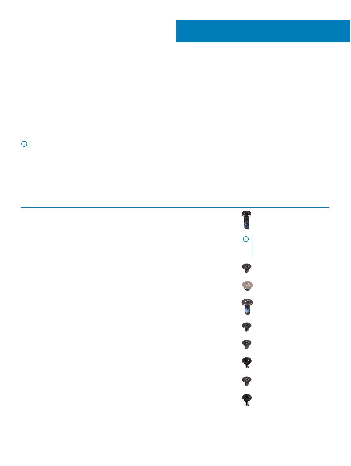
Screw list
The table provides the list of screws that are used for securing dierent components.
Table 3. Screw list
Component Screw type Quantity Screw image
3
Base cover M2.5x6 6
Battery M2x3 4
Display panel M2x2 4
System Fan M2x5 2
VGA daughterboard M2x3 2
Hard-drive assembly M2x3 4
Hard-drive bracket M3x3 4
Heat sink - discrete M2x3 3
NOTE: Screw color may vary
depending on the
conguration ordered.
Hinges M2.5x2.5 10
14 Removing and installing components

Component Screw type Quantity Screw image
I/O board M2x4 2
Optical-drive bracket M2x3 2
Optical-drive connector board M2x2 Big Head 1
Power-adapter port M2x2 1
Power-button board M2x3 1
Power button with ngerprint
reader (optional)
Solid-state drive M2x2 1
Solid-state drive M2x3 1
System board M2x4 1
Touchpad M2x2 6
Wireless-card bracket M2x3 1
M2x2 1
Micro Secure Digital Card
Removing the Micro Secure Digital Card
Prerequisite
1 Follow the procedure in Before working inside your computer
Steps
1 Push the Micro Secure Digital card to release it from the computer.
2 Slide the Micro Secure Digital card out of the computer.
Installing the Micro Secure Digital Card
1 Slide the Micro Secure Digital into the slot until it clicks into place.
2 Follow the procedures in After working inside your computer.
Removing and installing components
15
Optical drive assembly
Removing the optical drive assembly
Prerequisites
1 Follow the procedure in before working inside your computer
2 Remove the SD memory card
Steps
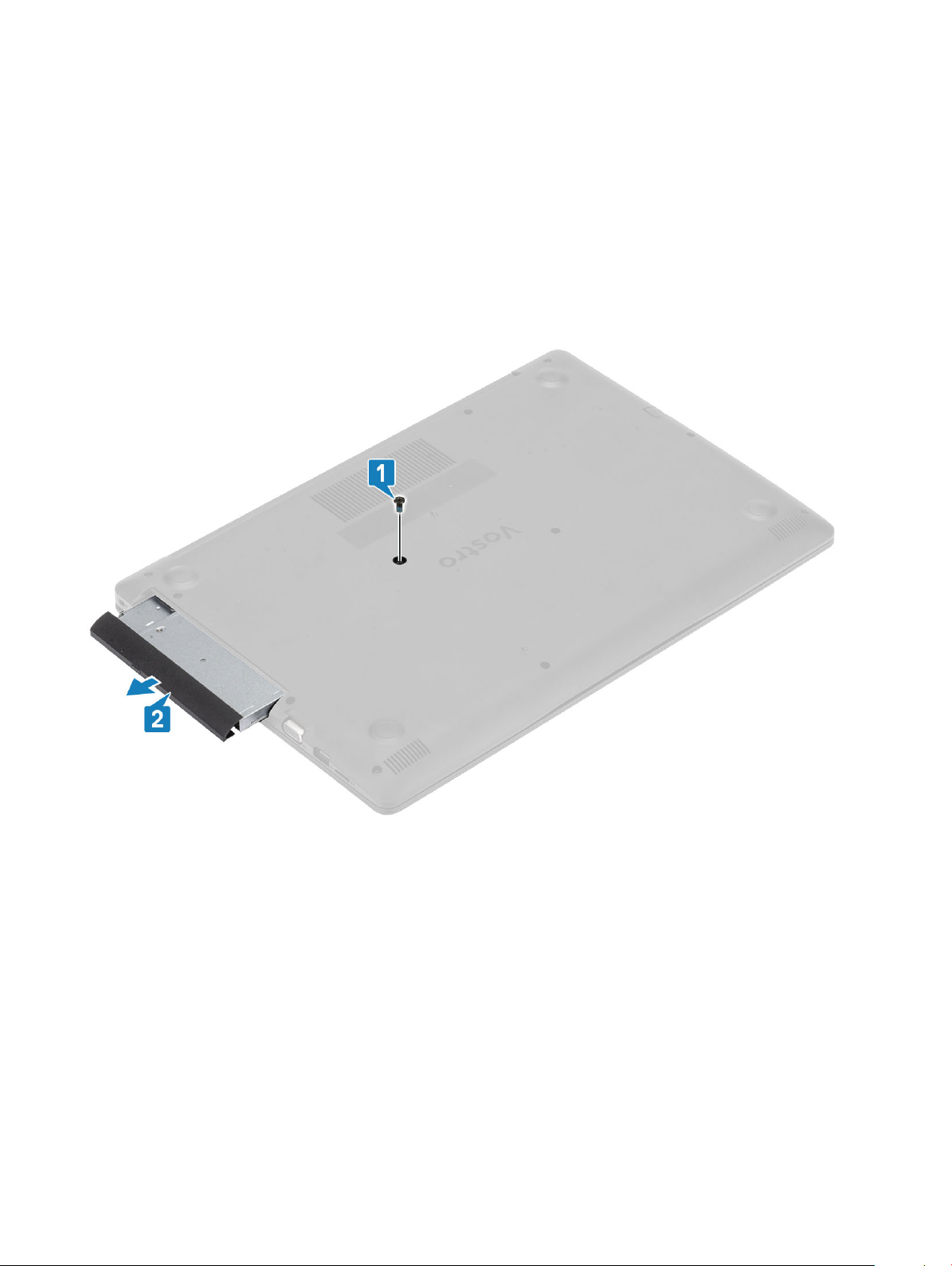
1 Remove the single (M2x5) screw that secures the optical drive to the system [1].
2 Slide the optical drive out of the computer [2].
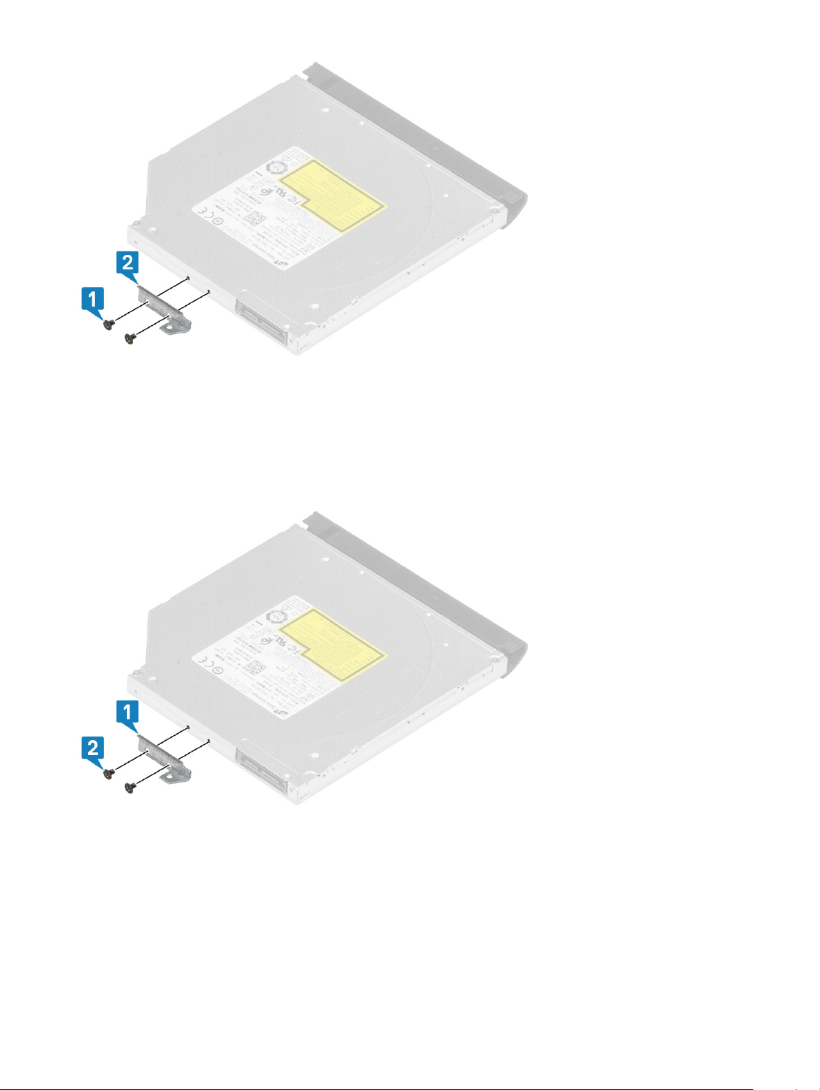
3 Remove the two (M2x3) screws that secure the optical drive bracket [1].
4 Remove the optical drive bracket from the optical drive [2].
16
Removing and installing components
Installing the optical drive assembly
Steps
1 Align the optical drive bracket to the screw holes on the optical drive [1].
2 Replace the two (M2x3) screws that secure the optical drive bracket [2].
3 Insert the optical drive into the slot until it clicks into place [1].
4 Replace the single (M2x5) screw that secures the optical drive to the system [2].
Removing and installing components
17

Next steps
1 Replace the SD memory card
2 Follow the procedure in after working inside your computer
Base cover
Removing the base cover
Prerequisites
1 Follow the procedure in before working inside your computer
2 Remove the SD memory card
3 Remove the optical drive assembly
Steps
1 Loosen the three captive screws [1].
2 Remove the single (M2x4) screw, two (M2x2) screws, and six (M2.5x7) screws that secure the base cover to the palmrest and
keyboard assembly [2, 3, 4].
Removing and installing components
18
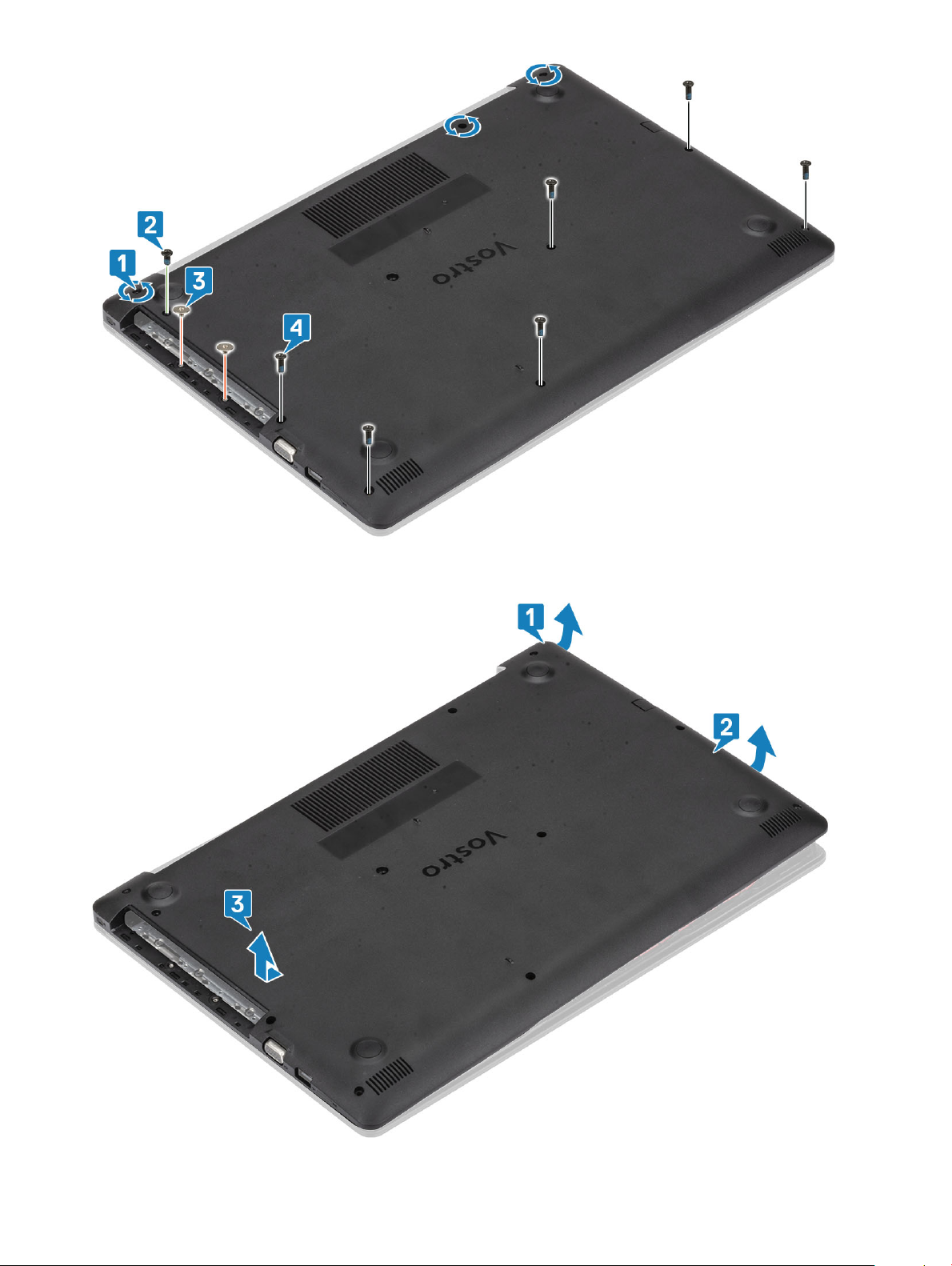
3 Pry the base cover from the top-right corner [1] and continue to open the right side of the base cover [2].
4 Lift the left side of the base cover and remove it o the system [3].
Removing and installing components
19
Installing the base cover
Steps
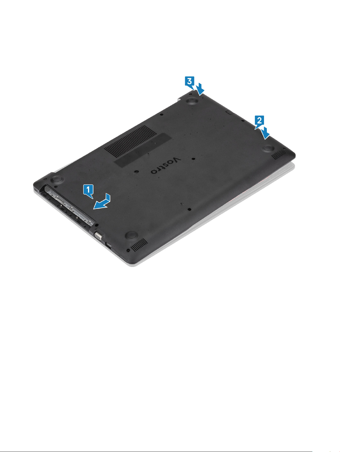
1 Place the base cover on the palmrest and keyboard assembly [1].
2 Press the right side of the base cover until it snaps into place [2, 3].
3 Tighten the three captive screws, and replace the single (M2x4) screw that secures the base cover to the palmrest and keyboard
assembly [1, 2].
4 Replace the two (M2x2) screws, and six (M2.5x7) screws that secure the base cover to the palmrest and keyboard assembly [3, 4].
20
Removing and installing components

Next steps
1 Replace the optical drive assembly
2 Replace the SD memory card
3 Follow the procedure in after working inside your computer
Battery
Lithium-ion battery precautions
CAUTION
• Exercise caution when handling Lithium-ion batteries.
• Discharge the battery as much as possible before removing it from the system. This can be done by disconnecting the AC adapter
• Do not crush, drop, mutilate, or penetrate the battery with foreign objects.
• Do not expose the battery to high temperatures, or disassemble battery packs and cells.
• Do not apply pressure to the surface of the battery.
• Do not bend the battery.
• Do not use tools of any kind to pry on or against the battery.
• If a battery gets stuck in a device as a result of swelling, do not try to free it as puncturing, bending, or crushing a Lithium-ion
• Always purchase genuine batteries from https://www.dell.com or authorized Dell partners and re-sellers.
:
from the system to allow the battery to drain.
battery can be dangerous. In such an instance, the entire system should be replaced. Contact https://www.dell.com/support for
assistance and further instructions.
Removing and installing components 21
Removing the battery
Prerequisites
1 Follow the procedure in before working inside your computer
2 Remove the SD memory card
3 Remove the optical drive assembly
4 Remove the base cover
Steps
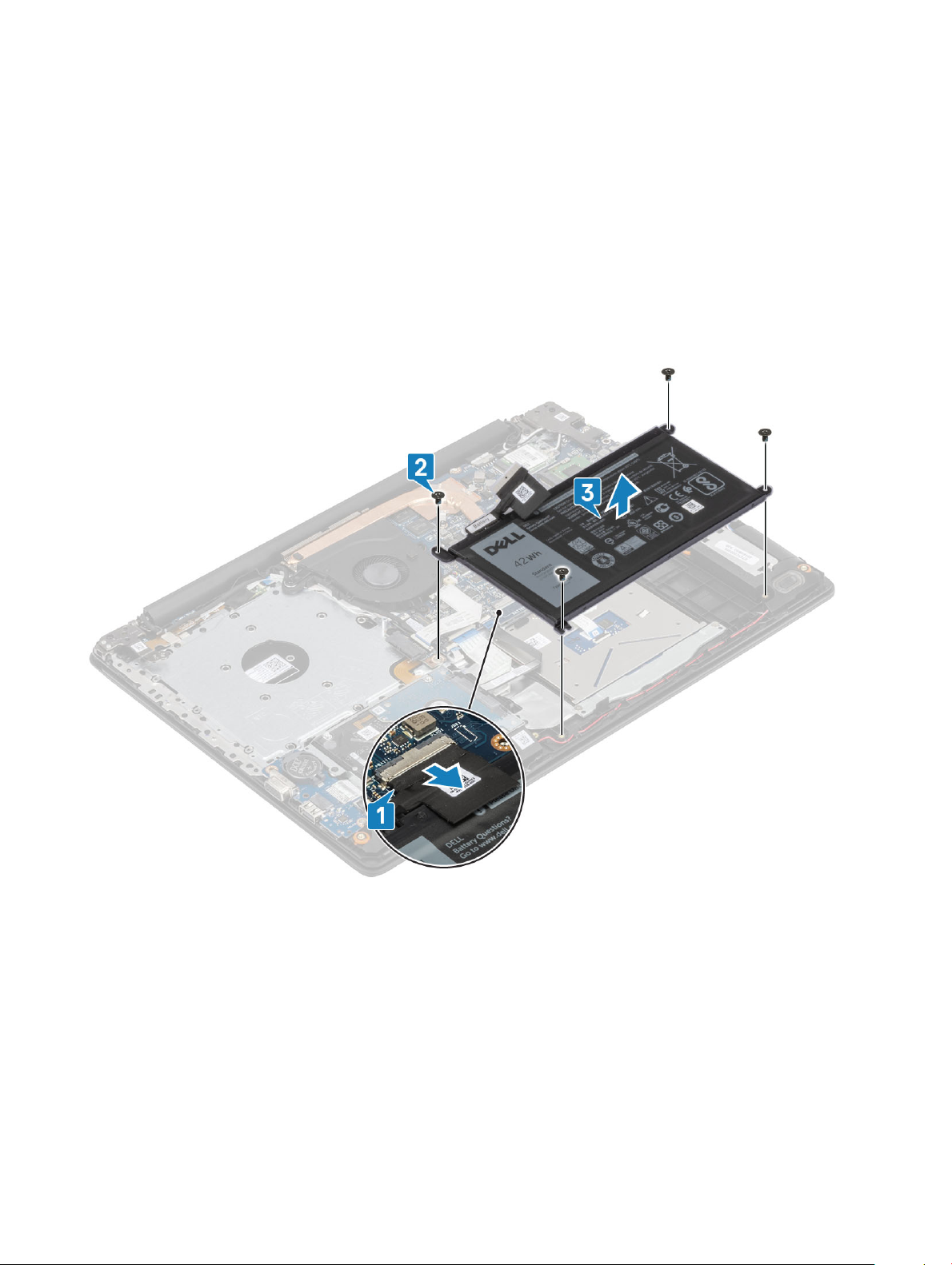
1 Disconnect the battery cable from the system board [1].
2 Remove the four (M2x3) screws that secure the battery to the palmrest and keyboard assembly [2].
3 Lift the battery o the palmrest and keyboard assembly [3].
Installing the battery
Steps
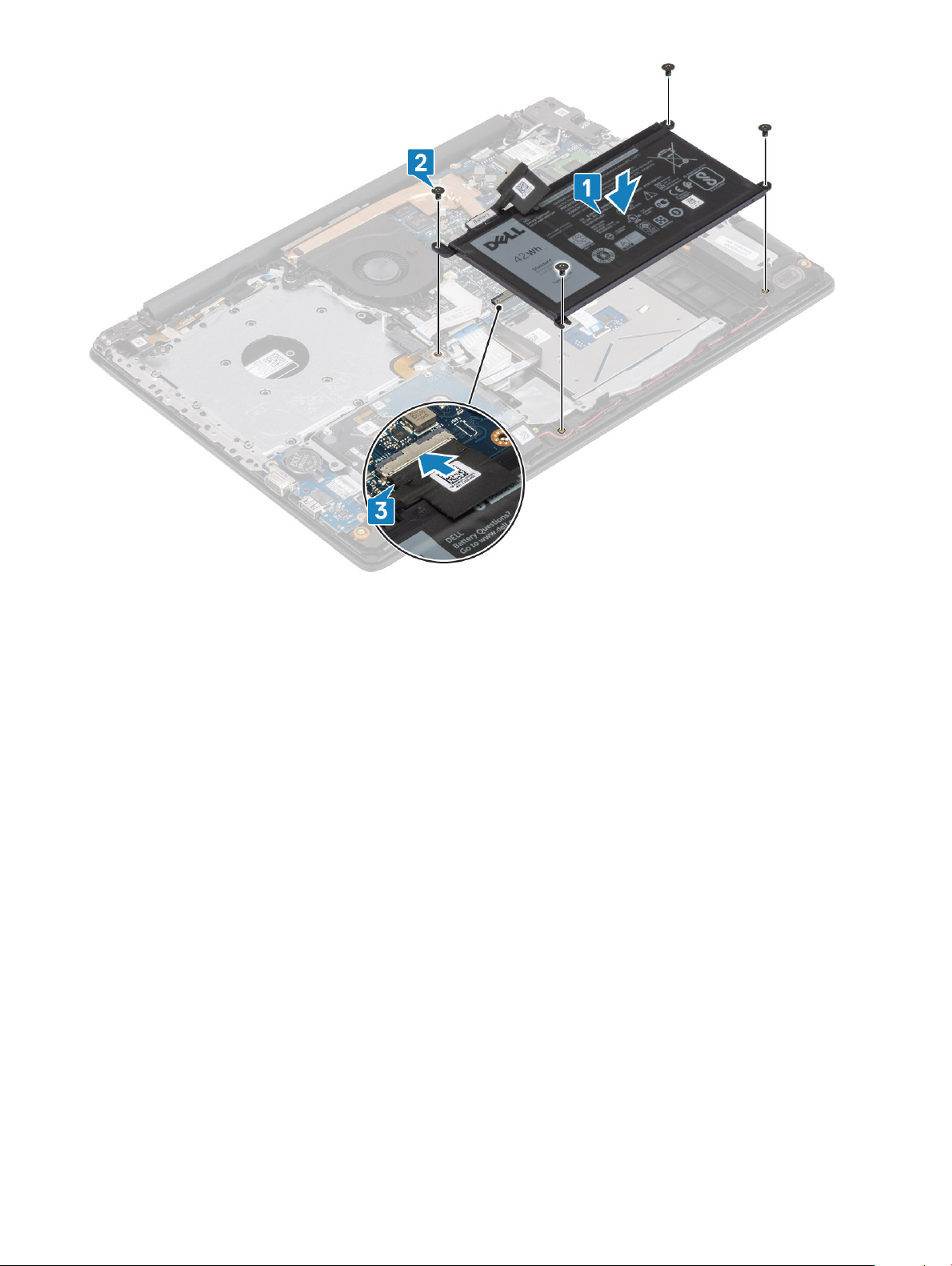
1 Align the screw holes on the battery with the screw holes on the palmrest and keyboard assembly [1].
2 Replace the four (M2x3) screws that secure the battery to the palmrest and keyboard assembly [2].
3 Connect the battery cable to the system board [3].
Removing and installing components
22
Next steps
1 Replace the base cover
2 Replace the optical drive assembly
3 Replace the SD memory card
4 Follow the procedure in after working inside your computer
Memory modules
Removing the memory module
Prerequisites
1 Follow the procedure in before working inside your computer
2 Remove the SD memory card
3 Remove the optical drive assembly
4 Remove the base cover
5 Remove the battery
Steps
1 Pry the clips securing the memory module until the memory module pops-up [1].
2 Remove the memory module from the memory module slot [2].
Removing and installing components
23
Installing the memory module
Steps
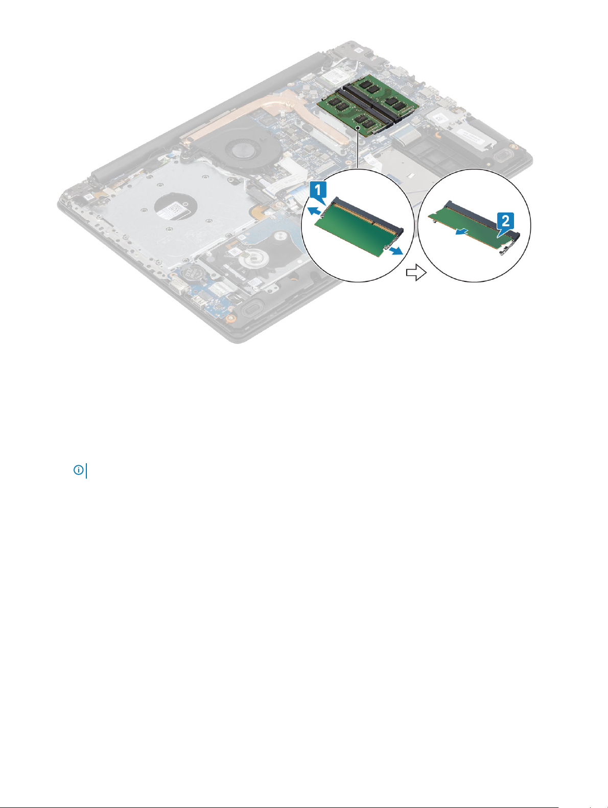
1 Align the notch on the memory module with the tab on the memory-module slot.
2 Slide the memory module rmly into the slot at an angle [1].
3 Press the memory module down until the clips secure it [2].
NOTE
: If you do not hear the click, remove the memory module and reinstall it.
24 Removing and installing components

Next steps
1 Replace the battery
2 Replace the base cover
3 Replace the optical drive assembly
4 Replace the SD memory card
5 Follow the procedure in after working inside your computer
WLAN card
Removing the WLAN card
Prerequisites
1 Follow the procedure in before working inside your computer
2 Remove the SD memory card
3 Remove the optical drive assembly
4 Remove the base cover
5 Remove the battery
Steps
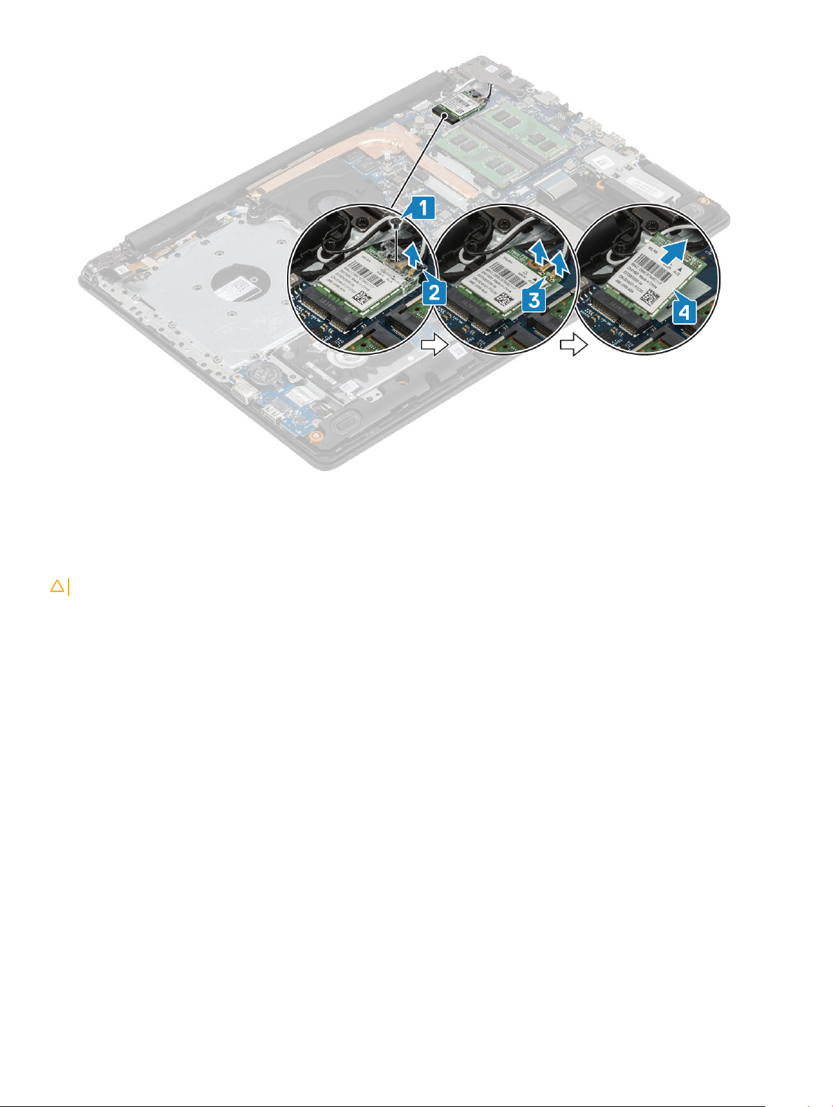
1 Remove the single (M2x3) screw that secures the WLAN card bracket to the system board [1].
2 Slide and remove the WLAN card bracket that secures the WLAN cables[2].
3 Disconnect the WLAN cables from the connectors on the WLAN card.
4 Lift the WLAN card away from the connector [4].
Removing and installing components
25
Installing the WLAN card
About this task
CAUTION
Steps
1 Insert the WLAN card into the connector on the system board [1].
2 Connect the WLAN cables to the connectors on the WLAN card [2].
3 Place the WLAN card bracket to secure the WLAN cables [3].
4 Replace the single (M2x3) screw to secure the WLAN bracket to the WLAN card [4].
: To avoid damage to the WLAN card, do not place any cables under it.
26
Removing and installing components

Next steps
1 Replace the battery
2 Replace the base cover
3 Replace the optical drive assembly
4 Replace the SD memory card
5 Follow the procedure in after working inside your computer
Solid-state drive/Intel Optane memory module
Removing the M.2 2230 Solid-state drive
Prerequisites
1 Follow the procedure in before working inside your computer
2 Remove the SD memory card
3 Remove the optical drive assembly
4 Remove the base cover
5 Remove the battery
Steps
1 Loosen the captive screw that secures the thermal plate to the palmrest and keyboard assembly [1].
2 Remove the single (M2x3) screw that secures the thermal plate to the palmrest and keyboard assembly [2].
3 Slide and remove the thermal plate from the solid-state drive slot [3].
Removing and installing components
27

4 Turn the thermal plate over.
5 Remove the single (M2x2) screw that secures the solid-state drive to the thermal plate [1].
6 Lift the solid-state drive o the thermal plate [2].
Installing the M.2 2230 Solid-state drive
Steps
1 Place the solid-state drive into the slot of the thermal plate [1].
2 Replace the single (M2x2) screw that secures the solid-state drive to the thermal plate [2].
Removing and installing components
28
 Loading...