

Page 1

ALIENWARE® AURORA
SERVICE MANUAL
01
/
01
Page 2

Notes, Cautions, and Warnings
NOTE: A NOTE indicates important information that helps you make better
use of your computer.
CAUTION: A CAUTION indicates either potential damage to hardware or
loss of data and tells you how to avoid the problem.
WARNING: A WARNING indicates a potential for property damage,
personal injury, or death.
e contents herein are subject to change without notice.
©2009-2010 Dell Inc. All rights reserved.
Reproduction of these materials in any manner whatsoever without the prior
written permission of Dell Inc. is strictly prohibited.
Trademarks used in this manual:
Corporation;
a registered trademark owned by Bluetooth SIG, Inc. and is used by Dell under
license;
trademarks or registered trademarks of Microsoft Corporation in the United
States and/or other countries;
Intel Corporation in the U.S. and other countries.
Other trademarks and trade names may be used in this manual to refer to either
the entities claiming the marks and names or their products. Dell Inc. disclaims
any proprietary interest in trademarks and trade names other than its own.
Model: D0IM Type: D0IM001; D0IM002 Rev. A01 FEBRUARY 2010
Dell
and the
Microsoft, Windows
Alienware
DELL
logo are trademarks of Dell Inc.;
, and the
Intel
and
is a registered trademark of Alienware
Windows
SpeedStep
start button logo are either
are registered trademarks of
Bluetooth
02
/
is
02
Page 3

CONTENTS
CONTENTS
CHAPTER 1: BEFORE YOU BEGIN.........................................6
Recommended Tools .............................................. 7
Turning O Your Computer ........................................ 7
Before Working Inside Your Computer . . . . . . . . . . . . . . . . . . . . . . . . . . . . . . 8
CHAPTER 2: LEFT SIDE-PANEL .......................................... 9
Removing the Left Side-Panel .....................................11
Replacing the Left Side-Panel......................................11
CHAPTER 3: TECHNICAL OVERVIEW .....................................12
Inside View of Your Computer .....................................13
System Board Components....................................... 14
Master I/O Board Components ....................................15
CHAPTER 4: SHROUDS .................................................16
Opening the PCI Shroud .......................................... 18
Closing the PCI Shroud ...........................................18
Removing the Drive-Bay Shroud .................................. 19
Replacing the Drive-Bay Shroud................................... 19
CHAPTER 5: DRIVE(S) .................................................20
Removing the Hard Drive(s) ......................................22
Replacing the Hard Drive(s).......................................24
Removing the Optical Drive(s) ....................................25
Replacing the Optical Drive(s).....................................26
Removing the Media Card Reader .................................27
Replacing the Media Card Reader .................................29
CHAPTER 6: PCI-EXPRESS CARD(S) ....................................30
Removing the PCI-Express Card(s) ................................32
Replacing the PCI-Express Card(s).................................33
CHAPTER 7: MEMORY MODULE(S)......................................35
Removing the Memory Module(s) .................................37
Replacing the Memory Module(s) .................................38
03
/
03
Page 4

CONTENTS
CHAPTER 8: FANS.....................................................40
Removing the Hard-Drive Fan Assembly...........................42
Replacing the Hard-Drive Fan Assembly ...........................43
Removing the PCI-Fan Assembly..................................44
Replacing the PCI-Fan Assembly ..................................45
CHAPTER 9: PROCESSOR LIQUID-COOLING ASSEMBLY...................46
Removing the Processor Liquid-Cooling Assembly .................48
Replacing the Processor Liquid-Cooling Assembly .................49
CHAPTER 10: PROCESSOR .............................................50
Removing the Processor..........................................52
Replacing the Processor ..........................................53
CHAPTER 11: POWER SUPPLY ..........................................55
Removing the Power Supply . . . . . . . . . . . . . . . . . . . . . . . . . . . . . . . . . . . . . . 57
Replacing the Power Supply ......................................59
CHAPTER 12: BATTERY ................................................60
Removing the Coin-Cell Battery ...................................62
Replacing the Coin-Cell Battery ...................................63
Removing the eater-Lighting Batteries .........................64
Replacing the eater-Lighting Batteries..........................65
CHAPTER 13: SYSTEM BOARD ..........................................66
Removing the System Board......................................68
Replacing the System Board ......................................69
CHAPTER 14: MASTER I/O BOARD ...................................... 70
Removing the Master I/O Board...................................72
Replacing the Master I/O Board ...................................73
CHAPTER 15: TOP LIGHTING-BOARD....................................74
Removing the Top Lighting-Board ................................76
Replacing the Top Lighting-Board.................................76
CHAPTER 16: RIGHT SIDE-PANEL(S) .....................................77
Removing the Right Side-Panel(s) ................................79
Replacing the Right Side-Panel(s).................................81
CHAPTER 17: ACTIVE-VENTING ASSEMBLY ..............................82
Removing the Active-Venting Assembly...........................84
Replacing the Active-Venting Assembly ...........................87
CHAPTER 18: FRONT BEZEL ............................................88
Removing the Front Bezel ........................................90
Replacing the Front Bezel ........................................92
04
/
04
Page 5

CHAPTER 19: BACK BEZEL .............................................93
Removing the Back Bezel.........................................95
Replacing the Back Bezel .........................................97
CHAPTER 20: BLUETOOTH ASSEMBLY ..................................98
Removing the Bluetooth Assembly...............................100
Replacing the Bluetooth Assembly............................... 101
CHAPTER 21: TOP I/O PANEL ..........................................102
Removing the Top I/O Panel .....................................104
Replacing the Top I/O Panel......................................105
CHAPTER 22: SYSTEM SETUP .........................................106
Conguring the BIOS ............................................107
Clearing Forgotten Passwords and CMOS Settings .................114
APPENDIX A: CONTACTING ALIENWARE ................................117
CONTENTS
05
/
05
Page 6

CHAPTER 1: BEFORE YOU BEGIN
CHAPTER 1: BEFORE YOU BEGIN
CHAPTER 1: BEFORE YOU BEGIN
is manual provides procedures for removing and installing the components
in your computer. Unless otherwise noted, each procedure assumes that the
following conditions exist:
You have performed the steps in “Turning O Your Computer” on page • 7 and
“Before Working Inside Your Computer” on page 8.
You have read the safety information that shipped with your computer.•
A component can be replaced or—if purchased separately—installed by •
performing the removal procedure in reverse order.
06
/
06
Page 7

CHAPTER 1: BEFORE YOU BEGIN
Recommended Tools
e procedures in this document may require the following tools:
Small at-blade screwdriver•
Phillips screwdriver•
BIOS executable update program available at • support.dell.com
Turning O Your Computer
CAUTION: To avoid losing data, save and close all open les and exit all
open programs before you turn o your computer.
Save and close all open les and exit all open programs.1.
Click 2. Start → Shut Down.
e computer turns o after the operating system shutdown process 3.
nishes.
Ensure that the computer is turned o. If your computer did not 4.
automatically turn o when you shut down the operating system, press and
hold the power button until the computer turns o.
07
/
07
Page 8

CHAPTER 1: BEFORE YOU BEGIN
Before Working Inside Your Computer
Use the following safety guidelines to help protect your computer from potential
damage and to help to ensure your own personal safety.
WARNING: Before you begin any of the procedures in this section, follow
the safety instructions that shipped with your computer. For additional
safety best practices information, see the Regulatory Compliance
Homepage at www.dell.com/regulatory_compliance.
CAUTION: Only a certied service technician should perform repairs on
your computer. Damage due to servicing that is not authorized by Dell is
not covered by your warranty.
CAUTION: When you disconnect a cable, pull on its connector or on its
pull-tab, not on the cable itself. Some cables have connectors with locking
tabs; if you are disconnecting this type of cable, press in on the locking
tabs before you disconnect the cable. As you pull connectors apart, keep
them evenly aligned to avoid bending any connector pins. Also, before
you connect a cable, ensure that both connectors are correctly oriented
and aligned.
CAUTION: To avoid damaging the computer, perform the following steps
before you begin working inside the computer.
Ensure that the work surface is at and clean.1.
Turn o your computer (see “Turning O Your Computer” on page 2. 7).
CAUTION: To disconnect a network cable, rst unplug the cable from
your computer and then unplug the cable from the network device.
Disconnect all telephone or network cables from the computer.3.
Disconnect your computer and all attached devices from their electrical 4.
outlets.
Disconnect all attached devices from your computer.5.
Press and eject any installed cards from the Media Card Reader.6.
Press and hold the power button to ground the system board.7.
CAUTION: Before touching anything inside your computer, ground
yourself by touching an unpainted metal surface, such as the metal at the
back of the computer. While you work, periodically touch an unpainted
metal surface to dissipate static electricity, which could harm internal
components.
NOTE: For better access to components within your computer, lay your
computer on its side.
08
/
08
Page 9

CHAPTER 2: SIDE PANEL
CHAPTER 2: LEFT SIDE-PANEL
CHAPTER 2: LEFT SIDE-PANEL
09
/
09
Page 10

Left Side-Panel
WARNING: Before working inside your computer, read the safety
information that shipped with your computer. For additional safety best
practices information, see the Regulatory Compliance Homepage at
www.dell.com/regulatory_compliance.
WARNING: To guard against likelihood of electric shock, laceration by
moving fan blades, or other unexpected injuries, always unplug your
computer from the electrical outlet before removing the side panel(s).
WARNING: Do not operate your computer with any cover(s) (including
computer covers, bezels, ller brackets, front-panel inserts, etc.)
removed.
CAUTION: Only a certied service technician should perform repairs on
your computer. Damage due to servicing that is not authorized by Dell™
is not covered by your warranty.
CHAPTER 2: LEFT SIDE-PANEL
010
/
010
Page 11
CHAPTER 2: LEFT SIDE-PANEL
1
3
2
4
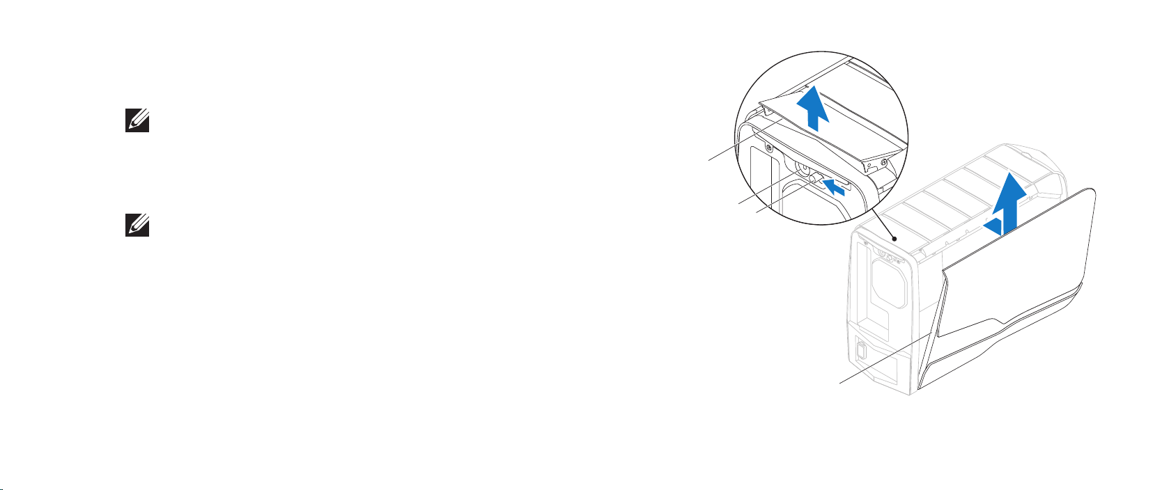
Removing the Left Side-Panel
Follow the instructions in “Before You Begin” on page 1. 6.
NOTE: Ensure that you remove the security cable from the security cable
slot (if applicable).
Slide the latch to unlock the release panel.2.
Lift the release panel to open the left-side panel.3.
Place the left side-panel in a secure location.4.
NOTE: eater lighting (available only in Alienware Aurora ALX) turns on
Replacing the Left Side-Panel
automatically when the left side-panel is removed.
Follow the instructions in “Before You Begin” on page 1. 6.
Align the tabs on the left side-panel with the slots on the side of the 2.
computer and push the panel in place.
Slide the latch to lock the release panel.3.
1 release panel 2 security cable slot
3 latch 4 left side-panel
011
/
011
Page 12

CHAPTER 3: TECHNICAL OVERVIEW
CHAPTER 3: TECHNICAL OVERVIEW
CHAPTER 3: TECHNICAL OVERVIEW
012
/
012
Page 13
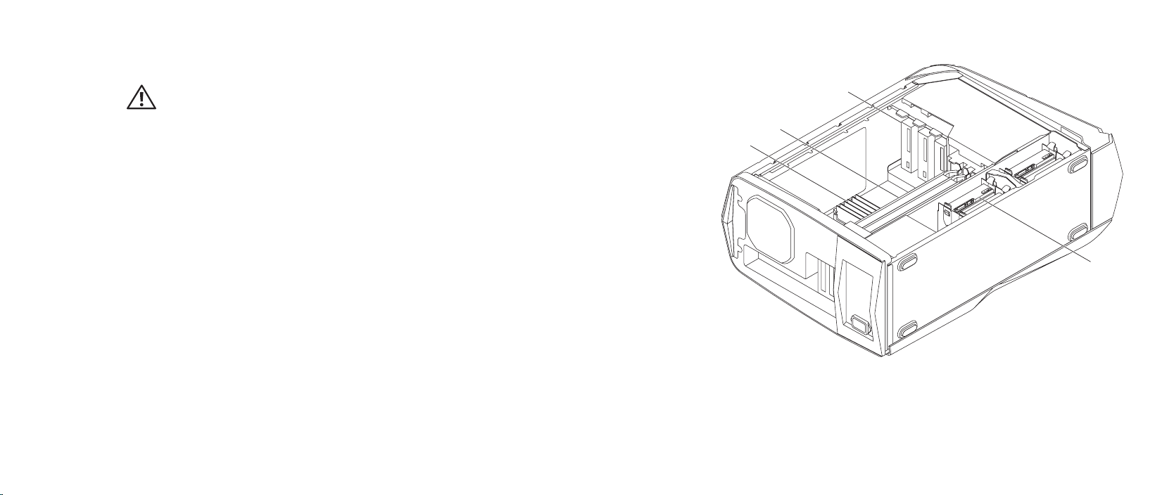
Inside View of Your Computer
WARNING: Before working inside your computer, read the safety
information that shipped with your computer. For additional safety best
practices information, see the Regulatory Compliance Homepage at
www.dell.com/regulatory_compliance.
CHAPTER 3: TECHNICAL OVERVIEW
3
2
1
4
1 memory module(s) 2 graphic cards (2)
3 optical drives (3) 4 hard drives (4)
013
/
013
Page 14
CHAPTER 3: TECHNICAL OVERVIEW
2021
2223
24
25
27
26
28
29
30
1
2 3
4
5
6 7 8
9
10
12
11
13
14
15
16
17
1819
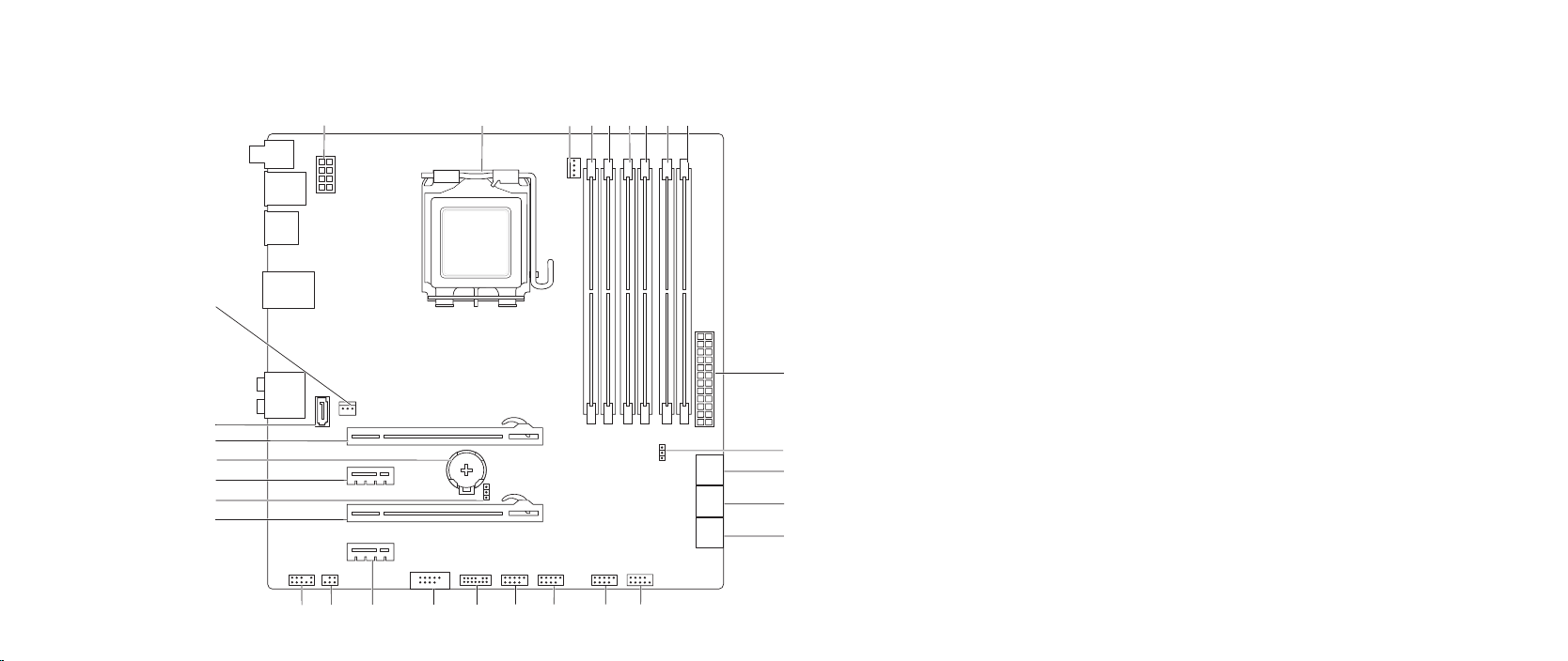
System Board Components
1 processor power connector (PWR2) 2 processor socket (CPU)
3 processor fan connector (MB_CPU_FAN) 4 memory-module connector (DIMM2)
5 memory-module connector (DIMM1) 6 memory-module connector (DIMM4)
7 memory-module connector (DIMM3)
(Aurora and Aurora ALX)
memory-module connector (DIMM2)
(Aurora-R2)
9 memory-module connector (DIMM5)
(Aurora and Aurora ALX only)
11 password jumper (PASSWORD) 12 serial ATA drive connectors (SATA1_2)
13 serial ATA drive connectors (SATA3_4) 14 serial ATA drive connectors (SATA5_6)
15 front panel connector (FRONT_PANEL) 16 USB connector (USB1)
17 USB connector (USB2) 18 USB connector (USB3)
19 Low pin count debug header (LPC1) 20 IEEE 1394 connector (1394)
21 PCI-Express x1 connector (SLOT4) 22 S/PDIF connector (SPDIF)
23 front audio connector (FRONT AUDIO) 24 PCI-Express x16 connector (SLOT3)
25 CMOS jumper (CLEAR_CMOS) 26 PCI-Express x1 connector (SLOT2)
27 battery socket (BAT1) 28 PCI-Express x16 connector (SLOT1)
29 eSATA connector (ESATA) 30 processor cooling assembly
(Aurora and Aurora ALX )
memory-module connector (DIMM3)
(Aurora-R2)
8 memory-module connector (DIMM6)
(Aurora and Aurora ALX only)
10 main power connector (PWR1)
(Aurora and Aurora ALX only)
014
connector (CHIPSET_FAN)
/
014
Page 15
CHAPTER 3: TECHNICAL OVERVIEW
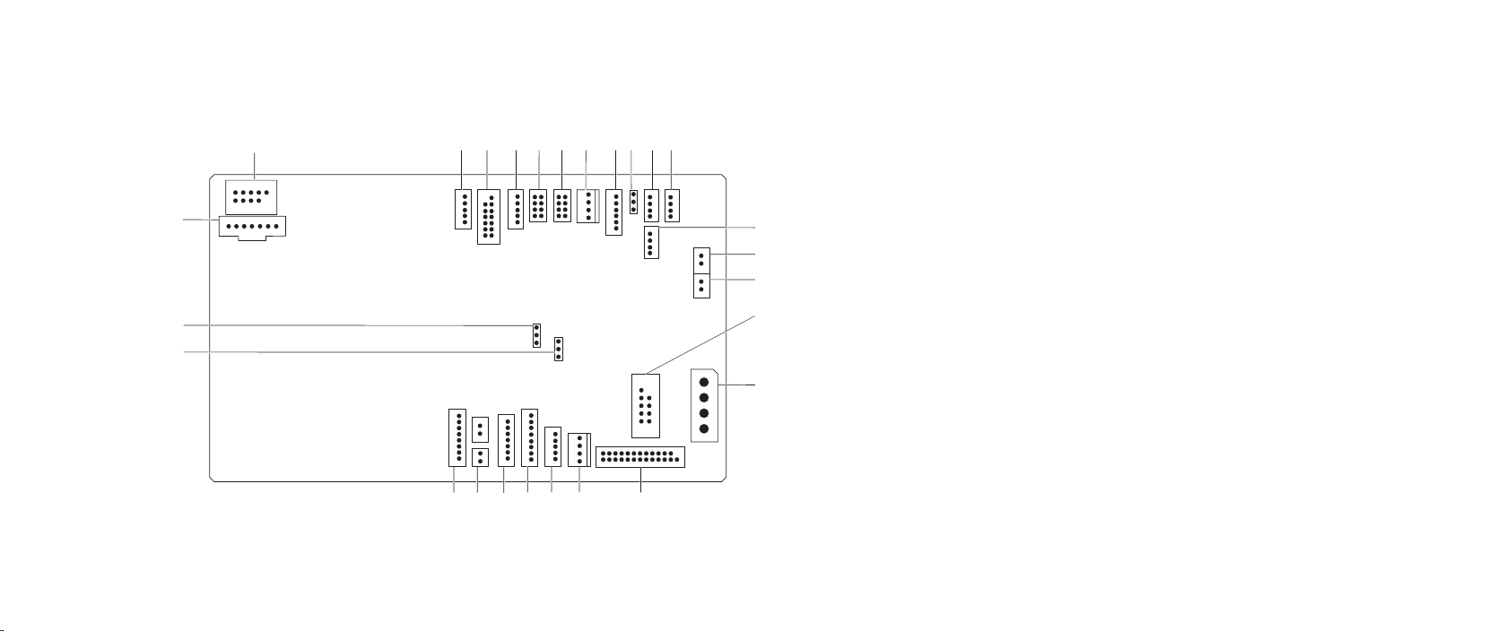
Master I/O Board Components
1
26
25
24
23
4
2
3
22
1 flexbay connector (FLEXBAY) 2 drive-bay shroud battery connector
(FRONT_BEZEL)
3 active-vent connector
5
6
8 9
7
10 11
(ACTIVE_VENT)
5 front-bezel right connector
(FRONT_RIGHT)
7 PCI-fan connector (FAN_PCI) 8 left side-panel contact board
12
13
14
15
16
2021
18
19
17
9 power-select connector (PWR_SEL) 10 Bluetooth® connector (BLUETOOTH)
11 power-LED board connector (BLINK) 12 wireless connector (WIRELESS)
13 hard-drive LED connector
(HDD_LED1)
15 USB connector (MB_USB) 16 main-power connector (PWR1)
17 system-board lighting (MB_MIO) 18 hard-drive fan connector (FAN_HDD)
19 right side-panel connector
(SIDE_R)
21 vent sensors (VENT_SW) 22 ODD sensors (ODD_SW)
23 vent-motor sensor connector
(VENT_MOTOR2)
25 front-default connector
(FACTORY_DEFAULT)
4 AlienHead connector (HEAD1)
6 front-bezel left connector
(FRONT_LEFT)
connector (SIDE_L)
14 hard-drive LED connector
(HDD_LED2)
20 vent-motor connector
(VENT_MOTOR1)
24 internal theater-lighting connector
(BAT2)
26 graphics-pump connector
(GFX_PUMP)
015
/
015
Page 16

CHAPTER 5: SHROUDS
CHAPTER 4: SHROUDS
CHAPTER 4: SHROUDS
016
/
016
Page 17

Shrouds
WARNING: Before working inside your computer, read the safety
information that shipped with your computer. For additional safety best
practices information, see the Regulatory Compliance Homepage at
www.dell.com/regulatory_compliance.
WARNING: Do not operate your computer with any cover(s) (including
computer covers, bezels, ller brackets, front-panel inserts, etc.)
removed.
WARNING: To guard against electrical shock, always unplug your
computer from the electrical outlet before removing the side panel(s).
CAUTION: Only a certied service technician should perform repairs on
your computer. Damage due to servicing that is not authorized by Dell™
is not covered by your warranty.
CHAPTER 4: SHROUDS
017
/
017
Page 18
Opening the PCI Shroud
1
2
Follow the instructions in “Before You Begin” on page 1. 6.
Remove the left side-panel (see “Removing the Left Side-Panel“ on page 2. 11).
Press the release button and rotate the PCI shroud away from the chassis.3.
Closing the PCI Shroud
Follow the instructions in “Before You Begin” on page 1. 6.
Lower the PCI shroud into the chassis until it clicks into place.2.
Replace the left side-panel (see “Replacing the Left Side-Panel“ on page 3. 11).
Connect your computer and devices to electrical outlets and then turn 4.
them on.
CHAPTER 4: SHROUDS
1 release button 2 PCI shroud
018
/
018
Page 19
2
1
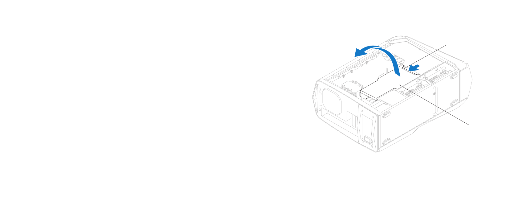
Removing the Drive-Bay Shroud
Follow the instructions in “Before You Begin” on page 1. 6.
Remove the left side-panel (see “Removing the Left Side-Panel“ on page 2. 11).
Open the PCI shroud (see “Opening the PCI Shroud” on page 3. 18).
Press the tabs and slide the drive-bay shroud towards the back of the 4.
chassis.
Disconnect the drive-bay shroud battery cable from the connector on the 5.
master I/O board.
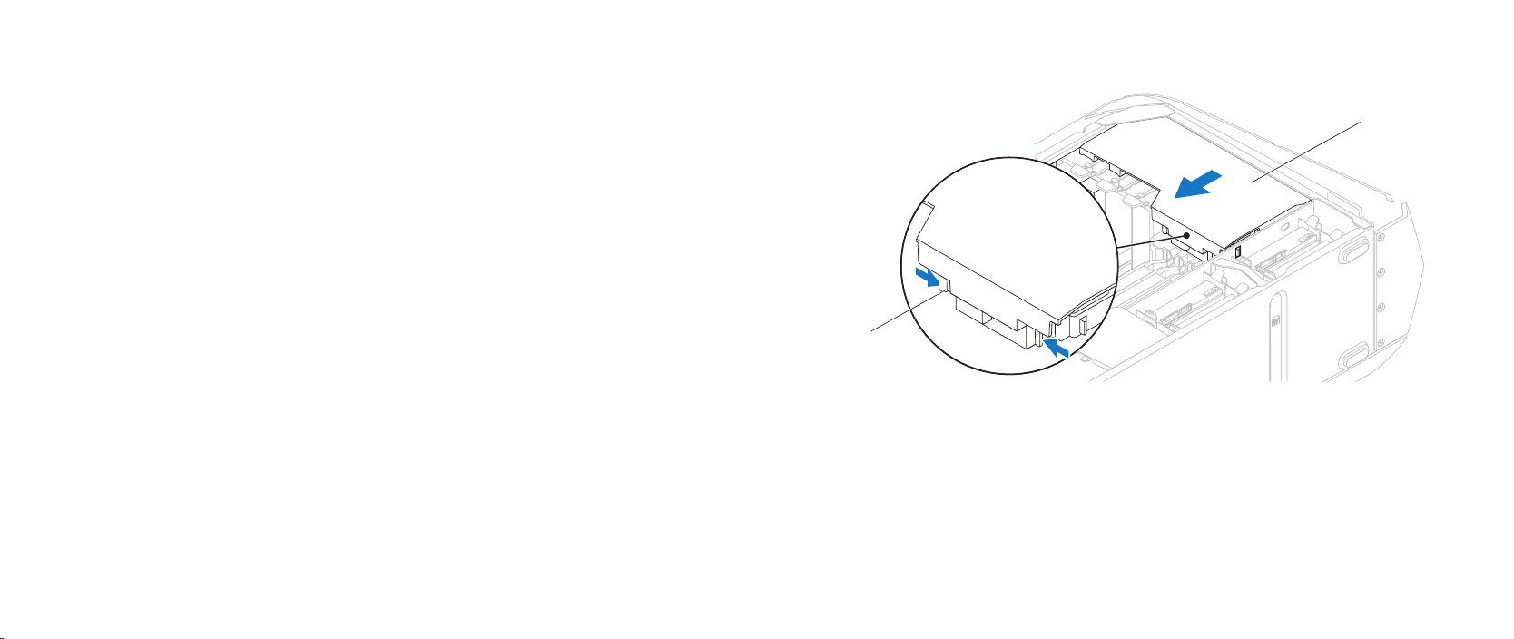
Replacing the Drive-Bay Shroud
CHAPTER 4: SHROUDS
Follow the instructions in “Before You Begin” on page 1. 6.
Connect the drive-bay shroud battery cable to the connector on the master 2.
I/O board.
Align the drive-bay shroud with the slots on the chassis.3.
Slide the drive-bay shroud toward the front of the chassis until it clicks into 4.
place.
Close the PCI shroud (see “Closing the PCI Shroud” on page 5. 18).
Replace the left side-panel (see “Replacing the Left Side-Panel“ on page 6. 11).
Connect your computer and devices to electrical outlets and then turn 7.
them on.
1 tabs (2) 2 drive-bay shroud
019
/
019
Page 20

CHAPTER 6: DRIVE(S)
CHAPTER 5: DRIVE(S)
CHAPTER 5: DRIVE(S)
020
/
020
Page 21
Drive(s)
WARNING: Before working inside your computer, read the safety
information that shipped with your computer. For additional safety best
practices information, see the Regulatory Compliance Homepage at
www.dell.com/regulatory_compliance.
WARNING: Do not operate your computer with any cover(s) (including
computer covers, bezels, ller brackets, front-panel inserts, etc.)
removed.
WARNING: To guard against electrical shock, always unplug your
computer from the electrical outlet before removing the side panel(s).
WARNING: If you remove the hard drive from the computer when the
drive is hot, do not touch the metal housing of the hard drive.
CAUTION: Only a certied service technician should perform repairs on
your computer. Damage due to servicing that is not authorized by Dell™
is not covered by your warranty.
CAUTION: To prevent data loss, turn o your computer (see “Turning
O Your Computer” on page 7) before removing the hard drive. Do not
remove the hard drive while the computer is on or in Sleep state.
CAUTION: Hard drives are extremely fragile. Exercise care when handling
the hard drive.
CHAPTER 5: DRIVE(S)
CAUTION: To avoid electrostatic discharge, ground yourself by using a
wrist grounding strap or by periodically touching an unpainted metal
surface (such as a connector on the back of the computer).
NOTE: Dell does not guarantee compatibility or provide support for hard
drives from sources other than Dell or Alienware.
NOTE: If you are installing a hard drive from a source other than Dell or
Alienware, you need to install an operating system, drivers, and utilities on
the new hard drive.
021
/
021
Page 22
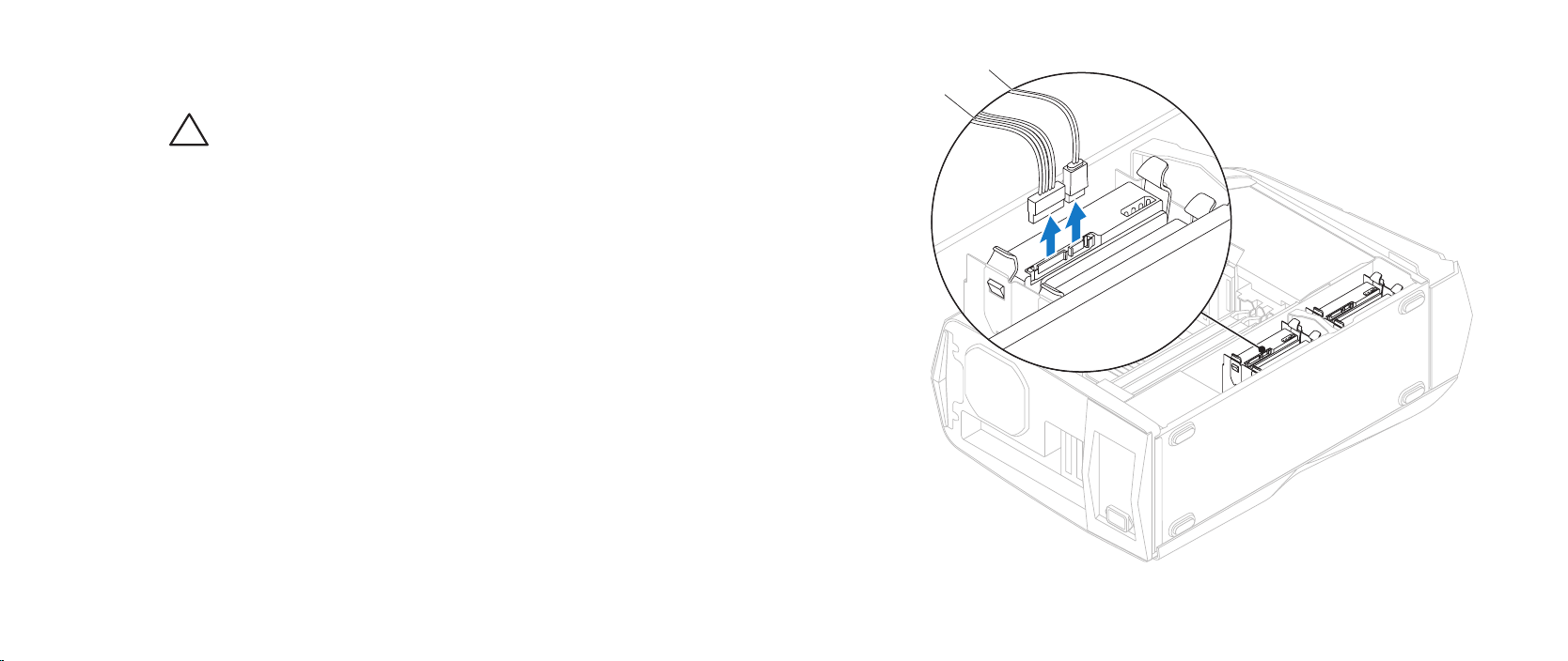
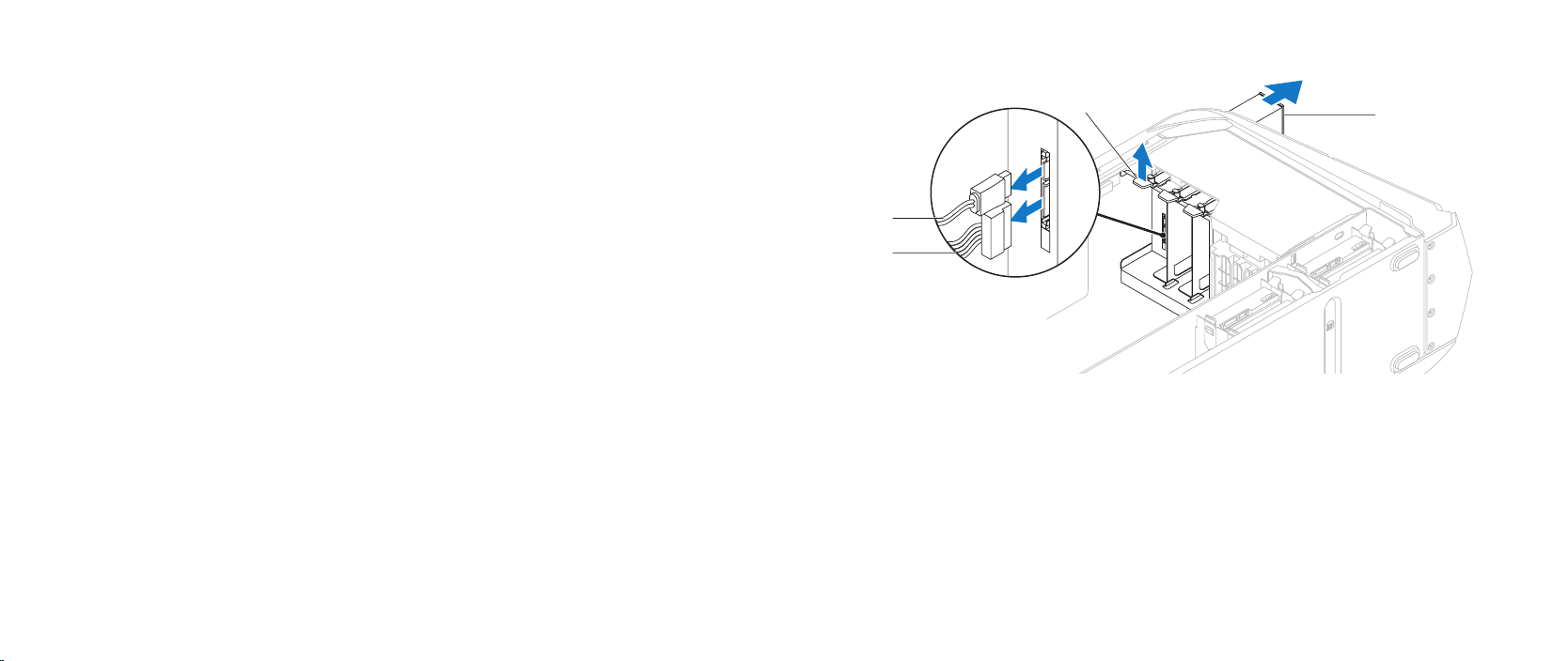
Removing the Hard Drive(s)
CAUTION: If you are replacing a hard drive that contains data you want
to keep, back up your les before you begin this procedure.
Follow the instructions in “Before You Begin” on page 1. 6.
Remove the left side-panel (see “Removing the Left Side-Panel“ on page 2. 11).
Disconnect the power and data cables from the hard-drive assembly 3.
(if applicable).
CHAPTER 5: DRIVE(S)
2
1
1 power cable 2 data cable
022
/
022
Page 23

CHAPTER 5: DRIVE(S)
1
2
2
1
Press the release tabs and slide the hard-drive assembly out of the hard- 4.
drive cage.
Remove the hard drive out of the hard-drive bracket by releasing the tabs 5.
and lifting the hard drive out of the bracket (if applicable).
1 hard drive 2 tabs (4)
1 hard-drive assembly 2 release tabs (2)
023
/
023
Page 24

Replacing the Hard Drive(s)
Follow the instructions in “Before You Begin” on page 1. 6.
See the documentation that shipped with your new hard drive and ensure 2.
that the jumper positioning is correct.
Snap the hard-drive bracket on to the new hard drive (if applicable).3.
Slide the hard-drive assembly into the hard-drive cage until the release tabs 4.
snap into place.
Connect the power and data cables to the hard-drive assembly 5.
(if applicable).
Replace the left side-panel (see “Replacing the Left Side-Panel“ on page 6. 11).
Connect your computer and devices to electrical outlets and then turn 7.
them on.
CHAPTER 5: DRIVE(S)
024
/
024
Page 25
2
3
4
1
Removing the Optical Drive(s)
Follow the instructions in “Before You Begin” on page 1. 6.
Press the AlienHead on the front of your computer to lower the drive panel.2.
Remove the left side-panel (see “Removing the Left Side-Panel“ on page 3. 11).
Open the PCI shroud (see “Opening the PCI Shroud” on page 4. 18).
Disconnect the power and data cables from the optical drive (if applicable).5.
Lift the securing tab and slide the optical drive out through the front of the 6.
computer.
CHAPTER 5: DRIVE(S)
1 power cable 2 data cable
3 securing tab 4 optical drive
025
/
025
Page 26

Replacing the Optical Drive(s)
Follow the instructions in “Before You Begin” on page 1. 6.
Remove the new optical drive from its packaging. Save the original 2.
packaging for storing or shipping the optical drive.
Remove the optical-drive bay ller (if applicable).3.
Lift the securing tab and slide the optical drive through the front of the 4.
computer until the securing tab snaps into place.
Connect the power and data cables to the optical drive (if applicable).5.
Close the PCI shroud (see “Closing the PCI Shroud” on page 6. 18).
Replace the left side-panel (see “Replacing the Left Side-Panel“ on page 7. 11).
Lift the drive panel towards the top of your computer.8.
Connect your computer and devices to electrical outlets and then turn 9.
them on.
CHAPTER 5: DRIVE(S)
026
/
026
Page 27
CHAPTER 5: DRIVE(S)
3
1
2
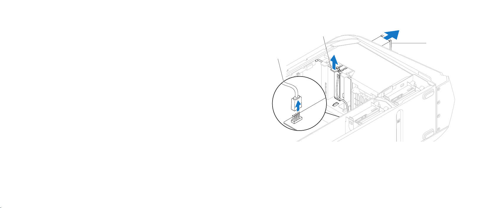
Removing the Media Card Reader
Follow the instructions in “Before You Begin” on page 1. 6.
Press the AlienHead on the front of your computer to lower the drive panel.2.
Remove the left side-panel (see “Removing the Left Side-Panel“ on page 3. 11).
Open the PCI shroud (see “Opening the PCI Shroud” on page 4. 18).
Disconnect the FlexBay USB cable from the connector on the master I/O 5.
board.
Lift the securing tab and slide the FlexBay dock out through the front of the 6.
computer.
1 FlexBay USB cable 2 securing tab
3 FlexBay dock
027
/
027
Page 28
1
3
2
CHAPTER 5: DRIVE(S)
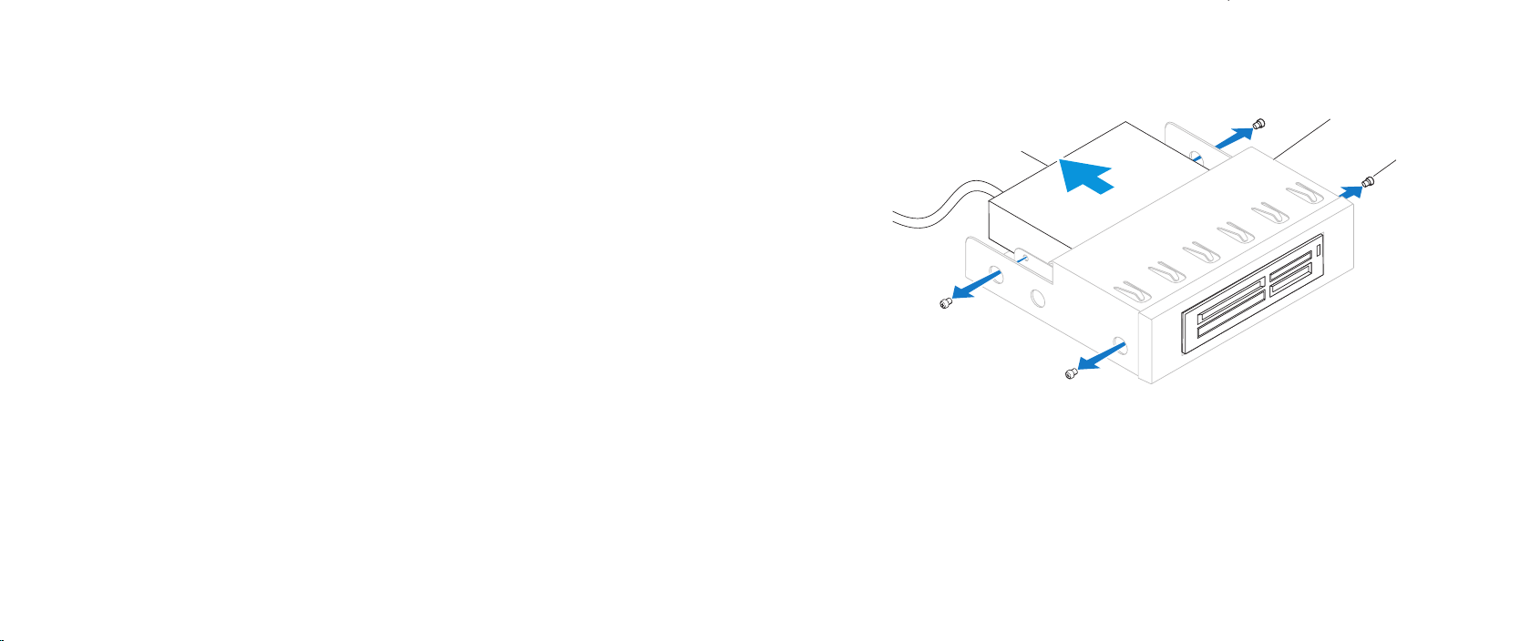
Remove the four screws that secure the Media Card Reader to the FlexBay 7.
dock.
Slide the Media Card Reader out of the FlexBay dock.8.
1 Media Card Reader 2 FlexBay dock
3 screws (4)
028
/
028
Page 29

Replacing the Media Card Reader
Follow the instructions in “Before You Begin” on page 1. 6.
Remove the new Media Card Reader from its packaging. Save the original 2.
packaging for storing or shipping the Media Card Reader.
Slide the Media Card Reader into the FlexBay dock.3.
Replace the four screws that secure the Media Card Reader to the FlexBay 4.
dock.
Lift the securing tab and slide the FlexBay dock through the front of the 5.
computer until the securing tab snaps into place.
Connect the FlexBay USB cable to the connector on the master I/O board.6.
Close the PCI shroud (see “Closing the PCI Shroud” on page 7. 18).
Replace the left side-panel (see “Replacing the Left Side-Panel“ on page 8. 11).
Lift the drive panel towards the top of your computer.9.
Connect your computer and devices to electrical outlets and then turn 10.
them on.
CHAPTER 5: DRIVE(S)
029
/
029
Page 30

CHAPTER 6: PCI EXPRESS CARD(S)
CHAPTER 6: PCI-EXPRESS CARD(S)
CHAPTER 6: PCI-EXPRESS CARD(S)
030
/
030
Page 31

PCI-Express Card(s)
WARNING: Before working inside your computer, read the safety
information that shipped with your computer. For additional safety best
practices information, see the Regulatory Compliance Homepage at
www.dell.com/regulatory_compliance.
WARNING: Do not operate your computer with any cover(s) (including
computer covers, bezels, ller brackets, front-panel inserts, etc.)
removed.
WARNING: To guard against electrical shock, always unplug your
computer from the electrical outlet before removing the side panel(s).
CAUTION: Only a certied service technician should perform repairs on
your computer. Damage due to servicing that is not authorized by Dell™
is not covered by your warranty.
CHAPTER 6: PCI-EXPRESS CARD(S)
031
/
031
Page 32

4
3
2
1
Removing the PCI-Express Card(s)
Follow the instructions in “Before You Begin” on page 1. 6.
Remove the left side-panel (see “Removing the Left Side-Panel“ on page 2. 11).
Open the PCI shroud (see “Opening the PCI Shroud” on page 3. 18).
Locate the PCI-Express card on the system board (see “System Board 4.
Components“ on page 14).
Disconnect any cables connected to the card (if applicable). 5.
Remove the screw that secures the card to the chassis.6.
Remove the card.7.
For a PCI-Express x1 card, grasp the card by its top corners, and ease it •
out the card connector.
For a PCI-Express x16 card, press the securing tab on the card •
connector as you grasp the card by its top corners, and then ease the
card out of the card connector.
CHAPTER 6: PCI-EXPRESS CARD(S)
NOTE: If you are not replacing a card, install a ller bracket in the empty
card-slot opening.
1 screw 2 card connector
3 securing tab 4 card
032
/
032
Page 33

CHAPTER 6: PCI-EXPRESS CARD(S)
1
2
Replacing the PCI-Express Card(s)
Follow the instructions in “Before You Begin” on page 1. 6.
Remove the ller bracket to create a card-slot opening (if applicable).2.
1 ller bracket 2 screw
033
/
033
Page 34

1
2
CAUTION: To prevent damage to the PCI-Express card ensure that the
memory module securing clips are in the closed position.
Align the card with the card connector on the system board. 3.
Place the card in the connector and press down rmly. Ensure that the card 4.
is rmly seated in the slot. If you are installing the PCI-Express x16 card,
push the securing tab and insert the card in the connector.
Connect any cables that should be attached to the card (if applicable). 5.
For information about the card’s cable connections, see the documentation
that shipped with the card.
Replace the screw that secures the card to the chassis.6.
Close the PCI shroud (see “Closing the PCI Shroud” on page 7. 18).
Replace the left side-panel (see “Replacing the Left Side-Panel“ on page 8. 11).
Connect your computer and devices to electrical outlets and then turn 9.
them on.
CHAPTER 6: PCI-EXPRESS CARD(S)
1 securing tab 2 card connector
034
/
034
Page 35

CHAPTER 7: MEMORY MODULE(S)
CHAPTER 4: MEMORY MODULE(S)
CHAPTER 7: MEMORY MODULE(S)
You can increase your computer memory by installing memory modules
on the system board. See the specications in your
support.dell.com/manuals for information on the type of memory supported
by your computer. Install only memory modules that are supported by your
computer.
NOTE: Memory modules purchased from Dell or Alienware are covered
under your computer warranty.
Desktop Manual
035
at
/
035
Page 36

Memory Module(s)
WARNING: Before working inside your computer, read the safety
information that shipped with your computer. For additional safety best
practices information, see the Regulatory Compliance Homepage at
www.dell.com/regulatory_compliance.
WARNING: Do not operate your computer with any cover(s) (including
computer covers, bezels, ller brackets, front-panel inserts, etc.)
removed.
WARNING: To guard against electrical shock, always unplug your
computer from the electrical outlet before removing the side panel(s).
CAUTION: Only a certied service technician should perform repairs on
your computer. Damage due to servicing that is not authorized by Dell™
is not covered by your warranty.
CHAPTER 7: MEMORY MODULE(S)
036
/
036
Page 37

Removing the Memory Module(s)
1
2
Follow the instructions in “Before You Begin” on page 1. 6.
Remove the left side-panel (see “Removing the Left Side-Panel“ on page 2. 11).
Locate the memory-module connectors on the system board (see “System 3.
Board Components“ on page 14).
WARNING: e memory module(s) may become very hot during normal
operation. Allow the memory module(s) to cool before touching them.
NOTE: For better access to the memory module(s), remove the graphics
card if the card is full length.
To remove the graphics card, see “Removing the PCI-Express Card(s)” on 4.
page 32.
Spread apart the securing clips at both ends of the memory-module 5.
connector.
Lift the memory module o the memory-module connector. If the memory 6.
module is difcult to remove, gently ease the memory module back and
forth to remove it from the memory-module connector.
CHAPTER 7: MEMORY MODULE(S)
1 memory-module connector 2 securing clips (2)
037
/
037
Page 38

Replacing the Memory Module(s)
Follow the instructions in “Before You Begin” on page 1. 6.
Recommended memory conguration:
Aurora/Aurora ALX
CHAPTER 7: MEMORY MODULE(S)
Aurora-R2
Type Slots
1066 MHz and I333 MHz DDR3 Slots 1, 3, and 5 or slots 1 — 6
1600 MHz XMP Slots 1, 3, and 5
Type Slots
1066 MHz and I333 MHz DDR3 Slots 1 and 2 or slots 1 — 4
038
/
038
Page 39

2
3
4
6
5
1
CHAPTER 7: MEMORY MODULE(S)
Align the notch on the bottom of the memory module with the tab on the 2.
memory-module connector.
Insert the memory module into the memory-module connector until the 3.
memory module snaps into position.
If you insert the memory module correctly, the securing clips snap into the
cutouts at each end of the memory module.
NOTE If the memory module is not installed properly, the computer may
not boot.
To replace the graphics card, see “Replacing the PCI-Express Card(s)” on 4.
page 33.
Replace the left side-panel (see “Replacing the Left Side-Panel“ on page 5. 11).
Connect your computer and devices to electrical outlets and then turn 6.
them on.
As the computer boots, it detects the additional memory and automatically
updates the system conguration information.
To conrm the amount of memory installed in the computer:
1 cutouts 2 memory-module connector
Click Start → Control Panel→ System and Security→ System.
3 tab 4 notch
5 securing clips (2) 6 memory module
CAUTION: To avoid damage to the memory module, press the memory
module straight down into the memory-module connector while you
apply equal force to each end of the memory module.
039
/
039
Page 40

CHAPTER 8: FANS
CHAPTER 8: FANS
CHAPTER 8: FANS
040
/
040
Page 41

Fans
CHAPTER 8: FANS
WARNING: Before working inside your computer, read the safety
information that shipped with your computer. For additional safety best
practices information, see the Regulatory Compliance Homepage at
www.dell.com/regulatory_compliance.
WARNING: To guard against electrical shock, always unplug your
computer from the electrical outlet before removing the side panel(s).
WARNING: Do not operate your computer with any cover(s) (including
computer covers, bezels, ller brackets, front-panel inserts, etc.)
removed.
CAUTION: Only a certied service technician should perform repairs on
your computer. Damage due to servicing that is not authorized by Dell™
is not covered by your warranty.
041
/
041
Page 42

1
2
Removing the Hard-Drive Fan Assembly
Follow the instructions in “Before You Begin” on page 1. 6.
Remove the left side-panel (see “Removing the Left Side-Panel“ on page 2. 11).
Open the PCI shroud (see “Opening the PCI Shroud” on page 3. 18).
Remove the drive-bay shroud (see “Removing the Drive-Bay Shroud” on 4.
page 19).
Disconnect the hard-drive fan assembly cable from the connector on the 5.
master I/O board. Make note of the cable routing before disconnecting the
cable.
Lift the hard-drive fan assembly out of the chassis.6.
CHAPTER 8: FANS
1 hard-drive fan assembly cable 2 hard-drive fan assembly
042
/
042
Page 43

Replacing the Hard-Drive Fan Assembly
Follow the instructions in “Before You Begin” on page 1. 6.
Push the hard-drive fan assembly into the hard-drive fan assembly bay.2.
Route the cable through the slot in the hard-drive bay.3.
Connect the hard-drive fan assembly cable to the connector on the master 4.
I/O board.
Replace the drive-bay shroud (see “Replacing the Drive-Bay Shroud” on 5.
page 19).
Close the PCI shroud (see “Closing the PCI Shroud” on page 6. 18).
Replace the left side-panel (see “Replacing the Left Side-Panel“ on page 7. 11).
Connect your computer and devices to electrical outlets and then turn 8.
them on.
CHAPTER 8: FANS
043
/
043
Page 44

1
2
3
Removing the PCI-Fan Assembly
Follow the instructions in “Before You Begin” on page 1. 6.
Remove the left side-panel (see “Removing the Left Side-Panel“ on page 2. 11).
Open the PCI shroud (see “Opening the PCI Shroud” on page 3. 18).
Remove the drive-bay shroud (see “Removing the Drive-Bay Shroud” on 4.
page 19).
Remove full-length PCI-Express cards, if any (see “Removing the PCI-Express 5.
Card(s)” on page 32).
Disconnect the PCI-fan assembly cable from the connector on the master 6.
I/O board.
Press the tabs and lift the PCI-fan assembly out of the chassis.7.
1 PCI-fan assembly cable 2 PCI-fan assembly
3 tabs (2)
CHAPTER 8: FANS
044
/
044
Page 45

Replacing the PCI-Fan Assembly
Follow the instructions in “Before You Begin” on page 1. 6.
Align the PCI-fan assembly with the metal bracket on the chassis.2.
Slide the PCI-fan assembly into the chassis.3.
Connect the PCI-fan assembly cable to the connector on the master 4.
I/O board.
Replace full-length PCI-Express cards, if any (see “Replacing the PCI-Express 5.
Card(s)” on page 33).
Replace the drive-bay shroud (see “Replacing the Drive-Bay Shroud” on 6.
page 19).
Close the PCI shroud (see “Closing the PCI Shroud” on page 7. 18).
Replace the left side-panel (see “Replacing the Left Side-Panel“ on page 8. 11).
Connect your computer and devices to electrical outlets and then turn 9.
them on.
CHAPTER 8: FANS
045
/
045
Page 46

CHAPTER 9: LIQUID COOLING ASSEMBLY
CHAPTER 9: PROCESSOR LIQUID-COOLING
ASSEMBLY
CHAPTER 9: PROCESSOR LIQUID-COOLING ASSEMBLY
046
/
046
Page 47

Processor Liquid-Cooling Assembly
WARNING: Before working inside your computer, read the safety
information that shipped with your computer. For additional safety best
practices information, see the Regulatory Compliance Homepage at
www.dell.com/regulatory_compliance.
WARNING: To guard against electrical shock, always unplug your
computer from the electrical outlet before removing the side panel(s).
WARNING: Do not operate your computer with any cover(s) (including
computer covers, bezels, ller brackets, front-panel inserts, etc.)
removed.
CAUTION: Only a certied service technician should perform repairs on
your computer. Damage due to servicing that is not authorized by Dell™
is not covered by your warranty.
CAUTION: To avoid electrostatic discharge, ground yourself by using a
wrist grounding strap or by periodically touching an unpainted metal
surface (such as a connector on the back of the computer).
CHAPTER 9: PROCESSOR LIQUID-COOLING ASSEMBLY
047
/
047
Page 48

Removing the Processor Liquid-Cooling Assembly
CHAPTER 9: PROCESSOR LIQUID-COOLING ASSEMBLY
Follow the instructions in “Before You Begin” on page 1. 6.
Remove the left side-panel (see “Removing the Left Side-Panel“ on page 2. 11).
WARNING: Despite having a plastic shield, the processor liquid-cooling
assembly may be very hot during normal operation. Ensure that it has
had sufcient time to cool before you touch it.
Disconnect the processor liquid-cooling assembly cable from the connectors 3.
(SYS FAN and CPU PUMP) on the top-lighting board.
Loosen the four captive screws that secure the processor liquid-cooling 4.
assembly to the system board.
Remove the four screws that secure the processor liquid-cooling assembly 5.
to the chassis rear wall.
Slide and lift the processor liquid-cooling assembly away from the chassis.6.
5
1 processor liquid-cooling assembly 2 top lighting-board
3 cables (2) 4 captive screws (4)
5 screws (4)
1
2
3
4
048
/
048
Page 49

Replacing the Processor Liquid-Cooling Assembly
Follow the instructions in “Before You Begin” on page 1. 6.
Align the screw holes on the processor liquid-cooling assembly with the 2.
screw holes on the chassis rear wall.
Replace the four screws that secure the processor liquid-cooling assembly 3.
to the chassis rear wall.
Tighten the four captive screws that secure the processor liquid-cooling 4.
assembly to the system board.
Connect the processor liquid-cooling assembly cables to the connectors 5.
(SYS FAN and CPU PUMP) on the top lighting-board.
Replace the left side-panel (see “Replacing the Left Side-Panel“ on page 6. 11).
Connect your computer and devices to electrical outlets and then turn 7.
them on.
CHAPTER 9: PROCESSOR LIQUID-COOLING ASSEMBLY
049
/
049
Page 50

CHAPTER 9: PROCESSOR
CHAPTER 10: PROCESSOR
CHAPTER 10: PROCESSOR
050
/
050
Page 51

Processor
WARNING: Before working inside your computer, read the safety
information that shipped with your computer. For additional safety best
practices information, see the Regulatory Compliance Homepage at
www.dell.com/regulatory_compliance.
WARNING: To guard against electrical shock, always unplug your
computer from the electrical outlet before removing the side panel(s).
CAUTION: Only a certied service technician should perform repairs on
your computer. Damage due to servicing that is not authorized by Dell™
is not covered by your warranty.
CAUTION: To avoid electrostatic discharge, ground yourself by using a
wrist grounding strap or by periodically touching an unpainted metal
surface (such as a connector on the back of the computer).
CHAPTER 10: PROCESSOR
051
/
051
Page 52

Removing the Processor
Follow the instructions in “Before You Begin” on page 1. 6.
Remove the left side-panel (see “Removing the Left Side-Panel“ on page 2. 11).
WARNING: Despite having a plastic shield, the processor liquid-cooling
assembly may be very hot during normal operation. Ensure that it has
had sufcient time to cool before you touch it.
Remove the processor liquid-cooling assembly (see “Removing the 3.
Processor Liquid-Cooling Assembly” on page 48).
Press and push the release lever down and out and release it from the tab 4.
that secures it.
CAUTION: When removing the processor, do not touch any of the pins
inside the socket or allow any objects to fall on the pins in the socket.
Open the processor cover and gently lift the processor to remove it from the 5.
socket.
Leave the release lever extended in the release position so that the socket is 6.
ready for the new processor.
CHAPTER 10: PROCESSOR
1
5
1 processor cover 2 processor
3 socket 4 release lever
5 tab
2
3
4
052
/
052
Page 53

2
4
6
3
1
7
5
Replacing the Processor
CAUTION: When replacing the processor, do not touch any of the pins inside
the socket or allow any objects to fall on the pins in the socket.
CAUTION: Ground yourself by touching an unpainted metal surface on
the back of the computer.
Follow the instructions in “Before You Begin” on page 1. 6.
Unpack the new processor. Ensure that you do not to touch the underside of 2.
the processor.
CAUTION: You must position the processor correctly in the socket to
avoid permanent damage to the processor and the computer when you
turn on the computer.
Extend the release lever on the processor socket if it is not fully extended.3.
CHAPTER 10: PROCESSOR
CAUTION: Socket pins are delicate. To avoid damage, ensure that the
processor is aligned properly with the socket, and do not use excessive
force when you replace the processor. Be careful not to touch or bend
the pins on the system board.
Align the pin-1 corners of the processor and socket. 4.
Set the processor lightly in the socket and ensure that the processor is 5.
positioned correctly.
1 tab 2 processor cover
3 processor 4 socket
5 center-cover latch 6 release lever
7 processor pin-1 indicator
053
/
053
Page 54

When the processor is fully seated in the socket, close the processor cover.6.
Ensure that the tab on the processor cover is positioned underneath the
center-cover latch on the socket.
Pivot the socket release lever back towards the socket, and snap it into place 7.
to secure the processor.
Clean the thermal grease from the bottom of the processor liquid-cooling 8.
assembly.
CAUTION: Ensure that you apply new thermal grease. New thermal
grease is critical for ensuring adequate thermal bonding, which is a
requirement for optimal processor operation.
Apply the new thermal grease to the top of the processor. 9.
Replace the processor liquid-cooling assembly (see “Replacing the Processor 10.
Liquid-Cooling Assembly” on page 49).
CAUTION: Ensure that the processor liquid-cooling assembly is correctly
seated and secured.
Replace the left side-panel (see “Replacing the Left Side-Panel“ on page 11. 11).
Connect your computer and devices to electrical outlets, and then turn 12.
them on.
CHAPTER 10: PROCESSOR
054
/
054
Page 55

CHAPTER 10: POWER SUPPLY
CHAPTER 11: POWER SUPPLY
CHAPTER 11: POWER SUPPLY
055
/
055
Page 56

Power Supply
WARNING: Before working inside your computer, read the safety
information that shipped with your computer. For additional safety best
practices information, see the Regulatory Compliance Homepage at
www.dell.com/regulatory_compliance.
WARNING: To guard against electrical shock, always unplug your
computer from the electrical outlet before removing the side panel(s).
WARNING: Do not operate your computer with any cover(s) (including
computer covers, bezels, ller brackets, front-panel inserts, etc.)
removed.
CAUTION: Only a certied service technician should perform repairs on
your computer. Damage due to servicing that is not authorized by Dell™
is not covered by your warranty.
CHAPTER 11: POWER SUPPLY
056
/
056
Page 57

Removing the Power Supply
1
2
Follow the instructions in “Before You Begin” on page 1. 6.
Remove the left side-panel (see “Removing the Left Side-Panel“ on page 2. 11).
Lift the tab and slide the power-supply cover towards the back of the 3.
chassis.
Lift the power-supply cover away from the chassis.4.
CHAPTER 11: POWER SUPPLY
1 tab 2 power-supply cover
057
/
057
Page 58

CHAPTER 11: POWER SUPPLY
1
2
2
3
1
Disconnect the DC wire harness and the AC power cable from the power 5.
supply.
Loosen the four captive screws that secure the power supply to the back of 6.
the chassis.
Slide the power supply through the back of the chassis.7.
1 power supply 2 captive screws (4)
Remove the four screws that secure the power supply to the bezel.8.
Remove the bezel from the power supply.9.
1 bezel 2 power supply
3 screws (4)
058
/
058
Page 59

Replacing the Power Supply
Follow the instructions in “Before You Begin” on page 1. 6.
Replace the four screws that secure the power supply to the bezel.2.
Slide the power supply into the chassis through the back of the computer.3.
Tighten the four captive screws that secure the power supply to the back of 4.
the chassis.
Connect the DC wire harness and the AC power cable to the power supply.5.
Align the tabs on the power-supply cover with the slots on the power supply.6.
Slide the power-supply cover towards the slots until it locks in place.7.
Replace the left side-panel (see “Replacing the Left Side-Panel“ on page 8. 11).
Connect your computer and devices to electrical outlets, and then turn 9.
them on.
CHAPTER 11: POWER SUPPLY
059
/
059
Page 60

CHAPTER 14: COIN CELL BATTERY
CHAPTER 12: BATTERY
CHAPTER 12: BATTERY
060
/
060
Page 61

Battery
WARNING: Before working inside your computer, read the safety
information that shipped with your computer. For additional safety best
practices information, see the Regulatory Compliance Homepage at
www.dell.com/regulatory_compliance.
WARNING: Do not operate your computer with any cover(s) (including
computer covers, bezels, ller brackets, front-panel inserts, etc.)
removed.
WARNING: To guard against electrical shock, always unplug your
computer from the electrical outlet before removing the side panel(s).
CAUTION: Only a certied service technician should perform repairs on
your computer. Damage due to servicing that is not authorized by Dell™
is not covered by your warranty.
CHAPTER 12: BATTERY
061
/
061
Page 62

1
Removing the Coin-Cell Battery
Record all the screens in system setup (see “System Setup” on page 1. 107)
so that you can restore the correct settings after the new battery has been
installed.
Follow the instructions in “Before You Begin” on page 2. 6.
Remove the left side-panel (see “Removing the Left Side-Panel“ on page 3. 11).
Open the PCI shroud (see “Opening the PCI Shroud“ on page 4. 18).
Remove any PCI-Express cards (see “Removing the PCI-Express Card(s)” on 5.
page 32).
Locate the battery socket (see “System Board Components” on page 6. 14).
CHAPTER 12: BATTERY
CAUTION: If you pry the battery out of its socket with a blunt object,
be careful not to touch the system board with the object. Ensure that
the object is inserted between the battery and the socket before you
attempt to pry out the battery. Otherwise, you may damage the system
board by prying o the socket or by breaking circuit traces on the system
board.
Press the battery release lever to remove the battery.7.
1 battery release lever
062
/
062
Page 63

CHAPTER 12: BATTERY
Replacing the Coin-Cell Battery
Follow the instructions in “Before You Begin” on page 1. 6.
Insert the new battery (CR2032) into the socket with the side labeled “+” 2.
facing up, and press the battery into place.
Replace the PCI-Express cards (see “Replacing the PCI-Express Card(s)” on 3.
page 33).
Close the PCI shroud (see “Closing the PCI Shroud“ on page 4. 18).
Replace the left side-panel (see “Replacing the Left Side-Panel“ on page 5. 11).
Connect your computer and devices to electrical outlets and then turn 6.
them on.
Enter system setup (see “Entering System Setup” on page 7. 107) and restore
the settings you recorded before removing the battery.
063
/
063
Page 64

Removing the eater-Lighting Batteries
Follow the instructions in “Before You Begin” on page 1. 6.
Remove the left side-panel (see “Removing the Left Side-Panel“ on page 2. 11).
Open the PCI shroud (see “Opening the PCI Shroud“ on page 3. 18).
Remove the drive-bay shroud (see “Removing the Drive-Bay Shroud” on 4.
page 19).
Turn the drive-bay shroud over.5.
Open the theater-lighting battery compartment door.6.
Remove the two batteries (AA rechargeable) from the theater-lighting 7.
battery compartment.
CHAPTER 12: BATTERY
1
2
1 theater-lighting
battery-compartment door
2 drive-bay shroud
064
/
064
Page 65

Replacing the eater-Lighting Batteries
Follow the instructions in “Before You Begin” on page 1. 6.
Insert the two new batteries (AA rechargeable) in the theater-lighting 2.
battery compartment.
Close the theater-lighting battery-compartment door. 3.
Replace the drive-bay shroud (see “Replacing the Drive-Bay Shroud” on 4.
page 19).
Close the PCI shroud (see “Closing the PCI Shroud“ on page 5. 18).
Replace the left side-panel (see “Replacing the Left Side-Panel“ on page 6. 11).
Connect your computer and devices to electrical outlets, and then turn 7.
them on.
CHAPTER 12: BATTERY
065
/
065
Page 66

CHAPTER 11: SYSTEM BOARD
CHAPTER 13: SYSTEM BOARD
CHAPTER 13: SYSTEM BOARD
066
/
066
Page 67

System Board
WARNING: Before working inside your computer, read the safety
information that shipped with your computer. For additional safety best
practices information, see the Regulatory Compliance Homepage at
www.dell.com/regulatory_compliance.
WARNING: Do not operate your computer with any cover(s) (including
computer covers, bezels, ller brackets, front-panel inserts, etc.)
removed.
WARNING: To guard against electrical shock, always unplug your
computer from the electrical outlet before removing the side panel(s).
CAUTION: Only a certied service technician should perform repairs on
your computer. Damage due to servicing that is not authorized by Dell™
is not covered by your warranty.
CHAPTER 13: SYSTEM BOARD
067
/
067
Page 68

CHAPTER 13: SYSTEM BOARD
1
2
Removing the System Board
Record all the screens in system setup (see “System Setup” on page 1. 107) so
that you can restore the correct settings.
Follow the instructions in “Before You Begin” on page 2. 6.
Remove the left side-panel (see “Removing the Left Side-Panel“ on page 3. 11).
Open the PCI shroud (see “Opening the PCI Shroud“ on page 4. 18).
Remove any PCI-Express cards (see “Removing the PCI-Express Card(s)” on 5.
page 32).
WARNING: Despite having a plastic shield, the processor liquid-cooling
assembly may be very hot during normal operation. Ensure that it has
had sufcient time to cool before you touch it.
Remove the processor liquid-cooling assembly (see “Removing the 6.
Processor Liquid-Cooling Assembly” on page 48).
Remove the processor (see “Removing the Processor” on page 7. 52).
Remove the memory modules (see “Removing the Memory Module(s)” on 8.
page 37).
CAUTION: Carefully note the routing and location of each cable before
you disconnect it, so that you are sure to re-route the cables correctly.
An incorrectly routed or a disconnected cable could lead to computer
problems.
1 latch 2 screws (2)
068
/
068
Page 69

CHAPTER 13: SYSTEM BOARD
Disconnect all cables from the system board. 9.
Remove the two screws that secure the system board to the chassis.10.
Slide the system board towards the front of the chassis to disengage it from 11.
the latches that secure it to the chassis.
Lift the system board out of the chassis.12.
Replacing the System Board
Follow the instructions in “Before You Begin” on page 1. 6.
Slide the system board towards the back of the chassis and engage the 2.
latches that secure it to the chassis.
Replace the two screws that secure the system board to the chassis.3.
Route and connect the cables that you disconnected from the system board. 4.
NOTE: For information on system board connectors, see “System Board
Components” on page 14.
Replace the memory modules (see “Replacing the Memory Module(s)” on 5.
page 38).
Replace the processor (see “Replacing the Processor” on page 6. 53).
Replace the processor liquid-cooling assembly (see “Replacing the Processor 7.
Liquid-Cooling Assembly” on page 49).
Replace the PCI-Express cards (see “Replacing the PCI-Express Card(s)” on 8.
page 33).
Close the PCI shroud (see “Closing the PCI Shroud“ on page 9. 18).
Replace the left side-panel (see “Replacing the Left Side-Panel“ on page 10. 11).
Connect your computer and devices to electrical outlets, and then turn 11.
them on.
069
/
069
Page 70

CHAPTER 12: MASTER I/O BOARD
CHAPTER 14: MASTER I/O BOARD
CHAPTER 14: MASTER I/O BOARD
070
/
070
Page 71

Master I/O Board
WARNING: Before working inside your computer, read the safety
information that shipped with your computer. For additional safety best
practices information, see the Regulatory Compliance Homepage at
www.dell.com/regulatory_compliance.
WARNING: To guard against electrical shock, always unplug your
computer from the electrical outlet before removing the side panel(s).
WARNING: Do not operate your equipment with any cover(s) (including
side panels, bezels, ller brackets, front-panel inserts, etc.) removed.
CAUTION: Only a certied service technician should perform repairs on
your computer. Damage due to servicing that is not authorized by Dell™
is not covered by your warranty.
CAUTION: To avoid electrostatic discharge, ground yourself by using a
wrist grounding strap or by periodically touching an unpainted metal
surface (such as a connector on the back of the computer).
CHAPTER 14: MASTER I/O BOARD
071
/
071
Page 72

Removing the Master I/O Board
1
Follow the instructions in “Before You Begin” on page 1. 6.
Remove the left side-panel (see “Removing the Left Side-Panel“ on page 2. 11).
Open the PCI shroud (see “Opening the PCI Shroud“ on page 3. 18).
Remove the drive-bay shroud (see “Removing the Drive-Bay Shroud” on 4.
page 19).
Remove the PCI-fan assembly (see “Removing the PCI-Fan Assembly” on 5.
page 44).
Disconnect all cables from the connectors on the master I/O board. Note 6.
the routing of all cables as you remove them so that you can re-route them
correctly after installing the new master I/O board.
Remove the four screws that secure the master I/O board to the chassis.7.
Remove the master I/O board out of the chassis.8.
1 screws (4)
CHAPTER 14: MASTER I/O BOARD
072
/
072
Page 73

Replacing the Master I/O Board
Follow the instructions in “Before You Begin” on page 1. 6.
Place the master I/O board in the chassis.2.
Replace the four screws that secure the master I/O board to the chassis.3.
Route and connect the cables that you removed from the connectors on the 4.
master I/O board.
NOTE: For information on master I/O board connectors, see “Master I/O
Board Components” on page 15.
Replace the PCI-fan assembly (see “Replacing the PCI-Fan Assembly” on 5.
page 45).
Replace the drive-bay shroud (see “Replacing the Drive-Bay Shroud” on 6.
page 19).
Close the PCI shroud (see “Closing the PCI Shroud“ on page 7. 18).
Replace the left side-panel (see “Replacing the Left Side-Panel“ on page 8. 11).
Connect your computer and devices to electrical outlets, and then turn 9.
them on.
CHAPTER 14: MASTER I/O BOARD
073
/
073
Page 74

CHAPTER 13: TOP LIGHTING BOARD
CHAPTER 15: TOP LIGHTING-BOARD
CHAPTER 15: TOP LIGHTING-BOARD
074
/
074
Page 75

Top Lighting-Board
WARNING: Before working inside your computer, read the safety
information that shipped with your computer. For additional safety best
practices information, see the Regulatory Compliance Homepage at
www.dell.com/regulatory_compliance.
WARNING: To guard against electrical shock, always unplug your
computer from the electrical outlet before removing the side panel(s).
CAUTION: Only a certied service technician should perform repairs on
your computer. Damage due to servicing that is not authorized by Dell™
is not covered by your warranty.
CAUTION: Do not operate your computer with any cover(s) (including
computer covers, bezels, ller brackets, front-panel inserts, etc.)
removed.
CHAPTER 15: TOP LIGHTING-BOARD
075
/
075
Page 76

1
2
Removing the Top Lighting-Board
Follow the instructions in “Before You Begin” on page 1. 6.
Remove the left side-panel (see “Removing the Left Side-Panel“ on page 2. 11).
Disconnect all cables from the connectors on the top lighting-board.3.
Remove the four screws that secure the top lighting-board to the chassis.4.
Pull the top lighting-board away from the chassis.5.
Replacing the Top Lighting-Board
Follow the instructions in “Before You Begin” on page 1. 6.
Replace the four screws that secure the top lighting-board to the chassis.2.
Connect the cables to the connectors on the top lighting-board.3.
Replace the left side-panel (see “Replacing the Left Side-Panel“ on page 4. 11).
Connect your computer and devices to electrical outlets and then turn 5.
them on.
CHAPTER 15: TOP LIGHTING-BOARD
1 top lighting-board 2 screws (4)
076
/
076
Page 77

CHAPTER 16: RIGHT SIDE PANEL
CHAPTER 16: RIGHT SIDE-PANEL(S)
CHAPTER 16: RIGHT SIDE-PANEL(S)
077
/
077
Page 78

Right Side-Panel(s)
WARNING: Before working inside your computer, read the safety
information that shipped with your computer. For additional safety best
practices information, see the Regulatory Compliance Homepage at
www.dell.com/regulatory_compliance.
WARNING: Do not operate your computer with any cover(s) (including
computer covers, bezels, ller brackets, front-panel inserts, etc.)
removed.
WARNING: To guard against electrical shock, always unplug your
computer from the electrical outlet before removing the side panel(s).
CAUTION: Only a certied service technician should perform repairs on
your computer. Damage due to servicing that is not authorized by Dell™
is not covered by your warranty.
CHAPTER 16: RIGHT SIDE-PANEL(S)
078
/
078
Page 79

1
Removing the Right Side-Panel(s)
Follow the instructions in “Before You Begin” on page 1. 6.
Remove the left side-panel (see “Removing the Left Side-Panel“ on page 2. 11).
Open the PCI shroud (see “Opening the PCI Shroud“ on page 3. 18).
Remove the drive-bay shroud (see “Removing the Drive-Bay Shroud” on 4.
page 19).
Remove the power-supply cover (see “Removing the Power Supply“ on 5.
page 57).
Remove the hard-drive fan assembly (see “Removing the Hard-Drive Fan 6.
Assembly” on page 42).
Remove the three screws that secure the right side-panel(s) to the chassis.7.
CHAPTER 16: RIGHT SIDE-PANEL(S)
1 screws (3)
079
/
079
Page 80

CHAPTER 16: RIGHT SIDE-PANEL(S)
1
Place the chassis in an upright position.8.
Slide and pull the right top-panel away from the chassis.9.
1 right top-panel
Disconnect the lighting-board cable from the connector on the master I/O 10.
board.
Remove the two screws that secure the lighting board to the chassis.11.
Lift the lighting board up and away from the chassis. 12.
1
2
1 lighting board 2 screws (2)
080
/
080
Page 81

CHAPTER 16: RIGHT SIDE-PANEL(S)
1
Slide and pull the right bottom-panel away from the chassis.13.
1 right bottom-panel
Replacing the Right Side-Panel(s)
Follow the instructions in “Before You Begin” on page 1. 6.
Align the right bottom-panel to the bottom of the computer and slide it into 2.
position.
Slide the lighting board into position and replace the two screws that secure 3.
the lighting board to the chassis.
Connect the lighting-board cable to the connector on the master I/O board. 4.
Slide the right top-panel into position.5.
Place the chassis on its side.6.
Replace the three screws that secure the right side-panel(s) to the chassis.7.
Replace the power-supply cover (see “Replacing the Power Supply“ on 8.
page 59).
Replace the hard-drive fan assembly (see “Replacing the Hard-Drive Fan 9.
Assembly” on page 43).
Replace the drive-bay shroud (see “Replacing the Drive-Bay Shroud” on 10.
page 19).
Close the PCI shroud (see “Closing the PCI Shroud“ on page 11. 18).
Replace the left side-panel (see “Replacing the Left Side-Panel“ on page 12. 11).
Connect your computer and devices to electrical outlets and then turn 13.
them on.
081
/
081
Page 82

CHAPTER 17: ACTIVE VENTING ASSEMBLY
CHAPTER 17: ACTIVE-VENTING ASSEMBLY
CHAPTER 17: ACTIVE-VENTING ASSEMBLY
082
/
082
Page 83

Active-Venting Assembly
WARNING: Before working inside your computer, read the safety
information that shipped with your computer. For additional safety best
practices information, see the Regulatory Compliance Homepage at
www.dell.com/regulatory_compliance.
WARNING: Do not operate your computer with any cover(s) (including
computer covers, bezels, ller brackets, front-panel inserts, etc.)
removed.
WARNING: To guard against electrical shock, always unplug your
computer from the electrical outlet before removing the side panel(s).
CAUTION: Only a certied service technician should perform repairs on
your computer. Damage due to servicing that is not authorized by Dell™
is not covered by your warranty.
CHAPTER 17: ACTIVE-VENTING ASSEMBLY
083
/
083
Page 84

1
Removing the Active-Venting Assembly
NOTE: Active-venting assembly is available only in Alienware Aurora ALX.
Follow the instructions in “Before You Begin” on page 1. 6.
Remove the left side-panel (see “Removing the Left Side-Panel“ on page 2. 11).
Open the PCI shroud (see “Opening the PCI Shroud“ on page 3. 18).
Remove the drive-bay shroud (see “Removing the Drive-Bay Shroud” on 4.
page 19).
Remove the screw that secures the right top-panel to the chassis.5.
CHAPTER 17: ACTIVE-VENTING ASSEMBLY
1 screw
084
/
084
Page 85

CHAPTER 17: ACTIVE-VENTING ASSEMBLY
1
1
Remove the top lighting-board (see “Removing the Top Lighting-Board” on 6.
page 76).
Remove the ten screws that secure the active-venting assembly to the 7.
chassis.
1 screws (10)
Place the chassis in an upright position.8.
Remove the right top-panel.9.
1 right top-panel
085
/
085
Page 86

CHAPTER 17: ACTIVE-VENTING ASSEMBLY
2
3
4
1
Remove the two screws that secure the top panel to the chassis.10.
Lift the top panel away from the chassis.11.
Remove the three screws that secure the active-venting assembly to the 12.
chassis.
Disconnect the cables that connect the active-venting assembly to the 13.
connectors on the master I/O board.
Lift the active-venting assembly away from the chassis.14.
1 screws (3) 2 active-venting assembly
3 top panel 4 top-panel screws (2)
086
/
086
Page 87

Replacing the Active-Venting Assembly
CHAPTER 17: ACTIVE-VENTING ASSEMBLY
Follow the instructions in “Before You Begin” on page 1. 6.
Place the active-venting assembly on the top of the chassis.2.
Connect the active-venting assembly cables to the connectors on the 3.
master I/O board.
Replace the three screws that secure the active-venting assembly to the 4.
chassis.
Align the top panel with the slots in the chassis and replace the two screws 5.
that secure the top panel to the chassis.
Replace the right top-panel.6.
Lay the chassis on its side.7.
Replace the ten screws that secure the active-venting assembly to the top 8.
of the chassis.
Replace the top lighting-board (see “Replacing the Top Lighting-Board” on 9.
page 76).
Replace the screw that secures the right top-panel to the chassis.10.
Replace the drive-bay shroud (see “Replacing the Drive-Bay Shroud” on 11.
page 19).
Close the PCI shroud (see “Closing the PCI Shroud“ on page 12. 18).
Replace the left side-panel (see “Replacing the Left Side-Panel“ on page 13. 11).
Connect your computer and devices to electrical outlets and then turn 14.
them on.
087
/
087
Page 88

CHAPTER 18: FRONT BEZEL
CHAPTER 18: FRONT BEZEL
CHAPTER 18: FRONT BEZEL
088
/
088
Page 89

Front Bezel
WARNING: Before working inside your computer, read the safety
information that shipped with your computer. For additional safety best
practices information, see the Regulatory Compliance Homepage at
www.dell.com/regulatory_compliance.
WARNING: Do not operate your computer with any cover(s) (including
computer covers, bezels, ller brackets, front-panel inserts, etc.)
removed.
WARNING: To guard against electrical shock, always unplug your
computer from the electrical outlet before removing the side panel(s).
CAUTION: Only a certied service technician should perform repairs on
your computer. Damage due to servicing that is not authorized by Dell™
is not covered by your warranty.
CHAPTER 18: FRONT BEZEL
089
/
089
Page 90

CHAPTER 18: FRONT BEZEL
1
Removing the Front Bezel
Follow the instructions in “Before You Begin” on page 1. 6.
Remove the left side-panel (see “Removing the Left Side-Panel“ on page 2. 11).
Open the PCI shroud (see “Opening the PCI Shroud“ on page 3. 18).
Remove the drive-bay shroud (see “Removing the Drive-Bay Shroud” on 4.
page 19).
Remove the right side-panel(s) (see “Removing the Right Side-Panel(s)” on 5.
page 79).
Remove the seven screws that secure the front bezel to the chassis.6.
Disconnect the front bezel cables from the connectors on the master I/O 7.
board. Note the cable routing before disconnecting the cables.
1 screws (7)
090
/
090
Page 91

CHAPTER 18: FRONT BEZEL
2
1
Place the chassis in an upright position.8.
Remove the three screws on the right side that secure the front bezel to the 9.
chassis.
Pull the front bezel away from the chassis.10.
1 front bezel 2 screws (3)
091
/
091
Page 92

Replacing the Front Bezel
Follow the instructions in “Before You Begin” on page 1. 6.
Align the front bezel with the front of the chassis.2.
Replace the three screws on the right side that secure the front bezel to the 3.
chassis.
Lay the chassis on its side.4.
Connect the front-bezel cables to the connectors on the master I/O board. 5.
Replace the seven screws that secure the front bezel to the chassis.6.
Replace the right side-panel(s) (see “Replacing the Right Side-Panel(s)” on 7.
page 81).
Replace the drive-bay shroud (see “Replacing the Drive-Bay Shroud” on 8.
page 19).
Close the PCI shroud (see “Closing the PCI Shroud“ on page 9. 18).
Replace the left side-panel (see “Replacing the Left Side-Panel“ on page 10. 11).
Connect your computer and devices to electrical outlets and then turn 11.
them on.
CHAPTER 18: FRONT BEZEL
092
/
092
Page 93

CHAPTER 16: BACK PANEL
CHAPTER 19: BACK BEZEL
CHAPTER 19: BACK BEZEL
093
/
093
Page 94

Back Bezel
WARNING: Before working inside your computer, read the safety
information that shipped with your computer. For additional safety best
practices information, see the Regulatory Compliance Homepage at
www.dell.com/regulatory_compliance.
WARNING: Do not operate your computer with any cover(s) (including
computer covers, bezels, ller brackets, front-panel inserts, etc.)
removed.
WARNING: To guard against electrical shock, always unplug your
computer from the electrical outlet before removing the side panel(s).
CAUTION: Only a certied service technician should perform repairs on
your computer. Damage due to servicing that is not authorized by Dell™
is not covered by your warranty.
CHAPTER 19: BACK BEZEL
094
/
094
Page 95

2
1
Removing the Back Bezel
Follow the instructions in “Before You Begin” on page 1. 6.
Remove the left side-panel (see “Removing the Left Side-Panel“ on page 2. 11).
Remove the power supply (see “Removing the Power Supply“ on page 3. 57).
WARNING: Despite having a plastic shield, the processor liquid-cooling
assembly may be very hot during normal operation. Ensure that it has
had sufcient time to cool before you touch it.
Remove the processor liquid-cooling assembly (see “Removing the 4.
Processor Liquid-Cooling Assembly“ on page 48).
Remove the two screws that secure the security lock panel to the chassis. 5.
Pull the security lock panel away from the chassis.6.
CHAPTER 19: BACK BEZEL
1 screws (2) 2 security lock panel
095
/
095
Page 96

CHAPTER 19: BACK BEZEL
Remove the two screws that secure the back bezel to the chassis.7.
Release the tabs that secure the back bezel to the chassis.8.
Pull the back bezel away from the chassis.9.
3
1
2
1 screws (2) 2 back bezel
3 tabs
096
/
096
Page 97

Replacing the Back Bezel
Follow the instructions in “Before You Begin” on page 1. 6.
Align the tabs on the back bezel with the slots on the chassis.2.
Push the back bezel into place.3.
Replace the two screws that secure the back bezel to the chassis.4.
Replace the two screws that secure the security lock panel to the chassis.5.
Replace the processor liquid-cooling assembly (see “Replacing the Processor 6.
Liquid-Cooling Assembly“ on page 49).
Replace the power supply (see “Replacing the Power Supply“ on page 7. 59).
Replace the left side-panel (see “Replacing the Left Side-Panel“ on page 8. 11).
Connect your computer and devices to electrical outlets, and then turn 9.
them on.
CHAPTER 19: BACK BEZEL
097
/
097
Page 98

CHAPTER 18: FRONT BEZEL
CHAPTER 20: BLUETOOTH ASSEMBLY
CHAPTER 20: BLUETOOTH ASSEMBLY
098
/
098
Page 99

Bluetooth Assembly
WARNING: Before working inside your computer, read the safety
information that shipped with your computer. For additional safety best
practices information, see the Regulatory Compliance Homepage at
www.dell.com/regulatory_compliance.
WARNING: Do not operate your computer with any cover(s) (including
computer covers, bezels, ller brackets, front-panel inserts, etc.)
removed.
WARNING: To guard against electrical shock, always unplug your
computer from the electrical outlet before removing the side panel(s).
CAUTION: Only a certied service technician should perform repairs on
your computer. Damage due to servicing that is not authorized by Dell™
is not covered by your warranty.
CHAPTER 20: BLUETOOTH ASSEMBLY
099
/
099
Page 100

2
1
Removing the Bluetooth Assembly
NOTE: e Bluetooth® assembly is available on your computer only if you
ordered it while purchasing your computer.
Follow the instructions in “Before You Begin” on page 1. 6.
Remove the left side-panel (see “Removing the Left Side-Panel“ on page 2. 11).
Open the PCI shroud (see “Opening the PCI Shroud“ on page 3. 18).
Remove the drive-bay shroud (see “Removing the Drive-Bay Shroud” on 4.
page 19).
Disconnect the Bluetooth assembly cable from the connector on the master 5.
I/O board.
Loosen the thumbscrew that secures the Bluetooth assembly to the 6.
chassis.
Slide and pull the Bluetooth assembly away from the front of the chassis.7.
CHAPTER 20: BLUETOOTH ASSEMBLY
1 Bluetooth assembly 2 thumbscrew
0100
/
0100
 Loading...