

Page 1

Alienware Area-51
Service Manual
Computer Model: Alienware Area-51 R2
Regulatory Model: D03X
Regulatory Type: D03X001
Page 2
Notes, Cautions, and Warnings
NOTE: A NOTE indicates important information that helps you make better use
of your computer.
CAUTION: A CAUTION indicates either potential damage to
hardware or loss of data and tells you how to avoid the problem.
WARNING: A WARNING indicates a potential for property damage,
personal injury, or death.
Copyright © 2014 Dell Inc. All rights reserved. This product is protected by U.S. and
international copyright and intellectual property laws. Dell™ and the Dell logo are trademarks of
Dell Inc. in the United States and/or other jurisdictions. All other marks and names mentioned
herein may be trademarks of their respective companies.
2014 - 10
Rev. A00
Page 3

Contents
Before Working Inside Your Computer...................... 10
Before You Begin .............................................................................................. 10
Safety Instructions............................................................................................10
Recommended Tools......................................................................................... 12
After Working Inside Your Computer..........................13
Technical Overview..............................................................14
Inside View of Your Computer........................................................................... 14
Right View.................................................................................................... 15
Left View.......................................................................................................16
System-Board Components...............................................................................17
I/O Board Components...................................................................................... 18
Lifting the Computer..........................................................20
Procedure..........................................................................................................20
Removing the Stability Foot...........................................22
Procedure.......................................................................................................... 22
Replacing the Stability Foot........................................... 25
Procedure..........................................................................................................25
Removing the Side Panels...............................................26
Procedure..........................................................................................................26
Replacing the Side Panels............................................... 28
Procedure..........................................................................................................28
Page 4

Removing the Battery....................................................... 29
Prerequisites.....................................................................................................29
Procedure..........................................................................................................30
Replacing the Battery.........................................................31
Procedure...........................................................................................................31
Post-requisites..................................................................................................32
Removing the Battery Case............................................33
Prerequisites.....................................................................................................33
Procedure..........................................................................................................33
Replacing the Battery Case............................................ 36
Procedure..........................................................................................................36
Post-requisites..................................................................................................36
Removing the Hard Drive................................................. 37
Prerequisites..................................................................................................... 37
Procedure.......................................................................................................... 37
Replacing the Hard Drive................................................. 40
Procedure..........................................................................................................40
Post-requisites................................................................................................. 40
Removing the Optical Drive............................................. 41
Prerequisites......................................................................................................41
Procedure...........................................................................................................41
Replacing the Optical Drive............................................ 44
Procedure..........................................................................................................44
Post-requisites..................................................................................................44
Page 5

Removing the Right AlienFX Side-Panel
Connector................................................................................ 45
Prerequisites.....................................................................................................45
Procedure..........................................................................................................45
Replacing the Right AlienFX Side-Panel
Connector................................................................................ 48
Procedure..........................................................................................................48
Post-requisites................................................................................................. 48
Removing the Left AlienFX Side-Panel
Connector................................................................................ 49
Prerequisites.....................................................................................................49
Procedure..........................................................................................................49
Replacing the Left AlienFX Side-Panel
Connector................................................................................ 53
Procedure..........................................................................................................53
Post-requisites..................................................................................................53
Removing the I/O Board....................................................54
Prerequisites.....................................................................................................54
Procedure..........................................................................................................54
Replacing the I/O Board.....................................................57
Procedure.......................................................................................................... 57
Post-requisites.................................................................................................. 57
Removing the Drive-Bay Heat-Sensor.......................58
Prerequisites.....................................................................................................58
Procedure..........................................................................................................58
Page 6

Replacing the Drive-Bay Heat-Sensor........................ 61
Procedure...........................................................................................................61
Post-requisites.................................................................................................. 61
Removing the Memory Module(s)............................... 62
Prerequisites.....................................................................................................62
Procedure.......................................................................................................... 62
Replacing the Memory Module(s)................................64
Procedure..........................................................................................................64
Post-requisites..................................................................................................65
Removing the Graphics Card..........................................66
Prerequisites.....................................................................................................66
Procedure..........................................................................................................66
Replacing the Graphics Card.......................................... 69
Procedure..........................................................................................................69
Post-requisites..................................................................................................69
Removing the Multiple Graphics Cards.....................70
Prerequisites..................................................................................................... 70
Procedure.......................................................................................................... 70
Replacing the Multiple Graphics Cards......................74
Procedure.......................................................................................................... 74
Post-requisites.................................................................................................. 74
Removing the Full-length Graphics Cards................75
Prerequisites..................................................................................................... 75
Procedure.......................................................................................................... 75
Page 7

Replacing the Full-length Graphics Cards................ 79
Procedure.......................................................................................................... 79
Post-requisites..................................................................................................79
Removing the PCI Fan........................................................80
Prerequisites.................................................................................................... 80
Procedure..........................................................................................................80
Replacing the PCI Fan........................................................ 85
Procedure..........................................................................................................85
Post-requisites................................................................................................. 85
Removing the Front-bezel Heat-sensor...................86
Prerequisites.....................................................................................................86
Procedure..........................................................................................................86
Replacing the Front-bezel Heat-sensor................... 88
Procedure..........................................................................................................88
Post-requisites................................................................................................. 88
Removing the Memory Fan.............................................89
Prerequisites.....................................................................................................89
Procedure..........................................................................................................89
Replacing the Memory Fan.............................................. 91
Procedure...........................................................................................................91
Post-requisites.................................................................................................. 91
Removing the Processor Cooling-Assembly.......... 92
Prerequisites.....................................................................................................92
Procedure..........................................................................................................92
Page 8

Replacing the Processor Cooling Assembly........... 95
Procedure..........................................................................................................95
Post-requisites..................................................................................................96
Removing the Processor.................................................. 97
Prerequisites..................................................................................................... 97
Procedure.......................................................................................................... 97
Replacing the Processor.................................................. 99
Procedure..........................................................................................................99
Post-requisites................................................................................................100
Removing the Power-Supply Unit...............................101
Prerequisites....................................................................................................101
Procedure......................................................................................................... 101
Replacing the Power-Supply Unit.............................. 104
Procedure........................................................................................................ 105
Post-requisites................................................................................................106
Removing the Coin-Cell Battery.................................. 107
Prerequisites....................................................................................................107
Procedure.........................................................................................................107
Replacing the Coin-Cell Battery.................................. 109
Procedure........................................................................................................ 109
Post-requisites................................................................................................109
Removing the Wireless Card......................................... 110
Prerequisites....................................................................................................110
Procedure......................................................................................................... 110
Page 9

Replacing the Wireless Card.......................................... 112
Procedure......................................................................................................... 112
Post-requisites................................................................................................. 112
Removing the Logo Board.............................................. 113
Prerequisites.................................................................................................... 113
Procedure......................................................................................................... 113
Replacing the Logo Board...............................................116
Procedure......................................................................................................... 116
Post-requisites.................................................................................................116
Removing the System Board......................................... 117
Prerequisites.....................................................................................................117
Procedure......................................................................................................... 118
Replacing the System Board......................................... 119
Procedure......................................................................................................... 119
Post-requisites.................................................................................................119
System Setup........................................................................121
Overview .......................................................................................................... 121
Entering System Setup ................................................................................... 121
System Setup Options..................................................................................... 121
Clearing Forgotten Passwords........................................................................130
Clearing CMOS Settings................................................................................... 131
Flashing the BIOS............................................................................................ 132
Page 10
Before Working Inside Your Computer
CAUTION: To avoid damaging the components and cards,
handle them by their edges and avoid touching pins and
contacts.
NOTE: The images in this document may differ from your computer
depending on the configuration you ordered.
Before You Begin
1 Save and close all open files and exit all open applications.
2 Shut down your computer.
– Windows 8.1: On the Start screen, click or tap the power icon →
Shut down.
– Windows 7: Click or tap Start → Shut down.
NOTE: If you are using a different operating system, see the
documentation of your operating system for shut-down instructions.
3 Disconnect your computer and all attached devices from their electrical
outlets.
4 Disconnect all cables such as telephone cables, network cables and so on,
from your computer.
5 Disconnect all attached devices and peripherals, such as keyboard, mouse,
monitor, and so on, from your computer.
6 Remove any media card and optical disc from your computer, if applicable.
7 After the computer is unplugged, press and hold the power button for 5
seconds to ground the system board.
Safety Instructions
Use the following safety guidelines to protect your computer from potential
damage and ensure your personal safety.
10
Page 11
WARNING: Before working inside your computer, read the
safety information that shipped with your computer. For
more safety best practices, see the Regulatory Compliance
home page at dell.com/regulatory_compliance.
WARNING: Disconnect all power sources before opening the
computer cover or panels. After you finish working inside
the computer, replace all covers, panels, and screws before
connecting to the power source.
CAUTION: To avoid damaging the computer, make sure that
the work surface is flat and clean.
CAUTION: To avoid damaging the components and cards,
handle them by their edges and avoid touching pins and
contacts.
CAUTION: Only a certified service technician is authorized to
remove the computer cover and access any of the
components inside the computer. See the safety
instructions for complete information about safety
precautions, working inside your computer, and protecting
against electrostatic discharge.
CAUTION: Before touching anything inside your computer,
ground yourself by touching an unpainted metal surface,
such as the metal at the back of the computer. While you
work, periodically touch an unpainted metal surface to
dissipate static electricity, which could harm internal
components.
CAUTION: When you disconnect a cable, pull on its connector
or on its pull-tab, not on the cable itself. Some cables have
connectors with locking tabs or thumb-screws that you
must disengage before disconnecting the cable. When
disconnecting cables, keep them evenly aligned to avoid
bending any connector pins. When connecting cables, make
sure that the ports and connectors are correctly oriented
and aligned.
CAUTION: To disconnect a network cable, first unplug the
cable from your computer and then unplug the cable from
the network device.
11
Page 12

CAUTION: Press and eject any installed card from the mediacard reader.
Recommended Tools
The procedures in this document may require the following tools:
• Philips screwdriver
• Flat-head screwdriver
• Plastic scribe
12
Page 13

After Working Inside Your Computer
CAUTION: Leaving stray or loose screws inside your
computer may severely damage your computer.
1 Replace all screws and make sure that no stray screws remain inside your
computer.
2 Connect any external devices, peripherals, and cables you removed before
working on your computer.
3 Replace any media cards, discs, and any other part(s) that you removed
before working on your computer.
4 Connect your computer and all attached devices to their electrical outlets.
5 Turn on your computer.
13
Page 14
Technical Overview
WARNING: Before working inside your computer, read the
safety information that shipped with your computer and
follow the steps in
After working inside your computer, follow the instructions
in After Working Inside Your Computer. For more safety best
practices, see the Regulatory Compliance home page at
dell.com/regulatory_compliance.
Inside View of Your Computer
To view the different components installed in your computer. See “Right View”
and “Left View”.
Before Working Inside Your Computer.
14
Page 15
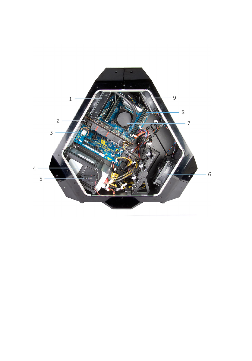
Right View
1 processor liquid-cooling
assembly-fan
3 system board 4 power-supply
5 AlienFX side-panel connector 6 PCI fan
7 processor liquid-cooling assembly
pump
9 memory fan (top fan)
2 graphics card
8 memory modules
15
Page 16
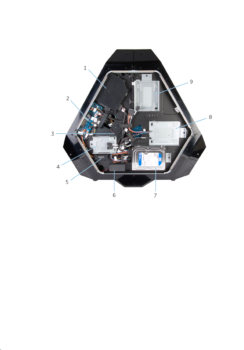
Left View
1 optical drive (ODD) 2 I/O board (IO BRD)
3 drive-bay heat-sensor 4 2.5 inch drive bracket (HDD4/
HDD5)
5 AlienFX side-panel connector 6 rear I/O accessibility lighting
batteries
7 3.5 inch drive bracket (HDD1) 8 3.5 inch drive bracket (HDD2)
9 3.5 inch drive bracket (HDD3)
16
Page 17
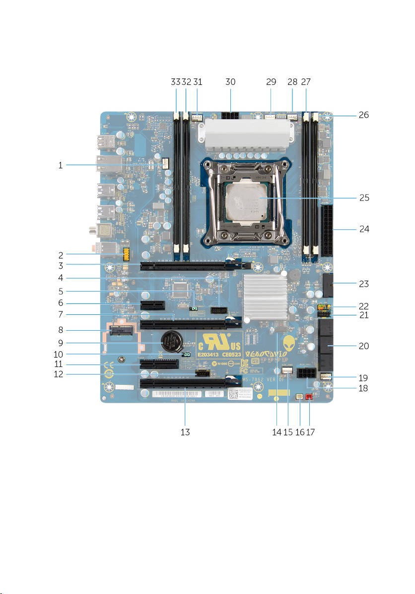
System-Board Components
1 processor liquid cooling-assembly
fan (LCM_FAN1)
3 PCI-Express x16 slot (SLOT1) 4 low pin count debug header
5 password reset jumper
(PASSWORD1)
2 audio connector (AUDIO101)
(LPC1)
6 PCI-Express x1 slot (SLOT2)
17
Page 18

7 PCI-Express x16 slot (SLOT3) 8 M.2 connector (wireless card)
9 coin-cell battery socket (BAT1) 10 CMOS reset jumper (CLEAR
CMOS1)
11 PCI-Express x4 slot (SLOT4) 12 Thunderbolt connector (TBT1)
13 PCI-Express x16 slot (SLOT5) 14 Serial Peripheral Interface
connector (SP11)
15 PCI-fan connector (SIDE_FAN1) 16 drive-bay heat-sensor
connector (SENSOR1)
17 chassis heat-sensor connector
(SENSOR2)
19 PCI-Express fan 1 connector
(PCI_FAN1)
21 USB connector (USB1) 22 LED Power Switch (PANEL1)
23 USB connector (USB3_MB1) 24 Advanced Technology xTended
25 processor socket (CPU1) 26 memory-module slot (DIMM3)
27 memory-module slot (DIMM4) 28 processor liquid-cooling
29 memory fan connector
(TOP_FAN1)
31 processor liquid-cooling assembly
pump-fan connector
(PUMP_FAN1)
33 memory-module slot (DIMM1)
18 PCI-Express power connector
(PCIE_PWR1)
20 SATA drive connectors
(ATX) power connector (ATX
PWR1)
assembly fan connector
(MID_FAN1)
30 processor-power connector
(CPU PWR1)
32 memory-module slot (DIMM2)
I/O Board Components
NOTE: The location of the connectors may vary based on the selections
you made at the time of purchase.
18
Page 19
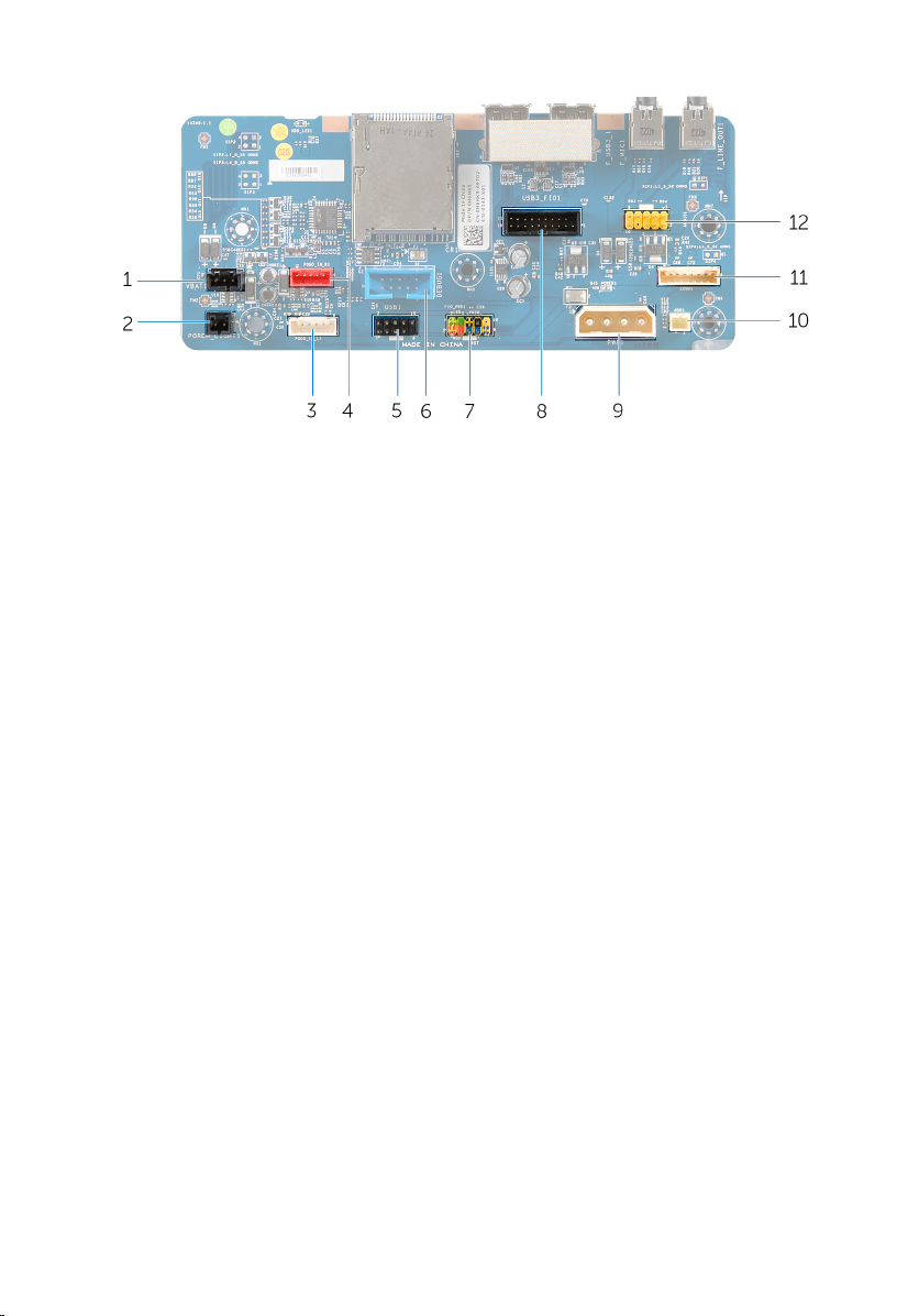
1 rear I/O accessibility lighting
battery connector (VBAT1)
2 rear I/O accessibility lighting
connector (PORCH_LIGHT1)
3 left theater-lighting connector
(POGO_IN_L1)
5 USB connector (USB1) 6 debug connector (DEBUG1)
7 front I/O control connector
(FIO_PWR1)
9 main-power connector (PWR1) 10 optical drive power connector
11 logo board connector (LOGO1) 12 audio connector (AUDIOIO1)
4 right theater-lighting connector
(POGO_IN_R1)
8 front I/O connector (USB3_FIO1)
(ODD1)
19
Page 20

Lifting the Computer
Procedure
1 With both hands, hold the handle on top of the computer.
20
Page 21
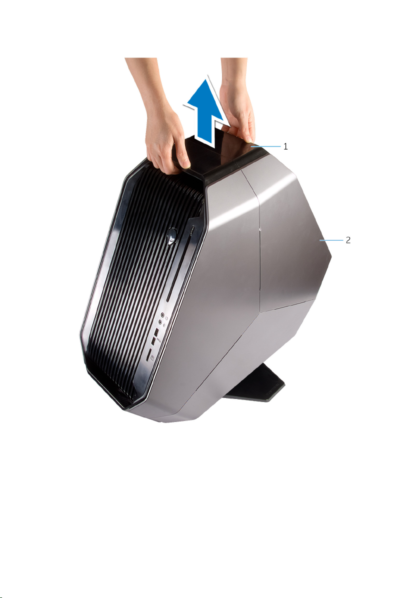
2 Lift the computer.
1 handle 2 computer
21
Page 22
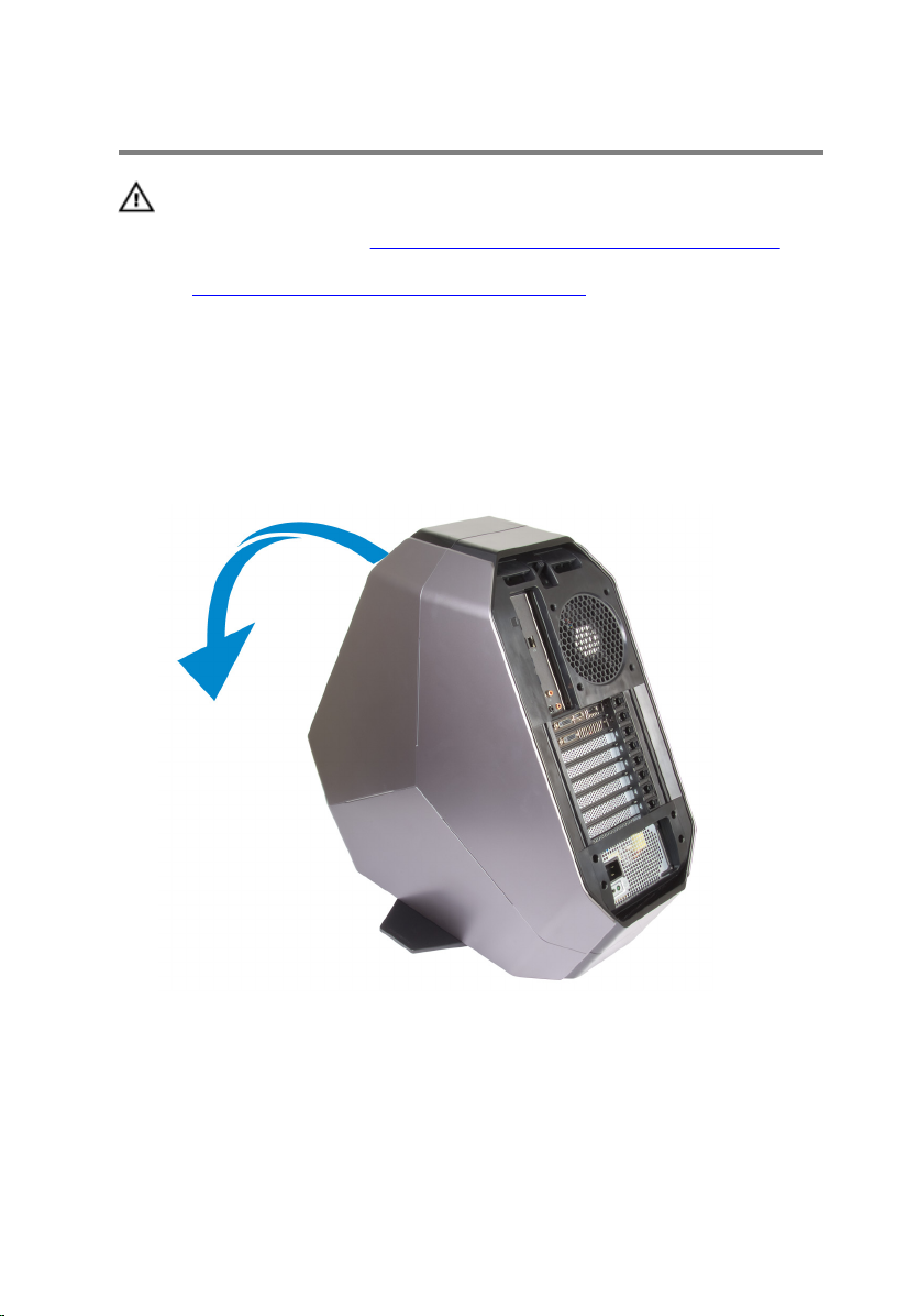
Removing the Stability Foot
WARNING: Before working inside your computer, read the
safety information that shipped with your computer and
follow the steps in
After working inside your computer, follow the instructions
in After Working Inside Your Computer. For more safety best
practices, see the Regulatory Compliance home page at
dell.com/regulatory_compliance.
Procedure
1 Tilt the computer towards the front until the base is facing up.
Before Working Inside Your Computer.
2 Remove the screws that secure the stability foot to the computer.
22
Page 23
3 Lift the stability foot off the computer.
1 stability foot 2 screws (2)
3 computer
23
Page 24
4 Tilt the computer back to the upright position.
24
Page 25

Replacing the Stability Foot
WARNING: Before working inside your computer, read the
safety information that shipped with your computer and
follow the steps in
After working inside your computer, follow the instructions
in After Working Inside Your Computer. For more safety best
practices, see the Regulatory Compliance home page at
dell.com/regulatory_compliance.
Procedure
1 Tilt the computer towards the front until the base is facing up.
2 Align the screw holes on the stability foot with the screw holes on the base
of the computer and replace the screws.
3 Tilt the computer back to the upright position.
Before Working Inside Your Computer.
25
Page 26
Removing the Side Panels
WARNING: Before working inside your computer, read the
safety information that shipped with your computer and
follow the steps in
After working inside your computer, follow the instructions
in After Working Inside Your Computer. For more safety best
practices, see the Regulatory Compliance home page at
dell.com/regulatory_compliance.
Procedure
NOTE: Make sure that you remove the security cable from the security
cable slot (if applicable).
1 Remove the screw that secures the security-cable slot latch.
The security-cable slot slides to the unlocked position.
2 Lift the release panel to open the right side-panel.
Before Working Inside Your Computer.
26
Page 27
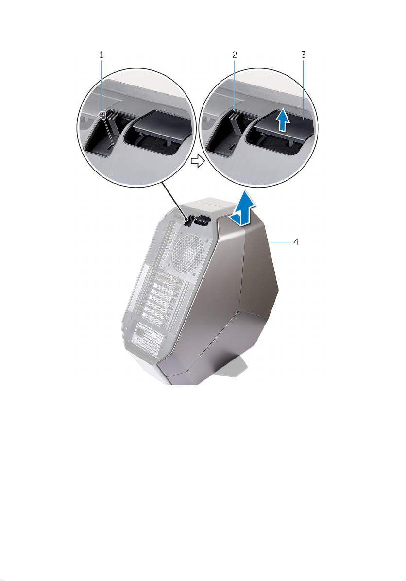
3 Pull and lift the right side-panel away from the chassis.
1 screw 2 security-cable slot latch
3 release panel 4 right side-panel
4 Repeat the procedure from step 2 to step 3 on the left side-panel.
27
Page 28
Replacing the Side Panels
WARNING: Before working inside your computer, read the
safety information that shipped with your computer and
follow the steps in
After working inside your computer, follow the instructions
in After Working Inside Your Computer. For more safety best
practices, see the Regulatory Compliance home page at
dell.com/regulatory_compliance.
Procedure
1 Align the tabs on the right side-panel with the slots on the right side of the
computer and snap the panel to lock it in place.
2 Repeat step 1 to replace the left side-panel.
3 Slide and hold the security-cable slot latch in the locked position.
4 Replace the screw that secures the security-cable slot latch.
Before Working Inside Your Computer.
28
Page 29
Removing the Battery
WARNING: Before working inside your computer, read the
safety information that shipped with your computer and
follow the steps in
After working inside your computer, follow the instructions
in After Working Inside Your Computer. For more safety best
practices, see the Regulatory Compliance home page at
dell.com/regulatory_compliance.
Prerequisites
Remove the right side-panel. See “Removing the Side Panels”.
Before Working Inside Your Computer.
29
Page 30
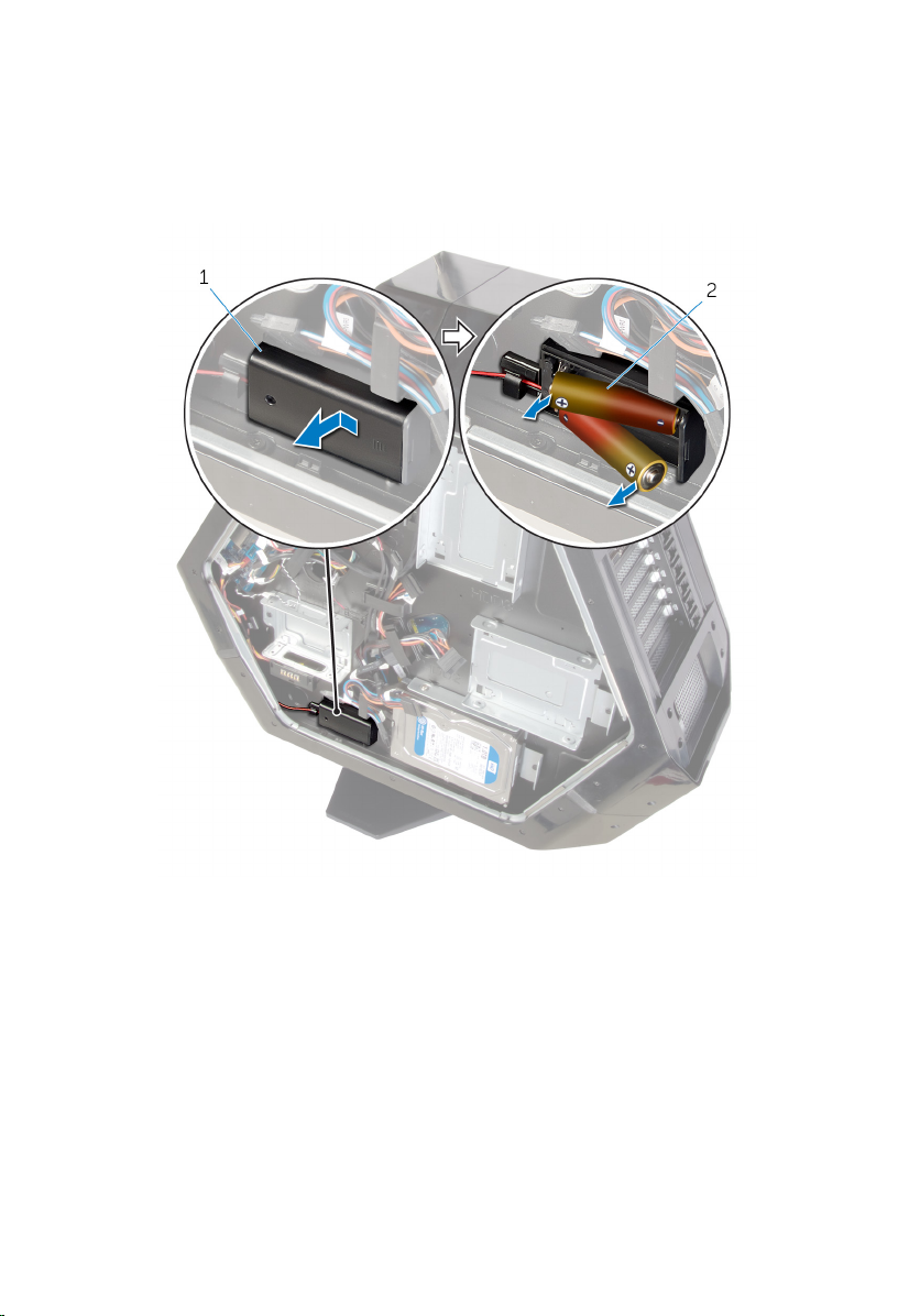
Procedure
Slide and open the battery-case door and remove the batteries from the
battery-case.
30
1 battery-case door 2 AA batteries (2)
Page 31

Replacing the Battery
WARNING: Before working inside your computer, read the
safety information that shipped with your computer and
follow the steps in
After working inside your computer, follow the instructions
in After Working Inside Your Computer. For more safety best
practices, see the Regulatory Compliance home page at
dell.com/regulatory_compliance.
Procedure
Insert the batteries and close the battery-case door.
Before Working Inside Your Computer.
31
Page 32

1 battery-case door 2 AA batteries (2)
Post-requisites
Replace the right side-panel. See “Replacing the Side Panels”.
32
Page 33

Removing the Battery Case
WARNING: Before working inside your computer, read the
safety information that shipped with your computer and
follow the steps in
After working inside your computer, follow the instructions
in After Working Inside Your Computer. For more safety best
practices, see the Regulatory Compliance home page at
dell.com/regulatory_compliance.
Prerequisites
1 Remove the stability foot.
2 Remove the right side-panel. See “Removing the Side Panels”.
Procedure
1 Lay the chassis on the right side.
2 Slide and open the battery-compartment door.
Before Working Inside Your Computer.
33
Page 34

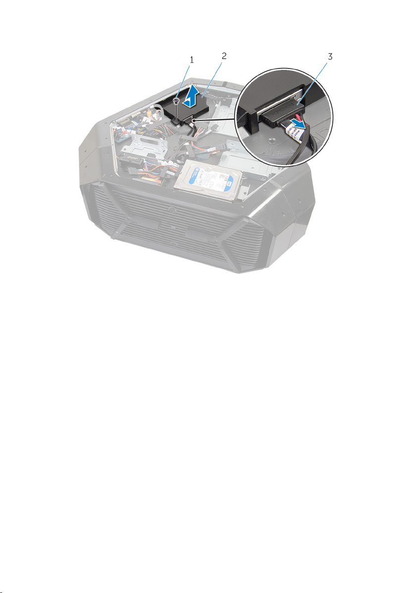
3 Remove the batteries from the battery-compartment.
1 battery-case door 2 AA batteries (2)
4 Press the releasing clips on the cable connector to disconnect the battery-
case cable from the chassis.
5 Remove the screws that secure the battery compartment to the chassis.
34
Page 35

6 Lift the battery-case off the chassis.
1 battery-case cable 2 battery-case connector
3 battery-case 4 screws (2)
35
Page 36

Replacing the Battery Case
WARNING: Before working inside your computer, read the
safety information that shipped with your computer and
follow the steps in
After working inside your computer, follow the instructions
in After Working Inside Your Computer. For more safety best
practices, see the Regulatory Compliance home page at
dell.com/regulatory_compliance.
Procedure
1 Align the screw holes on the battery-case with the screw holes on the
chassis.
2 Replace the screws that secure the battery-case to the chassis.
3 Connect the battery-case cable to the chassis.
4 Insert the batteries and close the battery-compartment door.
Post-requisites
1 Replace the right side-panel. See “Replacing the Side Panels”.
2 Replace the stability foot.
Before Working Inside Your Computer.
36
Page 37

Removing the Hard Drive
WARNING: Before working inside your computer, read the
safety information that shipped with your computer and
follow the steps in
After working inside your computer, follow the instructions
in After Working Inside Your Computer. For more safety best
practices, see the Regulatory Compliance home page at
dell.com/regulatory_compliance.
CAUTION: Hard drives are fragile. Exercise care when
handling the hard drive.
CAUTION: To avoid data loss, do not remove the hard drive
while the computer is in sleep or on state.
Prerequisites
1 Remove the stability foot.
2 Remove both the left and right side-panels. See “Removing the Side
Panels”.
Procedure
1 Lay the chassis on the right side.
2 Disconnect the power cable and data cable from the hard drive.
3 Remove the screw that secures the hard-drive assembly to the chassis.
Before Working Inside Your Computer.
37
Page 38

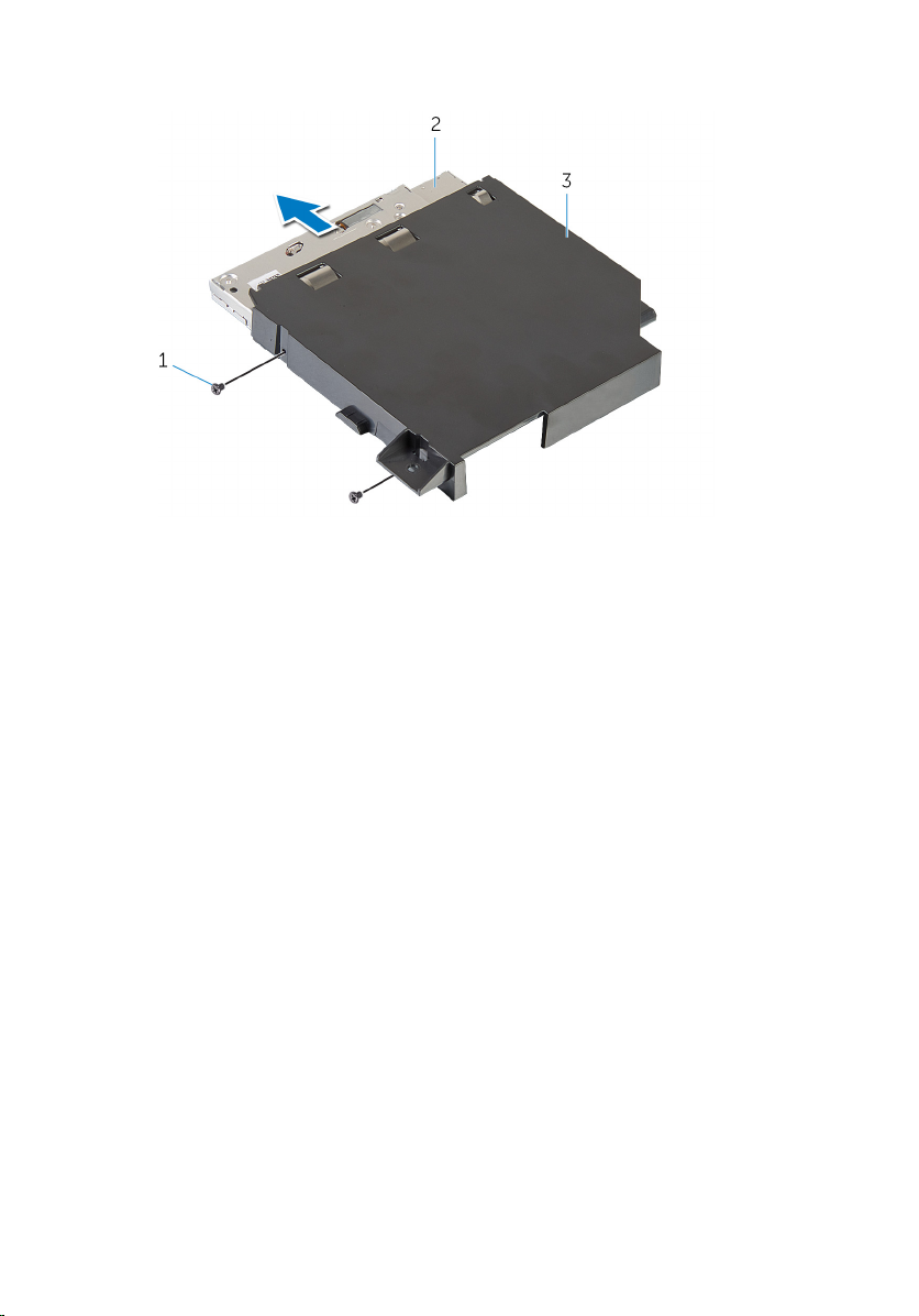
4 Using the tab, slide and remove the hard-drive assembly from the chassis.
1 power cable 2 data cable
3 chassis 4 screw
5 hard-drive assembly
5 Remove the screws that secure the hard-drive bracket to the hard drive.
38
Page 39

6 Slide and remove the hard drive from the hard-drive bracket.
NOTE: Repeat step 2 to step 5 to remove any other hard drives
installed in your computer.
1 screws (4) 2 hard drive
3 hard-drive bracket
39
Page 40

Replacing the Hard Drive
WARNING: Before working inside your computer, read the
safety information that shipped with your computer and
follow the steps in
After working inside your computer, follow the instructions
in After Working Inside Your Computer. For more safety best
practices, see the Regulatory Compliance home page at
dell.com/regulatory_compliance.
CAUTION: Hard drives are fragile. Exercise care when
handling the hard drive.
Procedure
1 Align the screw holes on the hard-drive bracket with the screw holes on
the hard drive.
2 Replace the screws that secures the hard drive to the hard-drive bracket.
3 Place the hard-drive assembly in the chassis.
4 Replace the screws that secure the hard-drive assembly to the chassis.
5 Connect the power cable and data cable to the hard-drive.
NOTE: Repeat step 2 to step 5 to replace any other hard drives
installed in your computer.
Before Working Inside Your Computer.
Post-requisites
1 Replace both the left and right side-panels. See “Replacing the Side
Panels”.
2 Replace the stability foot.
40
Page 41

Removing the Optical Drive
WARNING: Before working inside your computer, read the
safety information that shipped with your computer and
follow the steps in
After working inside your computer, follow the instructions
in After Working Inside Your Computer. For more safety best
practices, see the Regulatory Compliance home page at
dell.com/regulatory_compliance.
Prerequisites
1 Remove the stability foot.
2 Remove both the left and right side-panels. See “Removing the Side
Panels”.
Procedure
1 Lay the chassis on the right side.
2 Disconnect the power and data cable from the optical drive.
3 Remove the screw that secures the optical-drive assembly to the chassis.
Before Working Inside Your Computer.
41
Page 42
4 Slide and lift the optical-drive assembly of the chassis.
1 screw 2 optical-drive assembly
3 data cable and power cable
5 Remove the screws that secure the optical-drive bracket to the optical
drive.
42
Page 43
6 Slide and remove the optical drive from the optical-drive bracket.
1 screws (2) 2 optical drive
3 optical-drive bracket
43
Page 44

Replacing the Optical Drive
WARNING: Before working inside your computer, read the
safety information that shipped with your computer and
follow the steps in
After working inside your computer, follow the instructions
in After Working Inside Your Computer. For more safety best
practices, see the Regulatory Compliance home page at
dell.com/regulatory_compliance.
Procedure
1 Align the screw holes on the optical-drive bracket with the screw holes on
the optical drive.
2 Replace the screws that secures the optical drive to the optical-drive
bracket.
3 Align the screw holes on the optical-drive assembly with the screw holes
on the chassis.
4 Replace the screws that secure the optical-drive bay assembly to the
chassis.
5 Plug the power cable and data cable to the optical drive.
Post-requisites
Before Working Inside Your Computer.
1 Replace both the left and right side-panels. See “Replacing the Side
Panels”.
2 Replace the stability foot.
44
Page 45

Removing the Right AlienFX Side-Panel Connector
WARNING: Before working inside your computer, read the
safety information that shipped with your computer and
follow the steps in
After working inside your computer, follow the instructions
in After Working Inside Your Computer. For more safety best
practices, see the Regulatory Compliance home page at
dell.com/regulatory_compliance.
Prerequisites
1 Remove the stability foot.
2 Remove both the left and right side-panels. See “Removing the Side
Panels”.
Procedure
1 Lay the chassis on the left side.
2 Disconnect the cable that connects the right AlienFX side-panel connector
to the I/O board. See “I/O Board Components”.
3 Remove the screw that secures the right AlienFX side-panel connector
assembly to the chassis.
Before Working Inside Your Computer.
45
Page 46
4 Remove the right AlienFX side-panel connector assembly from the chassis.
46
1 screw 2 right AlienFX side-panel
connector assembly
3 AlienFX side-panel cable 4 AlienFX side-panel
connector
Page 47
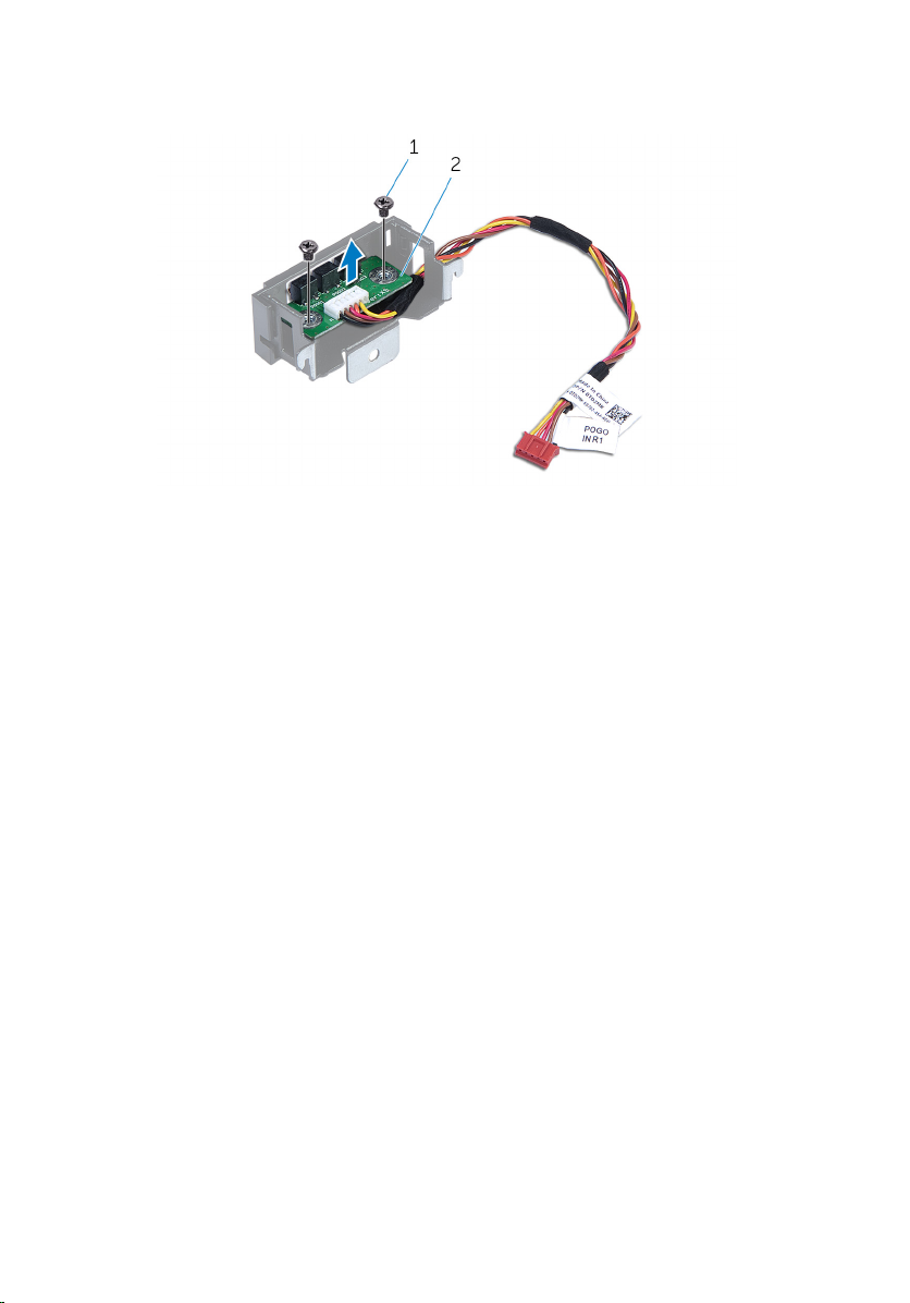
5 Remove the screws that secure the right AlienFX side-panel connector to
the bracket and set it aside in a secure location.
1 screws (2) 2 right AlienFX side-panel
connector
47
Page 48

Replacing the Right AlienFX Side-Panel Connector
WARNING: Before working inside your computer, read the
safety information that shipped with your computer and
follow the steps in
After working inside your computer, follow the instructions
in After Working Inside Your Computer. For more safety best
practices, see the Regulatory Compliance home page at
dell.com/regulatory_compliance.
Procedure
1 Replace the screws that secure the right AlienFX side-panel connector to
the bracket.
2 Replace the screws that secure the right AlienFX side-panel connector to
the chassis.
3 Connect the cable that connects the right AlienFX side-panel connector to
the I/O board. See “I/O Board Components”.
Post-requisites
Before Working Inside Your Computer.
1 Replace both the left and right side-panels. See “Replacing the Side
Panels”.
2 Replace the stability foot.
48
Page 49

Removing the Left AlienFX Side-Panel Connector
WARNING: Before working inside your computer, read the
safety information that shipped with your computer and
follow the steps in
After working inside your computer, follow the instructions
in After Working Inside Your Computer. For more safety best
practices, see the Regulatory Compliance home page at
dell.com/regulatory_compliance.
Prerequisites
1 Remove the stability foot.
2 Remove both the left and right side-panels. See “Removing the Side
Panels”.
Procedure
1 Lay the chassis on the left side.
Before Working Inside Your Computer.
49
Page 50

2 Disconnect the cable that connects the left AlienFX side-panel connector
to the I/O board.
1 AlienFX side-panel
connector
3 I/O board
3 Turn the chassis over.
4 Remove the AlienFX side-panel cable through the routing holes.
5 Remove the screw that secures the left AlienFX side-panel connector
assembly to the chassis.
50
2 left AlienFX side-panel
cable
Page 51
6 Remove the left AlienFX side-panel connector assembly from the chassis.
1 screw 2 left AlienFX side-panel
connector assembly
51
Page 52

7 Remove the screws that secure the AlienFX side-panel connector to the
bracket and set it aside in a secure location.
1 screw 2 left AlienFX side-panel
connector
52
Page 53

Replacing the Left AlienFX Side-Panel Connector
WARNING: Before working inside your computer, read the
safety information that shipped with your computer and
follow the steps in
After working inside your computer, follow the instructions
in After Working Inside Your Computer. For more safety best
practices, see the Regulatory Compliance home page at
dell.com/regulatory_compliance.
Procedure
1 Replace the screws that secure the left AlienFX side-panel connector to the
bracket.
2 Replace the screws that secure the left AlienFX side-panel connector to the
chassis.
3 Connect the cable that connects the left AlienFX side-panel connector to
the system board.
Post-requisites
Before Working Inside Your Computer.
1 Replace both the left and right side-panels. See “Replacing the Side
Panels”.
2 Replace the stability foot.
53
Page 54

Removing the I/O Board
WARNING: Before working inside your computer, read the
safety information that shipped with your computer and
follow the steps in
After working inside your computer, follow the instructions
in After Working Inside Your Computer. For more safety best
practices, see the Regulatory Compliance home page at
dell.com/regulatory_compliance.
Prerequisites
1 Remove the stability foot.
2 Remove the left and right side-panels. See “Removing the Side Panels”.
Procedure
1 Lay the system on the right side.
Before Working Inside Your Computer.
54
Page 55
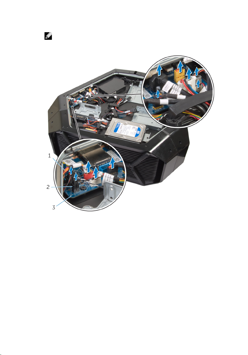
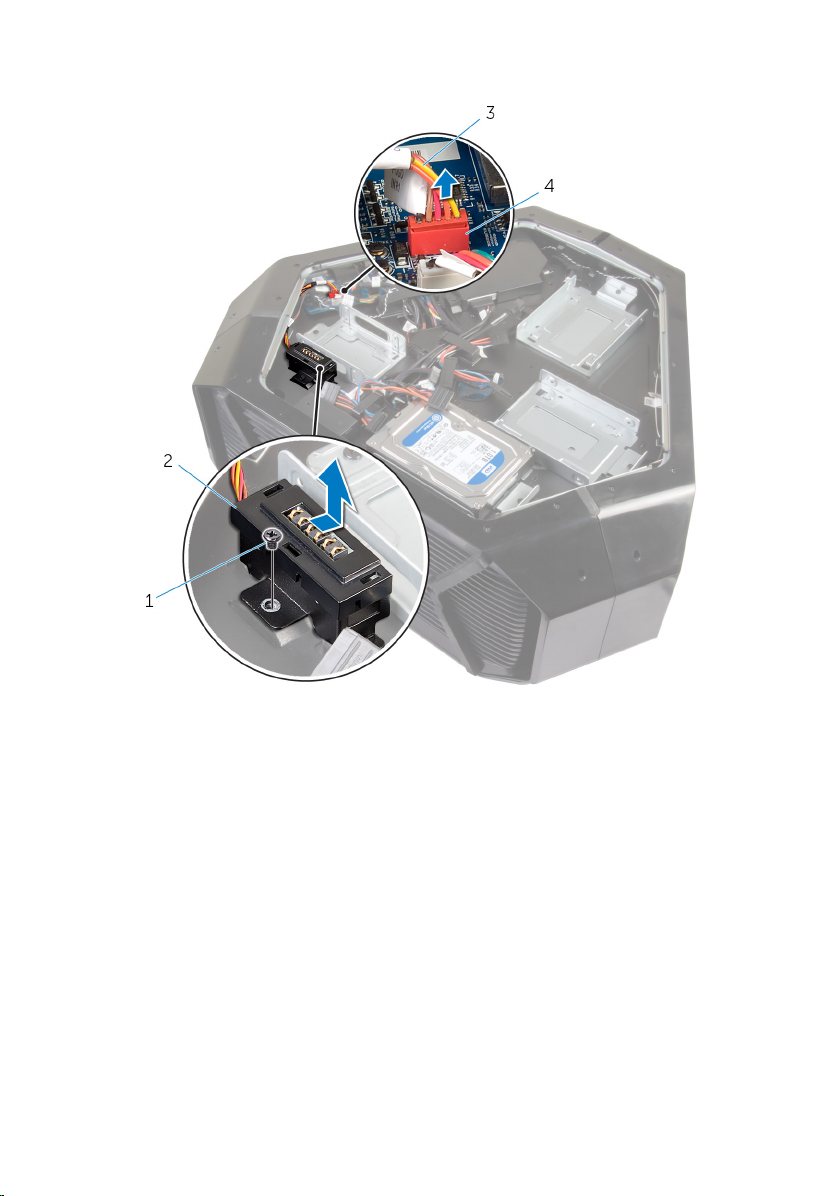
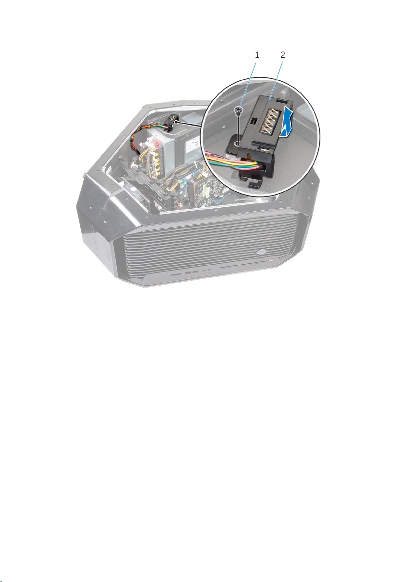
2 Disconnect all cables from the connectors on the I/O board.
NOTE: Note the routing of all cables as you remove them so that you
can reroute them correctly after you replace the I/O board.
1 cables 2 connector
3 I/O board
3 Remove the screws that secure the I/O board to the chassis.
55
Page 56

4 Remove the I/O board out of the chassis.
1 I/O board 2 screws (2)
56
Page 57

Replacing the I/O Board
WARNING: Before working inside your computer, read the
safety information that shipped with your computer and
follow the steps in
After working inside your computer, follow the instructions
in After Working Inside Your Computer. For more safety best
practices, see the Regulatory Compliance home page at
dell.com/regulatory_compliance.
Procedure
1 Align the screw holes on the I/O board to the screw holes on the chassis
and place the I/O board in the chassis.
2 Replace the screws that secure the master I/O board to the chassis.
3 Route and connect the cables that you removed from the connectors on
the I/O board.
NOTE: The connectors on the I/O board are color coded. Make sure
that you match the color of the I/O board connector with the cable
connector. For more information on I/O connectors, see
Components”.
Post-requisites
Before Working Inside Your Computer.
I/O Board
1 Replace the left and right side-panels. See “Replacing the Side Panels”.
2 Replace the stability foot.
57
Page 58

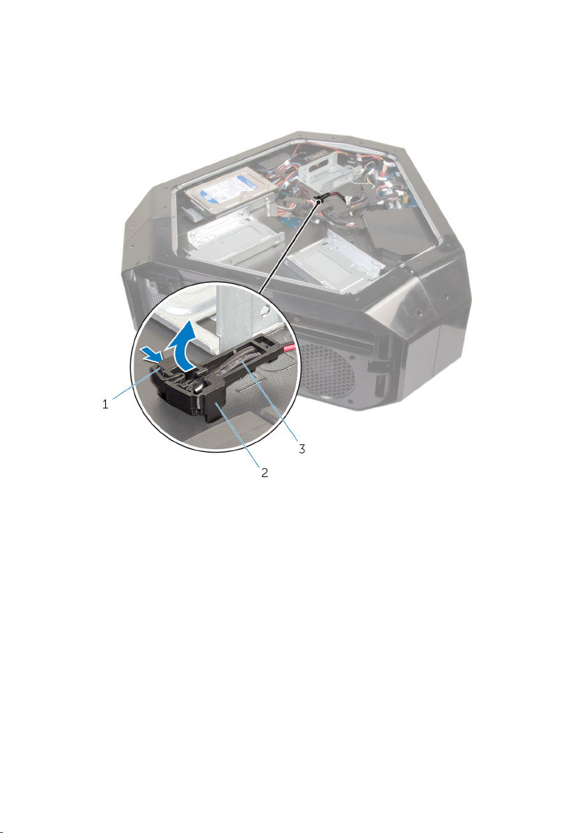
Removing the Drive-Bay Heat-Sensor
WARNING: Before working inside your computer, read the
safety information that shipped with your computer and
follow the steps in
After working inside your computer, follow the instructions
in After Working Inside Your Computer. For more safety best
practices, see the Regulatory Compliance home page at
dell.com/regulatory_compliance.
Prerequisites
1 Remove the stability foot.
2 Remove both the left and right side-panels. See “Removing the Side
Panels”.
Procedure
1 Lay the chassis on the left side.
2 Locate the drive-bay heat-sensor connector (SENSOR1) on the system
board. For more information on the drive-bay heat-sensor connector, see
System-Board Components”.
“
Before Working Inside Your Computer.
58
Page 59

3 Disconnect the drive-bay heat-sensor cable from the connector on the
system board.
1 drive-bay heat-sensor
connector
3 drive-bay heat-sensor cable
4 Turn the chassis over.
5 Remove the cable through the sensor bracket.
6 Locate the drive-bay heat-sensor. See “Left View”.
7 Press the release tab on the securing clip.
8 Pry out the drive-bay heat-sensor cable from the securing clip.
2 drive-bay heat-sensor
cable connector
59
Page 60
9 Slide the drive-bay heat-sensor cable out of the sensor bracket.
60
1 release tab 2 securing clip
3 drive-bay heat-sensor cable
Page 61

Replacing the Drive-Bay Heat-Sensor
WARNING: Before working inside your computer, read the
safety information that shipped with your computer and
follow the steps in
After working inside your computer, follow the instructions
in After Working Inside Your Computer. For more safety best
practices, see the Regulatory Compliance home page at
dell.com/regulatory_compliance.
Procedure
1 Reroute the drive-bay heat-sensor in the sensor bracket.
2 Align the drive-bay heat-sensor in the securing clip.
3 Close and press the release tab on the securing clip.
4 Lay the chassis on the left side.
5 Connect the drive-bay heat-sensor cable to the connector on the system
board. See “System Board Components”.
Post-requisites
Before Working Inside Your Computer.
1 Replace both the left and right side-panels. See “Replacing the Side
Panels”.
2 Replace the stability foot.
61
Page 62

Removing the Memory Module(s)
WARNING: Before working inside your computer, read the
safety information that shipped with your computer and
follow the steps in
After working inside your computer, follow the instructions
in After Working Inside Your Computer. For more safety best
practices, see the Regulatory Compliance home page at
dell.com/regulatory_compliance.
Prerequisites
1 Remove the stability foot.
2 Remove both the left and right side-panels. See “Removing the Side
Panels”.
Procedure
1 Lay the computer on the left side.
2 Locate the memory modules on the system board. For more information
on the memory modules see “System-Board Components”.
3 Push the securing clips away from the memory module.
Before Working Inside Your Computer.
62
Page 63

4 Grasp the memory module near the securing clip, and then gently ease the
memory module out of the memory-module slot.
NOTE: Repeat step 2 to step 3 to remove any other memory modules
installed in your computer.
1 securing clips (2) 2 memory module
3 memory-module slot
63
Page 64

Replacing the Memory Module(s)
WARNING: Before working inside your computer, read the
safety information that shipped with your computer and
follow the steps in
After working inside your computer, follow the instructions
in After Working Inside Your Computer. For more safety best
practices, see the Regulatory Compliance home page at
dell.com/regulatory_compliance.
Procedure
1 Align the notch on the bottom of the memory module with the tab on the
memory-module slot.
Before Working Inside Your Computer.
64
Page 65

2 Insert the memory module into the memory-module connector until the
memory module snaps into position and the securing clips lock in place.
NOTE: If you do not hear the click, remove the memory module and
reinstall it.
1 memory module 2 memory-module slot
3 notch
Post-requisites
1 Remove both the left and right side-panels. See “Removing the Side
Panels”.
2 Replace the stability foot.
65
Page 66

Removing the Graphics Card
WARNING: Before working inside your computer, read the
safety information that shipped with your computer and
follow the steps in
After working inside your computer, follow the instructions
in After Working Inside Your Computer. For more safety best
practices, see the Regulatory Compliance home page at
dell.com/regulatory_compliance.
Prerequisites
1 Remove the stability foot.
2 Remove both the left and right side-panels. See “Removing the Side
Panels”.
Procedure
1 Lay the computer on the right side.
2 Locate the graphics card (PCI-Express x16 card) on the system board. For
more information on graphics card see “System Board Components”.
3 Press and push the screw covers covering the screws that secure the
graphics card.
4 Remove the screws that secure the graphics card to the chassis.
Before Working Inside Your Computer.
66
Page 67

5 Press the releasing clips on the power-cable connectors to disconnect the
power cables from the graphics card.
NOTE: The location of the power supply connector varies depending
on the video card installed.
1 screw cover 2 screws (2)
3 graphics card 4 power cables (2)
67
Page 68

6 Press and hold the securing tab on the card connector, grasp the card by
its top corners, and then ease the card out of the slot.
1 graphics card 2 releasing clips
68
Page 69

Replacing the Graphics Card
WARNING: Before working inside your computer, read the
safety information that shipped with your computer and
follow the steps in
After working inside your computer, follow the instructions
in After Working Inside Your Computer. For more safety best
practices, see the Regulatory Compliance home page at
dell.com/regulatory_compliance.
Procedure
1 Align the graphics card with the PCI-Express x16 card connector on the
system board.
2 Place the card in the connector and press down firmly. Ensure that the
card is firmly seated.
3 Replace the screws that secure the graphics card to the chassis.
4 Connect the power cables to the graphics card.
NOTE: The location of the power supply connector varies depending
on the video card installed.
5 From outside the chassis, push the screw covers inside to cover the screws
that secure the graphics card.
Before Working Inside Your Computer.
Post-requisites
1 Replace both the left and right side-panels. See “Replacing the Side
Panels”.
2 Replace the stability foot.
69
Page 70

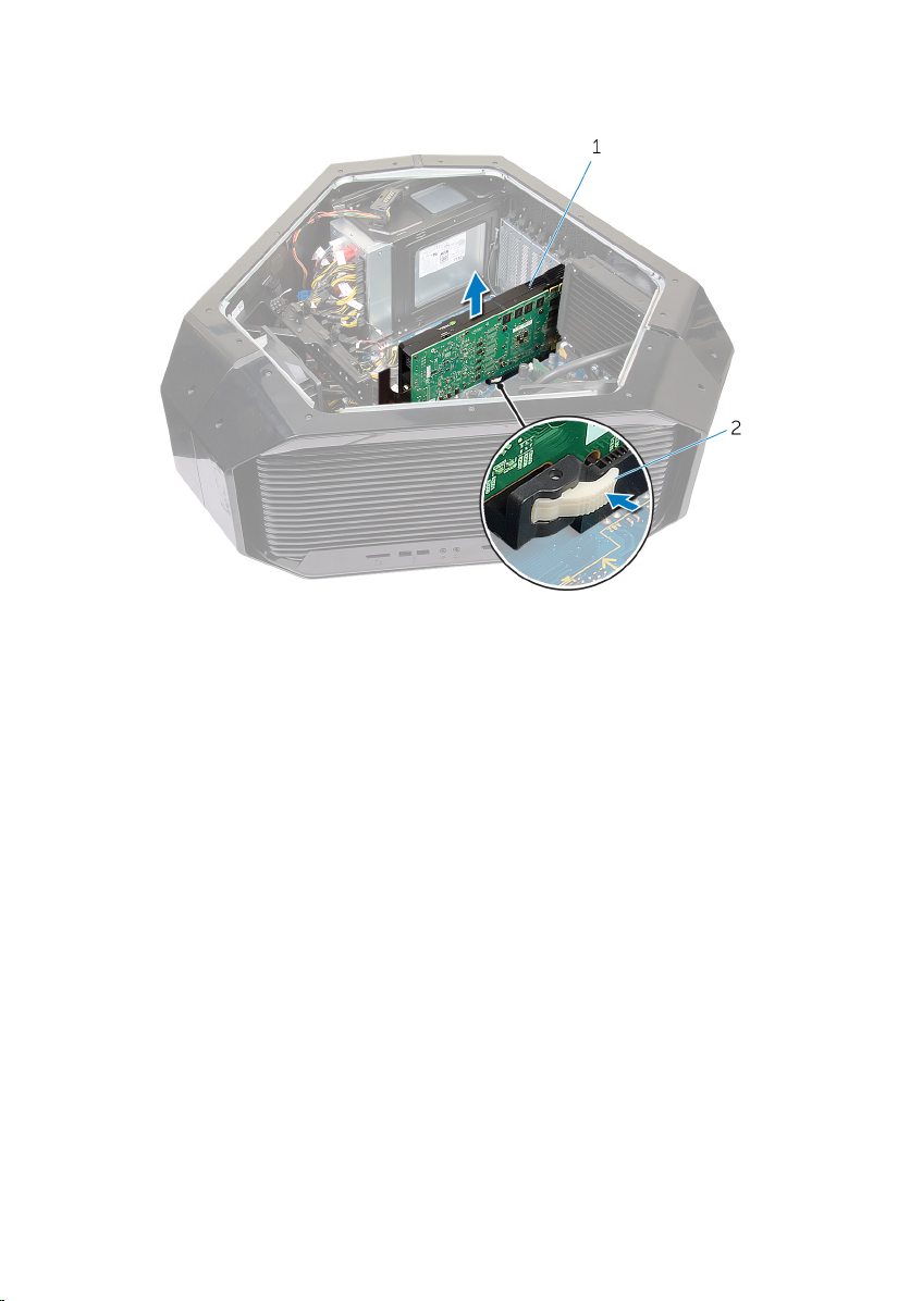
Removing the Multiple Graphics Cards
WARNING: Before working inside your computer, read the
safety information that shipped with your computer and
follow the steps in
After working inside your computer, follow the instructions
in After Working Inside Your Computer. For more safety best
practices, see the Regulatory Compliance home page at
dell.com/regulatory_compliance.
Prerequisites
1 Remove the stability foot.
2 Remove both the left and right side-panels. See “Removing the Side
Panels”.
Procedure
1 Lay the chassis on the left side.
2 Locate the graphics cards (PCI-Express x16 card) on the system board. For
more information on the graphics card connector, see “System Board
Components”.
Before Working Inside Your Computer.
70
Page 71

3 Remove the graphics bridge that connects the graphics cards.
1 graphics bridge
4 Starting with the graphics card on the PCI-Express x16 card SLOT1, press
and push the screw covers covering the screws that secure the graphics
card.
5 Remove the screws that secure the graphics card to the chassis.
71
Page 72

6 Press the releasing clips on the power-cable connectors to disconnect the
power cables from the graphics card.
NOTE: The location of the power supply connector varies depending
on the video card installed.
72
1 screw cover 2 screws (2)
3 power cables (2)
Page 73

7 Press and hold the securing tab on the card connector, grasp the card by
its top corners, and then ease the card out of the card connector.
1 graphics card 2 releasing clips
8 Repeat steps 2 to 5 to remove graphics card on the PCI-Express x16 card
connector (SLOT3) and PCI-Express x16 card connector (SLOT5).
73
Page 74

Replacing the Multiple Graphics Cards
WARNING: Before working inside your computer, read the
safety information that shipped with your computer and
follow the steps in
After working inside your computer, follow the instructions
in After Working Inside Your Computer. For more safety best
practices, see the Regulatory Compliance home page at
dell.com/regulatory_compliance.
Procedure
1 Locate the graphics (PCI-Express x16 (SLOT5)) connector on the system
board. For more information on the graphics connector, see “System Board
Components”.
2 Align the graphics card with the PCI-Express x16 card connector (SLOT5) on
the system board.
3 Place the card in the connector and press down firmly. Ensure that the
card is firmly seated in the slot.
NOTE: Repeat steps 2 to 3 to install graphics card on the PCI-Express
x16 card connector (SLOT3) and PCI-Express x16 card connector
(SLOT1).
4 Replace the screws that secure the graphics card to the chassis.
5 Connect the graphics bridge that connects the graphics cards.
6 Connect the power cables to the graphics card.
Before Working Inside Your Computer.
NOTE: The location of the power supply connector varies depending
on the video card installed.
7 From outside the chassis, push the screw covers inside to cover the screws
that secure the graphics card.
Post-requisites
1 Replace both the left and right side-panels. See “Replacing the Side
Panels”.
2 Replace the stability foot.
74
Page 75

Removing the Full-length Graphics Cards
WARNING: Before working inside your computer, read the
safety information that shipped with your computer and
follow the steps in
After working inside your computer, follow the instructions
in After Working Inside Your Computer. For more safety best
practices, see the Regulatory Compliance home page at
dell.com/regulatory_compliance.
Prerequisites
1 Remove the stability foot.
2 Remove both the left and right side-panels. See “Removing the Side
Panels”.
Procedure
1 Lay the computer on the right side.
2 Locate the graphics (PCI-Express x16) connector on the system board. For
more information on the graphics connector, see “System Board
Components”.
3 Press and hold the securing tab on the clamp.
Before Working Inside Your Computer.
75
Page 76

4 Pull the clamp away from the bracket.
1 clamp 2 bracket
5 Press and push the screw covers covering the screws that secure the
graphics card.
6 Remove the screws that secure the graphics card to the chassis.
76
Page 77

7 Press the releasing clips on the power-cable connectors to disconnect the
power cables from the graphics card.
NOTE: The location of the power supply connector varies depending
on the video card installed.
1 screw cover 2 screws (2)
3 power cables (2)
77
Page 78
8 Press and hold the securing tab on the card connector, grasp the card by
its top corners, and then ease the card out of the card connector.
1 graphics card 2 releasing clips
78
Page 79

Replacing the Full-length Graphics Cards
WARNING: Before working inside your computer, read the
safety information that shipped with your computer and
follow the steps in
After working inside your computer, follow the instructions
in After Working Inside Your Computer. For more safety best
practices, see the Regulatory Compliance home page at
dell.com/regulatory_compliance.
Procedure
1 Align the graphics card with the PCI-Express x16 card connector on the
system board.
2 Place the card in the connector and press down firmly. Ensure that the
card is firmly seated.
3 Press and hold the securing tab on the clamp.
4 Push the clamp back into the bracket.
5 Replace the screws that secure the graphics card to the chassis.
6 Connect the power cables to the graphics card.
NOTE: The location of the power supply connector varies depending
on the video card installed.
7 From outside the chassis, push the screw covers inside to cover the screws
that secure the graphics card.
Before Working Inside Your Computer.
Post-requisites
1 Replace both the left and right side-panels. See “Replacing the Side
Panels”.
2 Replace the stability foot.
79
Page 80

Removing the PCI Fan
WARNING: Before working inside your computer, read the
safety information that shipped with your computer and
follow the steps in
After working inside your computer, follow the instructions
in After Working Inside Your Computer. For more safety best
practices, see the Regulatory Compliance home page at
dell.com/regulatory_compliance.
Prerequisites
1 Remove the stability foot.
2 Remove both the left and right side-panels. See “Removing the Side Panel”.
Procedure
1 Lay the chassis on the left side.
Before Working Inside Your Computer.
80
Page 81

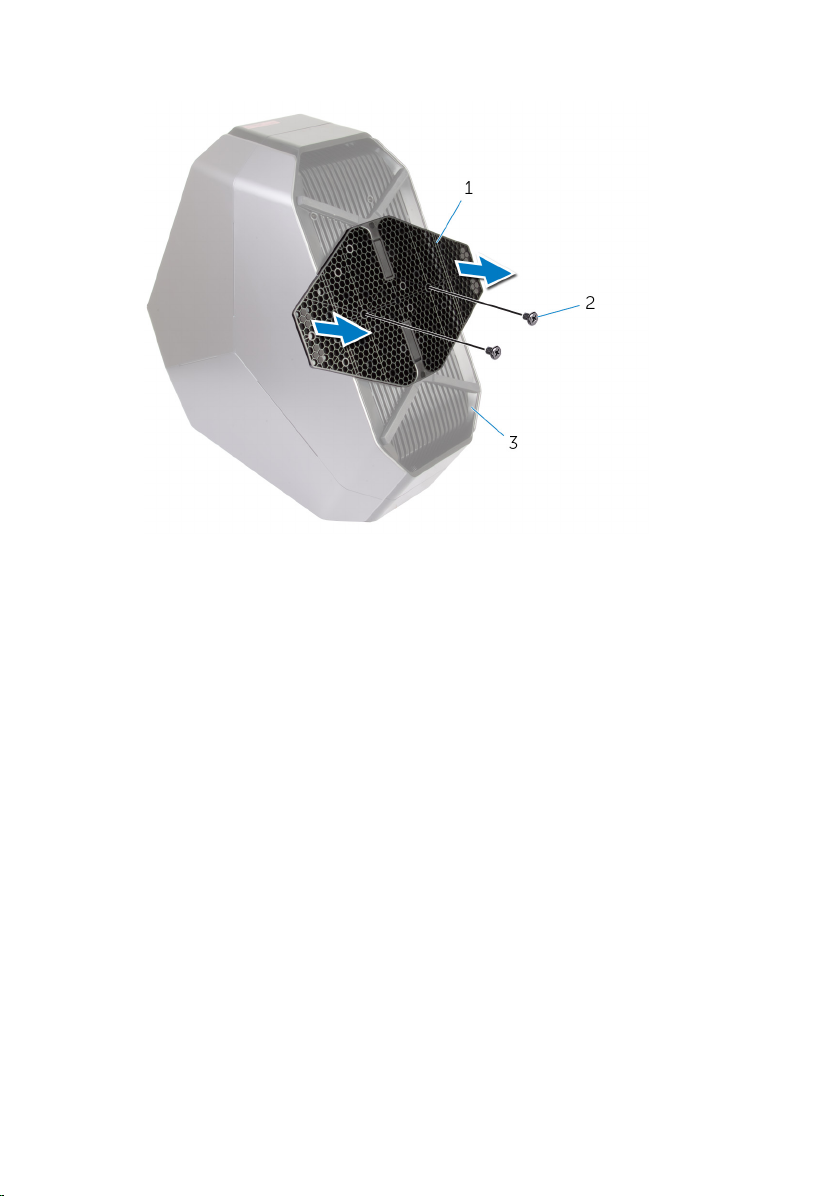
2 Remove the screws that secure the graphics-card bracket to the chassis.
1 screws (4) 2 graphics-card bracket
81
Page 82

3 Remove the screws that secure the PCI fan to the chassis.
1 PCI fan 2 screws (2)
4 Disconnect the PCI-fan cable and front-bezel heat-sensor cable from the
connector on the system board.
82
Page 83

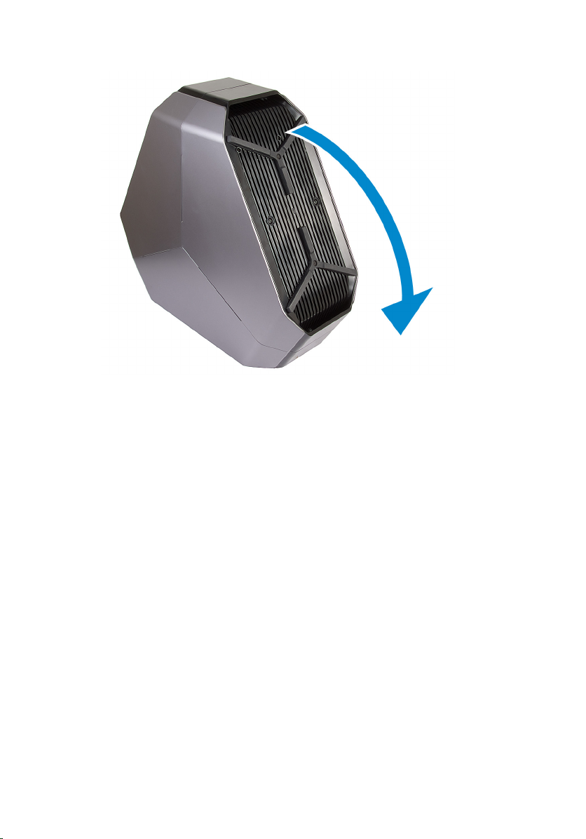
5 Pry out the PCI fan from the tabs securing it to the chassis.
1 tabs 2 PCI fan
3 PCI-fan cable 4 front-bezel heat-sensor
5 PCI-fan connector
6 Remove the screws securing the fan shroud to the PCI fan.
83
Page 84

7 Pry out the PCI fan from the fan shroud by lifting the fan shroud upwards.
1 screws (4) 2 fan shroud
84
Page 85

Replacing the PCI Fan
WARNING: Before working inside your computer, read the
safety information that shipped with your computer and
follow the steps in
After working inside your computer, follow the instructions
in After Working Inside Your Computer. For more safety best
practices, see the Regulatory Compliance home page at
dell.com/regulatory_compliance.
Procedure
1 Align the tabs on the fan shroud with the slots on the PCI fan and snap the
fan shroud in place.
2 Replace the screws securing the fan shroud to the PCI fan.
3 Align the tabs on the PCI-fan shroud with the slots on the chassis and slide
the fan until it snaps into position.
4 Connect the PCI-fan cable and front-bezel heat-sensor cable to the
connectors on the system board.
5 Replace the screws that secure the PCI fan to the chassis.
6 Align the screw holes on the on the graphics-card bracket with the screw
holes on the chassis.
7 Replace the screws that secure the graphics-card bracket to the chassis.
Before Working Inside Your Computer.
Post-requisites
1 Replace both the left and right side-panels. See “Replacing the Side
Panels”.
2 Replace the stability foot.
85
Page 86

Removing the Front-bezel Heat-sensor
WARNING: Before working inside your computer, read the
safety information that shipped with your computer and
follow the steps in
After working inside your computer, follow the instructions
in After Working Inside Your Computer. For more safety best
practices, see the Regulatory Compliance home page at
dell.com/regulatory_compliance.
Prerequisites
1 Remove the stability foot.
2 Remove both the left and right side-panels. See “Removing the Side
Panels”.
3 Remove the PCI fan. See “Removing the PCI fan”.
Procedure
NOTE: After removing the PCI fan, locate the sensor on the fan shroud.
Before Working Inside Your Computer.
1 Lay the computer on the left side.
2 Press the release tab on the securing clip.
3 Pry out the chassis heat-sensor cable from the securing clip.
86
Page 87

4 Slide the chassis heat-sensor cable out of the bracket.
1 chassis heat-sensor cable 2 securing clip
3 release tab 4 fan shroud
87
Page 88

Replacing the Front-bezel Heat-sensor
WARNING: Before working inside your computer, read the
safety information that shipped with your computer and
follow the steps in
After working inside your computer, follow the instructions
in After Working Inside Your Computer. For more safety best
practices, see the Regulatory Compliance home page at
dell.com/regulatory_compliance.
Procedure
1 Reroute the chassis heat-sensor in the bracket.
2 Align the chassis heat-sensor in the securing clip.
3 Close and press the release tab on the securing clip.
Post-requisites
1 Replace the PCI fan.
2 Replace both the left and right side-panels. See “Replacing the Side
Panels”.
3 Replace the stability foot.
Before Working Inside Your Computer.
88
Page 89

Removing the Memory Fan
WARNING: Before working inside your computer, read the
safety information that shipped with your computer and
follow the steps in
After working inside your computer, follow the instructions
in After Working Inside Your Computer. For more safety best
practices, see the Regulatory Compliance home page at
dell.com/regulatory_compliance.
Prerequisites
1 Remove the stability foot.
2 Remove both the left and right side-panels. See “Removing the Side
Panels”.
Procedure
1 Lay the computer on the right side.
2 Disconnect the memory-fan cable from the connector on the system
board. For more information on the memory-fan cable connector, see
System Board Components”.
“
3 Remove the screw that secures the memory fan on the chassis.
4 Pull the release tab away from the chassis and move the fan towards the
right side.
Before Working Inside Your Computer.
89
Page 90

5 Lift the memory fan out of the chassis.
1 memory-fan 2 release tab
3 screw 4 memory-fan cable
90
Page 91

Replacing the Memory Fan
WARNING: Before working inside your computer, read the
safety information that shipped with your computer and
follow the steps in
After working inside your computer, follow the instructions
in After Working Inside Your Computer. For more safety best
practices, see the Regulatory Compliance home page at
dell.com/regulatory_compliance.
Procedure
1 Align the tabs on the memory fan with the slots on the chassis and slide
the fan until it snaps into position.
2 Replace the screw that secures the memory fan on the chassis.
3 Connect the memory fan cable from the connector on the system board.
For more information on the memory fan cable connector, see “
Board Components”.
Post-requisites
1 Replace both the left and right side-panels. See “Replacing the Side
Panels”.
2 Replace the stability foot.
Before Working Inside Your Computer.
System
91
Page 92

Removing the Processor Cooling-Assembly
WARNING: Before working inside your computer, read the
safety information that shipped with your computer and
follow the steps in
After working inside your computer, follow the instructions
in After Working Inside Your Computer. For more safety best
practices, see the Regulatory Compliance home page at
dell.com/regulatory_compliance.
Prerequisites
1 Remove the stability foot.
2 Remove both the left and right side-panels. See “Removing the Side Panel”.
Procedure
WARNING: Despite having a plastic shield, the processor
liquid-cooling assembly may be very hot during normal
operation. Ensure that it had sufficient time to cool before
you touch it.
CAUTION: To ensure maximum cooling for the processor, do
not touch the heat transfer areas on the processor liquidcooling assembly. The oils in your skin can reduce the heat
transfer capability of the thermal grease.
Before Working Inside Your Computer.
1 Lay the chassis on the right side.
2 Disconnect the processor liquid-cooling assembly pump-fan cable from the
system board. For more information on the processor liquid-cooling
assembly pump-fan cable connector, see “System-Board Components”.
3 Disconnect the processor liquid-cooling assembly fan cable from the
system board. For more information on the processor liquid-cooling
assembly fan cable connector, see “
4 In sequential order as indicated on the processor cooling-assembly, loosen
the captive screws that secure the processor liquid-cooling assembly to
the system board.
92
System-Board Components”.
Page 93
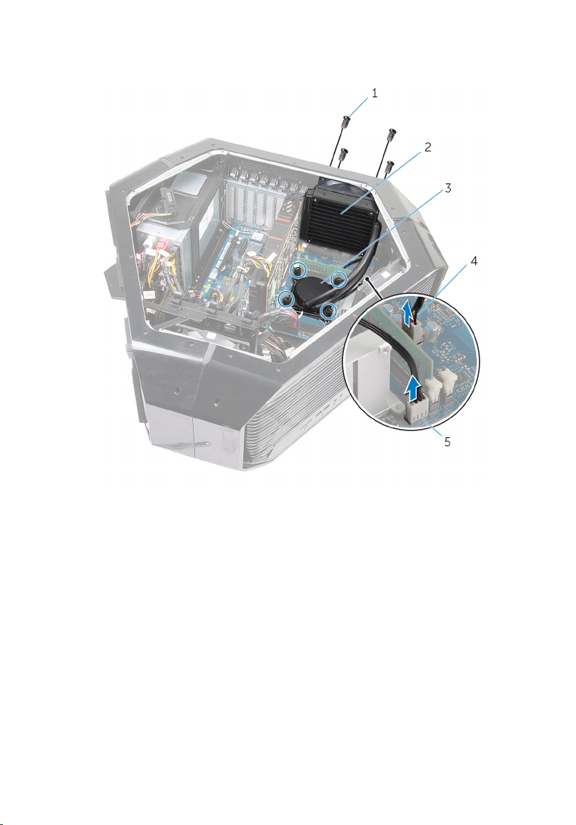
5 Remove the screws that secure the processor liquid-cooling assembly fan
to the chassis.
1 screws (4) 2 processor liquid-cooling
assembly fan
3 processor liquid-cooling
assembly pump
5 processor liquid-cooling
assembly fan cable
4 processor liquid-cooling
assembly pump cable
93
Page 94

6 Slide and lift the processor liquid-cooling assembly out of the chassis.
94
1 processor liquid-cooling
assembly
2 processor liquid-cooling
assembly pump
Page 95

Replacing the Processor Cooling Assembly
WARNING: Before working inside your computer, read the
safety information that shipped with your computer and
follow the steps in
After working inside your computer, follow the instructions
in After Working Inside Your Computer. For more safety best
practices, see the Regulatory Compliance home page at
dell.com/regulatory_compliance.
Procedure
CAUTION: Incorrect alignment of the processor liquidcooling assembly can damage the system board and
processor.
1 Align the screw holes on the processor liquid-cooling assembly with the
screw holes on the chassis.
2 Replace the screws that secure the processor liquid-cooling assembly to
the chassis.
NOTE: The original thermal grease can be reused if the original
processor and processor liquid-cooling are reinstalled together. If
either the processor or the processor liquid-cooling is replaced, use
the thermal grease provided in the kit to ensure that thermal
conductivity is achieved.
3 Apply thermal grease between the processor liquid-cooling assembly and
the processor.
4 In sequential order as indicated on the processor cooling-assembly,
tighten the captive screws that secure the processor liquid-cooling
assembly to the system board.
5 Connect the processor liquid-cooling assembly fan and the processor
liquid-cooling assembly pump-fan cable to the connectors on the system
board.
Before Working Inside Your Computer.
95
Page 96

Post-requisites
1 Replace both the left and right side-panels. See “Removing the Side
Panels”.
2 Replace the stability foot.
96
Page 97

Removing the Processor
WARNING: Before working inside your computer, read the
safety information that shipped with your computer and
follow the steps in
After working inside your computer, follow the instructions
in After Working Inside Your Computer. For more safety best
practices, see the Regulatory Compliance home page at
dell.com/regulatory_compliance.
Prerequisites
1 Remove the stability foot.
2 Remove both the left and right side-panels. See “Removing the Side
Panels”.
3 Remove the processor liquid-cooling assembly fan.
Procedure
WARNING: The processor might still be hot after the
computer is shut down. Allow the processor to cool down
before removing it.
1 Lay the computer on the left side.
2 Press down and push the left-release lever away from the processor to
release it from the securing tab.
3 Press down and push the right-release lever away from the processor to
release it from the securing tab.
4 Extend the right-release lever completely to open the processor cover.
Before Working Inside Your Computer.
CAUTION: When removing the processor, do not touch
any of the pins inside the socket or allow any objects to
fall on the pins in the socket.
97
Page 98

5 Open the processor cover and gently lift the processor from the processor
socket.
98
1 left release-lever 2 right release-lever
3 processor cover 4 processor
Page 99

Replacing the Processor
WARNING: Before working inside your computer, read the
safety information that shipped with your computer and
follow the steps in
After working inside your computer, follow the instructions
in After Working Inside Your Computer. For more safety best
practices, see the Regulatory Compliance home page at
dell.com/regulatory_compliance.
CAUTION: If either the processor or the heat sink is replaced,
use the thermal grease provided in the kit to make sure that
thermal conductivity is achieved.
Procedure
1 Ensure that the right-release lever is fully extended in the open position.
CAUTION: You must position the processor correctly in
the processor socket to avoid damage to the processor.
2 Align the pin-1 corner of the processor with the pin-1 corner of the
processor socket, and then place the processor in the processor socket.
NOTE: The pin-1 corner of the processor has a triangle that aligns
with the triangle on the pin-1 corner on the processor socket. When
the processor is properly seated, all four corners are aligned at the
same height. If one or more corners of the processor are higher than
the others, the processor is not seated properly.
3 When the processor is fully seated in the socket, close the processor cover.
4 Press down and push the left-release lever. Place it under the tab on the
processor cover.
Before Working Inside Your Computer.
99
Page 100

5 Press down and push the right-release lever. Place it under the tab on the
processor cover.
1 processor 2 processor pin-1 connector
3 processor cover 4 left release-lever
5 right release-lever
Post-requisites
1 Replace the processor liquid-cooling assembly fan.
2 Replace both the left and right side-panels. See “Replacing the Side
Panels”.
3 Replace the stability foot.
100
 Loading...