

Dell Alienware 18 Owners Manual

Alienware 18
Owner’s Manual
Computer model: Alienware 18
Regulatory model: P19E
Regulatory type: P19E001

Notes, Cautions, and Warnings
NOTE: A NOTE indicates important information that helps you make
better use of your computer.
CAUTION: A CAUTION indicates potential damage to
hardware or loss of data if instructions are not followed.
WARNING: A WARNING indicates a potential for property damage,
personal injury, or death.
____________________
Information in this document is subject to change without notice.
© 2013 Dell Inc. All rights reserved.
Reproduction of these materials in any manner whatsoever without the written permission
of Dell Inc. is strictly forbidden.
Trademarks used in this text: Alienware™ and the AlienHead logo are trademarks or
registered trademarks of Alienware Corporation; Dell™ is a trademark of Dell Inc.;
Microsoft
registered trademarks of Microsoft corporation in the United States and/or other countries;
Bluetooth
license.
Other trademarks and trade names may be used in this document to refer to either the
entities claiming the marks and names or their product s. Dell Inc. disclaims any proprietary
interest in trademarks and trade names other than its own.
2013 - 07 Rev. A00
®
, Windows®, and the Windows start button logo are either trademarks or
®
is a re gi st er ed tr a de ma rk ow ne d b y Bl ue to ot h S IG , In c. an d i s u se d by De ll un de r

Contents
Before You Begin . . . . . . . . . . . . . . . . . . . . . . . . . . . . . 11
Turn Off Your Computer and Connected Devices . . . . . . 11
Safety Instructions . . . . . . . . . . . . . . . . . . . . . . . . 12
Recommended Tools . . . . . . . . . . . . . . . . . . . . . . . 12
After Working Inside Your Computer . . . . . . . . . . . . . . . . 13
Removing the Base Cover
Procedure . . . . . . . . . . . . . . . . . . . . . . . . . . . . . . 14
Replacing the Base Cover . . . . . . . . . . . . . . . . . . . . . . . . 15
Procedure . . . . . . . . . . . . . . . . . . . . . . . . . . . . . . 15
Postrequisites . . . . . . . . . . . . . . . . . . . . . . . . . . . 15
Removing the Battery Pack . . . . . . . . . . . . . . . . . . . . . . 16
Procedure . . . . . . . . . . . . . . . . . . . . . . . . . . . . . . 16
Replacing the Battery Pack . . . . . . . . . . . . . . . . . . . . . . . 17
Procedure . . . . . . . . . . . . . . . . . . . . . . . . . . . . . . 17
Postrequisites . . . . . . . . . . . . . . . . . . . . . . . . . . . 17
Removing the Memory Module(s) . . . . . . . . . . . . . . . . . . 18
Prerequisites . . . . . . . . . . . . . . . . . . . . . . . . . . . . 18
Procedure . . . . . . . . . . . . . . . . . . . . . . . . . . . . . . 19
Replacing the Memory Module(s) . . . . . . . . . . . . . . . . . 20
Procedure . . . . . . . . . . . . . . . . . . . . . . . . . . . . . . 20
Postrequisites . . . . . . . . . . . . . . . . . . . . . . . . . . . 21
Removing the Optical Drive . . . . . . . . . . . . . . . . . . . . . 22
Prerequisites . . . . . . . . . . . . . . . . . . . . . . . . . . . . 22
. . . . . . . . . . . . . . . . . . . . . . . . 14
Replacing the Optical Drive . . . . . . . . . . . . . . . . . . . . . . 24
Procedure . . . . . . . . . . . . . . . . . . . . . . . . . . . . . . 24
Postrequisites . . . . . . . . . . . . . . . . . . . . . . . . . . . 24
Contents | 3

Removing the Hard Drive(s) . . . . . . . . . . . . . . . . . . . . . 25
Prerequisites . . . . . . . . . . . . . . . . . . . . . . . . . . . . 25
Procedure . . . . . . . . . . . . . . . . . . . . . . . . . . . . . . 26
Replacing the Hard Drive(s) . . . . . . . . . . . . . . . . . . . . . 28
Procedure . . . . . . . . . . . . . . . . . . . . . . . . . . . . . . 28
Postrequisites . . . . . . . . . . . . . . . . . . . . . . . . . . . 28
Removing the Fans Cover . . . . . . . . . . . . . . . . . . . . . . . 29
Prerequisites . . . . . . . . . . . . . . . . . . . . . . . . . . . . 29
Procedure . . . . . . . . . . . . . . . . . . . . . . . . . . . . . . 29
Replacing the Fans Cover . . . . . . . . . . . . . . . . . . . . . . . 30
Procedure . . . . . . . . . . . . . . . . . . . . . . . . . . . . . . 30
Postrequisites . . . . . . . . . . . . . . . . . . . . . . . . . . . 30
Removing the Video-Card Heat-Sink Fan(s) . . . . . . . . . . . . 31
Prerequisites . . . . . . . . . . . . . . . . . . . . . . . . . . . . 31
Procedure . . . . . . . . . . . . . . . . . . . . . . . . . . . . . . 31
Replacing the Video-Card Heat-Sink Fan(s) . . . . . . . . . . . 33
Procedure . . . . . . . . . . . . . . . . . . . . . . . . . . . . . . 33
Postrequisites . . . . . . . . . . . . . . . . . . . . . . . . . . . 33
Removing the Processor Heat-Sink Fan . . . . . . . . . . . . . 34
Prerequisites . . . . . . . . . . . . . . . . . . . . . . . . . . . . 34
Procedure . . . . . . . . . . . . . . . . . . . . . . . . . . . . . . 34
Replacing the Processor Heat-Sink Fan . . . . . . . . . . . . . 35
Procedure . . . . . . . . . . . . . . . . . . . . . . . . . . . . . . 35
Postrequisites . . . . . . . . . . . . . . . . . . . . . . . . . . . 35
Removing the Coin-Cell Battery . . . . . . . . . . . . . . . . . . . 36
Prerequisites . . . . . . . . . . . . . . . . . . . . . . . . . . . . 36
Procedure . . . . . . . . . . . . . . . . . . . . . . . . . . . . . . 37
Replacing the Coin-Cell Battery . . . . . . . . . . . . . . . . . . . 38
Procedure . . . . . . . . . . . . . . . . . . . . . . . . . . . . . . 38
Postrequisites . . . . . . . . . . . . . . . . . . . . . . . . . . . 38
4 | Contents

Removing the Palm Rest
. . . . . . . . . . . . . . . . . . . . . . . 39
Prerequisites . . . . . . . . . . . . . . . . . . . . . . . . . . . . 39
Procedure . . . . . . . . . . . . . . . . . . . . . . . . . . . . . . 40
Replacing the Palm Rest . . . . . . . . . . . . . . . . . . . . . . . 42
Procedure . . . . . . . . . . . . . . . . . . . . . . . . . . . . . . 42
Postrequisites . . . . . . . . . . . . . . . . . . . . . . . . . . . 42
Removing the mSATA Card . . . . . . . . . . . . . . . . . . . . . . 43
Prerequisites . . . . . . . . . . . . . . . . . . . . . . . . . . . . 43
Procedure . . . . . . . . . . . . . . . . . . . . . . . . . . . . . . 43
Replacing the mSATA Card . . . . . . . . . . . . . . . . . . . . . . 44
Procedure . . . . . . . . . . . . . . . . . . . . . . . . . . . . . . 44
Postrequisites . . . . . . . . . . . . . . . . . . . . . . . . . . . 44
Removing the Power-Button Board . . . . . . . . . . . . . . . . 45
Prerequisites . . . . . . . . . . . . . . . . . . . . . . . . . . . . 45
Procedure . . . . . . . . . . . . . . . . . . . . . . . . . . . . . . 45
Replacing the Power-Button Board . . . . . . . . . . . . . . . . 46
Procedure . . . . . . . . . . . . . . . . . . . . . . . . . . . . . . 46
Postrequisites . . . . . . . . . . . . . . . . . . . . . . . . . . . 46
Removing the Status-Light Board . . . . . . . . . . . . . . . . . 47
Prerequisites . . . . . . . . . . . . . . . . . . . . . . . . . . . . 47
Procedure . . . . . . . . . . . . . . . . . . . . . . . . . . . . . . 48
Replacing the Status-Light Board . . . . . . . . . . . . . . . . . 49
Procedure . . . . . . . . . . . . . . . . . . . . . . . . . . . . . . 49
Postrequisites . . . . . . . . . . . . . . . . . . . . . . . . . . . 49
Removing the Keyboard . . . . . . . . . . . . . . . . . . . . . . . . 50
Prerequisites . . . . . . . . . . . . . . . . . . . . . . . . . . . . 50
Procedure . . . . . . . . . . . . . . . . . . . . . . . . . . . . . . 51
Replacing the Keyboard . . . . . . . . . . . . . . . . . . . . . . . . 53
Procedure . . . . . . . . . . . . . . . . . . . . . . . . . . . . . . 53
Postrequisites . . . . . . . . . . . . . . . . . . . . . . . . . . . 53
Contents | 5

Removing the Macro Keyboard . . . . . . . . . . . . . . . . . . . 54
Prerequisites . . . . . . . . . . . . . . . . . . . . . . . . . . . . 54
Procedure . . . . . . . . . . . . . . . . . . . . . . . . . . . . . . 54
Replacing the Macro Keyboard . . . . . . . . . . . . . . . . . . . 55
Procedure . . . . . . . . . . . . . . . . . . . . . . . . . . . . . . 55
Postrequisites . . . . . . . . . . . . . . . . . . . . . . . . . . . 55
Removing the Display Assembly . . . . . . . . . . . . . . . . . . 56
Prerequisites . . . . . . . . . . . . . . . . . . . . . . . . . . . . 56
Procedure . . . . . . . . . . . . . . . . . . . . . . . . . . . . . . 56
Replacing the Display Assembly . . . . . . . . . . . . . . . . . . 60
Procedure . . . . . . . . . . . . . . . . . . . . . . . . . . . . . . 60
Postrequisites . . . . . . . . . . . . . . . . . . . . . . . . . . . 60
Removing the Camera Module . . . . . . . . . . . . . . . . . . . . . 61
Prerequisites . . . . . . . . . . . . . . . . . . . . . . . . . . . . 61
Procedure . . . . . . . . . . . . . . . . . . . . . . . . . . . . . . 62
Replacing the Camera Module . . . . . . . . . . . . . . . . . . . . 63
Procedure . . . . . . . . . . . . . . . . . . . . . . . . . . . . . . 63
Postrequisites . . . . . . . . . . . . . . . . . . . . . . . . . . . 63
Removing the Display Bezel . . . . . . . . . . . . . . . . . . . . . 64
Prerequisites . . . . . . . . . . . . . . . . . . . . . . . . . . . . 64
Procedure . . . . . . . . . . . . . . . . . . . . . . . . . . . . . . 64
Replacing the Display Bezel . . . . . . . . . . . . . . . . . . . . . 65
Procedure . . . . . . . . . . . . . . . . . . . . . . . . . . . . . . 65
Postrequisites . . . . . . . . . . . . . . . . . . . . . . . . . . . 65
Removing the Display Hinges . . . . . . . . . . . . . . . . . . . . 66
Prerequisites . . . . . . . . . . . . . . . . . . . . . . . . . . . . 66
Procedure . . . . . . . . . . . . . . . . . . . . . . . . . . . . . . 66
Replacing the Display Hinges . . . . . . . . . . . . . . . . . . . . 67
Procedure . . . . . . . . . . . . . . . . . . . . . . . . . . . . . . 67
Postrequisites . . . . . . . . . . . . . . . . . . . . . . . . . . . 67
6 | Contents

Removing the Display Panel
. . . . . . . . . . . . . . . . . . . . . 68
Prerequisites . . . . . . . . . . . . . . . . . . . . . . . . . . . . 68
Procedure . . . . . . . . . . . . . . . . . . . . . . . . . . . . . . 69
Replacing the Display Panel . . . . . . . . . . . . . . . . . . . . . 72
Procedure . . . . . . . . . . . . . . . . . . . . . . . . . . . . . . 72
Postrequisites . . . . . . . . . . . . . . . . . . . . . . . . . . . 72
Removing the Logo Board . . . . . . . . . . . . . . . . . . . . . . 73
Prerequisites . . . . . . . . . . . . . . . . . . . . . . . . . . . . 73
Procedure . . . . . . . . . . . . . . . . . . . . . . . . . . . . . . 74
Replacing the Logo Board . . . . . . . . . . . . . . . . . . . . . . . 75
Procedure . . . . . . . . . . . . . . . . . . . . . . . . . . . . . . 75
Postrequisites . . . . . . . . . . . . . . . . . . . . . . . . . . . 75
Removing the Display-Light Boards . . . . . . . . . . . . . . . . 76
Prerequisites . . . . . . . . . . . . . . . . . . . . . . . . . . . . 76
Procedure . . . . . . . . . . . . . . . . . . . . . . . . . . . . . . 77
Replacing the Display-Light Boards . . . . . . . . . . . . . . . . 78
Procedure . . . . . . . . . . . . . . . . . . . . . . . . . . . . . . 78
Postrequisites . . . . . . . . . . . . . . . . . . . . . . . . . . . 78
Removing the Speakers . . . . . . . . . . . . . . . . . . . . . . . . 79
Prerequisites . . . . . . . . . . . . . . . . . . . . . . . . . . . . 79
Procedure . . . . . . . . . . . . . . . . . . . . . . . . . . . . . . 80
Replacing the Speakers . . . . . . . . . . . . . . . . . . . . . . . . . 81
Procedure . . . . . . . . . . . . . . . . . . . . . . . . . . . . . . 81
Postrequisites . . . . . . . . . . . . . . . . . . . . . . . . . . . 81
Removing the Subwoofer . . . . . . . . . . . . . . . . . . . . . . . 82
Prerequisites . . . . . . . . . . . . . . . . . . . . . . . . . . . . 82
Procedure . . . . . . . . . . . . . . . . . . . . . . . . . . . . . . 83
Replacing the Subwoofer . . . . . . . . . . . . . . . . . . . . . . . 84
Procedure . . . . . . . . . . . . . . . . . . . . . . . . . . . . . . 84
Postrequisites . . . . . . . . . . . . . . . . . . . . . . . . . . . 84
Contents | 7

Removing the Sound Board . . . . . . . . . . . . . . . . . . . . . 85
Prerequisites . . . . . . . . . . . . . . . . . . . . . . . . . . . . 85
Procedure . . . . . . . . . . . . . . . . . . . . . . . . . . . . . . 86
Replacing the Sound Board . . . . . . . . . . . . . . . . . . . . . . 87
Procedure . . . . . . . . . . . . . . . . . . . . . . . . . . . . . . 87
Postrequisites . . . . . . . . . . . . . . . . . . . . . . . . . . . 87
Removing the Video-Card Heat-Sink(s) . . . . . . . . . . . . . 88
Prerequisites . . . . . . . . . . . . . . . . . . . . . . . . . . . . 88
Procedure . . . . . . . . . . . . . . . . . . . . . . . . . . . . . . 88
Replacing the Video-Card Heat-Sink(s) . . . . . . . . . . . . . . 90
Procedure . . . . . . . . . . . . . . . . . . . . . . . . . . . . . . 90
Postrequisites . . . . . . . . . . . . . . . . . . . . . . . . . . . 90
Removing the Video Card(s) . . . . . . . . . . . . . . . . . . . . . . 91
Prerequisites . . . . . . . . . . . . . . . . . . . . . . . . . . . . 91
Procedure . . . . . . . . . . . . . . . . . . . . . . . . . . . . . . 91
Replacing the Video Card(s) . . . . . . . . . . . . . . . . . . . . . 93
Procedure . . . . . . . . . . . . . . . . . . . . . . . . . . . . . . 93
Postrequisites . . . . . . . . . . . . . . . . . . . . . . . . . . . 93
Removing the Processor Heat-Sink . . . . . . . . . . . . . . . . 94
Prerequisites . . . . . . . . . . . . . . . . . . . . . . . . . . . . 94
Procedure . . . . . . . . . . . . . . . . . . . . . . . . . . . . . . 94
Replacing the Processor Heat-Sink . . . . . . . . . . . . . . . . 95
Procedure . . . . . . . . . . . . . . . . . . . . . . . . . . . . . . 95
Postrequisites . . . . . . . . . . . . . . . . . . . . . . . . . . . 95
Removing the Processor Module . . . . . . . . . . . . . . . . . . 96
Prerequisites . . . . . . . . . . . . . . . . . . . . . . . . . . . . 96
Procedure . . . . . . . . . . . . . . . . . . . . . . . . . . . . . . 97
Replacing the Processor Module . . . . . . . . . . . . . . . . . . 98
Procedure . . . . . . . . . . . . . . . . . . . . . . . . . . . . . . 98
Postrequisites . . . . . . . . . . . . . . . . . . . . . . . . . . . 99
8 | Contents

Removing the System Board
. . . . . . . . . . . . . . . . . . . . . 100
Prerequisites . . . . . . . . . . . . . . . . . . . . . . . . . . . 100
Procedure . . . . . . . . . . . . . . . . . . . . . . . . . . . . . . 101
Replacing the System Board . . . . . . . . . . . . . . . . . . . . . 103
Procedure . . . . . . . . . . . . . . . . . . . . . . . . . . . . . 103
Postrequisites . . . . . . . . . . . . . . . . . . . . . . . . . . 103
Entering the Service Tag in the BIOS . . . . . . . . . . . . 104
Removing the Wireless Mini-Card . . . . . . . . . . . . . . . . . 105
Prerequisites . . . . . . . . . . . . . . . . . . . . . . . . . . . 105
Procedure . . . . . . . . . . . . . . . . . . . . . . . . . . . . . 106
Replacing the Wireless Mini-Card . . . . . . . . . . . . . . . . . 107
Procedure . . . . . . . . . . . . . . . . . . . . . . . . . . . . . . 107
Postrequisites . . . . . . . . . . . . . . . . . . . . . . . . . . 108
System Setup . . . . . . . . . . . . . . . . . . . . . . . . . . . . . . . 109
Overview . . . . . . . . . . . . . . . . . . . . . . . . . . . . . . 109
Entering System Setup. . . . . . . . . . . . . . . . . . . . . 109
System Setup Screens . . . . . . . . . . . . . . . . . . . . . . 110
System Setup Options . . . . . . . . . . . . . . . . . . . . . . 110
Boot Sequence . . . . . . . . . . . . . . . . . . . . . . . . . . . 117
Flashing the BIOS . . . . . . . . . . . . . . . . . . . . . . . . . . . . 119
Contents | 9

10 | Contents

Before You Begin
Turn Off Your Computer and Connected Devices
CAUTION: To avoid losing data, save and close all open files and exit
all open programs before you turn off your computer.
1 Save and close all open files and exit all open programs.
2 Follow the instructions to shut down your computer based on the operating system
installed on your computer.
• Windows 8:
Move your mouse pointer to the upper-right or lower-right corner of the screen to open
the Charms sidebar, and then click
Microsoft Windows shuts down and then the computer turns off.
• Windows 7:
Click
Start and click Shut down.
NOTE: If you are using a different operating system, see the documentation
of your operating system for shut-down instructions.
3 Disconnect your computer and all attached devices from their electrical outlets.
4 Disconnect all telephone cables, network cables, and attached devices from your
computer.
5 After the computer is unplugged, press and hold the power button for about 5
seconds to ground the system board.
Settings→ Power→ Shut Down.
Before You Begin | 11

Safety Instructions
Use the following safety guidelines to protect your computer from potential damage and
ensure your personal safety.
WARNING: Disconnect all power sources before opening the
computer cover or panels. After you finish working inside the
computer, replace all covers, panels, and screws before connecting to
the power source.
WARNING: Before working inside your computer, read the safety
information that shipped with your computer. For additional safety
best practices information, see the Regulatory Compliance
Homepage at dell.com/regulatory_compliance.
CAUTION: To avoid damaging the computer, ensure that the work
surface is flat and clean.
CAUTION: To avoid damaging the components and cards, handle
them by their edges and avoid touching pins and contacts.
CAUTION: Only a certified service technician is authorized to remove
the computer cover and access any of the components inside the
computer. See the safety instructions for complete information
about safety precautions, working inside your computer, and
protecting against electrostatic discharge.
CAUTION: Before touching anything inside your computer, ground
yourself by touching an unpainted metal surface, such as the metal
at the back of the computer. While you work, periodically touch an
unpainted metal surface to dissipate static electricity, which could
harm internal components.
CAUTION: When you disconnect a cable, pull on its connector or on
its pull-tab, not on the cable itself. Some cables have connectors with
locking tabs or thumb-screws that you must disengage before
disconnecting the cable. When disconnecting cables, keep them
evenly aligned to avoid bending any connector pins. When
connecting cables, ensure that the connectors and ports are
correctly oriented and aligned.
CAUTION: To disconnect a network cable, first unplug the cable from
your computer and then unplug the cable from the network device.
Recommended Tools
The procedures in this document may require the following tools:
• Phillips screwdriver
• Plastic scribe
• Small flat-blade screwdriver
12 | Before You Begin

After Working Inside Your Computer
After you complete the replacement procedures, ensure the following:
• Replace all screws and ensure that no stray screws remain inside your computer
• Connect any external devices, cables, cards, and any other part(s) you removed
before working on your computer
• Connect your computer and all attached devices to their electrical outlets
CAUTION: Before turning on your computer, replace all screws and
ensure that no stray screws remain inside the computer. Failure to do
so may damage your computer.
After Working Inside Your Computer | 13
Removing the Base Cover
1
2
WARNING: Before working inside your computer, read the safety
information that shipped with your computer and follow the steps in
"Before You Begin" on page 11. For additional safety best practices
information, see the Regulatory Compliance Homepage at
dell.com/regulatory_compliance.
Procedure
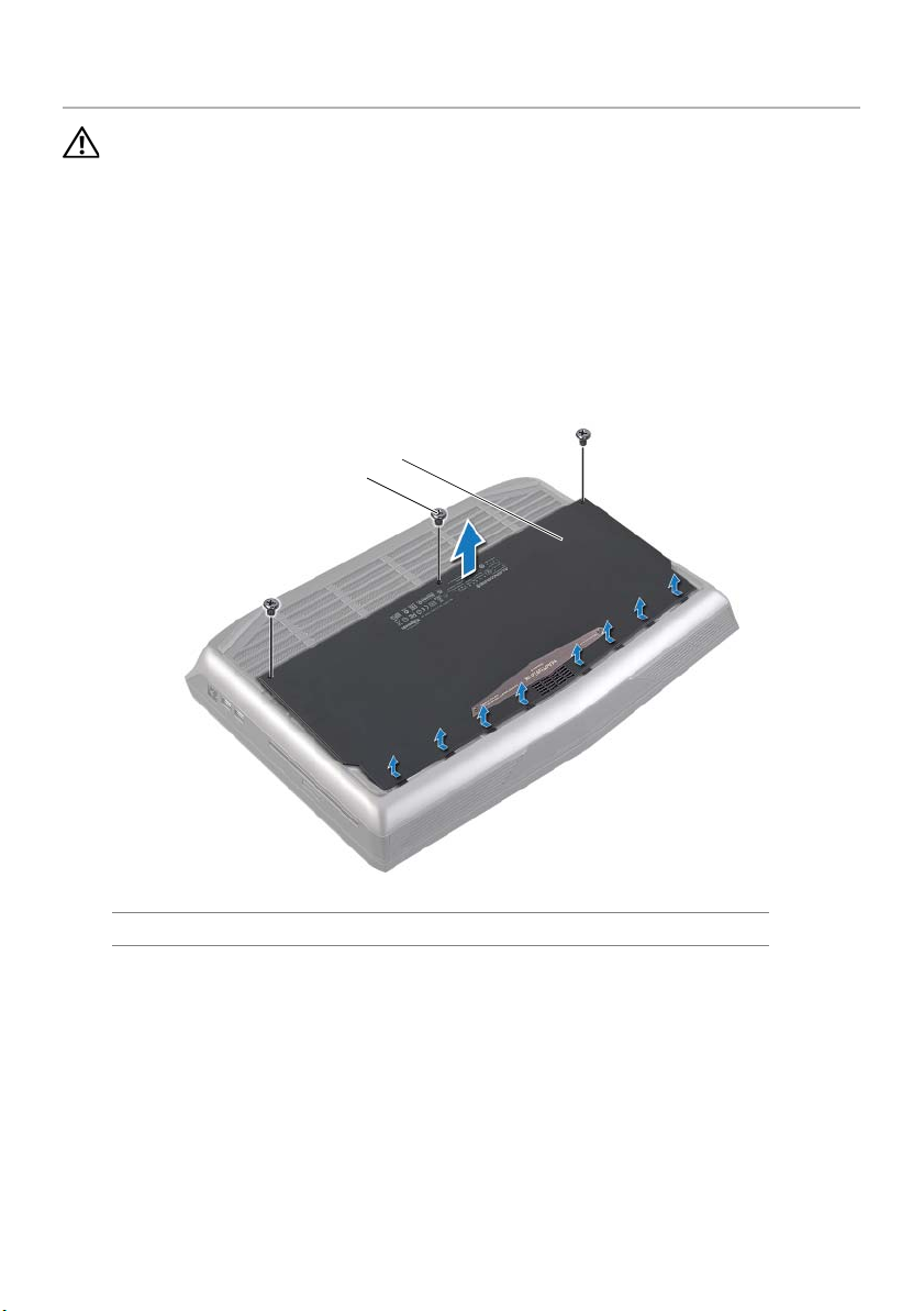
1 Remove the screws that secure the base cover to the computer base.
1 screws (3) 2 base cover
2 Slide the base cover towards the rear of the computer and lift it off the computer
base.
14 | Removing the Base Cover

Replacing the Base Cover
WARNING: Before working inside your computer, read the safety
information that shipped with your computer and follow the steps in
"Before You Begin" on page 11. For additional safety best practices
information, see the Regulatory Compliance Homepage at
dell.com/regulatory_compliance.
Procedure
1 Align the tabs on the base cover with the slots on the computer base and slide the
base cover into place.
2 Replace the screws that secure the base cover to the computer base.
Postrequisites
Follow the instructions in "After Working Inside Your Computer" on page 13.
Replacing the Base Cover | 15
Removing the Battery Pack
1
3
2
WARNING: Before working inside your computer, read the safety
information that shipped with your computer and follow the steps in
"Before You Begin" on page 11. For additional safety best practices
information, see the Regulatory Compliance Homepage at
dell.com/regulatory_compliance.
Prerequisites
Remove the base cover. See "Removing the Base Cover" on page 14.
Procedure
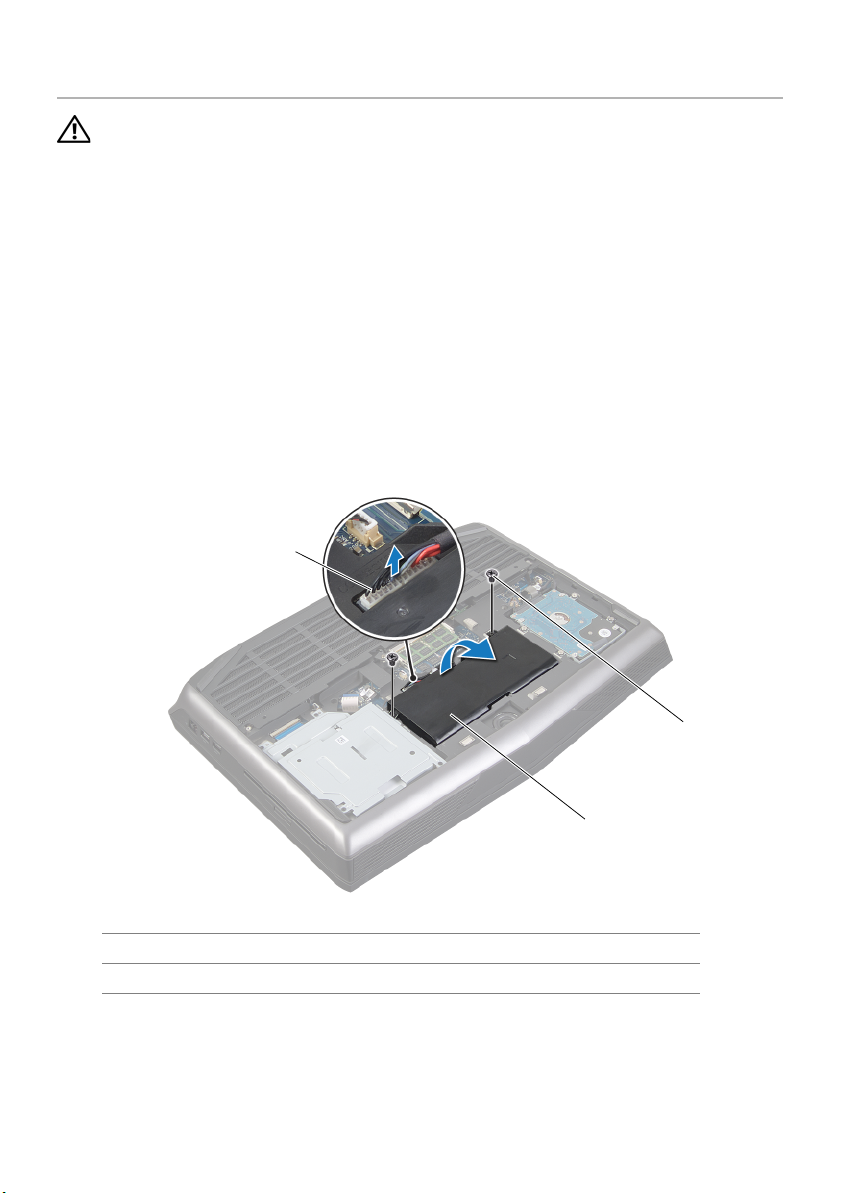
1 Remove the screws that secure the battery to the computer base.
2 Disconnect the battery cable from its connector on the system board.
1 battery cable 2 screws (2)
3 battery pack
3 Lift the battery pack away from the computer base.
16 | Removing the Battery Pack

Replacing the Battery Pack
WARNING: Before working inside your computer, read the safety
information that shipped with your computer and follow the steps in
"Before You Begin" on page 11. For additional safety best practices
information, see the Regulatory Compliance Homepage at
dell.com/regulatory_compliance.
CAUTION: To avoid damage to the computer, use only the battery
designed for this particular Alienware computer.
Procedure
1 Align the tabs on the battery with the slots on the computer base and place the
battery on the computer base.
2 Connect the battery cable to its connector on the system board.
3 Replace the screws that secure the battery to the computer base.
Postrequisites
1 Replace the base cover. See "Replacing the Base Cover" on page 15.
2 Follow the instructions in "After Working Inside Your Computer" on page 13.
Replacing the Battery Pack | 17

Removing the Memory Module(s)
WARNING: Before working inside your computer, read the safety
information that shipped with your computer and follow the steps in
"Before You Begin" on page 11. For additional safety best practices
information, see the Regulatory Compliance Homepage at
dell.com/regulatory_compliance.
NOTE: Your computer supports up to four memory module connectors. You can
access connectors DIMM3 and DIMM4 by removing the base cover at the bottom of
your computer. You can access connectors DIMM1 and DIMM2 by removing the
keyboard.
Prerequisites
1 Remove the base cover. See "Removing the Base Cover" on page 7.
2 Remove the battery. See "Removing the Battery Pack" on page 16.
18 | Removing the Memory Module(s)
Procedure
3
2
1
1 To remove memory module(s) from connectors DIMM3 and DIMM4, go to step 3.
2 To remove memory module(s) from connectors DIMM1 and DIMM2:
Remove the palm rest. See "Removing the Palm Rest" on page 39.
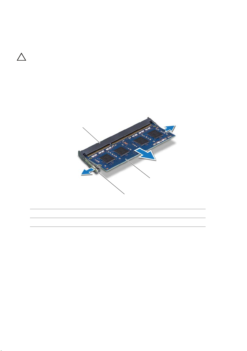
CAUTION: To prevent damage to the memory-module connector, do
not use tools to spread the memory module securing clips.
3 Using your fingertips, spread apart the securing clips on each end of the
memory-module connector until the memory module pops up.
4 Remove the memory module from the memory-module connector.
1 memory-module connector 2 securing clips (2)
3 memory module
Removing the Memory Module(s) | 19
Replacing the Memory Module(s)
3
1
2
WARNING: Before working inside your computer, read the safety
information that shipped with your computer and follow the steps in
"Before You Begin" on page 11. For additional safety best practices
information, see the Regulatory Compliance Homepage at
dell.com/regulatory_compliance.
NOTE: Your computer supports up to four memory module connectors. You can
access connectors DIMM3 and DIMM4 by removing the base cover at the bottom of
your computer. You can access connectors DIMM1 and DIMM2 by removing the
palmrest.
Procedure
NOTE: If you need to install memory modules in two connectors, install a memory
module in the lower connector before you install a memory module in the upper
connector.
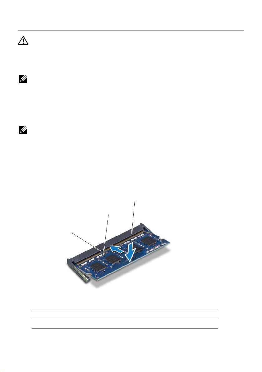
1 Align the notch on the memory module with the tab on the memory-module
connector.
2 Slide the memory module firmly into the connector at a 45-degree angle and press
the memory module down until it clicks into place. If you do not hear the click,
remove the memory module and reinstall it.
1tab 2notch
3 memory-module connector
20 | Replacing the Memory Module(s)

3 If you have replaced memory module(s) in connectors DIMM3 and DIMM4, go to
Postrequisites.
4 If you have replaced memory module(s) in connectors DIMM1 and DIMM2:
Replace the palm rest. See "Replacing the Palm Rest" on page 42.
Postrequisites
1 Replace the battery pack. See "Replacing the Battery Pack" on page 17.
2 Replace the base cover. See "Replacing the Base Cover" on page 15.
3 Follow the instructions in "After Working Inside Your Computer" on page 13.
Replacing the Memory Module(s) | 21
Removing the Optical Drive
3
2
1
WARNING: Before working inside your computer, read the safety
information that shipped with your computer and follow the steps in
"Before You Begin" on page 11. For additional safety best practices
information, see the Regulatory Compliance Homepage at
dell.com/regulatory_compliance.
Prerequisites
1 Remove the base cover. See "Removing the Base Cover" on page 14.
2 Remove the battery pack. See "Removing the Battery Pack" on page 16.
Procedure
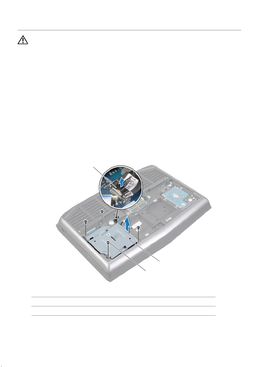
1 Disconnect the optical-drive cable from its connector on the system board.
2 Remove the screws that secure the optical-drive assembly to the computer base.
3 Lift the optical-drive assembly off the computer base.
1 optical-drive cable 2 optical drive
3 screws (4)
22 | Removing the Optical Drive
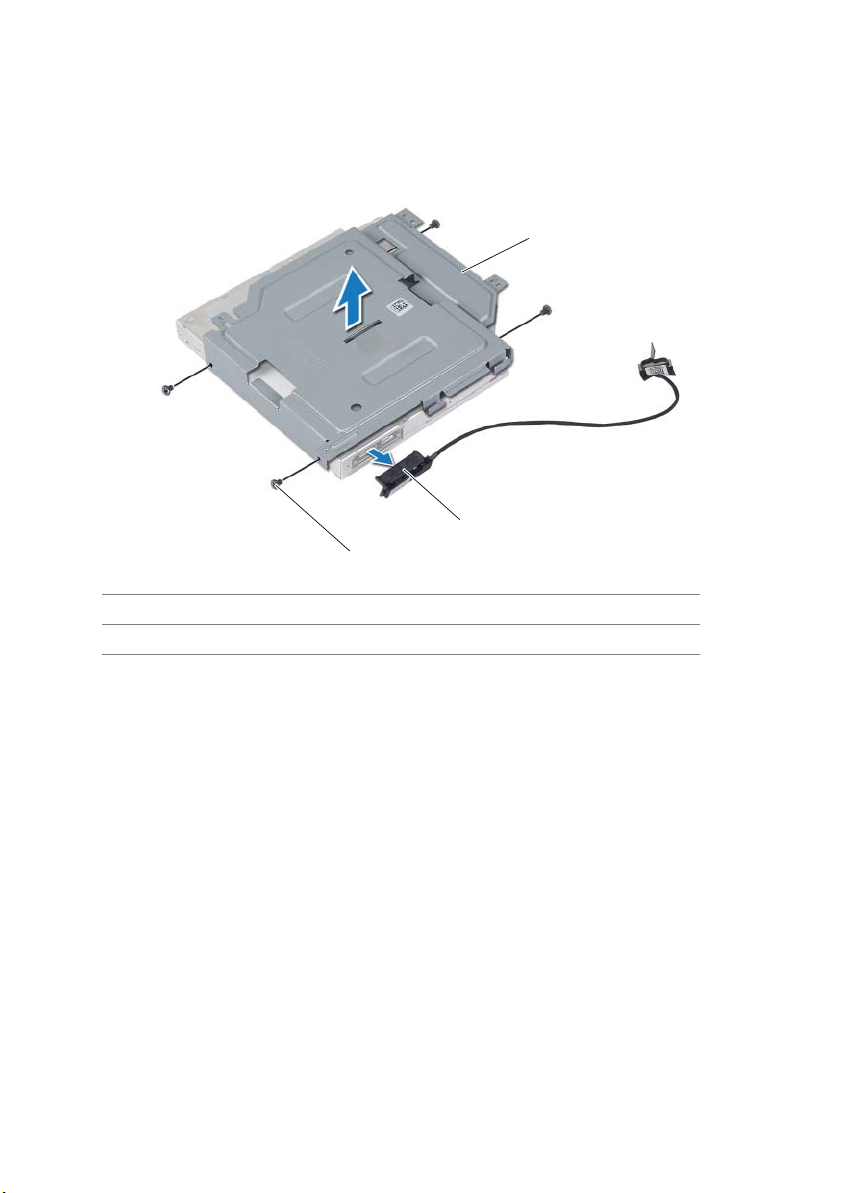
4 Remove the screws that secure the optical-drive bracket to the optical drive.
3
2
1
5 Lift the optical-drive bracket off the optical drive.
1 optical-drive bracket 2 interposer
3 screws (4)
6 Remove the interposer from the optical drive.
Removing the Optical Drive | 23

Replacing the Optical Drive
WARNING: Before working inside your computer, read the safety
information that shipped with your computer and follow the steps in
"Before You Begin" on page 11. For additional safety best practices
information, see the Regulatory Compliance Homepage at
dell.com/regulatory_compliance.
Procedure
1 Connect the interposer to the optical drive.
2 Align the screw holes on the optical-drive bracket with the screw holes on the optical
drive and replace the screws that secure the optical-drive bracket to the optical
drive.
3 Align the slot on the optical drive with the alignment posts on computer base and
place the optical drive in the computer base.
4 Replace the screws that secure the optical drive to the computer base.
5 Connect the optical-drive cable to its connector on the system board.
Postrequisites
1 Replace the battery pack. See "Replacing the Battery Pack" on page 17.
2 Replace the base cover. See "Replacing the Base Cover" on page 15.
3 Follow the instructions in "After Working Inside Your Computer" on page 13.
24 | Replacing the Optical Drive

Removing the Hard Drive(s)
WARNING: Before working inside your computer, read the safety
information that shipped with your computer and follow the steps in
"Before You Begin" on page 11. For additional safety best practices
information, see the Regulatory Compliance Homepage at
dell.com/regulatory_compliance.
CAUTION: To avoid data loss, do not remove the hard drive while the
computer is in Sleep or On state.
CAUTION: Hard drives are extremely fragile. Exercise care when
handling the hard drive.
Prerequisites
1 Remove the base cover. See "Removing the Base Cover" on page 14.
2 Remove the battery pack. See "Removing the Battery Pack" on page 16.
Removing the Hard Drive(s) | 25
Procedure
1
3
2
4
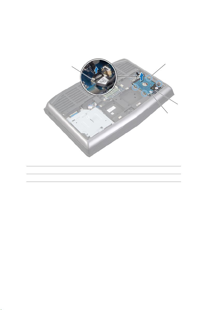
1 Disconnect the hard-drive cable from its connector on the system board.
2 Loosen the captive screws that secure the hard-drive assembly to the computer base.
3 Using the pull-tab, lift the hard-drive assembly out of the computer base.
1 hard-drive cable 2 captive screws (4)
3 pull tab 4 hard drive
26 | Removing the Hard Drive(s)
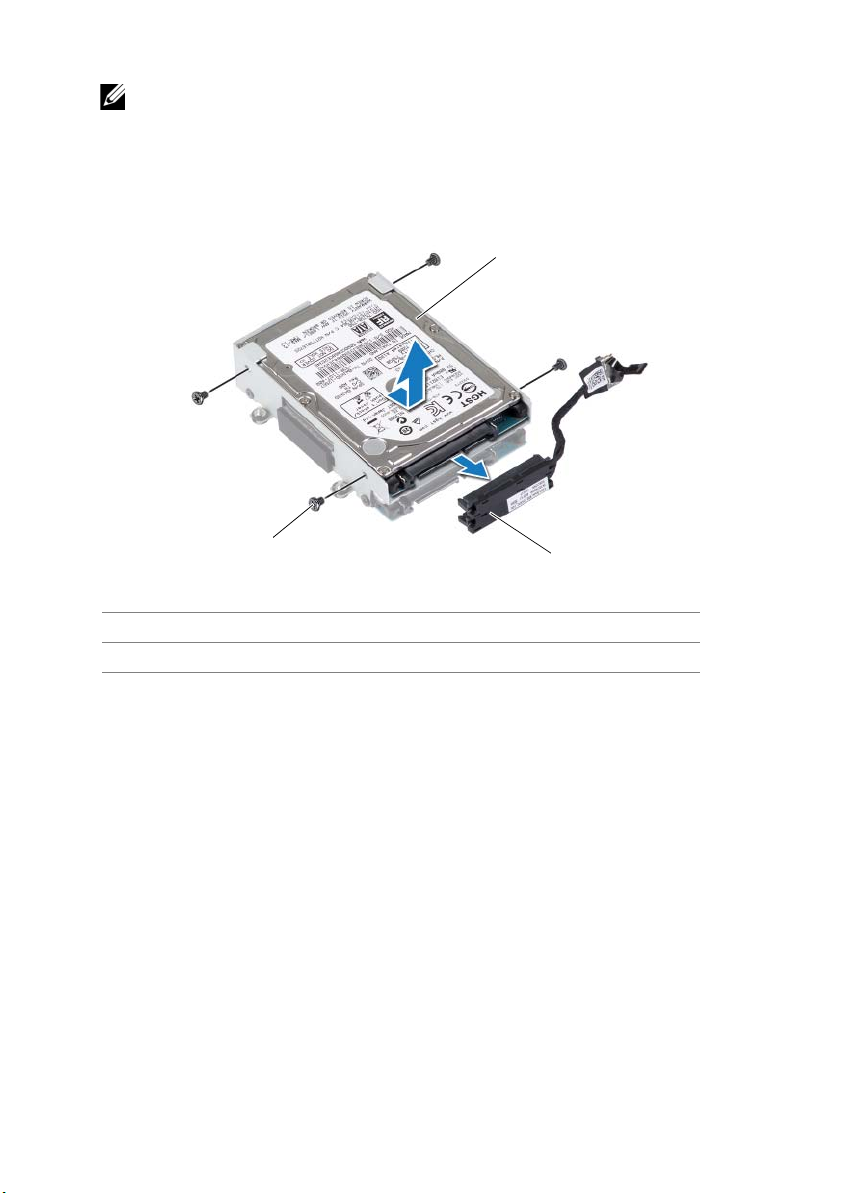
4 Disconnect the interposer from the hard drives.
1
2
3
NOTE: Your computer supports up to three drives.
5 Remove the screws that secure the hard drive(s) to the hard-drive bracket and slide
the hard drive(s) out of the hard-drive bracket.
1 hard drive 2 interposer
3 screws (4)
Removing the Hard Drive(s) | 27

Replacing the Hard Drive(s)
WARNING: Before working inside your computer, read the safety
information that shipped with your computer and follow the steps in
"Before You Begin" on page 11. For additional safety best practices
information, see the Regulatory Compliance Homepage at
dell.com/regulatory_compliance.
NOTE: For drive configurations supported on your computer, see Specifications at
dell.com/support/manuals.
Procedure
1 Place the primary hard drive in the hard-drive bracket.
2 If applicable, slide the secondary hard drive into the hard-drive bracket.
3 Replace the screws that secure the primary hard drive to the hard-drive bracket.
4 If applicable, replace the screws that secure the secondary hard drive to the hard-
drive bracket.
5 Connect the interposer to the hard drives.
6 Place the hard-drive assembly in the computer base.
7 Tighten the captive screws that secure the hard-drive assembly to the computer
base.
8 Connect the hard-drive cable to its connector on the system board.
Postrequisites
1 Replace the battery pack. See "Replacing the Battery Pack" on page 17.
2 Replace the base cover. See "Replacing the Base Cover" on page 15.
3 Follow the instructions in "After Working Inside Your Computer" on page 13.
4 Install the operating system for your computer, if needed.
5 Install the drivers and utilities for your computer, if needed.
28 | Replacing the Hard Drive(s)
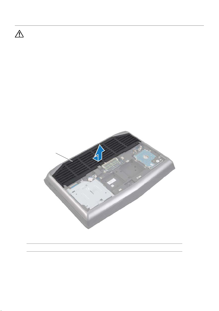
Removing the Fans Cover
1
WARNING: Before working inside your computer, read the safety
information that shipped with your computer and follow the steps in
"Before You Begin" on page 11. For additional safety best practices
information, see the Regulatory Compliance Homepage at
dell.com/regulatory_compliance.
Prerequisites
1 Remove the base cover. See "Removing the Base Cover" on page 14.
2 Remove the battery pack. See "Removing the Battery Pack" on page 16.
Procedure
Slide and lift the fans cover off the computer base.
1fans cover
Removing the Fans Cover | 29

Replacing the Fans Cover
WARNING: Before working inside your computer, read the safety
information that shipped with your computer and follow the steps in
"Before You Begin" on page 11. For additional safety best practices
information, see the Regulatory Compliance Homepage at
dell.com/regulatory_compliance.
Procedure
Align the tabs on the fans cover with the slots on the computer base and slide the fans
cover into place.
Postrequisites
1 Replace the battery pack. See "Replacing the Battery Pack" on page 17.
2 Replace the base cover. See "Replacing the Base Cover" on page 15.
3 Follow the instructions in "After Working Inside Your Computer" on page 13.
30 | Replacing the Fans Cover
 Loading...