


Delfield F18 SERIES Service Manual

F18 SERIES
Service and Installation Manual
Please read this manual completely before attempting to install or operate this equipment! Notify carrier of damage! Inspect all components immediately.
Refrigerated Work Tables, Salad Tables & Freezer Bases
|
|
|
|
INFORMATION |
||
IMPORTANT |
|
|
USE |
|||
|
READ |
BEFORE |
|
|||
|
|
|
INSTRUCTIONS! |
|||
|
SAVE |
THESE |
||||
|
|
|
||||
PLEASE |
|
|
|
|
|
|
|
|
|
|
|
|
|
July 2011
F18 Series Service and Installation Manual
Important Warning And Safety Information
WARNING Read This Manual Thoroughly Before Operating, Installing, Or Performing Maintenance On The Equipment.
WARNING Failure To Follow Instructions In This Manual Can Cause Property Damage, Injury Or Death.
WARNING Do Not Store Or Use Gasoline Or Other Flammable Vapors Or Liquids In The Vicinity Of This Or Any Other Appliance.
WARNING Unless All Cover And Access Panels Are In Place And Properly Secured, Do Not Operate This Equipment.
WARNING Do Not Clean With Water Jet.
CAUTION Observe the following:
•Minimum clearances must be maintained from all walls and combustible
materials.
•Keep the equipment area free and clear of combustible material.
•Adequate clearance for air openings.
•Operate equipment only on the type of electricity indicated on the specification plate.
•Retain this manual for future reference.
2For customer service, call (800) 733-8829, (800) 773-8821, Fax (989) 773-3210, www.delfield.com

F18 Series Service and Installation Manual
Contents |
|
Serial Number Location ........................................................ |
3 |
Receiving & Inspecting......................................................... |
3 |
Specifications.................................................................... |
4-6 |
Installation ............................................................................ |
7 |
Operation .............................................................................. |
8 |
Temperature Settings............................................................ |
9 |
Maintenance.................................................................. |
10-11 |
Wiring Diagrams........................................................... |
12-15 |
Replacement Part Lists................................................. |
16-19 |
Replacement Part Assemblies ...................................... |
20-23 |
Warranties..................................................................... |
24-26 |
Notes .................................................................................. |
27 |
Serial Number Location
The serial number on all self-contained F18 Series refrigerated work tables and freezer bases is located on the electrical specifications tag affixed inside the compressor section next to the pressure control.
On remote refrigerated bases with doors, the tag is inside the unit on the coil side. On remote refrigerated bases with drawers, the tag is affixed to the drawer divider. On remote freezer bases, the tag is located on the inside back of the unit.
Always have the serial number of your unit available when calling for parts or service. A complete list of authorized Delfield parts depots is available at www.delfield.com.
©2011 The Delield Company. All rights reserved. Reproduction without written permission is prohibited. “Delield” is a registered trademark of The Delield Company.
Receiving and Inspecting the Equipment
Even though most equipment is shipped crated, care should be taken during unloading so the equipment is not damaged while being moved into the building.
1.Visually inspect the exterior of the package an skid or container. Any damage should be noted and reported to the delivering carrier immediately.
2.If damaged, open and inspect the contents with the carrier.
3.In the event that the exterior is not damaged, yet upon opening, there is concealed damage to the equipment notify the carrier. Notification should be made verbally as well as in written form.
4.Request an inspection of the concealed equipment. This should be done within 10 days from receipt of the equipment.
5.Check the lower portion of the unit to be sure legs or casters are not bent.
6.Also open the compressor compartment housing and
visually inspect the refrigeration package. Be sure lines are secure and base is still intact.
7.Freight carriers can supply the necessary forms upon request.
8.Retain all crating material until an inspection has been made or waived.
Uncrating the Equipment
First cut and remove the banding from around the crate. Remove the front of the crate material, use of some tools will be required. If the unit is on legs remove the top of the crate as well and lift the unit off the skid. If the unit is on casters it can be "rolled" off the skid.
For customer service, call (800) 733-8829, (800) 773-8821, Fax (989) 773-3210, www.delfield.com |
3 |
F18 Series Service and Installation Manual
Specifications
Remote Refrigerated Work Tables
|
|
Shelf Max Base Storage |
Shelf |
Volts/Hertz/ |
|
|
|
|
Model |
# Of Doors |
Load (lbs) |
Cap. FT3 |
Area FT2 |
Phase |
Amps |
BTU Load |
EVAP. BTU/°TD |
F18WR31 |
(1) 19” |
70 |
7.56 |
2.56 |
115/60/1 |
3.0 |
383 |
120/3° |
|
|
|
|
|
|
|
|
|
F18WR39 |
(1) 27” |
124 |
10.23 |
3.95 |
115/60/1 |
3.0 |
465 |
120/4° |
|
|
|
|
|
|
|
|
|
F18WR44 |
(2) 19” |
70 |
12.14 |
5.12 |
115/60/1 |
3.0 |
605 |
120/5° |
|
|
|
|
|
|
|
|
|
F18WR52 |
(1) 19” & (1) 27” |
70/124 |
15.12 |
6.51 |
115/60/1 |
3.0 |
686 |
120/6° |
|
|
|
|
|
|
|
|
|
F18WR60 |
(2) 27” |
124 |
18.10 |
7.90 |
115/60/1 |
3.0 |
768 |
120/6° |
|
|
|
|
|
|
|
|
|
F18WR70 |
(2) 32” |
140 |
21.23 |
9.64 |
115/60/1 |
3.0 |
869 |
120/7° |
|
|
|
|
|
|
|
|
|
F18WR79 |
(2) 27” & (1) 19” |
124/70 |
24.48 |
10.29 |
115/60/1 |
6.0 |
1050 |
240/4° |
|
|
|
|
|
|
|
|
|
F18WR87 |
(3) 27” |
124 |
27.46 |
11.85 |
115/60/1 |
6.0 |
1131 |
240/5° |
|
|
|
|
|
|
|
|
|
Self-Contained Refrigerated Work Tables
|
|
Shelf Max Base Storage |
Shelf |
Volts/Hertz/ |
|
|
|
R-404A |
|
NEMA |
|
Model |
# Of Doors |
Load (lbs) |
Cap. FT3 |
Area FT2 |
Phase |
Amps |
BTU Load |
BTU System Cap. |
oz. |
H.P. |
Plug |
F18WC39 |
(1) 19” |
70 |
7.56 |
2.56 |
115/60/1 |
8.0 |
383 |
1462 |
16 |
1/5 |
5-15P |
|
|
|
|
|
|
|
|
|
|
|
|
F18WC47 |
(1) 27” |
124 |
10.23 |
3.95 |
115/60/1 |
8.0 |
465 |
1462 |
16 |
1/5 |
5-15P |
|
|
|
|
|
|
|
|
|
|
|
|
F18WC52 |
(2) 19” |
70 |
12.14 |
5.12 |
115/60/1 |
8.0 |
605 |
1462 |
16 |
1/5 |
5-15P |
|
|
|
|
|
|
|
|
|
|
|
|
F18WC60 |
(1) 19” & (1) 27” |
70/124 |
15.12 |
6.51 |
115/60/1 |
8.0 |
686 |
1462 |
16 |
1/5 |
5-15P |
|
|
|
|
|
|
|
|
|
|
|
|
F18WC68 |
(2) 27” |
124 |
18.10 |
7.90 |
115/60/1 |
10.0 |
768 |
1462 |
16 |
1/4 |
5-15P |
|
|
|
|
|
|
|
|
|
|
|
|
F18WC78 |
(2) 32” |
140 |
21.23 |
9.64 |
115/60/1 |
10.0 |
869 |
1994 |
16 |
1/4 |
5-15P |
|
|
|
|
|
|
|
|
|
|
|
|
F18WC87 |
(2) 27” & (1) 19” |
124/70 |
24.48 |
10.29 |
115/60/1 |
10.0 |
1050 |
2261 |
16 |
1/4 |
5-15P |
|
|
|
|
|
|
|
|
|
|
|
|
F18WC95 |
(3) 27” |
124 |
27.46 |
11.85 |
115/60/1 |
10.0 |
1131 |
2261 |
16 |
1/4 |
5-15P |
|
|
|
|
|
|
|
|
|
|
|
|
Remote Refrigerated Mega Top Salad Tables
|
|
Shelf Max Base Storage |
|
Volts/Hertz/ |
|
BTU Load |
EVAP. BTU/°TD |
|
Model |
# Of Doors |
Load (lbs) |
Cap. FT3 |
# of Pans |
Phase |
Amps |
Base/Rail |
Base/Rail |
F18MR31A |
(1) 19” |
70 |
4.14 |
6 |
115/60/1 |
3.0 |
280/265 |
120/2°/12/22° |
|
|
|
|
|
|
|
|
|
F18MR44A |
(2) 19” |
70 |
7.15 |
6 |
115/60/1 |
3.0 |
444/265 |
120/4°/12/22° |
|
|
|
|
|
|
|
|
|
F18MR44D |
(2) 19” |
70 |
7.15 |
12 |
115/60/1 |
3.0 |
444/529 |
120/4°/22/25° |
|
|
|
|
|
|
|
|
|
F18MR52A |
(1) 19” & (1) 27” |
70/124 |
8.97 |
6 |
115/60/1 |
3.0 |
515/265 |
120/4°/12/22° |
|
|
|
|
|
|
|
|
|
F18MR52D |
(1) 19” & (1) 27” |
70/124 |
8.97 |
12 |
115/60/1 |
3.0 |
515/529 |
120/4°/22/25° |
|
|
|
|
|
|
|
|
|
F18MR52E |
(1) 19” & (1) 27” |
70/124 |
8.97 |
18 |
115/60/1 |
3.0 |
515/794 |
120/4°/31/26° |
|
|
|
|
|
|
|
|
|
Self-Contained Refrigerated Mega Top Salad Tables
|
|
Shelf Max Base Storage |
|
Volts/Hertz/ |
|
BTU Load |
BTU System Cap. |
R-404A |
|
NEMA |
|
Model |
# Of Doors |
Load (lbs) |
Cap. FT3 |
# of Pans |
Phase |
Amps |
Base/Rail |
Base/Rail |
oz. |
H.P. |
Plug |
F18MC39A |
(1) 19” |
70 |
4.14 |
6 |
115/60/1 |
10.0 |
280/265 |
1903/925 |
16 |
1/4 |
5-15P |
|
|
|
|
|
|
|
|
|
|
|
|
F18MC39D |
(1) 19” |
70 |
4.14 |
12 |
115/60/1 |
10.0 |
280/529 |
1903/1156 |
16 |
1/4 |
5-15P |
|
|
|
|
|
|
|
|
|
|
|
|
F18MC52A |
(2) 19” |
70 |
7.15 |
6 |
115/60/1 |
10.0 |
444/265 |
1903/925 |
16 |
1/4 |
5-15P |
|
|
|
|
|
|
|
|
|
|
|
|
F18MC52D |
(2) 19” |
70 |
7.15 |
12 |
115/60/1 |
10.0 |
444/529 |
1903/1156 |
16 |
1/4 |
5-15P |
|
|
|
|
|
|
|
|
|
|
|
|
F18MC52E |
(2) 19” |
70 |
7.15 |
18 |
115/60/1 |
10.0 |
444/794 |
1903/1321 |
16 |
1/4 |
5-15P |
|
|
|
|
|
|
|
|
|
|
|
|
F18MC60A |
(1) 19” & (1) 27” |
70/124 |
8.97 |
6 |
115/60/1 |
10.0 |
515/265 |
2314/864 |
16 |
1/4 |
5-15P |
|
|
|
|
|
|
|
|
|
|
|
|
F18MC60D |
(1) 19” & (1) 27” |
70/124 |
8.97 |
12 |
115/60/1 |
10.0 |
515/529 |
2314/1141 |
16 |
1/4 |
5-15P |
|
|
|
|
|
|
|
|
|
|
|
|
F18MC60E |
(1) 19” & (1) 27” |
70/124 |
8.97 |
18 |
115/60/1 |
10.0 |
515/794 |
2314/1361 |
16 |
1/4 |
5-15P |
|
|
|
|
|
|
|
|
|
|
|
|
F18MC60F |
(1) 19” & (1) 27” |
70/124 |
8.97 |
24 |
115/60/1 |
10.0 |
515/1058 |
2314/1540 |
16 |
1/4 |
5-15P |
|
|
|
|
|
|
|
|
|
|
|
|
4For customer service, call (800) 733-8829, (800) 773-8821, Fax (989) 773-3210, www.delfield.com

F18 Series Service and Installation Manual
Specifications
Remote Refrigerated Salad Top Tables
|
|
Shelf Max |
Base Storage |
# of |
Volts/Hertz/ |
|
BTU Load |
Evap. BTU/°TD |
Model |
# Of Doors |
Load (lbs) |
Cap. FT3 |
Pans |
Phase |
Amps |
Base/Rail |
Base/Rail |
F18SR31A |
(1) 19” |
70 |
4.14 |
6 |
115/60/1 |
3.0 |
280/265 |
120/2°/13/21° |
|
|
|
|
|
|
|
|
|
F18SR44A |
(2) 19” |
70 |
7.15 |
6 |
115/60/1 |
3.0 |
491/441 |
120/4°/13/21° |
|
|
|
|
|
|
|
|
|
F18SR44B |
(2) 19” |
70 |
7.15 |
8 |
115/60/1 |
3.0 |
491/441 |
120/4°/16/22° |
|
|
|
|
|
|
|
|
|
F18SR44C |
(2) 19” |
70 |
7.15 |
10 |
115/60/1 |
3.0 |
491/441 |
120/4°/19/23° |
|
|
|
|
|
|
|
|
|
F18SR52A (1) 19” & (1) 27” |
70/124 |
8.97 |
6 |
115/60/1 |
3.0 |
532/529 |
120/4°/13/21° |
|
|
|
|
|
|
|
|
|
|
F18SR52B (1) 19” & (1) 27” |
70/124 |
8.97 |
8 |
115/60/1 |
3.0 |
532/529 |
120/4°/16/22° |
|
|
|
|
|
|
|
|
|
|
F18SR52C (1) 19” & (1) 27” |
70/124 |
8.97 |
10 |
115/60/1 |
3.0 |
532/529 |
120/4°/19/23° |
|
|
|
|
|
|
|
|
|
|
F18SR52D (1) 19” & (1) 27” |
70/124 |
8.97 |
12 |
115/60/1 |
3.0 |
532/529 |
120/4°/23/23° |
|
|
|
|
|
|
|
|
|
|
Self-Contained Refrigerated Salad Top Tables
|
|
Shelf Max |
Base Storage |
# of |
Volts/Hertz/ |
|
BTU Load |
BTU System |
R-404A |
|
NEMA |
Model |
# Of Doors |
Load (lbs) |
Cap. FT3 |
Pans |
Phase |
Amps |
Base/Rail |
Cap. Base/Rail |
oz. |
H.P. |
Plug |
F18SC39A |
(1) 19” |
70 |
4.14 |
6 |
115/60/1 |
10.0 |
280/265 |
1903/745 |
16 |
1/4 |
5-15P |
|
|
|
|
|
|
|
|
|
|
|
|
F18SC39B |
(1) 19” |
70 |
4.14 |
8 |
115/60/1 |
10.0 |
280/353 |
1903/867 |
16 |
1/4 |
5-15P |
|
|
|
|
|
|
|
|
|
|
|
|
F18SC52A |
(2) 19” |
70 |
7.15 |
6 |
115/60/1 |
10.0 |
444/265 |
1903/745 |
16 |
1/4 |
5-15P |
|
|
|
|
|
|
|
|
|
|
|
|
F18SC52B |
(2) 19” |
70 |
7.15 |
8 |
115/60/1 |
10.0 |
444/353 |
1903/867 |
16 |
1/4 |
5-15P |
|
|
|
|
|
|
|
|
|
|
|
|
F18SC52C |
(2) 19” |
70 |
7.15 |
10 |
115/60/1 |
10.0 |
444/441 |
1903/971 |
16 |
1/4 |
5-15P |
|
|
|
|
|
|
|
|
|
|
|
|
F18SC52D |
(2) 19” |
70 |
7.15 |
12 |
115/60/1 |
10.0 |
444/529 |
1903/1061 |
16 |
1/4 |
5-15P |
|
|
|
|
|
|
|
|
|
|
|
|
F18SC60A (1) 19” & (1) 27” |
70/124 |
8.97 |
6 |
115/60/1 |
10.0 |
515/265 |
2314/667 |
16 |
1/4 |
5-15P |
|
|
|
|
|
|
|
|
|
|
|
|
|
F18SC60B (1) 19” & (1) 27” |
70/124 |
8.97 |
8 |
115/60/1 |
10.0 |
515/353 |
2314/798 |
16 |
1/4 |
5-15P |
|
|
|
|
|
|
|
|
|
|
|
|
|
F18SC60C (1) 19” & (1) 27” |
70/124 |
8.97 |
10 |
115/60/1 |
10.0 |
515/441 |
2314/916 |
16 |
1/4 |
5-15P |
|
|
|
|
|
|
|
|
|
|
|
|
|
F18SC60D (1) 19” & (1) 27” |
70/124 |
8.97 |
12 |
115/60/1 |
10.0 |
515/529 |
2314/1023 |
16 |
1/4 |
5-15P |
|
|
|
|
|
|
|
|
|
|
|
|
|
Remote Refrigerated Reduced Height Rail
|
|
Shelf Max |
Base Storage |
Shelf |
# of |
Volts/Hertz/ |
|
BTU Load |
Evap. BTU/°TD |
Model |
# Of Doors |
Load (lbs) |
Cap. FT3 |
Area FT2 |
Pans |
Phase |
Amps |
Base/Rail |
Base/Rail |
F18DR44 |
(2) 19” |
70 |
9.54 |
5.12 |
10 |
115/60/1 |
3.0 |
547/441 |
120/5°/19/23° |
|
|
|
|
|
|
|
|
|
|
F18DR52 |
(1) 19” & (1) 27” |
70/124 |
13.89 |
6.51 |
12 |
115/60/1 |
3.0 |
625/529 |
120/5°/23/23° |
|
|
|
|
|
|
|
|
|
|
F18DR60 |
(2) 27” |
124 |
16.64 |
7.9 |
16 |
115/60/1 |
5.0 |
703/617 |
120/6°/26/24° |
|
|
|
|
|
|
|
|
|
|
F18DR70 |
(2) 32” |
140 |
22.96 |
9.64 |
18 |
115/60/1 |
5.0 |
800/794 |
120/7°/32/24° |
|
|
|
|
|
|
|
|
|
|
F18DR79 |
(1) 19” & (2) 27” |
70/124 |
22.47 |
10.29 |
18 |
115/60/1 |
5.0 |
962/882 |
240/4°/36/25° |
|
|
|
|
|
|
|
|
|
|
F18DR87 |
(3) 27” |
124 |
25.22 |
11.85 |
22 |
115/60/1 |
5.0 |
1032/970 |
240/4°/39/25° |
|
|
|
|
|
|
|
|
|
|
Self-Contained Refrigerated Reduced Height Rail
|
|
Shelf Max |
Base Storage |
Shelf |
# of |
Volts/Hertz/ |
|
BTU Load |
BTU System |
R-404A |
|
NEMA |
Model |
# Of Doors |
Load (lbs) |
Cap. FT3 |
Area FT2 |
Pans |
Phase |
Amps |
Base/Rail |
Cap. Base/Rail |
oz. |
H.P. |
Plug |
F18DC52 |
(2) 19” |
70 |
9.54 |
5.12 |
12 |
115/60/1 |
10.0 |
547/529 |
1903/1061 |
16 |
1/4 |
5-15P |
|
|
|
|
|
|
|
|
|
|
|
|
|
F18DC60 |
(1) 19” & (1) 27” |
70/124 |
13.89 |
6.51 |
14 |
115/60/1 |
12.0 |
625/617 |
2314/1121 |
24 |
1/3 |
5-15P |
|
|
|
|
|
|
|
|
|
|
|
|
|
F18DC68 |
(2) 27” |
124 |
16.64 |
7.9 |
18 |
115/60/1 |
12.0 |
703/794 |
2314/1544 |
24 |
1/3 |
5-15P |
|
|
|
|
|
|
|
|
|
|
|
|
|
F18DC82 |
(2) 32” |
140 |
22.96 |
9.64 |
20 |
115/60/1 |
14.0 |
800/882 |
3097/1648 |
32 |
1/2 |
5-20P |
|
|
|
|
|
|
|
|
|
|
|
|
|
F18DC91 |
(1) 19” & (2) 27” |
70/124 |
22.47 |
10.29 |
22 |
115/60/1 |
14.0 |
962/1058 |
3807/1839 |
32 |
1/2 |
5-20P |
|
|
|
|
|
|
|
|
|
|
|
|
|
F18DC99 |
(3) 27” |
124 |
25.22 |
11.85 |
24 |
115/60/1 |
14.0 |
1032/1147 |
3807/1839 |
32 |
1/2 |
5-20P |
|
|
|
|
|
|
|
|
|
|
|
|
|
For customer service, call (800) 733-8829, (800) 773-8821, Fax (989) 773-3210, www.delfield.com |
5 |
F18 Series Service and Installation Manual
Specifications
Remote Refrigerated Reduced Height Rail
|
|
Shelf Max Base Storage |
Shelf |
Volts/Hertz/ |
|
BTU Load |
Evap. BTU/°TD |
# of |
|
Model |
# Of Doors |
Load (lbs) |
Cap. FT3 |
Area FT2 |
Phase |
Amps |
Base/Rail |
Base/Rail |
Pans |
F18RR44 |
(2) 19” |
70 |
9.49 |
5.12 |
115/60/1 |
3.0 |
547/441 |
120/5°/19/23° |
10 |
|
|
|
|
|
|
|
|
|
|
F18RR52 |
(1) 19” & (1) 27” |
70/124 |
11.81 |
6.51 |
115/60/1 |
3.0 |
625/529 |
120/5°/23/23° |
12 |
|
|
|
|
|
|
|
|
|
|
F18RR60 |
(2) 27” |
124 |
14.14 |
7.9 |
115/60/1 |
5.0 |
703/617 |
120/6°/26/24° |
16 |
|
|
|
|
|
|
|
|
|
|
F18RR70 |
(2) 32” |
140 |
17.05 |
9.64 |
115/60/1 |
5.0 |
800/794 |
120/7°/32/24° |
18 |
|
|
|
|
|
|
|
|
|
|
F18RR79 |
(1) 19” & (2) 27” |
70/124 |
18.68 |
10.29 |
115/60/1 |
5.0 |
962/882 |
240/4°/36/25° |
18 |
|
|
|
|
|
|
|
|
|
|
F18RR87 |
(3) 27” |
124 |
21.30 |
11.85 |
115/60/1 |
5.0 |
1032/970 |
240/4°/39/25° |
22 |
|
|
|
|
|
|
|
|
|
|
Self-Contained Refrigerated Reduced Height Rail
|
|
Shelf Max Base Storage |
Shelf |
Volts/Hertz/ |
|
BTU Load |
BTU System |
# of |
R-404A |
|
NEMA |
|
Model |
# Of Doors |
Load (lbs) |
Cap. FT3 |
Area FT2 |
Phase |
Amps |
Base/Rail |
Cap. Base/Rail |
Pans |
oz. |
H.P. |
Plug |
F18RC52 |
(2) 19” |
70 |
9.49 |
5.12 |
115/60/1 |
10.0 |
547/529 |
1903/1061 |
12 |
16 |
1/4 |
5-15P |
|
|
|
|
|
|
|
|
|
|
|
|
|
F18RC60 |
(1) 19” & (1) 27” |
70/124 |
11.81 |
6.51 |
115/60/1 |
12.0 |
625/617 |
2314/1121 |
14 |
24 |
1/3 |
5-15P |
|
|
|
|
|
|
|
|
|
|
|
|
|
F18RC68 |
(2) 27” |
124 |
14.14 |
7.9 |
115/60/1 |
12.0 |
703/794 |
2314/1544 |
16 |
24 |
1/3 |
5-15P |
|
|
|
|
|
|
|
|
|
|
|
|
|
F18RC82 |
(2) 32” |
140 |
17.05 |
9.64 |
115/60/1 |
14.0 |
800/882 |
3097/1648 |
20 |
32 |
1/2 |
5-20P |
|
|
|
|
|
|
|
|
|
|
|
|
|
F18RC91 |
(1) 19” & (2) 27” |
70/124 |
18.68 |
10.29 |
115/60/1 |
14.0 |
962/1058 |
3807/1839 |
22 |
32 |
1/2 |
5-20P |
|
|
|
|
|
|
|
|
|
|
|
|
|
F18RC99 |
(3) 27” |
124 |
21.30 |
11.85 |
115/60/1 |
14.0 |
1032/1147 |
3807/1839 |
24 |
32 |
1/2 |
5-20P |
|
|
|
|
|
|
|
|
|
|
|
|
|
Remote Freezer Base
|
|
Shelf Max Base Storage |
Shelf |
Volts/Hertz/ |
|
BTU Load |
|
|
Model |
# Of Doors |
Load (lbs) |
Cap. FT3 |
Area FT2 |
Phase |
Amps |
Base/Rail |
Evap. BTU/°TD |
F18FR35 |
(1) 19” |
70 |
5.58 |
2.56 |
115/60/1 |
10.0 |
943 |
160/6° |
|
|
|
|
|
|
|
|
|
F18FR50 |
(2) 19” |
70 |
12.21 |
5.12 |
115/60/1 |
10.0 |
1471 |
160/9° |
|
|
|
|
|
|
|
|
|
F18FR58 |
(1) 19” & (1) 27” |
70/124 |
15.00 |
6.51 |
115/60/1 |
10.0 |
1844 |
160/10° |
|
|
|
|
|
|
|
|
|
F18FR66 |
(2) 27” |
124 |
17.79 |
7.9 |
115/60/1 |
10.0 |
2020 |
160/11° |
|
|
|
|
|
|
|
|
|
F18FR76 |
(2) 32” |
140 |
21.28 |
9.64 |
115/60/1 |
10.0 |
2437 |
160/13° |
|
|
|
|
|
|
|
|
|
Self-Contained Freezer Base
|
|
Shelf Max Base Storage |
Shelf |
Volts/Hertz/ |
|
BTU Load |
BTU System |
|
R-404A |
NEMA |
|
|
Model |
# Of Doors |
Load (lbs) |
Cap. FT3 |
Area FT2 |
Phase |
Amps |
Base/Rail |
Cap. Base/Rail |
H.P. |
oz. |
Plug |
|
F18FC43 |
(1) 19” |
70 |
5.58 |
2.56 |
115/60/1 |
10.0 |
943 |
1558 |
1/3 |
24 |
5-15P |
|
|
|
|
|
|
|
|
|
|
|
|
|
|
F18FC62 |
(2) 19” |
70 |
12.21 |
5.12 |
115/60/1 |
12.0 |
1471 |
1776 |
1/2 |
40 |
5-15P |
|
|
|
|
|
|
|
|
|
|
|
|
|
|
F18FC70 |
(1) 19” & (1) 27” |
70/124 |
15.00 |
6.51 |
115/60/1 |
16.0 |
1647 |
2713 |
3/4 |
56 |
5-20P |
|
|
|
|
|
|
|
|
|
|
|
|
|
|
F18FC78 |
(2) 27” |
124 |
17.79 |
7.9 |
115/60/1 |
16.0 |
1824 |
2713 |
3/4 |
56 |
5-20P |
|
|
|
|
|
|
|
|
|
|
|
|
|
|
F18FC88 |
(2) 32” |
140 |
21.28 |
9.64 |
115/60/1 |
16.0 |
2045 |
2713 |
3/4 |
56 |
5-20P |
|
|
|
|
|
|
|
|
|
|
|
|
|
|
Self-Contained Dual Rails
|
|
Shelf Max Base Storage |
Shelf |
Volts/Hertz/ |
|
BTU Load |
BTU System |
|
R-404A |
NEMA |
|
Model |
# Of Doors |
Load (lbs) Cap. FT3 |
Area FT2 |
Phase |
Amps |
Base/Rail |
Cap. Base/Rail |
H.P. |
oz. |
Plug |
|
F18PD48 |
(1) 27” |
124 |
9.38 |
3.95 |
115/60/1 |
10.0 |
424/1058 |
2001/1865 |
1/5, 1/3 |
40 |
5-20P |
|
|
||||||||||
|
|
|
|
|
|
|
|
|
|
|
|
F18PD72 |
(2) 27” |
124 |
16.64 |
7.90 |
115/60/1 |
12.7 |
703/1588 |
2001/3174 |
1/5. 1/2 |
48 |
5-20P |
|
|
||||||||||
|
|
|
|
|
|
|
|
|
|
|
|
6For customer service, call (800) 733-8829, (800) 773-8821, Fax (989) 773-3210, www.delfield.com
F18 Series Service and Installation Manual
Installation
Location
These units are intended for indoor use only. Be sure the location chosen has a floor strong enough to support the total weight of the cabinet and contents. A fully loaded 72” (183cm) long model may weigh as much as 1500 pounds (680kg)! Reinforce the floor as necessary to provide for maximum loading.
It is very important to allow for proper air flow, both inside and outside.
Avoid hot corners and locations near stoves, ovens and other pieces of cooking equipment.
It is recommended that the unit be installed no closer than 1” (2.54cm) from any wall. Do not install the unit near any combustible material or
object affected by heat or moisture.
PDL models also require 14" (36cm) clearance at the top and 6" (15cm) clearance at the bottom (casters).
Leveling
A level cabinet looks better and will perform better because the drain pan will drain properly, the doors will line up with the frames properly, and the cabinet will not be subject to undue strain.
A unit on legs will have an adjustable bullet foot on each leg, adjust each for a level unit. A unit on casters will not be adjustable. Be sure the unit is on a level floor, make necessary changes to the floor for proper level.
Lock all front casters to ensure the stability of the unit.
Plumbing
Self-contained models are standard with a condensate evaporator. If, for some reason a unit does not have a condensate evaporator, or if the evaporator fails, the unit’s drain must have an outlet to an appropriate drainage area or container. A refrigerated rail will have a 1" (2.54cm) drain which will need to be run to an appropriate floor drain or container. The drain will be stubbed to the bottom of the machine compartment. Either run drain to a floor drain or add a valve to the base of the machine compartment and drain the rail to a container when convenient. The LiquiTec option will NOT have a drain available.
Moisture collecting from improper drainage can create a slippery surface on the floor and a hazard to employees. It is the owner’s responsibility to
CAUTION provide a container or outlet for drainage.
Electrical connection
Refer to the specification pages amperage data, the serial tag, your local code or the National Electrical Code to be sure the unit is connected to the proper power source. A protected circuit of the correct voltage and amperage must be run for connection of the line cord, or permanent connection of the unit.
Self-contained units with a cord and plug have an ON/OFF switch located directly behind the louvered panel covering the compressor section. Simply turn the switch to ON to begin operation.
The power switch must be turned to OFF and the unit disconnected from the power source whenever performing service or maintenance
functions.
Never operate the unit without the louvered panel in place!
If electrical receptacles are to be mounted in the unit’s backsplash, they must be wired independently from the existing unit wiring.
For customer service, call (800) 733-8829, (800) 773-8821, Fax (989) 773-3210, www.delfield.com |
7 |
F18 Series Service and Installation Manual
Refrigerator Operation
Power up the unit by turning ON the unit’s ON/OFF switch. Delfield refrigerated bases are designed to maintain an operational temperature of 36°F to 40°F (2°C to 4°C). Temperature in the salad top and refrigerated rail opening is 33°F to 41°F (0°C to 5°C) with pans recessed 2” (5.1cm) on a standard wrapped refrigerated rail or flush with the LiquiTec option at 86°F (30°C) ambient room temperature.
Do not place hot pans on/against the blue ABS liner. Do not throw items into the storage area. Failure to heed these recommendations could result in damage to the interior of the cabinet or to the blower coil.
Overloading the storage area, restricting the air flow, and continuous opening and closing of the doors and drawers will hamper the units ability to maintain operational temperature.
Refrigerated rail units
Product in the rail should be removed to the refrigerated base at the end of the day. This allows you to turn the rail off at night to save energy and the rail will have time to defrost as needed. It also helps maintain product quality. The standard wrapped refrigerated units are controlled by the pressure control which is set to maintain the proper rail temperature. An on/off switch is also provided for the rail and is required to be shut off at night. The rail switch shuts off the rail only. With a LiquiTec rail a thermostat is provided to maintain rail temperature as well as the rail on/off switch. The LiquiTec rail is required to be shut off at night as well to allow for defrosting. To ensure product
quality in the rail it is recommended that product be rotated every four hours.
If adding any item to the unit, be sure to keep in mind the location of the refrigeration lines on wrapped rail units. A refrigeration leak in a rail 

 is extremely difficult and costly to repair. In some
cases it cannot be repaired at all.
Refrigerator Evaporator Fan Operation
When the refrigerator is initially powered up or immediately following a power outage the unit will begin cooling after a 3-6 minute delay. During normal operation the evaporator fan pulses independently of the compressor as dictated by the controller as follows:
1.During the cooling mode, compressor and evaporator fan run simultaneously.
2.During the compressor off mode, evaporator fan pulses three minutes on and three minutes off.
3.During an actual defrost event other than the off-cycle defrost, compressor stays off but the evaporator fan runs continuously.
|
Cooling Cycle |
|
Defrost Cycle |
||
|
|
|
|
|
|
Compressor On |
Compressor Off |
Compressor Off |
|||
|
|
|
|
|
|
Evap Fan |
Evap Fan |
Evap Fan |
Evap Fan |
Evap Fan |
Evap Fan |
On |
Off |
On |
Off |
On |
Off |
|
|
|
|
|
|
X |
|
Cycles On 3-Min, Off |
X |
|
|
|
3-Min |
|
|||
|
|
|
|
||
|
|
|
|
|
|
Freezer Operation
Power up the unit by turning ON the unit’s ON/OFF switch. Delfield freezer bases are designed to maintain an operational temperature of 0°F (-18°C).
Do not place hot pans on/against the blue ABS liner. Do not throw items into the storage area. Failure to heed these recommendations could result in damage to the interior of the cabinet or to the blower coil.
Overloading the storage area, restricting the air flow, and continuous opening and closing of the doors and drawers will hamper the units ability to maintain operational temperature.
Freezer Evaporator Fan Operation
The evaporator fan(s) and condenser fan will cycle off and on with the compressor to conserve energy. The temperature control will cycle the compressor and condenser fan motor and evaporator fan motor to maintain box temperature at the control setting.
|
Cooling Cycle |
|
Defrost Cycle |
||
|
|
|
|
|
|
Compressor On |
Compressor Off |
Compressor Off |
|||
|
|
|
|
|
|
Evap Fan |
Evap Fan |
Evap Fan |
Evap Fan |
Evap Fan |
Evap Fan |
On |
Off |
On |
Off |
On |
Off |
|
|
|
|
|
|
X |
|
|
X |
|
X |
|
|
|
|
|
|
Freezer Defrost
Self-contained models use hot gas to defrost the evaporator coils. Remote freezers use electric defrost.
8For customer service, call (800) 733-8829, (800) 773-8821, Fax (989) 773-3210, www.delfield.com
F18 Series Service and Installation Manual
Temperature Control Settings
A thermostat controls temperature in the self-contained F18WC, F18FC, F18MC base, F18SC base, F18RC base, F18DC base, F18PD base and F18PD rails.
Thermostats are located in the machine compartment. They are field adjustable and do not require a service agent. The factory setting is 2.5. Set toward 1 for higher temperatures and toward 7 for lower temperatures.
A thermostat controls temperature in the remote F18FR. The temperature control is located in the machine compartment. It is field adjustable and does not require a service agent. The factory setting for a remote freezer is 0°F cut-in with a 5°F differential.
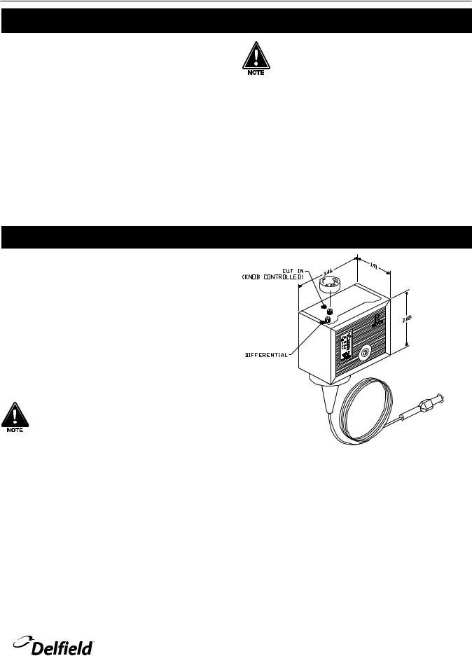
Pressure Control Settings
A pressure control controls temperature in the F18MC mega top, F18SC salad top, F18RC rail and F18DC rail.
The factory recommended low-pressure control settings are: 55psi cut-in and 30psi cut-out to maintain proper temperature for product. The interior temperature is controlled by the thermostat mounted in the mechanical compartment.
A pressure control is located in the machine compartment. An adjustable control has the word COLDER on the knob, with an arrow to indicate the adjustment direction. These controls are field adjustable and do not require a service agent.
In attempting to adjust the pressure control, you can do damage to your unit by accidentally adjusting the differential. Please make small incremental adjustments if a temperature adjustment is necessary, please contact the service department at Delfield (800) 733-8829 or your local service agent. Delfield is not responsible for charges incurred while having the pressure control adjusted.
Please make small incremental adjustments if a temperature adjustment is necessary. Contact the service department at Delfield +1 (989) 7737981 or your local service agent for additional assistance. Delfield is not responsible for charges incurred while adjusting the thermostat.
For customer service, call (800) 733-8829, (800) 773-8821, Fax (989) 773-3210, www.delfield.com |
9 |
 Loading...