

Page 1
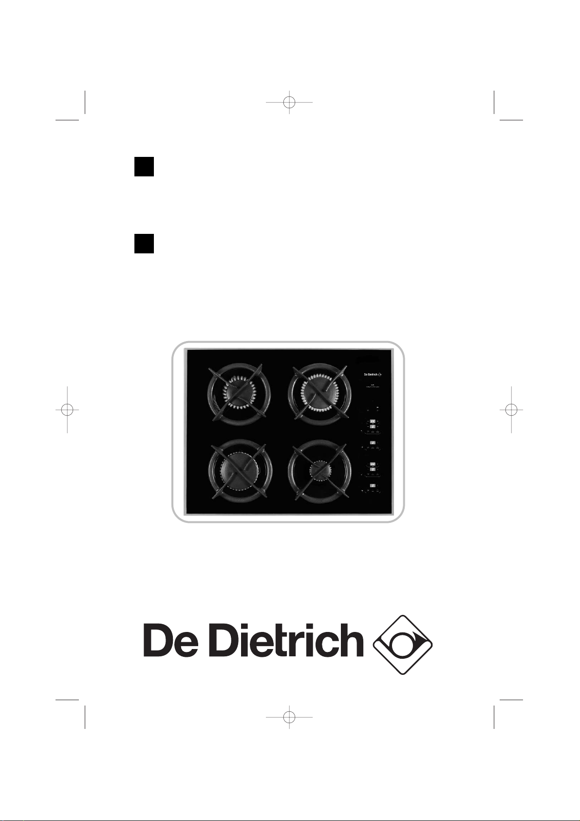
Le guide d’utilisation de
votre table de cuisson
Hob operating guide
FR
GB
99632241_FR_A.qxd 23/12/03 14:40 Page 1
Page 2
tout au long de la notice,
vous signale les consignes de sécurité,
vous signale les conseils et les astuces
Sommaire
Votre table en toute sécurité 4
Comment se présente votre table ? 5
Comment se présente votre clavier de
commande ?
6
Installez facilement votre table 7
Conseils d’encastrement 7-9
Raccordement électrique 10
Raccordement gaz 11-13
Changement de gaz 14-19
Utilisez votre table en toute simplicité 20
Comment mettre en marche et ajuster la puissance ? 20
Comment utiliser la minuterie ? 21
Quels sont les récipients les plus adaptés
sur les brûleurs gaz? 22
Comment entretenir votre table ? 23
Petites pannes et anomalies 24
Guide de cuisson gaz 26
2
FR
99632241_FR_A.qxd 23/12/03 14:40 Page 2
Page 3

3
Chère Cliente, Cher Client,
Vous venez d'acquérir une table DE DIETRICH et nous vous en
remercions.
Nos équipes de recherche ont conçu pour vous une nouvelle
génération d'appareils, qui par leur qualité, leur design et leurs
évolutions technologiques en font des produits d'exception et
révèle un savoir-faire unique.
Avec des lignes modernes et raffinées, votre nouvelle table
DE DIETRICH s'intègre harmonieusement dans votre cuisine et
allie parfaitement la maîtrise technologique, les performances de
cuisson, et le luxe esthétique.
Vous trouverez également dans la gamme des produits
DE DIETRICH, un vaste choix de fours, de hottes aspirantes, de
lave-vaisselle et de réfrigérateurs intégrables, que vous pourrez
coordonner à votre nouvelle table DE DIETRICH.
Bien entendu, dans un souci permanent de satisfaire au mieux vos
exigences vis à vis de nos produits, notre service consommateurs
est à votre disposition et à votre écoute pour répondre à toutes
vos questions ou suggestions (coordonnées à la fin de ce livret).
Grâce à ces "nouveaux objets de valeurs" qui nous servent de
repère dans nos vies de tous les jours, DE DIETRICH, référence
de l'excellence, est une véritable invitation à un nouvel art de
vivre.
La Marque DE DIETRICH.
Edito
99632241_FR_A.qxd 23/12/03 14:40 Page 3
Page 4
Nous avons conçu votre table de
cuisson pour une utilisation par des
particuliers dans un lieu d’habitation.
Dans le souci d’une amélioration
constante de nos produits, nous nous
réservons le droit d’apporter à leurs
caractéristiques techniques,
fonctionnelles ou esthétiques toutes
modifications de leurs
caractéristiques liées à l’évolution
technique.
Ces tables de cuisson destinées
exclusivement à la cuisson des
boissons et denrées alimentaires ne
contiennent aucun composant à base
d’amiante.
Les cuissons doivent être réalisées
sous votre surveillance.
Consultez la notice avant d’installer et
d’utiliser cet appareil.
Dans le cas où une fêlure
deviendrait visible sur le
dessus verre, débranchez
immédiatement l’appareil de
son alimentation et contactez
le Service Après-Vente.
Votre table en toute sécurité
4
Ne rangez pas dans le meuble situé
sous votre table de cuisson, vos
produits d’ENTRETIEN ou INFLAMMABLES
(atomiseur ou récipient sous
pression, ainsi que papiers, livres de
recettes...).
L’utilisation d’un appareil de cuisson
au gaz conduit à la production de
chaleur et d’humidité dans le local où
il est installé. Veillez à assurer une
bonne aération de votre cuisine.
Votre table doit être déconnectée de
l’alimentation (électrique et gaz)
avant toute intervention.
Par mesure de sécurité, après
utilisation, n’oubliez pas de fermer le
robinet de commande générale du
gaz distribué par canalisation ou le
robinet de la bouteille de gaz
butane/propane.
La marque de conformité
CE est ap-
posée sur ces tables.
Utilisez votre table en toute sécurité
VOTRE TABLE EST LIVRÉE PRÉ-RÉGLÉE POUR LE GAZ NATUREL.
99632241_FR_A.qxd 23/12/03 14:40 Page 4
Page 5
Le clavier de commande de cette table est équipé de commandes à touches
sensitives.
Pour se servir d’une touche de fonction...
Posez votre doigt bien droit et bien à plat sur la touche choisie jusqu’à ce que
l’afficheur indique le nouveau réglage.
5
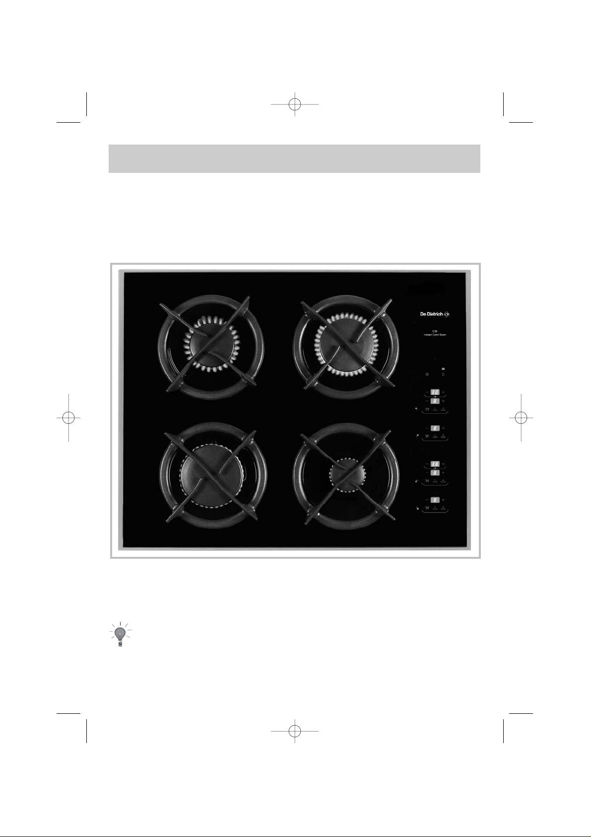
Comment se présente votre table ?
(*) Ces puissances sont exprimées en G20/20mbar.
Brûleur semi-rapide
1,5 kW*
Brûleur rapide
2,3 kW*
Brûleur grand rapide
3,1 kW*
Brûleur auxiliaire
0,85 kW*
99632241_FR_A.qxd 23/12/03 14:40 Page 5
Page 6
6
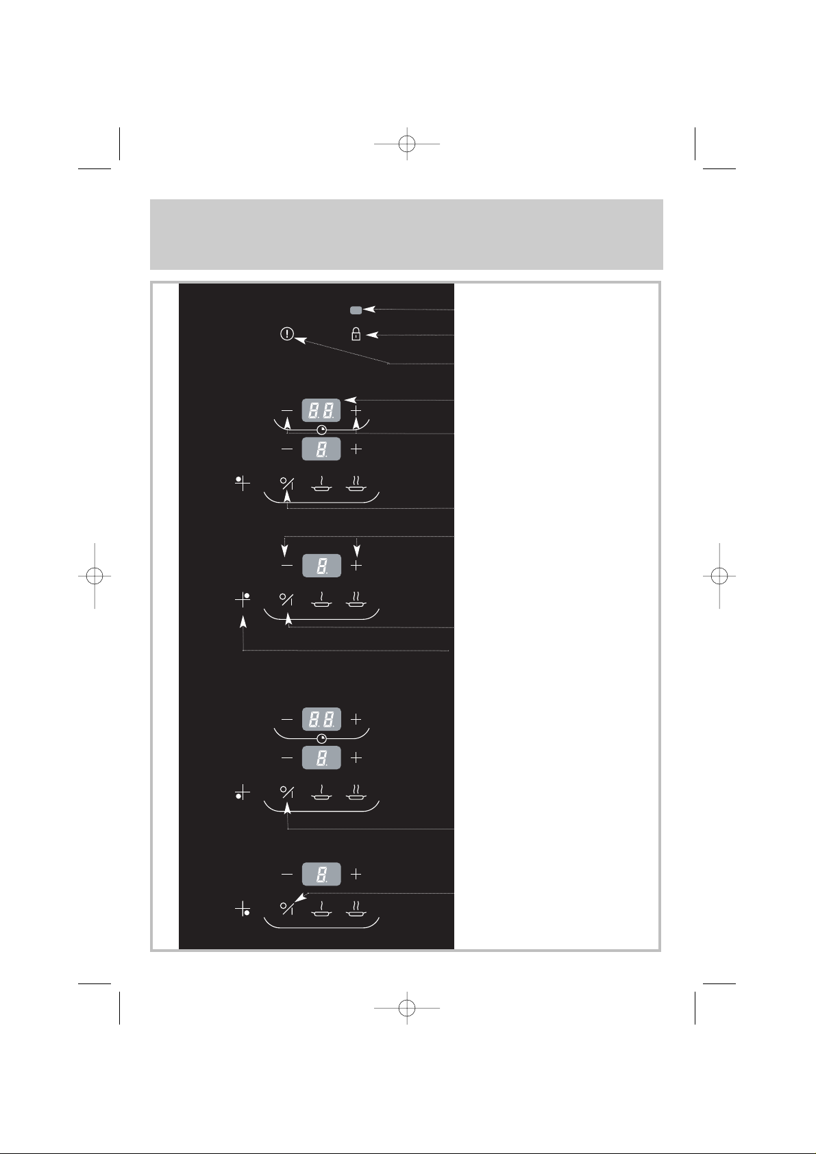
Comment se présente votre clavier
de commande ?
VOYANT DE VERROUILLAGE
TOUCHE DE VERROUILLAGE/DÉVERROUILLAGE
DU CLAVIER
R
EPERE FOYER
TOUCHE MARCHE/ARRET
FOYER ARRIERE GAUCHE
TOUCHE MARCHE/ARRET
FOYER ARRIERE DROIT
TOUCHE MARCHE/ARRET
FOYER AVANT GAUCHE
TOUCHE MARCHE/ARRET
FOYER AVANT DROIT
T
OUCHES DE RÉGLAGE DE
LA PUISSANCE DU BRULEUR
TOUCHE ARRET GÉNÉRAL
AFFICHAGE TEMPS MINUTERIE
RÉGLAGE MINUTERIE
99632241_FR_A.qxd 23/12/03 14:40 Page 6
Page 7
L’installation est réservée aux
installateurs et techniciens
qualifiés.
Avant l’installation, assurez-vous
que les conditions de distribution
locale (nature et pression du
gaz) et le réglage de l’appareil
sont compatibles.
Les conditions de réglage sont
inscrites sur une étiquette située dans
la pochette, ainsi que sur l'emballage.
N'étant pas raccordée à un dispositif
d'évacuation des produits de
combustion, elle doit être installée
conformément à la règlementation en
vigueur et utilisée dans un endroit
bien aéré. Une attention particulière
sera accordée aux dispositions en
matière de ventilation.
Installez facilement votre table
7
A ce sujet, la combustion n’étant
possible que grâce à l’oxygène de
l’air, il est nécessaire que cet air soit
renouvelé en permanence et que les
produits de la combustion soient
évacués (un débit d’air minimum de 2
m3/h par kW de puissance gaz est
nécessaire).
Exemple :
Puissance totale :
0,85 + 1,5 + 2,3 + 3,1 = 7,75 kW.
7,75 kW x 2 = 15,5 m3/h de débit
d’air minimum.
Ces tables sont conformes aux
échauffements des meubles selon la
norme EN 60335-2-6 et de classe 3
en ce qui concerne l’installation
(selon norme EN 30-1-1).
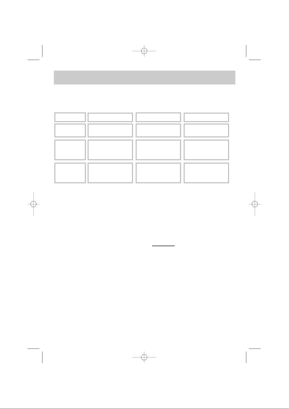
Conseils d’encastrement
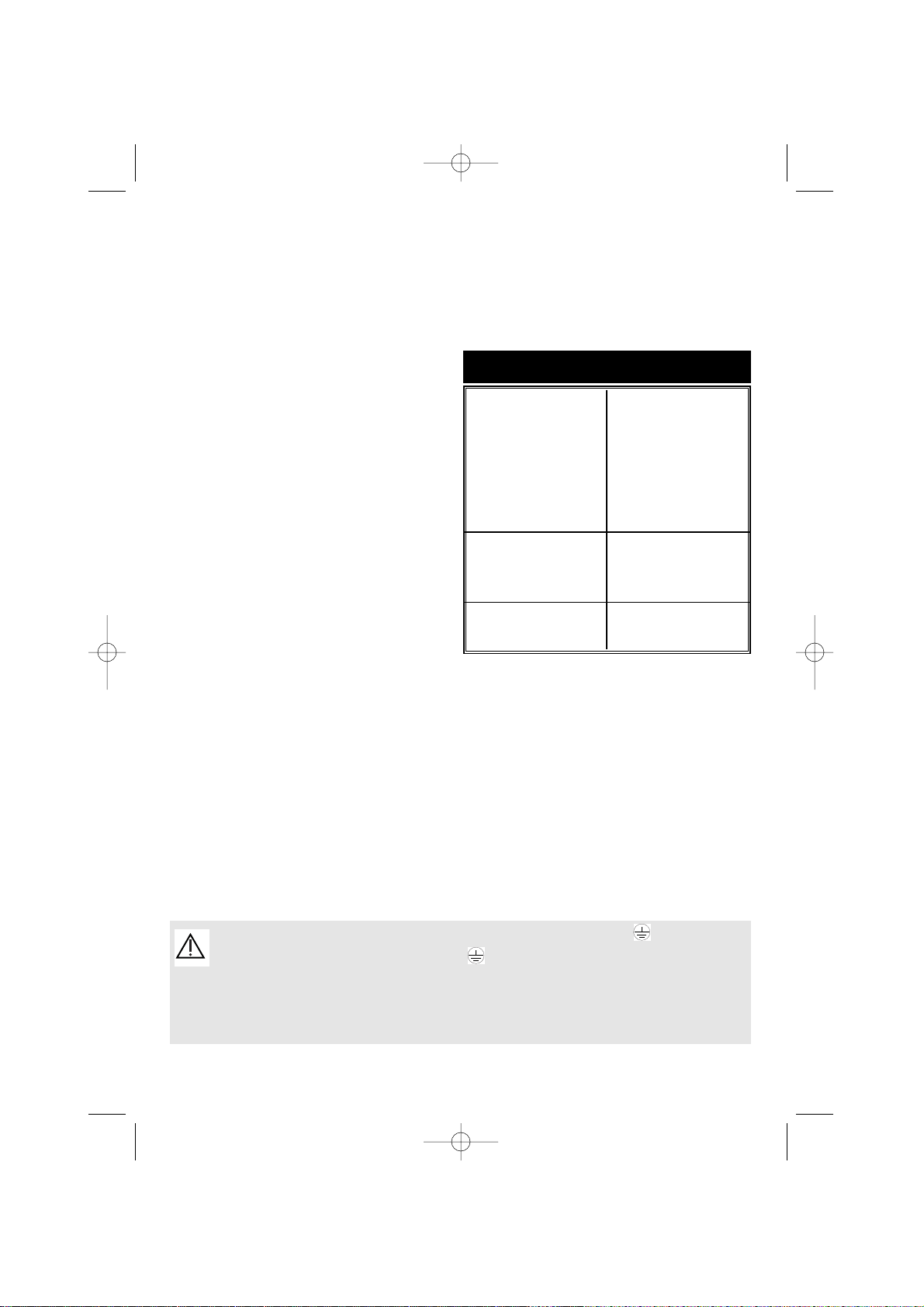
Largeur
Profondeur
Epaisseur
Découpe meuble
Modèle
56 cm 49 cm
Suivant meuble
Dimensions hors
tout au-dessus du
plan de travail
65 cm 51,8 cm 5 cm
Dimensions hors
tout au-dessous
du plan de travail
55 cm 47 cm 5,1 cm
99632241_FR_A.qxd 23/12/03 14:40 Page 7
Page 8
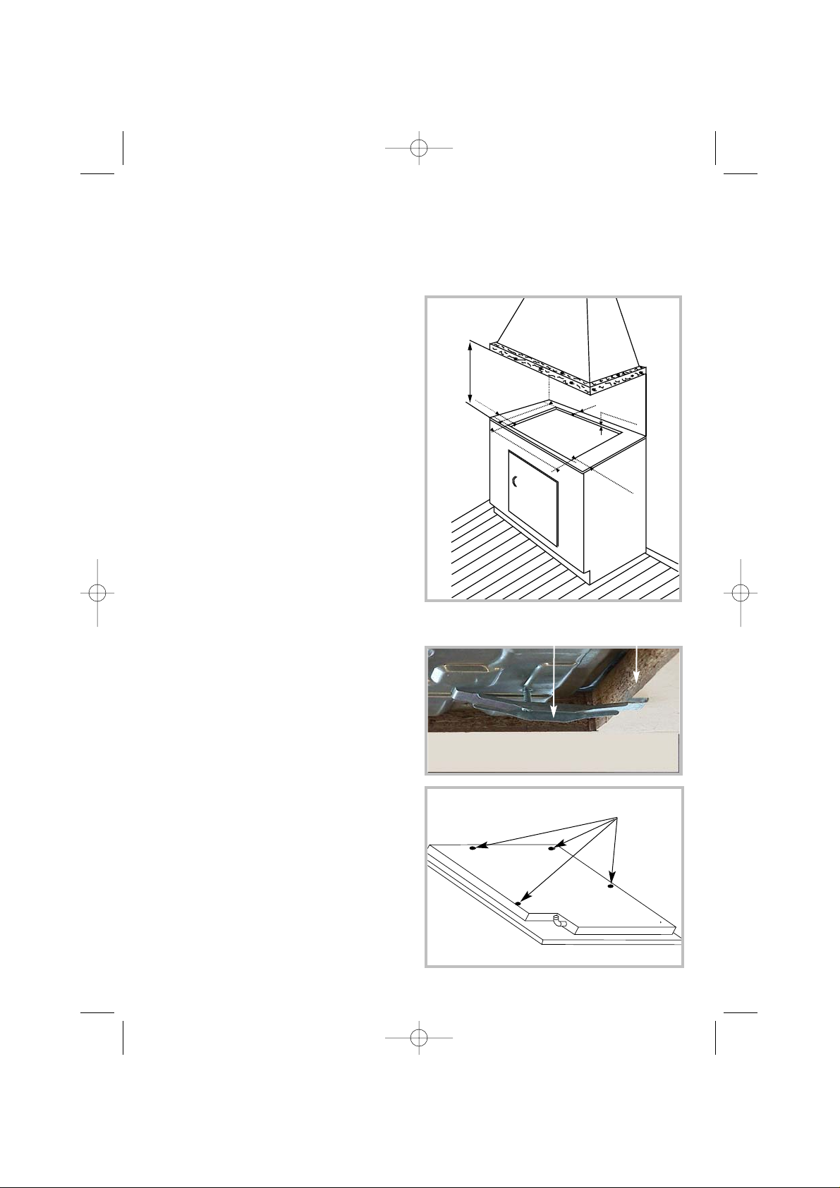
Installez facilement votre table
La table de cuisson doit être encastrée
dans le plateau d'un meuble support
de 3 cm d'épaisseur minimum, fait en
matière qui résiste à la chaleur, ou
bien revêtu d'une telle matière.
Pour ne pas gêner la manoeuvre des
ustensiles de cuisson, il ne doit y avoir
à droite, ou à gauche, ni meuble ni paroi à moins de 30 cm de la table de
cuisson.
Si une cloison horizontale est positionnée sous la table, celle-ci doit être
située impérativement entre 100 et
150 mm par rapport au-dessus du
plan de travail. Dans tous les cas, ne
rangez pas d’atomiseur ou de récipient sous pression dans le compartiment qui pourrait exister sous la table.
Placez la table de cuisson dans l’ouverture du meuble support en prenant
soin de tirer la table vers soi.
Placez les grilles support casserole, les
chapeaux, et les têtes de brûleurs.
Raccordez le câble d’alimentation de
la table à l’installation électrique de
votre cuisine (voir «Raccordement
électrique» de la table de cuisson).
Vous pouvez immobiliser, si vous le
désirez, la table au moyen de quatre
pattes livrées avec leur vis (voir schéma ci-contre) se fixant aux quatre
coins du caisson.
Utilisez impérativement les trous
prévus à cet effet.
Arrêtez de visser quand la patte
commence à se déformer.
Ne pas utiliser de visseuse.
Conseils d’encastrement (suite)
Patte de
fixation
Plan de
travail
8
trous de
fixation
99632241_FR_A.qxd 23/12/03 14:40 Page 8
70 cm mini
30 cm
m
5,3 cm mini
ini
49 cm
3 cm mini
56 cm
30 cm
m
ini
Page 9
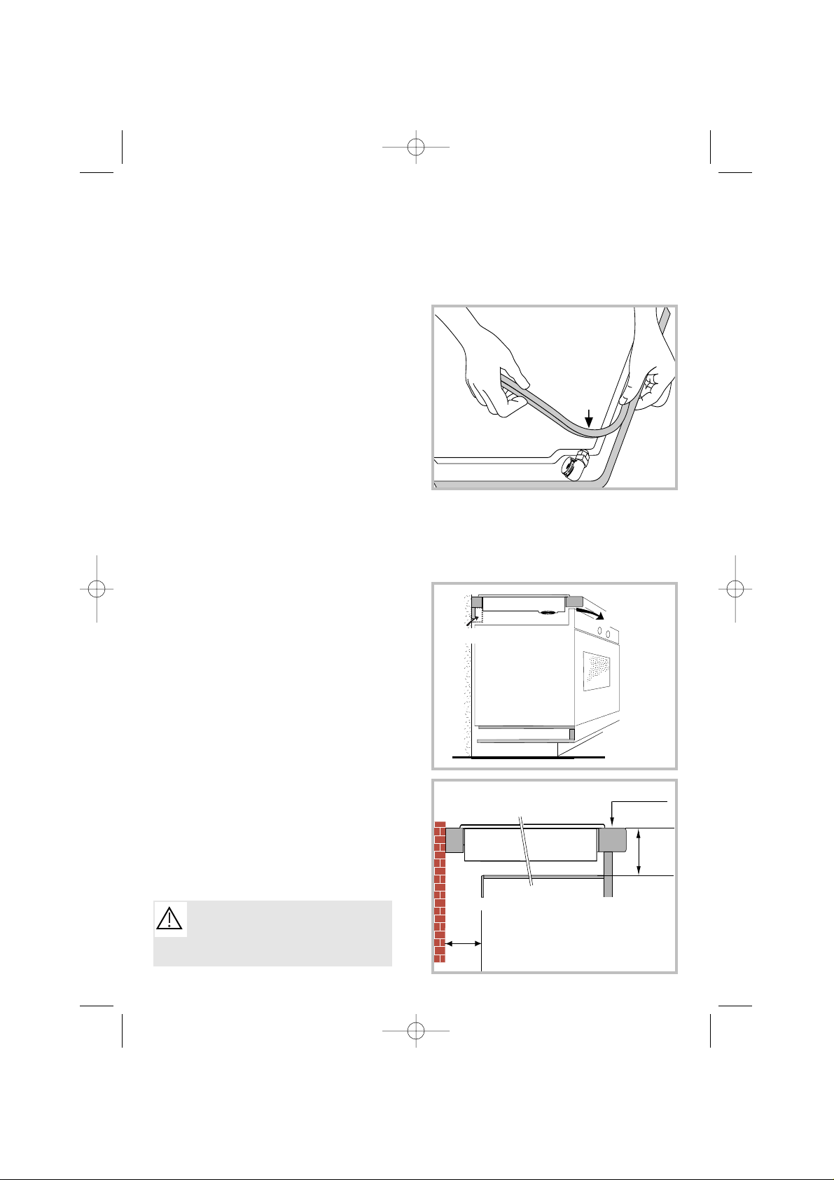
Installez facilement votre table
Pour assurer l'étanchéité entre le caisson et le plan de travail, collez le joint
mousse sur le pourtour extérieur
du cadre.
Collez le joint fourni dans la pochette
avant l’installation de la table :
1- Retirez les grilles support casserole, les chapeaux de brûleur et les têtes
de brûleurs en repérant leur position.
2- Retournez la table et posez-la avec
précaution au dessus de l’ouverture
du meuble pour ne pas endommager
les bougies d’allumage.
3- Collez le joint mousse, livré avec
l'appareil, sur le pourtour extérieur
du cadre. Ce joint assure l'étanchéité
entre le verre et le plan de travail.
4- Replacez les têtes de brûleurs, les
chapeaux de brûleurs et les grilles.
E
NCASTREMENT AU-DESSUS D’UN MEUBLE
AVEC PORTE OU TIROIR (voir dessin ci-
contre).
L’encastrement de votre table au-dessus d’un four nécessite que celui-ci
soit en position basse.
Il est déconseillé d’installer votre table
au-dessus d’un four dont la ventilation
ne s’effectue pas à l’avant.
Pratiquez sur la paroi droite ou gauche
du meuble du four, une entrée d’air de
40 cm
2
.
9
Conseils d’encastrement (suite)
Joint
Les sécurités thermiques de la
table interdisent son utilisation
simultanée avec un four en mode
pyrolyse.
Mini 4mm
Table gaz
Avant du
meuble
Vide
sanitaire
40 mm
mini
100 mm
mini
Plan de travail
Mini 40 cm
2
99632241_FR_A.qxd 23/12/03 14:40 Page 9
Page 10
H05V2V2F - T90
Section des
conducteurs
en mm
2
Fusible
220-240 V~ - 50 Hz
3 conducteurs dont
1 pour la terre
1
10 A
SECTION DU CABLE À UTILISER
10
Installez facilement votre table
Cette table de cuisson doit être raccordée sur le réseau 220-240 V~ monophasé par l’intermédiaire d’une prise de courant 2 pôles + terre normalisée CEI 60083 ou d’un dispositif à
coupure omnipolaire ayant une distance d’ouverture des contacts d’au
moins 3 mm.
La fiche de prise de courant doit être
accessible après installation.
Raccordement électrique
Le fil de protection (vert/jaune) est relié à la borne de terre de l’appareil
et doit être relié à la borne de terre de l’installation.
Si ce cordon d’alimentation est endommagé, il ne doit être remplacé que par le fabricant, son Service Après-Vente ou une personne de qualification similaire afin d’éviter
un danger.
● Table gaz
99632241_FR_A.qxd 23/12/03 14:40 Page 10
Page 11
Installez facilement votre table
Si la table de cuisson est installée audessus d'un four ou si la proximité
d'autres éléments chauffants risque
de provoquer un échauffement du
raccordement, il est impératif de réaliser celui-ci en tube rigide.
Si un tuyau flexible ou un tube souple
(cas du gaz butane) est utilisé, il ne
doit pas entrer en contact avec une
partie mobile du meuble ni passer
dans un endroit susceptible d'être encombré.
11
Raccordement gaz
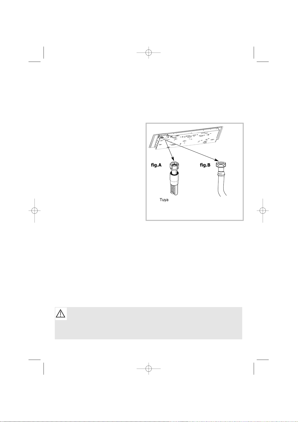
● Remarques préliminaires
fig.A fig.B
Tuyau flexible
métallique onduleux à
embouts mécaniques
Tuyau flexible à
embouts mécaniques
Le tuyau de raccordement doit rester visitable sur toute sa longueur et doit être
remplacé avant sa date limite d’utilisation (marquée sur le tuyau).
Quel que soit le moyen de raccordement choisi, assurez-vous de son étanchéité,
après installation, avec de l’eau savonneuse.
99632241_FR_A.qxd 23/12/03 14:41 Page 11
Page 12
12
Installez facilement votre table
Raccordement gaz (suite)
● Raccordements possibles
G
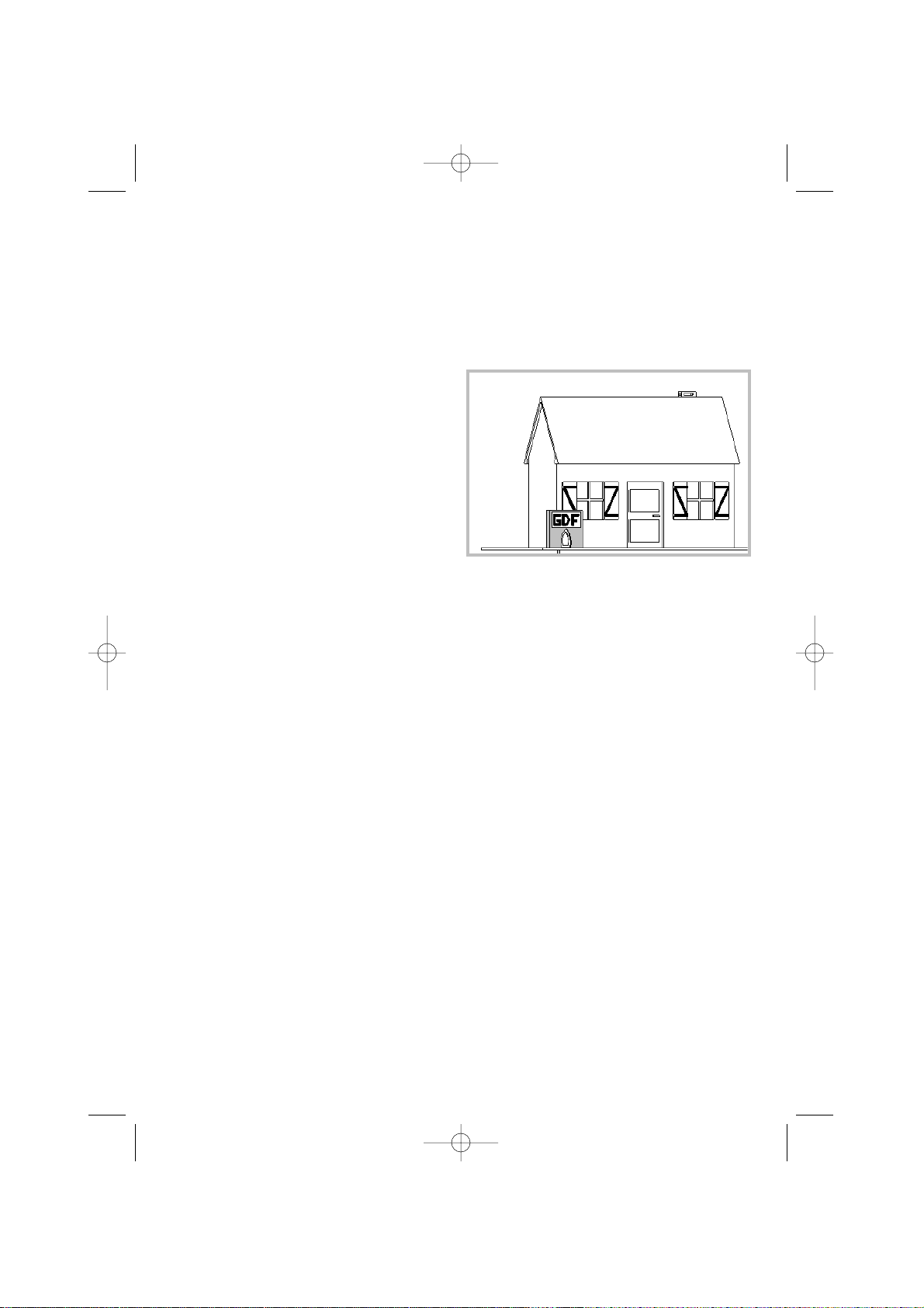
AZ DISTRIBUÉ PAR CANALISATION
(GAZ
NATUREL).
Choisir exclusivement l’un des 3 raccordements suivants :
-
le raccordement en tube rigide
(appellation norme gaz G1/2).
Réalisez le raccordement à l’extrémité
du coude monté sur l’appareil,
ou -
le raccordement par tuyau
flexible métallique onduleux à
embouts mécaniques
(fig. A de la
page précédente).
Vous pouvez utilisez un tuyau flexible
inox (type “Gazinox”) disponible auprès de votre Service Après-Vente,
ou
- le raccordement par tuyau
flexible à embouts mécaniques
(fig. B de la page précédente).
Ces tuyaux doivent avoir une lon-
gueur maximale de 2 mètres et
doivent être visitables sur toute la longueur.
GAZ NATUREL
Compteur
99632241_FR_A.qxd 23/12/03 14:41 Page 12
Page 13
Installez facilement votre table
13
Raccordement gaz (suite)
● Raccordements possibles
G
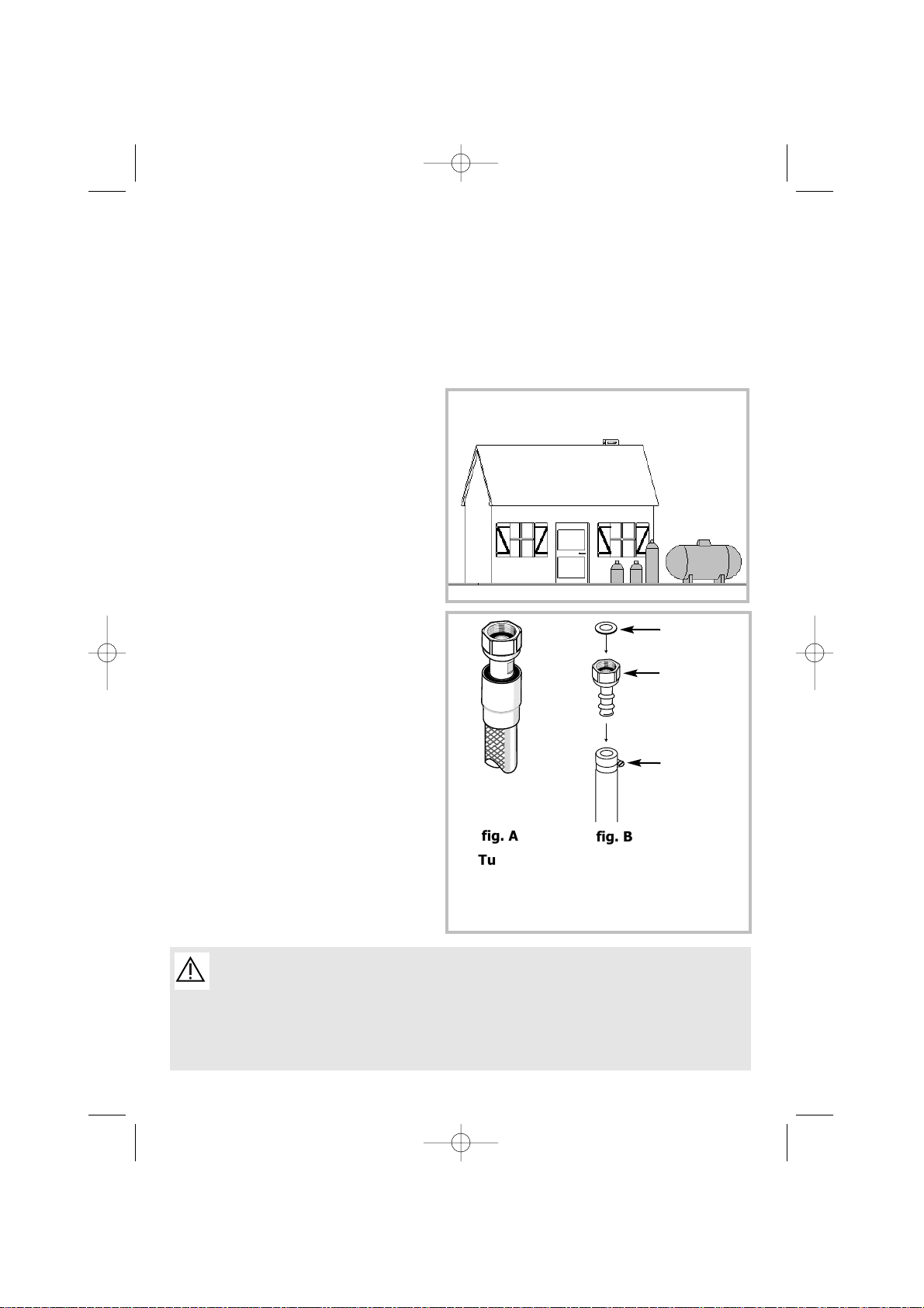
AZ DISTRIBUÉ PAR BOUTEILLE OU RÉ-
SERVOIR (GAZ BUTANE/PROPANE).
Pour la sécurité de l’utilisateur, nous
conseillons un raccordement soit en
tube rigide si cela est possible, soit
avec un tuyau flexible métallique onduleux (longueur maximum 2 mètres)
(fig. A).
Dans le cas d’une installation
existante ou le montage d’un tuyau
flexible est impossible, il est toujours
possible d’effectuer le raccordement
avec un tuyau souple (longueur maximum 2 mètres) muni des deux col-
liers de serrage : l’un sur l’about
(fig. B), et l’autre sur le détendeur,
sans oublier de mettre en place une
rondelle d’étanchéité entre l’about et
le coude de la table.
Vous trouverez l’about et la rondelle
d’étanchéité dans la pochette livrée
avec l’appareil.
BUTANE/PROPANE
Détendeur obligatoire
propane
butanene
propane
Pour éviter de provoquer un échauffement du raccordement supérieur à
30°C, vérifiez qu’il n’y ait pas d’éléments chauffants à proximité.
Vissez l’about avec un couple ne dépassant pas 2,5 m/daN (m/kgF).
En France, vous devez utiliser un tube ou un tuyau portant l’estampille NF Gaz.
Rondelle
d’étanchéité
(fournie)
About
(fourni)
Collier de
serrage
(non fourni)
fig. A
fig. B
Tuyau
flexible
métallique
onduleux à
embouts
Raccordement
en tuyau
souple
propane
99632241_FR_A.qxd 23/12/03 14:41 Page 13
Page 14

14
Installez facilement votre table
Changement de gaz
● Remarques préliminaires
Cette table de cuisson est livrée
pré-réglée pour le gaz naturel.
Les injecteurs nécessaires à l’adaptation au butane/propane ainsi que
l’about et la rondelle d’étanchéité sont
dans la pochette contenant la notice.
Reportez-vous au paragraphe “Rac-
cordement gaz” correspondant.
A chaque changement de gaz, cochez
la case correspondant au nouveau
gaz sur l’étiquette située dans la
pochette (voir tableau
“caractéristiques gaz” de ce même
chapitre).
99632241_FR_A.qxd 23/12/03 14:41 Page 14
Page 15
Installez facilement votre table
15
Changement de gaz (suite)
Lors de cette opération À EFFECTUER
AVANT TOUT BRANCHEMENT, vous devrez
successivement :
➊
Basculer l’interrupteur de
changement de gaz.
❷
Adapter le raccordement gaz.
❸
Changer les injecteurs.
➍
Branchement électrique
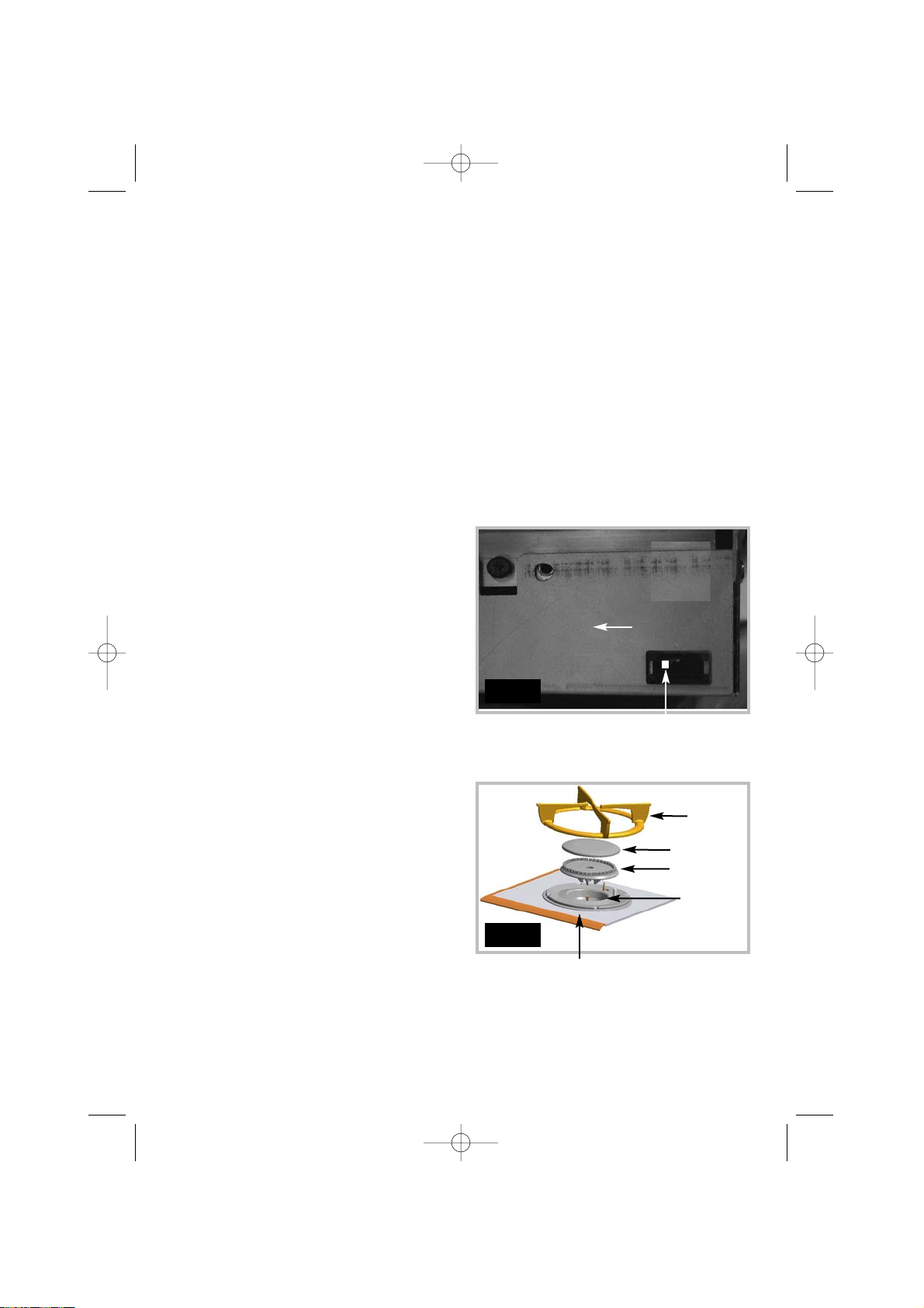
➊
BASCULEZ L’INTERRUPTEUR DE
CHANGEMENT DE GAZ.
Votre installation est alimentée en gaz
butane/propane. Vous devez basculer
l’interrupteur de changement de gaz
situé à l’avant droit de votre table en
position butane (fig. 1).
❷
A
DAPTEZ LE RACCORDEMENT
de la
table au nouveau réglage gaz. Reportez-vous au paragraphe “Raccorde-
ment gaz”.
❸
CHANGEZ LES INJECTEURS en procé-
dant comme suit :
•
Retirez les grilles, les chapeaux, et
les têtes de tous les brûleurs.
•
Dévissez à l’aide de la clé fournie
les injecteurs situés dans le fond de
chaque pot et ôtez-les (fig 2).
● Passage du gaz naturel en gaz
butane/propane.
INTERRUPTEUR
CHANGEMENT DE GAZ
BUTANE
GAZ DE RESEAU
(GAZ NATUREL)
Fig. 1
Chapeau
Tête
Pot
Grille
Dessus verre
Fig. 2
99632241_FR_A.qxd 23/12/03 14:41 Page 15
Page 16
16
Installez facilement votre table
Changement de gaz (suite)
•
Montez à la place les injecteurs
fournis dans la pochette, conformément au tableau des caractéristiques
gaz en fin de chapitre ; pour cela :
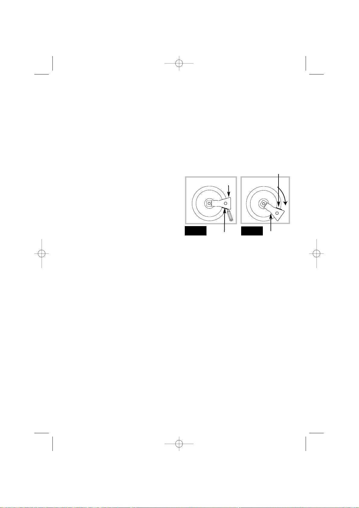
➪ Vissez-les d’abord manuellement
jusqu’au blocage de l’injecteur.
➪ Engagez à fond la clé sur l’injecteur.
➪ Tracez une ligne sur la plaque d’âtre
à l’aide d’un crayon à l’endroit indiqué
(fig. 3).
➪ Tournez la clé dans le sens des ai-
guilles d’une montre jusqu’à ce que la
ligne apparaisse de l’autre côté
(fig. 4). Attention ! Ne pas dépasser cette limite sous peine de
détérioration du produit.
•
Remontez les têtes, les chapeaux,
et les grilles de tous les brûleurs.
➍
BRANCHEZ le cordon électrique de
la table sur votre réseau (220-240 V~)
monophasé. Reportez-vous au paragraphe “Raccordement élec-
trique”.
● Passage du gaz naturel en gaz
butane/propane (suite).
Clé
Clé
Ligne
Ligne
Fig. 4
Fig. 3
V
OTRE TABLE EST À PRÉSENT PRETE À FONCTIONNER EN GAZ
BUTANE
/PROPANE.
99632241_FR_A.qxd 23/12/03 14:41 Page 16
Page 17

17
Installez facilement votre table
Changement de gaz (suite)
Lors de cette opération À EFFECTUER
AVANT TOUT BRANCHEMENT, vous devrez
successivement :
➊
Basculer l’interrupteur de
changement de gaz.
❷
Adapter le raccordement gaz.
❸
Changer les injecteurs.
➊
BASCULEZ L’INTERRUPTEUR DE
CHANGEMENT DE GAZ.
Votre installation est alimentée en gaz
naturel. Vous devez basculer l’interrupteur de changement de gaz situé à
l’avant droit de votre table en position
gaz de réseau (gaz naturel) (fig. 1).
❷
ADAPTEZ LE RACCORDEMENT de la
table au nouveau réglage gaz. Reportez-vous au paragraphe “Raccorde-
ment gaz”.
❸
CHANGEZ LES INJECTEURS en procé-
dant comme suit :
•
Retirez les grilles, les chapeaux, et
les têtes de tous les brûleurs.
•
Dévissez à l’aide de la clé fournie
les injecteurs situés dans le fond de
chaque pot et ôtez-les (fig 2).
● Passage du gaz Butane/Propane
au gaz naturel
Chapeau
Tête
Pot
Grille
Dessus verre
INTERRUPTEUR
CHANGEMENT DE GAZ
BUTANE
GAZ DE RESEAU
(GAZ NATUREL)
Fig. 1
Fig. 2
99632241_FR_A.qxd 23/12/03 14:41 Page 17
Page 18

18
Installez facilement votre table
Changement de gaz (suite)
•
Montez à la place les injecteurs
fournis dans la pochette, conformément au tableau des caractéristiques
gaz en fin de chapitre ; pour cela :
➪ Vissez-les d’abord manuellement
jusqu’au blocage de l’injecteur.
➪ Engagez à fond la clé sur l’injecteur.
➪ Tracez une ligne sur la plaque d’âtre
à l’aide d’un crayon à l’endroit indiqué
(fig. 3).
➪ Tournez la clé dans le sens des ai-
guilles d’une montre jusqu’à ce que la
ligne apparaisse de l’autre côté (fig.
4). Attention ! Ne pas dépasser
cette limite sous peine de détérioration du produit.
➪ Remontez les têtes, les chapeaux et
les grilles de tous les brûleurs.
● Passage du gaz Butane/Propane
au gaz naturel
Clé
Clé
Ligne
Fig. 4
Fig. 3
VOTRE TABLE EST À PRÉSENT PRETE À FONCTIONNER EN GAZ
DE RÉSEAU
(GAZ NATUREL).
Ligne
99632241_FR_A.qxd 23/12/03 14:41 Page 18
Page 19

19
Installez facilement votre table
Changement de gaz (suite)
● Caractéristiques gaz
Gaz Naturel
94 121
137 63
62 78
88 45
Le tableau ci-contre indique les implantations des injecteurs sur votre appareil en fonction du
gaz utilisé. Chaque numéro est marqué sur l’injecteur.
Gaz
butane/Propane
ELECTRICITE
REPÉRAGE DES INJECTEURS
- Alimentation : 220-240 V~ - 50 Hz
- Consommation en veille : 2,5 Wh
- Consommation maxi en fonction : 20 Wh
FR-GB FR-GB FR-GB
FR
ES-PT ES-PT ES-PT
Appareil destiné à être installé en : Butane Propane Gaz Gaz
FR ....................................Cat : II2E+3+ naturel naturel
GB - ES - PT .....................Cat : II2H3+
G30 G31 G20 G25
Débit horaire ci-dessous : 28-30 mbar 37 mbar 20 mbar 25 mbar
à 15°C sous 1013 mbar
Brûleur rapide
Repère marqué sur l'injecteur 78 78 121 121
Débit calorifique nominal (kW) 2,25 2,25 2,30 2,30
Débit calorifique réduit (avec sécurité) (kW) 0,830 0,870
Débit horaire (g/h) 164 161
Débit horaire (l/h) 219 255
Brûleur grand rapide
Repère marqué sur l'injecteur 88 88 137 137
Débit calorifique nominal (kW) 3,10 3,10 3,10 3,10
Débit calorifique réduit (avec sécurité) (kW) 0,830 0,870
Débit horaire (g/h) 225 221
Débit horaire (l/h) 295 343
Brûleur semi-rapide
Repère marqué sur l'injecteur 62 62 94 94
Débit calorifique nominal (kW) 1,45 1,45 1,5 1,5
Débit calorifique réduit (avec sécurité) (kW) 0,620 0,615
Débit horaire (g/h) 105 104
Débit horaire (l/h) 143 166
Brûleur auxiliaire
Repère marqué sur l'injecteur 45 45 63 63
Débit calorifique nominal (kW) 0,750 0,750 0,850 0,850
Débit calorifique réduit (avec sécurité) (kW) 0,300 0,350
Débit horaire (g/h) 55 54
Débit horaire (l/h) 81 94
Table 65 cm 4 feux gaz
Débit calorifique total (kW) 7,55 7,55 7,75 7,75
Débit maximum (g/h) 549 540
(l/h) 738 858
99632241_FR_A.qxd 23/12/03 14:41 Page 19
Page 20

20
•
Sélectionnez le brûleur que vous
souhaitez utiliser en appuyant sur la
touche correspondante (fig. 1).
➡ Le voyant de fonctionnement du
brûleur s’allume.
➡ Les voyants de puissance de ce
brûleur clignotent.
•
Choisissez la puissance de chauffe
en appuyant au choix sur les touches de
réglage de la puissance du brûleur
(fig. 2). Les voyants de puissance s’arrêtent de clignoter ; votre table s’allume
alors automatiquement.
•
Vous pouvez ajuster la puissance
du brûleur en appuyant sur les touches
ou .
Cette puissance est visualisée par les
voyants d’indication de puissance.
➡ Un appui sur sélectionne
la position 7 (fig 3).
➡ Un appui sur sélectionne
la position 5 (fig. 4).
•
Verrouillage : appuyez environ 3 se-
condes sur la commande . Les commandes sont bloquées,
sauf la commande marche/arrêt des
brûleurs et la touche arrêt général. Après
les 3 secondes, le voyant d’indicateur de
verrouillage s’allume.
•
Déverrouillage : appuyez environ 3
secondes sur la commande (fig. 5).
L’indicateur s’éteint. La table retrouve la
validité de toutes les commandes.
Utilisez votre table en toute simplicité
Comment mettre en marche et ajuster la puissance ?
- En cas d’extinction accidentelle (exemple : courants d’air), votre table est équipée d’un
système de réallumage automatique . Celui-ci est limité à 2 réallumages.
- Vous pouvez arrêter immédiatement tous les brûleurs en fonctionnement en utilisant la
touche d’arrêt général .
- Les flammes du brûleur sont plus petites au niveau des doigts de grille pour protéger l’émail de la grille.
Fig. 3
Fig. 2
Fig. 1
Fig. 4
Fig. 5
Après une utilisation intensive, la zone
de cuisson peut rester chaude
quelques minutes.
Un “
H”
H”
s’affiche durant cette période.
Evitez alors de toucher les zones
concernées.
•
Indicateur de chaleur résiduelle
99632241_FR_A.qxd 23/12/03 14:41 Page 20
Page 21

21
•
Les brûleurs avant gauche et
arrière gauche sont équipés d’une
minuterie (durée maximale de 99 minutes). Toutefois, ils peuvent fonctionner sans celle-ci.
•
Allumez le brûleur comme indi-
qué dans la page précédente “Com-
ment mettre en marche et ajuster la puissance ?”.
•
Appuyez sur la touche de la
minuterie.
Dès que vous appuyez sur la
touche , la minuterie se met en
service et la durée (en minutes) défile sur l’affichage.
•
Maintenez votre doigt jusqu’à la
durée souhaitée.
Lorsque le temps est écoulé, le brûleur
s’éteint, l’affichage de la minuterie clignote sur .
Vous entendez alors des “bips” discontinus. Pour les arrêter : appuyez sur
n’importe quelle touche de commande
de minuterie.
•
Pour modifier la durée de cuis-
son, vous pouvez appuyer à tout instant sur la touche ou .
•
Pour arrêter la minuterie, ap-
puyez sur la touche jusqu’à l’extinction de l’affichage sur la minuterie. Le brûleur continue de fonctionner sans la minuterie.
Utilisez votre table en toute simplicité
Comment utiliser la minuterie ?
- Pendant la dernière minute, le déccompte s’affiche en secondes.
- Lorsque le temps de cuisson est écoulé, le brûleur s’éteint automatiquement (l’arrivée
de gaz dans le brûleur est alors coupée).
Fig. 1
99632241_FR_A.qxd 23/12/03 14:41 Page 21
Page 22

22
Utilisez votre table en toute simplicité
Quels sont les récipients les plus adaptés sur les brûleurs gaz ?
•
Diamètres de récipients conseillés :
Réglez la couronne de flammes de
façon que celles-ci ne débordent pas
du pourtour du récipient.
N'utilisez pas de récipient à fond
concave ou convexe.
Ne laissez pas fonctionner un foyer
gaz avec un récipient vide.
N’utilisez pas des récipients qui recou-
BON
MAUVAIS
CONVEXE
CONCAVE
- Maintenez ouverts les orifices d’aération naturelle, ou installez un dispositif d’aération mécanique (hotte de ventilation mécanique).
- Une utilisation intensive et prolongée de l’appareil peut nécessiter une aération supplémentaire, par exemple en ouvrant une fenêtre, ou une aération plus efficace, par
exemple en augmentant la puissance de la ventilation mécanique si elle existe (un débit
d’air minimum de 2 m3/h par kW de puissance gaz est nécessaire).
Exemple pour cette table :
Puissance totale : 0,85 + 1,5 + 2,3 + 3,1 = 7,75 kW.
7,75 kW x 2 = 15,5 m3/h de débit minimum.
- L’utilisation d’un appareil de cuisson au gaz conduit à la production de chaleur et d’humidité dans le local où il est installé. Veillez à assurer une bonne aération de votre cuisine.
- Par mesure de sécurité, après utilisation, n’oubliez pas de fermer le robinet de
commande générale du gaz de réseau ou le robinet de la bouteille de gaz butane/propane.
Grand brûleur
GRAND RAPIDE
18 à 28 cm
Brûleur moyen
RAPIDE
16 à 22 cm
SEMI-RAPIDE
12 à 20 cm
AUXILIAIRE
8 à 14 cm
Petits brûleurs
99632241_FR_A.qxd 23/12/03 14:41 Page 22
Page 23

➡ En cas d’encrassement des
bougies d’allumage, nettoyezles à l’aide d’une petite brosse à
poils durs (non métallique).
➡ L’injecteur gaz se trouve au
centre du brûleur en forme de
pot. Veillez à ne pas l’obstruer
lors du nettoyage, ce qui perturberait les performances de
votre table. En cas d’obstruction, utilisez une épingle à nourrice pour déboucher l’injecteur.
23
- Dans le cas où une fêlure ou une fissure deviendrait visible sur le
dessus verre, débranchez immédiatement l’appareil de son alimentation et contactez le Service Après-Vente.
- Préférez un nettoyage des éléments de la table à la main plutôt qu’au
lave-vaisselle.
- N’utilisez pas d’éponge grattante pour nettoyer votre table de cuisson.
- N’utilisez pas de nettoyeur vapeur.
Thermocouple
Ecrou
Injecteur
Bougie
PRODUITS ET
ACCESSOIRES A
UTILISER
✓ Petite brosse à poils durs.
✓ Crème à récurer douce.
✓ Eponge sanitaire.
L’entretien de votre table de cuisson est facilité si vous l’effectuez avant son
refroidissement complet. Cependant, ne nettoyez jamais votre appareil pendant son
fonctionnement. Mettez à zéro toutes les commandes.
COMMENT
PROCÉDER ?
➤➤
Entretien des
bougies et des
injecteurs
➡ Dans le cas de taches persistantes, utilisez une crème non
abrasive, puis rincez à l’eau
claire. Essuyez soigneusement
chaque pièce du brûleur avant
de réutiliser votre table de
cuisson.
➤➤
Entretien des
grilles et des
brûleurs gaz
✓ Eponge sanitaire.
✓ Produits spéciaux verre vi-
trocéramique (ex. : Cera-clen).
➡ Nettoyez avec de l’eau chaude, puis essuyez. Dans le cas
de taches persistantes, utilisez
des produits spéciaux verre vitrocéramique.
➤➤
Entretien du
desus verre
Comment entretenir votre table ?
99632241_FR_A.qxd 23/12/03 14:41 Page 23
Page 24

24
Vous avez un doute sur le bon fonctionnement de votre table ....
...... ceci ne signifie
pas forcément qu'il y a une panne. Dans tous les cas, vérifiez les points suivants :
QUE SE PASSE-T-IL ?
QUE FAIRE ?
CODES
ERREUR
➡ C’est la procédure de mise sous tension de votre table.
➡ Si vous avez appuyé sur la touche
d’arrêt général ; ceci est normal.
✓ Attendez quelques secondes que l’affichage sur s’éteigne.
✓ Votre table est prête à l’utilisation.
➤ 2 bips puis affichage
de F1 ou F2 ou F3 ou F...
sur la minuterie ,
puis affichage
de A1 ou A2 ou A...
➡ Coupure de courant.
✓ Vérifiez que vous avez du courant.
✓ Si vous avez du courant et que le dé-
faut persiste, appelez le Service AprèsVente.
➤ Vous n’arrivez pas à
commander votre table et
les afficheurs n’indiquent
rien.
➡ Votre brûleur ne parvient pas à s’allumer.
✓ Vérifiez que le gaz est bien ouvert ou
que les brûleurs sont correctement assemblés.
✓ Vérifez que les injecteurs correspondent au gaz utilisé (voir tableau des caractérisques techniques).
✓ Vérifiez qu’il y a bien des étincelles
sur le brûleur correspondant.
✓ Après toutes ces vérifications, renouvelez la mise en marche en appuyant
sur .
➤ affiche E4 et la
table émet un bip.
Un des voyants du brûleur en défaut s’allume.
➡ Vous avez eu une coupure de courant ou vous avez utilisé la touche
d’arrêt général .
✓ Appuyez sur pour utiliser
normalement votre table.
➤ affiche un
temps qui clignote.
(Temps restant avant la
coupure de courant).
➡ Le brûleur concerné est inutilisable.
➡ vous pouvez cependant utiliser les
autres brûleurs.
✓ Appelez votre Service Après-Vente en
lui précisant le code erreur affiché.
➡ Votre table est inutilisable.
✓ Coupez le gaz.
✓ Appelez votre Service Après-Vente en
lui précisant le code erreur affiché.
➤ affiche E6.
Petites pannes et anomalies
➡ Vous avez une flamme ou un corps
chaud sur l’élément de sécurité (thermocouple).
✓ Coupez le gaz.
✓ Appelez votre Service Après-Vente.
➤ affiche E7 : un
des voyants s’allume
pour signaler le brûleur
en défaut.
➡ La table possède 2 défauts.
✓ Appelez votre Service Après-Vente en
précisant les voyants allumés.
➤ affiche EE et
plusieur voyants s’allument pour signaler les
brûleurs en défaut.
- L’affichage d’un code erreur bloque automatiquement l’utilisation de
la minuterie .
➤ affiche E2 ou
E5, un des voyants du
brûleur en défaut clignote
et un bip est émis.
99632241_FR_A.qxd 23/12/03 14:41 Page 24
Page 25

25
QUE SE PASSE-T-IL ?
QUE FAIRE ?
➡ Allumage des brûleurs :
Il n’y a pas d’étincelles lors de l’appui sur les touches.
✓ Vérifiez le branchement électrique de la table de
cuisson.
✓ Vérifiez la propreté des bougies d’allumage.
✓ Vérifiez la propreté et le bon assemblage des brûleurs.
➡ Lors de l’allumage d’un brûleur, il y a des étincelles
sur tous les brûleurs à la fois.
✓ C’est normal. La fonction allumage est centralisée et
commande tous les brûleurs simultanément.
➡ Il y a des étincelles, mais le ou les brûleurs ne
s’allument pas.
✓ Vérifiez que le tuyau d’arrivée de gaz n’est pas pincé.
✓ Vérifiez que la longueur d’arrivée de gaz est inférieure
à 2 mètres.
✓ Vérifiez l’ouverture de l’arrivée de gaz.
✓ Si vous avez du gaz en bouteille ou en citerne, vérifiez
que celle-ci ne soit pas vide.
✓ Si vous venez d’installer la table ou de changer la bou-
teille de gaz, renouvelez plusieurs fois les opérations
d’allumage jusqu’à l’arrivée du gaz dans les brûleurs.
✓ Vérifiez que l’injecteur n’est pas bouché, et si c’est le
cas, débouchez-le avac une épingle à nourrice.
✓ Allumez votre brûleur avant d’y poser votre casserole.
➡ Au ralenti, le brûleur s’éteint ou bien les flammes
restent importantes.
✓ Evitez les courants d’air violents dans la pièce.
✓ Vérifiez la correspondance entre le gaz utilisé et les in-
jecteurs installés (voir le repérage des injecteurs dans le
chapitre “Caractéristiques gaz”.
Rappel : les tables de cuisson sont livrées d’origine en
gaz de réseau (gaz naturel).
✓ Vérifiez que l’interrupteur changement de gaz est correctement positionné (voir paragraphe “Changement
de gaz”).
✓ Appelez le Service Après-Vente pour le réglage des
brûleurs au ralenti.
Petites pannes et anomalies (suite)
➡ Les flammes ont un aspect irrégulier.
✓ Vérifiez la propreté des brûleurs et des injecteurs si-
tués sous les brûleurs, l’assemblage des brûleurs, etc...
✓ Vérifiez qu’il reste suffisamment de gaz dans votre
bouteille.
99632241_FR_A.qxd 23/12/03 14:41 Page 25
Page 26

PREPARATIONS TEMPS GRAND RAPIDE SEMI- AUXILIAIRE
RAPIDE RAPIDE
SOUPES Bouillons 8-10 minutes X
Potages épais X
POISSONS Court-bouillon 8-10 minutes X
Grillés 8-10 minutes X
SAUCES Hollandaise, béarnaise XX
Béchamel, aurore 10 minutes XX
LÉGUMES Endives, épinards X
Petits pois cuisinés 25-30 minutes XX
Tomates provençales 15-20 minutes XX
Pommes de terre rissolées XX
Pâtes X
VIANDES Steack X
Blanquette, Osso-bucco 90 minutes X
Escalope à la poêle 10-12 minutes X
Tournedos (gril fonte) 10 minutes X
FRITURE Frites X
Beignets X
DESSERTS Riz au lait 25 minutes X
Compotes de fruits XX
Crêpes 3-4 minutes XX
Chocolat 3-4 minutes X
Crème anglaise 10 minutes X
26
Guide de cuisson
- Pour régler au mieux votre temps de cuisson, n’hésitez pas à passer le récipient d’un
brûleur à l’autre (par exemple : du brûleur grand rapide au brûleur semi-rapie : blanquette, osso-bucco...).
- Pour les grillades nécessitant une forte température, choisissez le brûleur grand rapide.
- Pour les sauces délicates et le réchauffage de plats cuisinés, utilisez le brûleur
semi-rapide.
99632241_FR_A.qxd 23/12/03 14:41 Page 26
Page 27

27
In this Manual,
displays safety instructions
displays tips and hints
List of contents
Using your hob in complete safety 29
What your hob looks like? 30
What the control board looks like? 31
Installing your hob in all simplicity 32
Fitting recommendations 32-34
Electrical connections 35
Gas connections 36-38
Changing the type of gas supply 39-44
Using your hob in all simplicity 45
Turning on the hob and adjusting the power setting 45
How to use the timer? 46
Which pans are best adapted for use
on the gas burner? 47
How to look after your hob? 48
Minor troubleshooting 49
Gas-cooking guide 51
GB
99632241_FR_A.qxd 23/12/03 14:41 Page 27
Page 28

28
Dear Customer,
Thank you for buying a DE DIETRICH hob.
Our research teams have designed a new generation of kitchen
appliances. As a result of our unique expertise, we have produced
a range of goods whose quality, design and technical advance are
unsurpassed.
You will find that the clean lines and modern look of your
DE DIETRICH hob blends in perfectly with your kitchen décor. It
is easy to use and performs to a high standard.
DE DIETRICH also makes a range of products that will enhance
your kitchen such as hobs, extractor hoods, built-in dishwashers
and refrigerators. There are models to complement your new
DE DIETRICH hob.
Of course, we make every effort to ensure that our products meet
all your requirements, and our Customer Relations department is
at your disposal, to answer all your questions and to listen to all
your suggestions (see back cover of manual).
DE DIETRICH is certain that by setting new standards of
excellence by which comparisons can be made, customers will
find that DE DIETRICH appliances offer a better and more
exciting way of living.
DE DIETRICH.
Editorial
99632241_FR_A.qxd 23/12/03 14:41 Page 28
Page 29

29
We have designed your hob for
private domestic use.
With a view to the constant
improvement of our products, we
reserve the right to make any
changes in their technical, functional
or aesthetic characteristics as a result
of technical evolution.
These hobs are designed exclusively
for the cooking of drinks and
foodstuffs. These products do not
contain any asbestos-based
component parts.
You must always keep an eye on your
cooking.
Please read the instructions before
installing and using this appliance.
Should a crack appear on the
glass, disconnect your
appliance immediately and
contact your After-Sales Service.
Your hob in complete safety
Never leave any CLEANING OU
INFLAMMABLE
products in the
cupboard or drawer beneath your
hob (aerosols or other pressurised
cans, papers, recipe books, etc.).
Using a gas-powered hob produces
both heat and humidity in the room
where it is used. Make sure your
kitchen is well ventilated.
Disconnect your hob from both
electrical and gas supplies before
carrying out any maintenance
operations.
For safety reasons, do not forget to
close the main gas valve for built in
gas lines or the valve on the top of
your butane/propane gas cylinder.
The EC mark of conformity can be
found on all these hobs.
Using your hob in complete safety
YOUR HOB IS DELIVERED PRE-SET FOR USE WITH NATURAL TOWN GAS.
99632241_FR_A.qxd 23/12/03 14:41 Page 29
Page 30

The control panel for this hob is equipped with touch sensitive controls.
To use one of the touch controls you should…
Place your finger flat and straight on the chosen button until the display shows the
new setting.
30
What your hob looks like?
(*) These power settings are expressed in G20/20mbar.
Semi-fast burner
1,5 kW*
Fast burner
2,3 kW*
Extra-fast burner
3,1 kW*
Auxiliary burner
0,85 kW*
99632241_FR_A.qxd 23/12/03 14:41 Page 30
Page 31

31
What the control board looks like?
THE "LOCK" INDICATOR
BUTTON FOR LOCKING/UNLOCKING THE
KEYPAD
RING INDICATOR
ON/OFF TOUCH CONTROL
B
ACK LEFT-
HAND RING
ON/OFF
TOUCH CONTROL
BACK RIGHT-HAND RING
ON/OFF touch control
F
RONT LEFT-HAND RING
ON/OFF touch control
FRONT RIGHT-HAND RING
BUNER POWER
ADJUSTMENT BUTTONS
MAIN "OFF" SWITCH
TIMER DISPLAY
TIMER SETTING
99632241_FR_A.qxd 23/12/03 14:41 Page 31
Page 32

32
This appliance should be
installed by a qualified
technician / installer.
Prior to installation, ensure that
the local distribution conditions
(nature of the gas and gas
pressure) and the adjustment
conditions of the appliance are
compatible.
The adjustment conditions are stated
on a label in the wallet and also on
the packaging.
Since this appliance is not connected
to a combustion products evacuation
device, it must be installed in
accordance with current installation
regulations and used in a wellventilated place. Particular attention
should be given to the relevant
requirements regarding ventilation.
Installing your hob in all simplicity
On this subject, combustion can take
place only if oxygen from the air is
present, so this air must be
constantly renewed and the
combustion products must be
evacuated (a minimum air input of 2
m3/hour per kw of gas energy is
required).
E.g. :
Total power :
0,85 + 1,5 + 2,3 + 3,1 = 7,75 kW.
7,75 kW x 2 = 15,5 m3/h minimum
airflow.
These hobs have type X protection
(in accordance with standard EN
60.335.2.6) against overheating of
cupboards and Class 3 for installation
itself (in accordance with standard EN
30.1.1).
Fitting recommendations
Width
Depth
Height
Cut-out
Model
56 cm 49 cm
Depending on
cupboard
Outside
dimensions above
the work surface
65 cm 51,8 cm 5 cm
Outside
dimensions below
the work surface.
55 cm 47 cm 5,1 cm
99632241_FR_A.qxd 23/12/03 14:41 Page 32
Page 33

33
Installing your hob in all simplicity
The hob must be built into the
worktop of a support cupboard. This
worktop must be at least 3 cm thick
and heat-resistant or else coated with
a heat resistant material.
A side-clearance of at least 30 cm
should be left to the right and left of
the hob. A tall cupboard or partition
too close to the hob would hinder free
movement of kitchen utensils.
If a horizontal partition is put under
the hob, it must imperatively be placed between 10 and 15 cm from the
bottom of the worktop. In any case,
do not keep any sprays or pressurized
containers in the compartment which
could be just under the hob.
Place the hob unit into the opening in
the worktop by carefully pulling it towards you.
Put the burners, caps and pan grates
back into position.
Connect the hob power cable to your
kitchen electricity supply (See
"Electrical Connections" for your
hob).
If you want, you can fix the hob in position on its four corners, using the
four lugs and screws provided (See
diagram).
Only use the holes provided.
Stop screwing when the lug
starts to bend.
Do not use a power screwdriver.
Fitting recommendations (cont'd)
Mounting
pad
Worktop
Fixing holes
99632241_FR_A.qxd 23/12/03 14:42 Page 33
70 cm mini
30 cm
m
ini
5,3 cm m
ini
49 cm
56 cm
3 cm mini
30 cm
m
ini
Page 34

34
Installing your hob in all simplicity
To make sure that nothing can get
between the frame and the worktop,
stick the foam seal around the
outside of the hob.
Affix the joint provided in the folder
before installing the hob :
1- Remove the pan support grates,
the burner caps and heads after
checking their position.
2- Turn the hob over and place it very
carefully over the opening in the unit
taking great care not to damage the
ignition sparkers.
3- Stick the foam seal delivered with
the appliance around the outside of
the hob. This seal prevents anything
getting between the glass and the
worktop.
4- Put the burners, caps and pan
grates back into position.
I
NSTALLATION OVER A UNIT WITH DOORS
OR DRAWERS
(please see the diagram
opposite).
The installation of your hob over an
oven requires that this should be in
the low position.
You are advised not to install your hob
over an oven for which ventilation is
not carried out from the front.
You should leave an air inlet of 40 cm2
in the right or left wall of the oven
unit.
Fitting recommendations (cont'd)
Seal
Mini 4mm
Gas hob
100 mm
mini
Worktop
Mini 40 cm
2
99632241_FR_A.qxd 23/12/03 14:42 Page 34
Page 35

35
H05V2V2F - T90
Cross section of
conductors in
mm
2
Fuse
220-240 V~ - 50 Hz
3 conductors of
which 1 is to be
earthed
1
10 A
C
ROSS SECTION OF THE CABLE TO USE
Installing your hob in all simplicity
This hob must be connected to the
220-240 V~ single phrase mains
network using a 2-pin + earth plug
connector (CEI 60083 standard) or an
all-pole cut-off device with a contact
opening distance of at least 3 mm.
The unit must be installed so that the
mains plug is easily accessible.
Electrical connections
The protective conductor is connected to the earth connection on the hob
and therefore must also be connected to an external earth connection .
If the power supply cable is damaged, it must be replaced with a cable or a special
unit available from the manufacturer or his After Sales Service.
● Gas Hob
99632241_FR_A.qxd 23/12/03 14:42 Page 35
Page 36

36
Installing your hob in all simplicity
If the hob is to be installed above an
oven or if other nearby heating
appliances risk heating and damaging
the gas hose then it is essential that a
rigid pipe be installed instead.
If a flexible hose is used (in the case
of butane gas) then it must not be installed in a place where it may be in
contact with a moving part of the kitchen unit or a place likely to get cluttered.
Gas connections
● Preliminary remarks
fig.A fig.B
Reinforced, braided,
flexible gas hose with
threaded connectors
Flexible gas hose with
threaded connectors
Access to the whole length of the connection hose must be possible and the gas
hose must be replaced before its use before date (indicated on the hose).
Whatever means of connections is chosen, make sure that it is gas sound after
installation by using soapy-water.
99632241_FR_A.qxd 23/12/03 14:42 Page 36
Page 37

37
Installing your hob in all simplicity
Gas connections (Cont'd)
● Possible connections
T
OWN GAS (NATURAL GAS).
One of the 3 following connections
must be used:
-
connection with a rigid pipe
(gas
standard G1/2).
The connection should be made at the end
of the elbow seal on the appliance,
or -
connection with a reinforced,
braided, flexible gas hose with
threaded connectors
(fig. A on the
preceding page).
You may also use a "Gazinox" type,
stainless steel flexible tube available
from your local distributor,
or
- connection with a flexible gas
hose with threaded connectors
(fig. B on the preceding page).
These hoses must not exceed 2
metres in length and their entire
length must be accessible.
NATURAL GAS
Meter
99632241_FR_A.qxd 23/12/03 14:42 Page 37
Page 38

38
Installing your hob in all simplicity
Gas connections (Cont'd)
● Possible connections
BOTTLED OR TANKED GAS (BUTANE/
PROPANE
).
For the user's safety, we advise the
connection to be made with a rigid
pipe if this is possible, or with a
reinforced, braided, flexible gas hose
(maximum length 2 metres) (fig. A).
For an existing installation, where
it is not possible to fit a reinforced,
braided, flexible gas hose, the
connection can be made with a
flexible gas hose (maximum length 2
metres), with two jubilee clips: one
on the connector (fig. B), and the
other on the pressure regulator, and a
gas proof washer should be fitted
between the connector and the elbow
seal on the hob.
You will find the sealing washer and
the adaptor in the wallet delivered
with the unit.
BUTANE/PROPANE
Pressure regulator compulsory
propane
butanene
propane
Temperatures above 30°C would cause overheating of the gas hose. To
avoid this, check that there are no heat-producing devices nearby.
Screw on the connector with a torque not exceeding 2.5 m/daN (m/kgF).
Gas proof
washer
(supplied)
Jubilee clip
(supplied)
Jubilee clip
(not supplied)
fig. A
fig. B
Reinforced,
braided, flexible
gas hose with
threaded
connectors
Flexible hose
connection
propane
99632241_FR_A.qxd 23/12/03 14:42 Page 38
Page 39

39
Installing your hob in all simplicity
Changing the type of gas supply
● Preliminary remarks
Your hob is delivered regulated
for natural gas.
The injectors for adapting the hob for use
with butane or propane are in the wallet
containing the instructions, together with
the adaptor and the sealing washer. Please
see the corresponding paragraph on
"Gas Connections".
Every time you change your gas
supply, mark the square on the label
in the wallet that corresponds to the
new type of gas (See "Gas Rating" in
this chapter).
99632241_FR_A.qxd 23/12/03 14:42 Page 39
Page 40

40
Installing your hob in all simplicity
Changing the type of gas supply (cont'd)
When carrying out this operation
BEFORE CONNECTING UP ANYTHING, you
should successively:
➊
Switch over the gas change
switch.
❷
Adapt the gas connection.
❸
Change the injectors.
➍
Electrical connections
➊
SWITCH OVER THE GAS CHANGE
SWITCH.
If your home is supplied by
butane/propane gas, you must switch
over the gas change switch located on
the front right of your hob to the
"butane" position (fig. 1).
❷
A
DAPT THE HOB CONNECTION
to the
new gas adjustment. Refer to the
paragraph “Gas connections”.
❸
CHANGE THE INJECTORS in the
following way:
•
Remove the supports, and all the
burner caps and heads.
•
Using the spanner supplied,
unscrew the injectors at the bottom of
each dish and remove them (fig 2).
● Changing from natural gas to
butane/propane gas
GAS CHANGE
SWITCH
BUTANE
MAINS GAS
(NATURAL GAS)
Fig. 1
Cover
Head
Dish
Grill
Glass top
Fig. 2
99632241_FR_A.qxd 23/12/03 14:42 Page 40
Page 41

41
Installing your hob in all simplicity
Changing the type of gas supply (cont'd)
•
Replace these with the injectors
supplied in the wallet, in
accordance with the gas rating
table at the end of the chapter; to
do this:
➪ Screw in the injectors by hand
until they are tight.
➪ Put the spanner well onto the
injector.
➪ With a pencil draw a line on the
hearth plate as indicated (fig. 3).
➪ Turn the spanner clockwise until
the line appears on the other side
(fig. 4). Warning! Do not go
beyond this limit as you are
liable to cause damage.
•
Put all the burners, covers and grills
back in position.
➍
CONNECT lthe electrical cable from
the hob to your single phrase mains
supply (220-240V). Please refer to
the “Electrical connection”
paragraph.
● Changing from natural gas to
butane/propane gas (cont'd).
Spanner
Spanner
Line
Line
Fig. 4
Fig. 3
Y
OUR HOB IS NOW READY TO OPERATE ON BUTANE/PROPANE GAS.
99632241_FR_A.qxd 23/12/03 14:42 Page 41
Page 42

42
Installing your hob in all simplicity
Changing the type of gas supply (cont'd)
When carrying out this operation
BEFORE CONNECTING UP ANYTHING, you
should successively :
➊
Switch over the gas change
switch.
❷
Adapt the gas connection.
❸
Change the injectors.
➊
S
WITCH OVER THE GAS CHANGE
SWITCH.
If your home is supplied by natural
gas, you must switch over the gas
change switch located on the front
right of your hob to the mains gas
(natural gas) position (fig. 1).
❷
A
DAPT THE HOB CONNECTION
to the
new gas adjustment. Refer to the
paragraph “Gas connections”.
❸
CHANGE THE INJECTORS in the
following way:
•
Remove the supports, and all the
burner caps and heads.
•
Using the spanner supplied,
unscrew the injectors at the bottom of
each dish and remove them (fig 2).
● Changing from butane / propane gas
to natural gas
Cover
Head
Dish
Grill
Glass top
G
AS CHANGE
SWITCH
BU
TANE
MAINS GAS
(NATURAL GAS)
Fig. 1
Fig. 2
99632241_FR_A.qxd 23/12/03 14:42 Page 42
Page 43

43
Installing your hob in all simplicity
Changing the type of gas supply (cont'd)
•
Replace these with the injectors
supplied in the wallet, in
accordance with the gas rating
table at the end of the chapter; to
do this:
➪ Screw in the injectors by hand
until they are tight.
➪ Put the spanner well onto the
injector.
➪ With a pencil draw a line on the
hearth plate as indicated (fig. 3).
➪ Turn the spanner clockwise until
the line appears on the other side
(fig. 4). Warning! Do not go
beyond this limit as you are
liable to cause damage.
➪ Put all the burners, covers and grills
back in position.
● Changing from butane / propane gas
to natural gas
Spanner
Spanner
Line
Line
Fig. 4
Fig. 3
Y
OUR HOB IS NOW READY TO OPERATE ON MAINS GAS (NATURAL GAS).
99632241_FR_A.qxd 23/12/03 14:42 Page 43
Page 44

Appliance designed for installation: Butane Propane Natural Natural
FR ....................................Cat : II2E+3+ gas gas
GB - ES - PT .....................Cat : II2H3+
G30 G31 G20 G25
Hourly input -see below: 28-30 mbar 37 mbar 20 mbar 25 mbar
at 15°C at 1,013 mbar
Fast burner
Indicator marked on injector 78 78 121 121
Nominal heat rating (kW) 2,25 2,25 2,30 2,30
Low heat rating (with safety device) (kW) 0,830 0,870
Hourly output (g/h) 164 161
Hourly output (l/h) 219 255
Extra fast burner
Indicator marked on injector 88 88 137 137
Nominal heat rating (kW) 3,10 3,10 3,10 3,10
Low heat rating (with safety device) (kW) 0,830 0,870
Hourly output (g/h) 225 221
Hourly output (l/h) 295 343
Semi-fast burners
Indicator marked on injector 62 62 94 94
Nominal heat rating (kW) 1,45 1,45 1,5 1,5
Low heat rating (with safety device) (kW) 0,620 0,615
Hourly output (g/h) 105 104
Hourly output (l/h) 143 166
Auxiliary burner
Indicator marked on injector 45 45 63 63
Nominal heat rating (kW) 0,750 0,750 0,850 0,850
Low heat rating (with safety device) (kW) 0,300 0,615
Hourly output (g/h) 55 54
Hourly output (l/h) 81 94
65 cm 4 ring gas hob
Total nominal heat rating (kW) 7,55 7,55 7,75 7,75
Maximum output (g/h) 549 540
(l/h) 738 858
44
Installing your hob in all simplicity
Changing the type of gas supply (cont'd)
● Gaz rating
Natural gas
94 121
137 63
62 78
88 45
This table shows the position of the injectors on your hob depending on the type of gas you
use. The number is marked on each injector.
Butane/Propane
gas
ELECTRICITY
MARK ON THE INJECTORS
- Power supply : 220-240 V~ - 50 Hz
- Standby consumption : 2,5 Wh
- Maximum consumption when operating :20 Wh
FR-GB FR-GB FR-GB
FR
ES-PT ES-PT ES-PT
99632241_FR_A.qxd 23/12/03 14:42 Page 44
Page 45

45
•
Select the burner that you wish to use
by pressing on the corresponding
button (fig. 1).
➡ The operating indicator for the burner lights up.
➡ The power indicators for this burner will begin flashing.
•
Choose the heater power setting by
selecting and pressing the buttons for
the burner power setting (fig. 2). The
power indicators stop flashing. Your hob
then automatically begins operating.
•
You can adjust the power of the
burner by pressing on the or
buttons.
This power setting is displayed on the power indication indicators.
➡ Pressing on for position 7
(fig 3).
➡ Pressing on for position 5
(fig. 4).
•
Locked : press for approximately
three seconds on the button. The
controls will be locked except for the
On/Off command for the burners
and the main "Off" button for the whole
cooker. After three seconds, the "Lock"
indicator lights up.
•
Unlocked : press for approximately
three seconds on the (fig. 5).
The indicator goes out. All of the controls
can once again be used on the hob.
Using your hob in all simplicity
Turning on the hob and adjusting the power setting
- In the event of accidental extinction (because of draughts for example), your cooker is
equipped with an automatic re-ignition system. This is limited to 2 successive re-ignitions.
- You can immediately turn off all burners by using the main "Off" button for the whole
cooker .
- The flames on the burner are smaller near the grate supports to avoid any damage
being done to the enamel.
Fig. 3
Fig. 2
Fig. 1
Fig. 4
Fig. 5
After intensive use, the cooking zone
may remain hot for several minutes.
The letter “
H”
H”
is displayed during this
period. Do not touch the zones
concerned.
•
Residual heat indicator
99632241_FR_A.qxd 23/12/03 14:42 Page 45
Page 46

46
•
The front left and back left
burners are equipped with a timer
(maximum duration of 99 min).
However, they can operate without
using this.
•
Ignite the burner as indicated in
the previous page “Turning on the
hob and adjusting the power settings”.
•
Press the touch control on
the timer.
As soon as you press this control,
the timer starts and the cooking time
(in minutes) scrolls down on the
display.
•
Keep your finger on the touch
control until the cooking time you
require is displayed.
When the time is up, the burner will
go out and the timer will blink .
An intermittent beep will sound. To
switch it off, touch any of the timer
controls.
•
To change the cooking time, you
can press the or
controls.
•
To turn off the timer, press on
the button until the display on
the timer goes out. The burner will
stay alight without the timer.
Using your hob in all simplicity
How to use the timer?
- During the last minute, the countdown is shown in seconds.
- When the cooking time is up, the burner automatically turns off (the arrival of gas at
the burner is then cut off).
Fig. 1
99632241_FR_A.qxd 23/12/03 14:42 Page 46
Page 47

47
Using your hob in all simplicity
Which pans are best adapted for use on the gas burner ?
•
Recommended pan sizes:
Adjust the flames so that they do not
lick up the side of your pan.
Do not use a pan with a convex
or concave bottom.
Do not leave the gas on beneath an
empty pan.
Do not use recipients (saucepans and
pans) which partly cover the keypad.
Do not use heat regulators, toasters,
steel meat grills or stew-pots that touch the glass-top.
Small burners
semi-fast
12 to 20 cm
Medium burner
fast
16 to 22 cm
Extra burner
extra fast
18 to 28 cm
Auxiliary burner
8 to 14 cm
RIGHT
WRONG
CONVEX
CONCAVE
Keep all natural air-vents open or have a mechanical ventilation system
installed (a mechanically ventilated hood).
- Prolonged, intensive use of the hob may require extra ventilation; by
a window for example or producing more efficient ventilation by increasing the
power of the existing mechanical ventilation (a minimum air input of 2m3/hour
per kW of gas energy is required).
E.g. this hob :
Total power : 0,85 + 1,5 + 2,3 + 3,1 = 7,75 kW.
7,75 kW x 2 = 15,5 m3/h per hour minimum flow-rate.
- Using a gas-powered hob produces both heat and humidity in the room where it is used.
Make sure your kitchen is well ventilated.
- As a safety measure, after use do not forget to turn of main control valve for the mains
gas supply or the tap/valve on the butane or propane gas bottle.
99632241_FR_A.qxd 23/12/03 14:42 Page 47
Page 48

48
➡ If ever the sparkers get
dirty, clean them with a stiff
non-metallic brush.
➡ The gas injectors are in the
centre of each burner in the
form of a "pot". Make sure not
to block them up partially when
cleaning the hob, as this will
considerably reduce the performance of your gas-rings.
- Should a crack appear on the glass-top, disconnect your
appliance immediately and contact your After-Sales Service.
- It is better to wash the parts of your hob by hand rather than in a dishwasher.
- Never use an abrasive sponge for cleaning your hob.
- Do not use a steam cleaner.
thermocouple
Nut
Injector
Sparker
ACCESSORIES TO
BE USED
✓ Small hard-bristled brush.
✓ Non-abrasive cream.
✓ Household sponge.
Keeping your hob in good condition is easy if you clean it before it is completely cold.
Even so, never clean it when it is in use. Put all the control knobs at zero.
HOW TO PROCEED
➤➤
Looking after
sparkers and injectors
➡ Use a non-abrasive cream
for removing any persistent
stains. Then rinse with clean
water. Dry each burner element carefully before
re-lighting your hob.
➤➤
Looking after
the grills and gas
burners
✓ Household sponge.
✓ Special ceramic glass pro-
ducts E.g. Cera-Clen.
➡ Clean it with hot water, then
wipe dry. Use special ceramic
glass cleaning products for any
persistent stains.
➤➤
Looking after
your glass top
How to look after your hob?
99632241_FR_A.qxd 23/12/03 14:42 Page 48
Page 49

49
You have doubts about whether your hob is working correctly .... ......
this does not
necessarily mean there is a breakdown. Nevertheless, check the following points
IF YOU REALIZE
THAT
WHAT SHOULD
YOU DO?
ERROR
CODES
➡ This is the normal start-up procedure for your hob when the power is turned on.
➡ If you have pressed the main "Off"
button then this is normal.
✓ Wait for a few seconds until the
display goes out.
✓ Your hob is ready to use.
➤ 2 bleeps followed by
the displaying of F1 or F2
or F3 or F...
on the timer , then
showing
A2 or A2 or A…
➡ The current is cut off.
✓ Check that you have an electrical
current.
✓ If you have current and the fault still
continues, call the After Sales Service
department.
➤ You are unable to
control your hob and the
displays are blank.
➡ Your burner is unable to ignite.
✓ Check that the gas is fully open or
that the burners are correctly assembled.
✓ Check that the injectors correspond
to the gas being used (please see the
technical characteristics table).
✓ Check that there are definitely sparks
at the corresponding burner.
✓ After carrying out all of these checks,
try to turn it on again by pressing .
➤ shows E4 and
the hob bleeps. One of
the indicators for the
faulty burner lights up.
➡ You have suffered a power cut or
have pressed the main "Off"
button .
✓ Press to use your hob normally.
➤ displays a fla-
shing time setting. (Time
remaining before the current cuts off).
➡ The burner concerned is unusable.
➡ However, you can still use the other
burners.
✓ Call the After Sales Service dept, and
be sure to tell them which error code is
displayed.
➡ Your hob cannot be used.
✓ Turn off the gas.
✓ Call your After Sales Service dept.
and be sure to tell them which error code is displayed.
➤ displays E6.
Minor troubleshooting
➡ You have a flame or a hot object on
one of the safety features (thermocouple).
✓ Turn off the gas.
✓ Call your After Sales Service dept.
➤ displays E7:
one of the indicators
lights up to show the
faulty burner.
➡ The table has 2 faults.
✓ Call the After Sales Service dept and
tell them which indicators have lit up.
➤ displays EE and
several indicators light up
to show the faulty burners.
- When an error code is displayed, this automatically prevents all use of the timer
.
➤ displays E2 or
E5, one of the indicators
for the faulty burner
flashes and you hear a
bleep.
99632241_FR_A.qxd 23/12/03 14:43 Page 49
Page 50

50
IF YOU REALIZE THAT
WHAT SHOULD YOU DO?
➡ Lighting the burners:
There are no sparks when pressing the buttons.
✓ Check the electrical connections on the hob.
✓ Check that the sparkers are clean.
✓ Check that the burners are clean and in position.
➡ When lighting a burner, sparks appear at all of the
burners at the same time.
✓ This is normal. The lighter system is centralised, and
all the burners spark at the same time.
➡ Sparking takes place but the burners do not light
up.
✓ Check that the gas inlet pipe has not been squashed.
✓ Check that the gas inlet pipe tube is less than 2m
long.
✓ Check that the main gas tap is open.
✓ If you use gas tanks or cylinders check that they are
not empty.
✓ If you have just installed the hob or changed the gas
bottle, you should repeat the ignition procedure several
times until the gas reaches the burners.
✓ Make sure the injector is not blocked up. if this is the
case, clear it with a safety pin.
✓ Light up your gas burner before putting a pan on it.
➡ In the low position the flames go out or are too
high.
✓ Avoid any severe drafts in the room.
✓ Check that the gas you are using corresponds to the
injectors that have been installed (See injector identification in the "Gas Rating" chapter).
Remember that gas hobs are delivered preset for use
with natural gas.
✓ Check that the gas change switch is correctly positioned (please see the chapter on “Changing the type of
gas supply”).
✓ Call the After Sales Service dept for the adjustment of
the burner gas flow reduction.
Minor troubleshooting (cont’d)
➡ Flames are irregular.
✓ Check that the burners and injectors are clean and as-
sembled correctly.
✓ Check you have enough gas in your gas cylinders.
99632241_FR_A.qxd 23/12/03 14:43 Page 50
Page 51

51
Cooking guide
- To master your cooking times as well as possible, do not hesitate to transfer your
saucepan from one burner to another (e.g. from the extra fast burner to the
semi-fast burner: blanquettes, osso buccos, etc.).
- Choose the extra fast burner for grilling that requires high temperatures.
- Use the semi-fast burner for delicate sauces and heating already-prepared dishes.
DISHES TIME EXTRA- FAST SEMI- AUXILIARY
FAST FAST
SOUPS Broths 8-10 minutes X
Thick soups X
FISH Court-bouillon 8-10 minutes X
Grilled 8-10 minutes X
SAUCES Hollandaise, Bearnaise XX
Bechamel, Aurore 10 minutes XX
VEGETABLES Endives, Spinach X
Peas In Sauce 25-30 minutes XX
Provence Tomatoes 15-20 minutes XX
Fried Potatoes XX
Pasta X
MEAT Steack X
Blanquette, Osso-bucco 90 minutes X
Fried Escalope 10-12 minutes X
Tournedos (gril fonte) 10 minutes X
FRYING Chips X
Fritters X
DESERTS Rice Pudding 25 minutes X
Stewed Fruit XX
Pancakes 3-4 minutes XX
Chocolate 3-4 minutes X
Custard 10 minutes X
99632241_FR_A.qxd 23/12/03 14:43 Page 51
Page 52

9963-2241 - 12/03
Réf. appareils, Appliance ref: DTG420XL*
à tarif en vigueur à la date d’impression du document
TAPEZ 3615
CODE *
*0,197 € TTC/minute
BRANDT GROUP UK Ldt
Intec 4 - Wade Road
BASINGSTOKE
RG24 8NE
UK
Tel. : 01 256 308 000
Fax : 01 256 325 888
Website : <www.dedietrich.co.uk>
DE DIETRICH
7, rue Henri Becquerel
92584 REUIL MALMAISON CEDEX
Tél. : 33 (0) 1 47 16 65 65
S.A.S. au capital de 10.000.000 euros - RCS NANTERRE B 440 303 196
N° SIREN : 440 303 196 - APE 297 A
FR
GB
99632241_FR_A.qxd 23/12/03 14:43 Page 52
0 825
06 16 04
 Loading...