

Page 1
Gas-fired boilers
DTG 230
EN
User Guide
300011506-001-D
Page 2

.
Contents
1 Introduction . . . . . . . . . . . . . . . . . . . . . . . . . . . . . . . . . . . . . . . . . . . . . . . . . . . . . . . . . . . . . . . . . . . . . . . . . . . . .3
1.1 Symbols used . . . . . . . . . . . . . . . . . . . . . . . . . . . . . . . . . . . . . . . . . . . . . . . . . . . . . . . . . . . . . . . . . . . . . . . . . . . . . . . . . . . . . . . . . . .3
1.2 General. . . . . . . . . . . . . . . . . . . . . . . . . . . . . . . . . . . . . . . . . . . . . . . . . . . . . . . . . . . . . . . . . . . . . . . . . . . . . . . . . . . . . . . . . . . . . . . .3
1.2.1 Manufacturer's liability . . . . . . . . . . . . . . . . . . . . . . . . . . . . . . . . . . . . . . . . . . . . . . . . . . . . . . . . . . . . . . . . . . . . . . . . . . . . . . 3
1.2.2 Installer's liability . . . . . . . . . . . . . . . . . . . . . . . . . . . . . . . . . . . . . . . . . . . . . . . . . . . . . . . . . . . . . . . . . . . . . . . . . . . . . . . . . .3
1.2.3 User's liability . . . . . . . . . . . . . . . . . . . . . . . . . . . . . . . . . . . . . . . . . . . . . . . . . . . . . . . . . . . . . . . . . . . . . . . . . . . . . . . . . . . . .3
2 Safety instructions and recommendations. . . . . . . . . . . . . . . . . . . . . . . . . . . . . . . . . . . . . . . . . . . . . . . . . . . .4
2.1 Safety instructions . . . . . . . . . . . . . . . . . . . . . . . . . . . . . . . . . . . . . . . . . . . . . . . . . . . . . . . . . . . . . . . . . . . . . . . . . . . . . . . . . . . . . . .4
2.2 Recommendations . . . . . . . . . . . . . . . . . . . . . . . . . . . . . . . . . . . . . . . . . . . . . . . . . . . . . . . . . . . . . . . . . . . . . . . . . . . . . . . . . . . . . . .4
3 Description. . . . . . . . . . . . . . . . . . . . . . . . . . . . . . . . . . . . . . . . . . . . . . . . . . . . . . . . . . . . . . . . . . . . . . . . . . . . . .5
3.1 Main parts. . . . . . . . . . . . . . . . . . . . . . . . . . . . . . . . . . . . . . . . . . . . . . . . . . . . . . . . . . . . . . . . . . . . . . . . . . . . . . . . . . . . . . . . . . . . . .5
3.2 Control panel . . . . . . . . . . . . . . . . . . . . . . . . . . . . . . . . . . . . . . . . . . . . . . . . . . . . . . . . . . . . . . . . . . . . . . . . . . . . . . . . . . . . . . . . . . .6
3.2.1 B3 control panel . . . . . . . . . . . . . . . . . . . . . . . . . . . . . . . . . . . . . . . . . . . . . . . . . . . . . . . . . . . . . . . . . . . . . . . . . . . . . . . . . . .6
3.2.2 DIEMATIC-m3 control panel . . . . . . . . . . . . . . . . . . . . . . . . . . . . . . . . . . . . . . . . . . . . . . . . . . . . . . . . . . . . . . . . . . . . . . . . .7
3.2.3 K3 control panel . . . . . . . . . . . . . . . . . . . . . . . . . . . . . . . . . . . . . . . . . . . . . . . . . . . . . . . . . . . . . . . . . . . . . . . . . . . . . . . . . . .8
4 Utilisation de l’appareil . . . . . . . . . . . . . . . . . . . . . . . . . . . . . . . . . . . . . . . . . . . . . . . . . . . . . . . . . . . . . . . . . . . .6
4.1 Commissioning the boiler . . . . . . . . . . . . . . . . . . . . . . . . . . . . . . . . . . . . . . . . . . . . . . . . . . . . . . . . . . . . . . . . . . . . . . . . . . . . . . . . . .9
4.2 Changing the settings. . . . . . . . . . . . . . . . . . . . . . . . . . . . . . . . . . . . . . . . . . . . . . . . . . . . . . . . . . . . . . . . . . . . . . . . . . . . . . . . . . . . .9
4.2.1 B3 control panel . . . . . . . . . . . . . . . . . . . . . . . . . . . . . . . . . . . . . . . . . . . . . . . . . . . . . . . . . . . . . . . . . . . . . . . . . . . . . . . . . . .9
4.2.2 DIEMATIC-m3 control panel . . . . . . . . . . . . . . . . . . . . . . . . . . . . . . . . . . . . . . . . . . . . . . . . . . . . . . . . . . . . . . . . . . . . . . . .10
4.2.3 K3 control panel . . . . . . . . . . . . . . . . . . . . . . . . . . . . . . . . . . . . . . . . . . . . . . . . . . . . . . . . . . . . . . . . . . . . . . . . . . . . . . . . . .10
4.3 Switching off the boiler . . . . . . . . . . . . . . . . . . . . . . . . . . . . . . . . . . . . . . . . . . . . . . . . . . . . . . . . . . . . . . . . . . . . . . . . . . . . . . . . . . .11
4.3.1 Precautions to take if there is a danger of frost . . . . . . . . . . . . . . . . . . . . . . . . . . . . . . . . . . . . . . . . . . . . . . . . . . . . . . . . . .11
4.3.2 Precautions to take in the event of prolonged shutdown (one year or more). . . . . . . . . . . . . . . . . . . . . . . . . . . . . . . . . . . .11
4.1 Commissioning the boiler . . . . . . . . . . . . . . . . . . . . . . . . . . . . . . . . . . . . . . . . . . . . . . . . . . . . . . . . . . . . . . . . . . . . . . . . . . . . . . . . . .9
5 Checking and maintenance . . . . . . . . . . . . . . . . . . . . . . . . . . . . . . . . . . . . . . . . . . . . . . . . . . . . . . . . . . . . . . .12
6 Troubleshooting . . . . . . . . . . . . . . . . . . . . . . . . . . . . . . . . . . . . . . . . . . . . . . . . . . . . . . . . . . . . . . . . . . . . . . . .12
6.1 Data plate . . . . . . . . . . . . . . . . . . . . . . . . . . . . . . . . . . . . . . . . . . . . . . . . . . . . . . . . . . . . . . . . . . . . . . . . . . . . . . . . . . . . . . . . . . . . .12
6.2 Error messages . . . . . . . . . . . . . . . . . . . . . . . . . . . . . . . . . . . . . . . . . . . . . . . . . . . . . . . . . . . . . . . . . . . . . . . . . . . . . . . . . . . . . . . .13
6.2.1 B3 control panel . . . . . . . . . . . . . . . . . . . . . . . . . . . . . . . . . . . . . . . . . . . . . . . . . . . . . . . . . . . . . . . . . . . . . . . . . . . . . . . . . .13
6.2.2 DIEMATIC-m3 control panel . . . . . . . . . . . . . . . . . . . . . . . . . . . . . . . . . . . . . . . . . . . . . . . . . . . . . . . . . . . . . . . . . . . . . . . .13
6.2.3 K3 control panel . . . . . . . . . . . . . . . . . . . . . . . . . . . . . . . . . . . . . . . . . . . . . . . . . . . . . . . . . . . . . . . . . . . . . . . . . . . . . . . . . .14
6.3 Incidents and solutions . . . . . . . . . . . . . . . . . . . . . . . . . . . . . . . . . . . . . . . . . . . . . . . . . . . . . . . . . . . . . . . . . . . . . . . . . . . . . . . . . . .14
7 Technical characteristics . . . . . . . . . . . . . . . . . . . . . . . . . . . . . . . . . . . . . . . . . . . . . . . . . . . . . . . . . . . . . . . . .15
8 Energy savings . . . . . . . . . . . . . . . . . . . . . . . . . . . . . . . . . . . . . . . . . . . . . . . . . . . . . . . . . . . . . . . . . . . . . . . . .15
2
DTG 230 09/03/2011 - 300011506-001-D
Page 3

1Introduction
1.1 Symbols used
1. Introduction
Caution danger
Risk of injury and damage to equipment. Attention must be
paid to the warnings on safety of persons and equipment.
Specific information
Information must be kept in mind to maintain comfort.
1.2 General
Congratulations on your choice of a high quality product. We
strongly advise you to read the following instructions in order to
guarantee the optimal operation of your appliance. We are sure
that it will be entirely to your satisfaction and will meet with all
of your expectations.
1.2.1 Manufacturer's liability
` The liability of De Dietrich Thermique SAS as the manufacturer may not
be invoked in the following cases:
- Failure to abide by the instructions on using the appliance,
- Faulty or insufficient maintenance of the appliance,
- Failure to abide by the instructions on installing the appliance
Reference
Z
Refer to another manual or other pages in this instruction
manual.
DHW: Domestic hot water
` Keep these instructions in a safe place close to the appliance.
` In the interest of customers, De Dietrich Thermique SAS are
continuously endeavouring to make improvements in product quality.
All the specifications stated in this document are therefore subject to
change without notice.
1.2.2 Installer's liability
The installer is responsible for the installation and inital start up of the
appliance. The installer must respect the following instructions:
` Read and follow the instructions given in the manuals provided
with the appliance,
` Carry out installation in compliance with the prevailing
legislation and standards,
` Perform the initial start up and carry out any checks necessary
1.2.3 User's liability
To ensure the optimum operation of your appliance, we strongly
recommend that you abide by the following instructions :
` Read and follow the instructions given in the manuals provided
with the appliance.
Get your fitter to explain your installation to you.
When handing over the installation to the user, the installer will draw
the user's particular attention to the following points:
- The safety of the installation,
- The functioning of the installation and the boiler,
- Periodic maintenance to be done.
` Call on qualified professionals to:
- Carry out installation in compliance with the prevailing legislation
and standards
- Perform the initial start up
- Carry out work on the appliance and the installation
- Have the required checks and services done
09/03/2011 - 300011506-001-D DTG 230
3
Page 4

2. Safety instructions and recommendations
2 Safety instructions and recommendations
2.1 Safety instructions
Fire hazard
Do not stock products of an inflammable nature close to
the appliance.
If you smell gas, do not use a naked flame, do not smoke,
do not operate electrical contacts or switches (doorbell,
lights, motor, lift, etc.).
1.Shut off the gas supply
2.Open the windows
3.Extinguish all flames
4.Evacuate the premises
5.Contact a qualified professional
6.Inform the gas supplier
Risk of intoxication
Do not obstruct the air inlets in the room (even partially).
If you smell flue gases
1.Switch the appliance off
2.Open the windows
3.Evacuate the premises
4.Contact a qualified professional
Risk of being burnt
Avoid direct contact with the flame viewport.
Depending on the settings of the appliance:
- The temperature of the flue gas conduits may exceed 60°C
- The temperature of the radiators may reach 95°C
- The temperature of the domestic hot water may reach 65°C
Risk of damage
Do not stock chloride or fluoride compounds close to the
appliance.
Install the appliance in frost-free premises.
Do not neglect to service the appliance: Contact a qualified
professional or take out a maintenance contract for the annual
servicing of the appliance.
2.2 Recommendations
Only qualified professionals are authorised to work on the
appliance and the instalation.
Before any work, switch off the mains supply to the
appliance.
Check regularly that the installation contains water and is
pressurised.
Keep the appliance accessible at all times.
Avoid draining the installation.
The appliance should be on Summer or Antrifreeze mode rather than
switched off to guarantee the following functions:
- Frost protection
- Protection against corrosion on domestic hot water tanks fitted
with a titanium anode
4
DTG 230 09/03/2011 - 300011506-001-D
Page 5
3 Description
3.1 Main parts
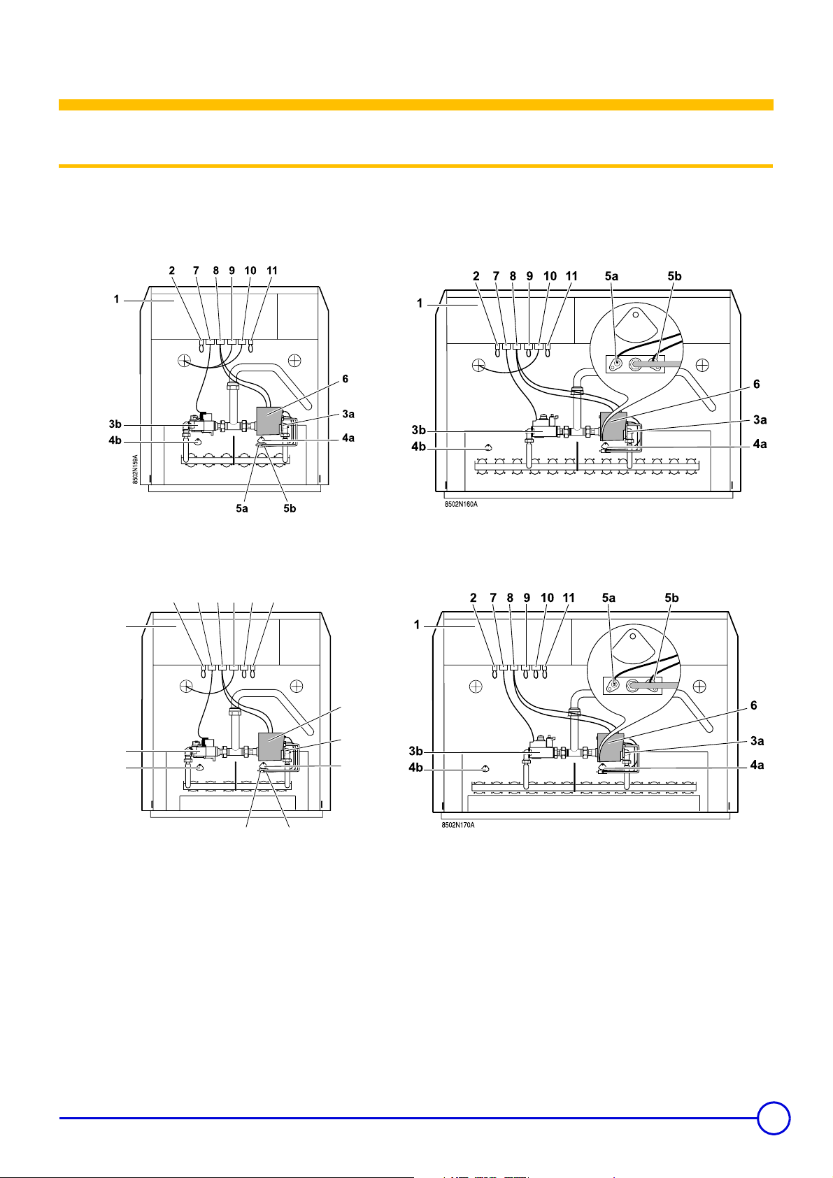
The models presented are marketed in the various countries according to the countries' specific sales programme.
DTG 230 Eco.NOx
6 to 13 sections 14 sections
3. Description
DTG 230 S
7 to 13 sections 14 sections
7 8 9 10 11
2
1
6
3b
4b
8502N169A
5a 5b
1. Control panel
2. Factory fitted bridge
Connection for gas pressure switch (Option - Package GC191)
Natural gas: 12.5 mbar
Propane: 20 mbar
3. a: Gas valve - Stage1
b: Gas valve - Stage2
4. a: Flame inspection window - Stage1
b: Flame inspection window - Stage2
5. a: Ignition electrode
b: Ionization probe
6. Safety box
7. Valve connector - Stage2
8. Safety control box and valve connector - Stage1
3a
4a
9. Downdraught thermostat
6-9 sections: Supplied
10-14 sections: Option (Factory fitted bridge) - Package GC22
Belgium + Russia: The downdraught thermostat is
compusory for all models of boiler and must be fitted
systematically.
10. DTG 230 Eco.NOx: Flue damper
DTG 230 S: Not used (Factory fitted bridge)
11. Factory fitted bridge
- Connection for cyclical tightness controller (Option - Package
CY41)
or
- Connection for safety valve (Option - Package GC191)
09/03/2011 - 300011506-001-D DTG 230
5
Page 6
3. Description
3.2 Control panel
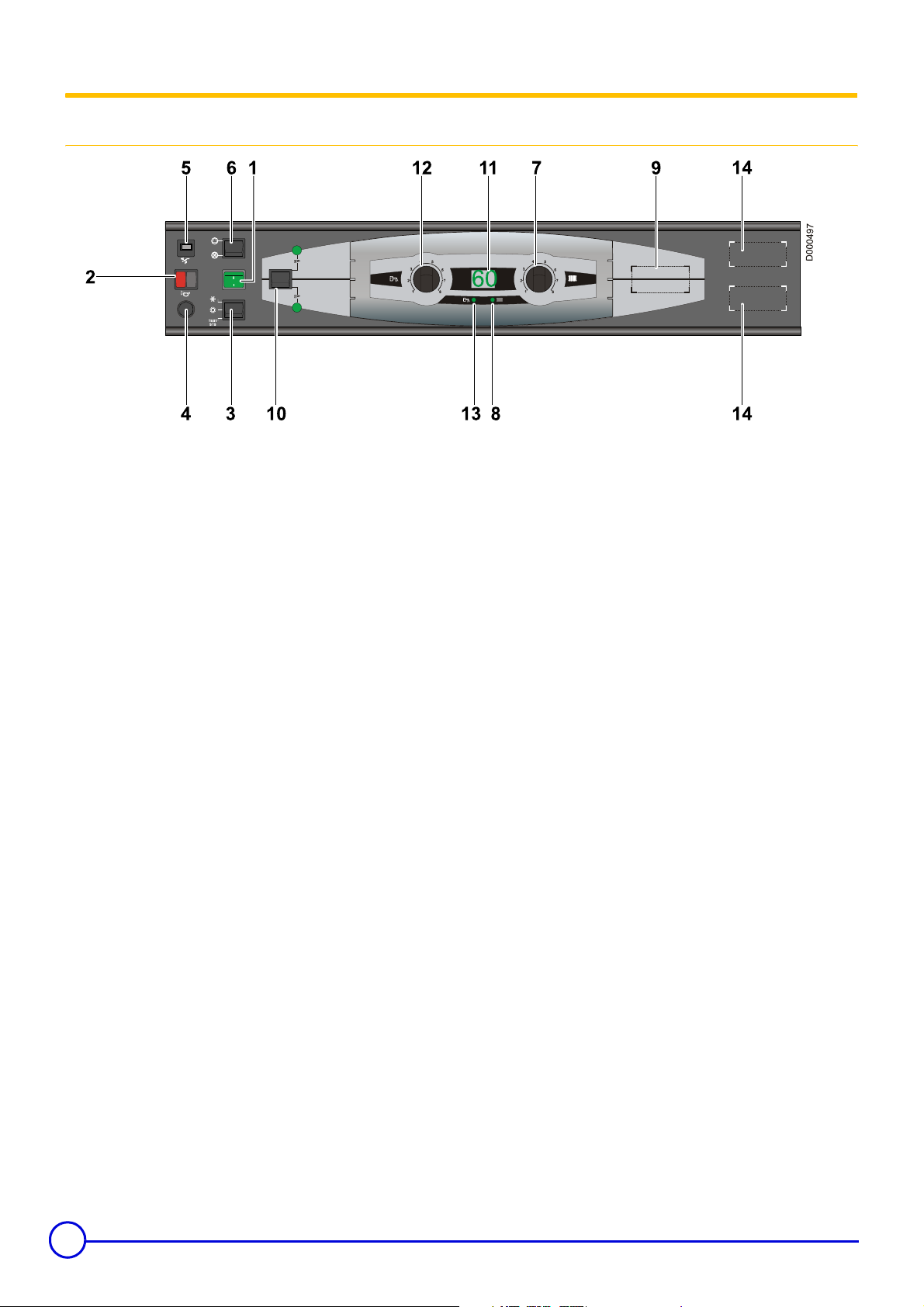
3.2.1 B3 control panel
1. General ON (1) / OFF (0) switch
2. Burner alarm indicator + Reset button
This light comes on when the safety control box is in safety
lockout (out of order).
3. Switch TEST-STB/
: Heating and domestic hot water are in operation
.
: Only domestic hot water is in operation
%
Position TEST-STB: Temporary action to test the safety
thermostat
4. Safety thermostat with manual reset
Set at 110° C
5. Timed circuit breaker (4 A)
6. Pump shutdown switch
7. Electronic thermostat (30 to 90 °C)
8. Heating on light
9. Location for flue gas thermometer (optional)
10. Switch for selecting the number of burner stages
(2-stage boilers)
11. Digital display
-Light 8 lit: Boiler temperature display
-Light
13
lit: Domestic hot water display
./%
When preparing domestic hot water
12. Electronic thermostat (10 to 80 °C)
13. Domestic hot water on light
14. Location for hour run meter (Option)
6
DTG 230 09/03/2011 - 300011506-001-D
Page 7

3.2.2 DIEMATIC-m3 control panel
Electromechanical components
3. Description
1. General ON (1) / OFF (0) switch
2. Burner alarm indicator + Reset button
This light comes on when the safety control box is in safety
lockout (out of order).
3. Switch AUTO/
/TEST-STB
!
AUTO: Automatic control
: Manual control
!
TEST-STB: Temporary action to test the safety thermostat
4. Safety thermostat with manual reset
Set at 110° C
5. Timed circuit breaker (4 A)
Display
3 4 5 6
2
024681012141618202224
1
1 Text and numerical display
2 Graphic display bar for the programme in circuit A, B or C
Light area: Reduced temperature heating period or tank load
3
disabled
Dark area: Comfort temperature heating period or tank load
4
enabled
5 Flashing cursor showing the current time
Number display (current time, adjusted values, parameters,
6
etc.)
7 Number of the boiler for which the parameters are displayed
The arrows flash when setting values can be modified using
8
the + and - keys
9 Circuit operation symbols
Opening the 3-way valve
>
Closing the 3-way valve
=
SUNDAY
6. Pump shutdown switch
7. Boiler thermostat (30 to 90 °C)
8. Boiler thermometer
9. Switch for selecting the number of burner stages
(2-stage boilers)
10. Connector USB
14. Boiler heat curve
15. Flap
16. Display
7
8
A
BC
91011
Arrows indicating the chosen time programme (P1, P2, P3 or
10
P4) for the circuit displayed, A, B, C, or the activation of the
manual summer mode
Symbols indicating that the following inputs/outputs are
11
active
DHW load pump on
Summer mode (Automatic / Manual)
#
Burner on
D
` Operation with modulating burner
Not used
` Operation with 2-stage burner
D Burner on with 1 stage
Burner on with 2 stages
Y
Displayed circuit pump on
:
A B C Name of the circuit displayed
09/03/2011 - 300011506-001-D DTG 230
7
Page 8

3. Description
3.2.3 K3 control panel
1. General ON (1) / OFF (0) switch
2. Burner alarm indicator + Reset button
This light comes on when the safety control box is in safety
lockout (out of order).
3. Switch AUTO/
AUTO: This position enables automatic operation of the
installation in accordance with DIEMATIC-m 3 regulation
controls.
: The boiler no longer takes orders from the DIEMATIC-m 3
!
regulation into account. The boiler is regulated by the boiler
thermostat(s).
TEST-STB: Temporary action to test the safety thermostat
/TEST-STB
!
4. Safety thermostat with manual reset
Set at 110° C
5. Timed circuit breaker (4 A)
6. Pump shutdown switch
7. Boiler thermostat (30 to 90 °C)
8. Boiler thermometer
9. Switch for selecting the number of burner stages
(2-stage boilers)
10. Connector USB
8
DTG 230 09/03/2011 - 300011506-001-D
Page 9

4 Operating the appliance
4.1 Commissioning the boiler
4. Operating the appliance
Initial commissioning must be done by a qualified
professional.
1. Check the water pressure in the installation. Top up with more
water if necessary.
2. Open the gas valve.
3. Make the settings on the control panel:
` B3 control panel:
- Turn the switch
- Turn the pump shutdown switch to
- Set the boiler thermostat to the desired setting.
- When preparing domestic hot water: Set the DHW thermostat to
the desired setting. Setting 6 (approx 60) recommended.
` DIEMATIC-m3 control panel:
- Turn the
- Turn the pump shutdown switch to
- Set the boiler thermostat to maximum (between 7½ and 9).
TEST-STB/./% to ..
AUTO / ! / TEST STB
9
switch to
9
AUTO
.
4.2 Changing the settings
` K3 control panel (Secondary boiler in cascade with a
DIEMATIC-m3 boiler):
-Set switch
4. Turn the burner switch to 2 (2 stage version)
5. Check that the safety thermostat has not triggered. Remove the
safety thermostat hood and press the reset button with a
screwdriver.
6. Set the On/Off switch to 1.
Only for control panel DIEMATIC-m3:
When the boiler is switched on, the tank exchanger is purged
for one minute if a tank is connected and its temperature is
lower than 25°C.
If disgassing has already taken place, press the MODE key to
suspend disgassing.
Only for control panel DIEMATIC-m3:
On commissioning, it is necessary to select the desired
language with the + and - keys and confirm with the MODE key.
AUTO
/ ! /
TEST STB
to the
AUTO
position.
4.2.1 B3 control panel
Heating temperature setting: Set the boiler thermostat to the
desired setting.
Setting the domestic hot water temperature: Set the DHW
thermostat to the desired setting.
09/03/2011 - 300011506-001-D DTG 230
9
Page 10

4. Operating the appliance
4.2.2 DIEMATIC-m3 control panel
Keys accessible when the flap is closed Keys accessible when the flap is open
Adjustment keys
MODE Various operating modes can be selected by successively
pressing key MODE:
` AUTOMATIQUE
` DAY 7/7: Forced operation at permanent Day temperature
` DAY (Until midnight): Forced operation at temporary Day
temperature
` NIGHT 7/7: Forced operation at permanent Night
temperature
` NIGHT (Until midnight): Forced operation at temporary
Night temperature
` DAYS ANTIFREEZ: Antifreeze mode for the number of
days set
` ANTIFREEZ 7/7: Permanent antifreeze mode
Restart key for a DHW calorifier load
` AUTOMATIQUE
` DHW: Restarts DHW load until midnight
` DHW 7/7: DHW load is forced permanently
After a few seconds, the display disappears but the mode is
activated.
Display key for the various counters (number of burner start-ups,
+
number of burner operating hours, etc.)
Adjustment keys
%O
$P
STANDARD
S
J
I
*
#
K
M
Enter (per 1/2 hour) the comfort temperature period or
tank load enabled (dark area).
Enter (per 1/2 hour) the reduced temperature period or
tank load disabled (light area).
Simultaneously pressing the 2 keys,
, resets all of the time programmes.
$P
Return key
Page scrolling
Line scrolling
Scroll of boilers connected
Manual "Summer" shutdown key. The heating is
switched off and DHW production is ensured.
Fitter settings access key
DO NOT USE
%O
and
Set temperatures Day (Heating / DHW / Pool)
2%
Set temperatures Night (Heating / DHW)
2$
Access key to the secondary boilers (Control panel K3) in a
cascade
*
If using only one boiler, this key is inactive.
Setting the gradients for circuits A, B and C
(
Setting the parallel offsets DECAL.// DEP.A, DECAL.// DEP.B or
DECAL.// DEP.C for the heating curves on circuits A, B or C.
)
If the Day setting for one of the circuits, A, B or C, is above 30°C,
you no longer have access parallel offset on this circuit.
Adjustment keys
+/-
4.2.3 K3 control panel
Heating temperature setting: Set the boiler thermostat to the
desired setting.
Make all other settings on the master boiler fitted with a DIEMATIC-
m3 control panel
Press the
*
key.
10
DTG 230 09/03/2011 - 300011506-001-D
Page 11

4.3 Switching off the boiler
4. Operating the appliance
Set the On/Off switch to 0.
DIEMATIC-m3 control panel
The panel must always be supplied with 230V voltage:
- to ensure the anti-grip of the heating pump,
- to ensure Titan Active System® operation when a titanium anode
is protecting the DHW tank.
Use the mode:
- summer to shut down the heating.
- antifreeze to shut down the boiler if you are to be absent.
4.3.1 Precautions to take if there is a danger of frost
Heating circuit:
Use a correctly dosed antifreeze to prevent the heating water
freezing. If this cannot be done, drain the system completely. In all
cases, consult the fitter.
Domestic hot water circuit:
Drain the domestic water tank and pipes.
4.3.2 Precautions to take in the event of prolonged shutdown (one year or more)
- Close the gas valve
- The boiler and the chimney must be swept carefully.
- Close the door of the boiler to prevent the internal circulation of air.
09/03/2011 - 300011506-001-D DTG 230
11
Page 12

5. Checking and maintenance
5 Checking and maintenance
Make the following checks at least 1 time a year:
- Checking the ignition burner
- Safety devices
- Water level
- Checking burner safety
- Checking the safety thermostat
- Checking the downdraught thermostat
6 Troubleshooting
6.1 Data plate
Before informing the fitter of a fault, make a note of the following
information:
Type of gas used
Boiler type
Manufacturing date
Year (01 = 2001, 02 = 2002, ...)
Week
Serial no. of the appliance
This information can be found on the rating plate stuck to the
front plate of the boiler.
Carry out the following maintenance at least 1 time a year:
- Cleaning main burner and ignition burner
- Cleaning of the heating body
- Cleaning painted surfaces
XX-XX
12
DTG 230 09/03/2011 - 300011506-001-D
Page 13

6.2 Error messages
6.2.1 B3 control panel
Message Faults Probable causes Action
AL 50 Boiler sensor
AL 52 Domestic hot water sensor The sensor is cut
AL td
Titanium anode
AL tc
The sensor circuit has been broken or
short circuited.
The titanium anode is in open circuit or
the tank is empty.
A short circuit has occurred on the
titanium anode or connection
reversed.
6.2.2 DIEMATIC-m3 control panel
Message Probable causes Action
SHOW REM. CTRL
REVISION Boiler service required. Advise the installer.
DISGAS
AUX1.SENS.FAIL
AUX2.SENS.FAIL
UNIV.SENS.FAIL
DHW 2 S. FAIL
BOILER S.FAIL.
OUTSI. S.FAIL.
DHW S. FAILURE
OUTL S.A FAIL.
OUTL S.B FAIL.
OUTL S.C FAIL.
ROOM S.A FAIL.
ROOM S.B FAIL.
ROOM S.C FAIL.
SMOKE S. FAIL.
SWIM.P.A S.FAIL
SWIM.P.B. S.FAIL
SWIM.P.C. S.FAIL
SOLAR S. FAIL
ST.TANK S.FAIL
The message SHOW REM.CTRL indicates the
presence of an override on a remote control.
When connecting voltage, if the hot water tank
temperature is below 25 ºC, the boiler carries out a
domestic water exchanger purge cycle.
The sensor circuit has been broken or short
circuited.
The sensor circuit has been broken or short
circuited.
The sensor circuit has been broken or short
circuited.
The sensor circuit has been broken or short
circuited.
The sensor circuit has been broken or short
circuited.
The sensor circuit has been broken or short
circuited.
The sensor circuit has been broken or short
circuited.
The sensor circuit has been broken or short
circuited.
The sensor circuit has been broken or short
circuited.
The sensor circuit has been broken or short
circuited.
To cancel the overrides on all remote controls, press the AUTO key for 5
seconds.
Wait 1 minute.
Advise the installer.
If the boiler sensor fails, the burner is controlled by the boiler thermostat and
the heating and DHW circuits operate normally.
Advise the installer.
The boiler setting is equal to BOILER MAX. but can be limited by the boiler
thermostat to a lower value.
- The valve setting is no longer ensured but monitoring the maximum
temperature of the circuit after the valve is ensured.
- Valves may be manually operated.
- Reheating the domestic hot water remains ensured.
Advise the installer.
To ensure domestic hot water production, set the switch AUTO/
STB to
!
Advise the installer.
The circuit concerned goes from automatic to manual mode: The pump
operates.
Advise the installer.
The circuit concerned operates without any influence from the room sensor.
Advise the installer.
This failure has no impact on the operating modes.
Advise the installer.
Pool reheating is independent of its temperature.
Advise the installer.
Reheating domestic hot water using the solar panel is no longer ensured.
Advise the installer.
The hot water storage tank reheating operation is no longer assured.
Advise the installer.
The installation is stopped.
Advise the installer.
The installation continues to operate but domestic hot
water heating is no longer covered.
Advise the installer.
Production of domestic hot water is stopped. This may be
reactivated for 24 hours by disconnecting and
reconnecting the power supply to the boiler.
Advise the installer.
.
5. Checking and maintenance
/TEST-
!
09/03/2011 - 300011506-001-D DTG 230
13
Page 14

5. Checking and maintenance
Message Probable causes Action
Domestic hot water production is shut down and can be restarted using key
TA-S SHORT-CIR The Titan Active System® is short-circuited.
TA-S DISCONNEC The Titan Active System® is on an open circuit.
TA-S FAILURE Internal problem.
The last ten failures are memorised in the paragraph #DEF.
HISTORY
. The tank is no longer protected.
Advise the installer.
Domestic hot water production is shut down and can be restarted using key
. The tank is no longer protected.
Advise the installer.
Switch off the current.
Advise the installer.
6.2.3 K3 control panel
No error messages displayed. See DIEMATIC-m3 control panel
display.
6.3 Incidents and solutions
The burner is not working:
- Check the boiler thermostat settings.
- Shutdown by the safety thermostat due to accidental overheating
Check that the safety thermostat has not triggered. To restart the
boiler, reset the safety thermostat. Remove the safety thermostat
hood and press the reset button with a screwdriver. Carry out the
start-up operations again. Call your fitter.
- Check the circuit breaker
- The safety control box is malfunctioning (Fault indicator light
illuminated)
Press the resetting button of the burner. Call your fitter.
The burner is operating but the radiators are cold:
- Bleed the radiators.
- Top up the primary circuit with water.
If it is often necessary to top up the installation with water, contact
your fitter.
- Check that the heating pump is operating correctly.
- Check the position of the 3 position switch.
B3 control panel: TEST-STB/
DIEMATIC-m3 control panel: AUTO/
K3 control panel: AUTO/
- Check the boiler thermostat settings.
/TEST STB on AUTO
!
./%
on ..
/TEST STB on AUTO.
!
14
DTG 230 09/03/2011 - 300011506-001-D
Page 15

7 Technical characteristics
7. Technical characteristics
DTG 230-... Eco.NOx / S
Useful output
Smoke temperature
Minimum output temperature°C 303030303030303030
Maximum output temperature°C 909090909090909090
Maximum operating pressurebar666666666
Electrical connection V/Hz 230/50 230/50 230/50 230/50 230/50 230/50 230/50 230/50 230/50
Electrical power
(1) (3)
Gas connection inch R1R1R1R1R1R1R1R1R1
Heating connection inch R1 1/2 R1 1/2 R1 1/2 R1 1/2 R1 1/2 R1 1/2 R1 1/2 R1 1/2 R1 1/2
Internal diameter flue gas nozzle mm 150 160/180 180 180 200 200 200 220/225 220/225
Water content l 25 29 32.6 36.2 39.8 43.4 47 50.6 54.2
Net weight (without water) kg 203 230 257 283 305 334 357 386 408
(1) At nominal output (Stage2)
(2) Boiler temperature: 80 °C
(3) Electrical power of the boiler only with no accessories
Only in France:
(4)
Stage1 kW 27 27 36 36 45 45 54 54 54
Stage2 kW 45 54 63
(1) (2)
B3
DIEMATIC-m3K3W
°C 135 135 135 135 135 135 135 135 135
A useful output lower than 70 kW makes it possible to install
the boiler in a mini-boiler room.
(5) Only Eco.NOx version
(5)
6
20
21
19
7 8 9 10 11 12 13 14
20
21
19
20
21
19
69.9
20
21
19
(4)
/72
81 90 99 108 117
20
21
19
20
21
19
20
21
19
20
21
19
20
21
19
Conditions of use:
- Max. safety temperature: 110 °C
- Max. operating pressure: 6 bar
- Thermostat adjustable from 30 to 90°C
- Safety thermostat: 110 °C
8 Energy savings
Here are a few tips for saving energy:
- Install reflector panels behind the radiators.
- Do not cover the radiators. Do not hang curtains in front of the
radiators.
- Insulate pipes to prevent thermal losses and condensation.
- Do not obstruct aeration grates (even partially). They help to
reduce humidity in the home. The more humid a home, the more
heating it consumes.
- Turn heating off when airing a room (5 minutes a day is sufficient)
Avoid deregulating the thermostat. Switch the On/Off switch to Off.
- Do not shut down heating completely if you are absent. Lower the
thermostat by 3-4°C.
- Use the sun's heat as much as possible.
- Take showers rather than baths. Use a water-saving shower head.
09/03/2011 - 300011506-001-D DTG 230
15
Page 16

7. Technical characteristics
Warranty
You have just purchased one of our appliances and we thank you
for the trust you have placed in our products. Please note that your
appliance will provide good service for a longer period of time if it is
regularly checked and maintained. Your fitter and our customer
support network are at your disposal at all times.
Warranty terms
Starting from the purchase date shown on the original fitter's
invoice, your appliance has a contractual guarantee against any
manufacturing defect.
The length of the guarantee is mentioned in the price catalogue.
The manufacturer is not liable for any improper use of the appliance
or failure to maintain or install the unit correctly (the user shall take
care to ensure that the system is installed by a qualified fitter). In
particular, the manufacturer shall not be held responsible for any
damage, loss or injury caused by installations which do not comply
with the following:
- applicable local laws and regulations
- specific requirements relating to the installation, such as national
and/or local regulations
- the manufacturer's instructions, in particular those relating to the
regular maintenance of the unit
- the rules of the profession
The warranty is limited to the exchange or repair of such parts as
have been recognised to be faulty by our technical department and
does not cover labour, travel and carriage costs. The warranty shall
not apply to the replacement or repair of parts damaged by normal
wear and tear, negligence, repairs by unqualified parties, faulty or
insufficient monitoring and maintenance, faulty power supply or the
use of unsuitable fuel. Sub-assemblies such as motors, pumps,
electric valves etc. are guaranteed only if they have never been
dismantled.
Italy
The duration of our warranty is shown on the certificate delivered
with the appliance.
Our liability as manufacturer may not be invoked in respect of
incorrect use of the appliance, incorrect or insufficient maintenance
thereof, or incorrect installation of the appliance (you must
therefore ensure that installation and maintenance operations are
carried out respectively by a qualified professional and by an after
sales service company).
The legislation laid down by European Directive 99/44/EEC,
transposed by Legislative Decree No. 24 of 2 February 2002
published in O.J. No. 57 of 8 March 2002, continues to apply.
Russia
The foregoing provisions in no way affect the rights of the
consumer, which are guaranteed by the legislation of the Russian
Federation as regards hidden defects.
The terms and conditions of warranty and the terms and conditions
of application of the warranty are indicated on the warranty form.
The warranty shall not apply as regards the replacement or repair
of wearing parts under normal use. Such parts include
thermocouples, injection nozzles, flame control and ignition
systems, fuses and gaskets.
Turkey
Due to the laws and regulations the product life for this product is
10 years. During that time the producer and/or the distributor has
to provide after sales services and spare parts.
Other countries
The above provisions do not restrict the benefit of the legal laws
regarding hidden defects applicable in the buyer's country.
France
The preceding dispositions are not exclusive of benefits for the
purchaser of the legal guarantee as stated in Civil Code articles
1641 to 1648.
Poland
Warranty conditions are included in the warranty card.
Switzerland
The application of the warranty is subject to the terms and
conditions of sale, delivery and warranty of the company marketing
our products.
Belgium
The preceding dispositions about the contractual guarantee are not
exclusive of profit if the need arises for the purchaser in Belgium of
the applicable legal dispositions on hidden defects.
16
DTG 230 09/03/2011 - 300011506-001-D
Page 17

7. Technical characteristics
09/03/2011 - 300011506-001-D DTG 230
17
Page 18

Page 19

Page 20

FR
DE DIETRICH THERMIQUE S.A.S.
www.dedietrich-thermique.fr
Direction des Ventes France
57, rue de la Gare
F- 67580 MERTZWILLER
+33 (0)3 88 80 27 00
+33 (0)3 88 80 27 99
DE
BE
CN
DE DIETRICH REMEHA GmbH
www.dedietrich-remeha.de
Rheiner Strasse 151
D- 48282 EMSDETTEN
+49 (0)25 72 / 23-5
+49 (0)25 72 / 23-102
info@dedietrich.de
VAN MARCKE
www.vanmarcke.be
Weggevoerdenlaan 5
B- 8500 KORTRIJK
+32 (0)56/23 75 11
DE DIETRICH
www.dedietrich-heating.com
Room 512, Tower A, Kelun Building
12A Guanghua Rd, Chaoyang District
C-100020 BEIJING
+86 (0)106.581.4017
+86 (0)106.581.4018
+86 (0)106.581.7056
+86 (0)106.581.4019
contactBJ@dedietrich.com.cn
LU
RU
AT
NEUBERG S.A.
www.dedietrich-heating.com
39 rue Jacques Stas
L- 2010 LUXEMBOURG
+352 (0)2 401 401
DE DIETRICH
www.dedietrich-otoplenie.ru
129090 г. Москва
ул. Гиляровс кого, д. 8
офис 52
+7 495 988-43-04
+7 495 988-43-04
dedietrich@nnt.ru
ÖAG AG
www.oeag.at
Schemmerlstrasse 66-70
A-1110 WIEN
+43 (0)50406 - 61624
+43 (0)50406 - 61569
dedietrich@oeag.at
CH
WALTER MEIER (Klima Schweiz) AG
www.waltermeier.com
Bahnstrasse 24
CH-8603 SCHWERZENBACH
+41 (0) 44 806 44 24
Serviceline +41 (0)8 00 846 846
+41 (0) 44 806 44 25
ch.klima@waltermeier.com
WALTER MEIER (Climat Suisse) SA
www.waltermeier.com
Z.I. de la Veyre B, St-Légier
CH-1800 VEVEY 1
+41 (0) 21 943 02 22
Serviceline +41 (0)8 00 846 846
+41 (0) 21 943 02 33
ch.climat@waltermeier.com
© Copyright
All technical and technological information contained in these technical instructions, as well as any
drawings and technical descriptions supplied, remain our property and shall not be multiplied
without our prior consent in writing.
Subject to alterations.
09/03/2011
AD001NU-AC
DE DIETRICH THERMIQUE
57, rue de la Gare F- 67580 MERTZWILLER - BP 30
 Loading...