


972
Table of contents
 Loading...
© 1997, 1999, 2000, 2001 dCS
Ltd
All rights reserved. Reproduction of this manual in any manner whatsoever,
without the written permission of dCS
1
is strictly forbidden. Additional copies of
this manual may be obtained from dCS.
Information contained in this manual is subject to change without notice, and
whilst it is checked for accuracy, no liabilities can be accepted for errors.
1
dCS
Ltd is Data Conversion Systems Ltd. Company registered in the England no. 2072115
dCS 972
Digital to Digital Converter
User Manual
Software version 2.3x
January 2001

dCS 972 User Manual Manual for Software Version 2.3x
dCS Ltd January 2001
Manual part no: DOC1241102C2
Page 2
Document No: OS-MA-A0124-110.2C2
Contact
dCS
on + 44 1799 531 999 email to: more@dcsltd.co.uk
(inside the UK replace + 44 with 0) web site: www.dcsltd.co.uk

dCS 972 User Manual Manual for Software Version 2.3x
dCS Ltd January 2001
Manual part no: DOC1241102C2
Page 3
Document No: OS-MA-A0124-110.2C2
Contact
dCS
on + 44 1799 531 999 email to: more@dcsltd.co.uk
(inside the UK replace + 44 with 0) web site: www.dcsltd.co.uk
Product Features
Formats
DSD, and PCM from 192 kS/s down to 11.025 kS/s
PCM data formats supported are: AES/EBU (XLR), Dual AES (XLR), SPDIF
(Phono, Toslink and BNC) and SDIF-2
DSD data formats supported are SDIF-2 and SDIF-3
Converts double speed (88.2 & 96 kS/s) AES3, SPDIF or SDIF-2 into Dual (2
wire) AES3 and vice-versa.
Syncing
Comprehensive - can sync to Word Clock or AES reference, or signal, and sync
to video option available.
Functions
Sample Rate and Format Conversion
Multichannel Sync capability
Bit for bit multiplex/demultiplex mode
PCM to DSD, DSD to PCM
DC Removal for DSD
Multiple filters on many major sample rate conversions
Dither – 3 types
Noise shaping – 10 different options on all major PCM sample rates
Output Level control with “Maximise”
Balance control
Digital Silence out with digital silence in
Monitoring
Bit Activity, Stereo Level, and CRC, Parity & Invalid flag errors in the input data.
Test Generator
High quality (160 dB) signal generator with mHz resolution. Can be dithered
and/or noise shaped truncated.
Ease of Use
User programmable set-ups.
Pre-loaded setups
Remembers last settings
Lockouts

dCS 972 User Manual Manual for Software Version 2.3x
dCS Ltd January 2001
Manual part no: DOC1241102C2
Page 4
Document No: OS-MA-A0124-110.2C2
Contact
dCS
on + 44 1799 531 999 email to: more@dcsltd.co.uk
(inside the UK replace + 44 with 0) web site: www.dcsltd.co.uk
Contents
Product Features 3
About this Manual 5
Using Your dCS 972 For The First Time ............................................................6
Product Overview 6
What’s in the Box? 6
Mains Voltages 6
Installing Unit in a Rack 7
Getting Started 8
The Hardware – Controls and Connectors.....................................................10
Rear Panel 10
Digital Data Formats Supported 12
Front Panel 14
Navigating through the Menu – what the On Screen symbols mean 16
The Software – Menu and Setups ...................................................................18
Top Menu 20
Sample Rate Conversion / Format Conversion Submenu 24
Error Monitor Submenu 34
Test Submenu 35
Info Submenu 38
Bit Activity Monitor Submenu 38
Level Meters Submenu 39
Display Submenu 42
Setups and Locking the Front Panel 43
Typical Applications.........................................................................................46
Converting a 24/96 recording to CD format 46
Demultiplexing a 24/96 Dual AES recording (Bit for Bit) 47
Upsampling a CD 48
General Sample Rate Conversion and Distribution 49
PCM to DSD 50
Using a Master Clock 51
Multi-channel Sample Rate Conversion – bit aligned sources 52
Multi-channel Sample Rate Conversion – Using a Master Clock 53
Multi-channel Sample Rate Conversion – with more alignment tolerance 54
Multi-channel Sample Rate Conversion – with multiple sample rates out 55
dCS 972 Technical Information.........................................................................58
DSD 58
PCM input and/or Output Performance 60
Clocking 63
Sample Alignment 64
Multiple Channel Sync’ing 68
Multiple Channel Multiple Sample Rate Synchronising 70
Noise Shaping 71
Dither 72
Digital Interface Specifications 73
Message Handling 74
Power Consumption 77
Size, Weight and Operating Conditions 78
dCS 972 Performance Curves...........................................................................80
General Technical Information........................................................................90
Word Length Reduction 90
Options ..............................................................................................................96
Locking to Video Sample Rates 96
Mains Supply Voltage 96
Ordering Options for a New Unit 96
Having Your Options Changed 96

dCS 972 User Manual Manual for Software Version 2.3x
dCS Ltd January 2001
Manual part no: DOC1241102C2
Page 5
Document No: OS-MA-A0124-110.2C2
Contact
dCS
on + 44 1799 531 999 email to: more@dcsltd.co.uk
(inside the UK replace + 44 with 0) web site: www.dcsltd.co.uk
Maintenance and Support................................................................................98
Hardware 98
Software 99
Warranty 100
Update or Calibration 101
Safety and Electrical Safety 101
Troubleshooting .............................................................................................102
FAQs 102
If You Need More Help 105
Other Information 105
Indexes and Software Version Numbers......................................................106
Owner Registration Transfer 113
About this Manual
Note that there is a Full Contents at the end of the manual (page 107), along
with an index and lists of figures and tables.
References to other sections in the text have the Section Name, page … in
bold.
IMPORTANT!
Important information is presented like this - ignoring this may cause you to
damage the unit, or invalidate the warranty.
The manual is designed to be helpful. If there are points you feel we could cover
better, or that we have missed out - please tell us.

dCS 972 User Manual Manual for Software Version 2.3x
dCS Ltd January 2001
Manual part no: DOC1241102C2
Page 6
Document No: OS-MA-A0124-110.2C2
Contact
dCS
on + 44 1799 531 999 email to: more@dcsltd.co.uk
(inside the UK replace + 44 with 0) web site: www.dcsltd.co.uk
U
SING
Y
OUR
dCS 972
F
OR
T
HE
F
IRST
T
IME
Product Overview
The dCS 972 DDC (Digital to Digital Converter) is a high performance real time
sample rate and format converter. It is designed for studio applications where
source material is available in one format, but outputs are required in other
digital formats in real time. For example, archives might be made for storage in
24/192 or 24/176.4 formats, and then used to produce output in SACD, DVD,
CD and other multimedia formats. AES3, SPDIF, SDIF-2 and DSD formats are
all supported, and multiple units may be synchronised for stable multi-channel
operation.
The unit is mains powered and is housed in a 2U (3.5”) high 19” rack mounting
case. It may be controlled either from its front panel, or from a software based
remote control running on a PC. Frequently used Setups may be stored and re-
called later. The last setting is automatically stored on power down, so that fixed
installations may be set up at leisure, installed and then left alone. Unauthorised
alterations to settings may be prevented by a “panel lock out” feature.
Numerous monitoring functions are provided – both for the audio signal and for
messaging attached to it. The unit has bit activity and level meters, and
message manipulation. CRC, parity and invalid errors may be monitored and
reported, so that “right first time” transfer to disc plants may easily be achieved.
The unit is highly software based, and more functions and features are added
from time to time. Software updates from dCS are free!
2
What’s in the Box?
The contents of the box are at least:
dCS 972
User Manual
Quick Start Guide
Mains Lead
2 Spare Fuses
Remote cable
Remote software
Mains Voltages
The dCS 972 is shipped with its mains voltage preset for operation in the
destination country. The voltage is not intended to be changed by the user. If it
needs to be changed, see the section Having Your Options Changed on page
96.
2
free if we email them, and you download from a PC COM port. Low cost if you ask us for EPROMs or other
media - we charge for media and handling.

dCS 972 User Manual Manual for Software Version 2.3x
dCS Ltd January 2001
Manual part no: DOC1241102C2
Page 7
Document No: OS-MA-A0124-110.2C2
Contact
dCS
on + 44 1799 531 999 email to: more@dcsltd.co.uk
(inside the UK replace + 44 with 0) web site: www.dcsltd.co.uk
Installing Unit in a Rack
The unit is supplied with 19" rack mount ears fitted. If it is to be installed in a 19"
rack, the ears supplied may be used to locate it in the rack - but:
IMPORTANT!
The ears should not be used as the only mechanical support. The unit should
rest on a shelf, or be supported in some other way. The ears will just locate
it in the rack, and stop it sliding forwards.
If the unit is not to be rack mounted, the ears may be removed.
dCS 972 User Manual Manual for Software Version 2.3x
dCS Ltd January 2001
Manual part no: DOC1241102C2
Page 8
Document No: OS-MA-A0124-110.2C2
Contact
dCS
on + 44 1799 531 999 email to: more@dcsltd.co.uk
(inside the UK replace + 44 with 0) web site: www.dcsltd.co.uk
Getting Started
Here’s what to do:
(If the unit does not behave the first time you power up – contact your dealer, or
dCS.)
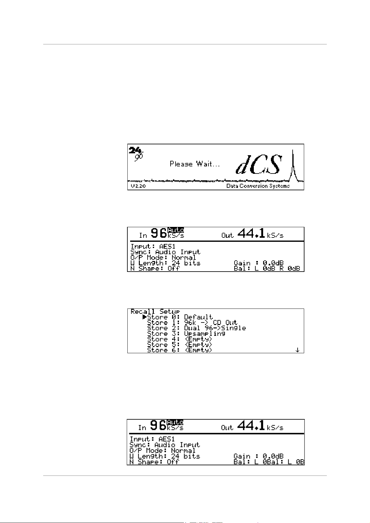
do this: Check the appropriate mains supply for your local mains is marked on the rear
panel.
do this: If it is, using the lead supplied, connect the unit to the mains - connect no other
leads at this stage - and switch on. The Power LED will light, then the screen
will light up and display:
After approximately 15 seconds, the front panel LEDs will indicate the last stored
state and the Unlocked LED will light. The screen will then display the Status
Screen, for example:
do this: Connect a signal source to an appropriate input: AES 1 or 2, SPDIF1, 2 or 3 or
SDIF-2 CH1, CH2 & CLK – we recommend an AES3 source into AES 1 until
you are happy with the unit.
do this: Press the Recall button. The display will change to:
do this: Select Store 0 (the default setting) with the rotary knob and press the Enter
button.
A message window will appear in the display to confirm that the unit is reading
the setup. Then, when complete, the message will go away, the unit will lock
and the Unlocked LED will go out. The display then shows the status screen for
the default setup as below if you have a 96 kS/s source connected to AES 1 –
otherwise the left hand number will adjust to what you have connected.

dCS 972 User Manual Manual for Software Version 2.3x
dCS Ltd January 2001
Manual part no: DOC1241102C2
Page 9
Document No: OS-MA-A0124-110.2C2
Contact
dCS
on + 44 1799 531 999 email to: more@dcsltd.co.uk
(inside the UK replace + 44 with 0) web site: www.dcsltd.co.uk
The (converted) input signal will now be available at all of the outputs. Connect
the output of your choice to the input of a 44.1 kS/s recorder, DAC or other
equipment you wish to drive. It will now lock to the dCS 972.
Note that all the outputs are active when the dCS 972 is locked. They may all be
connected to external equipment simultaneously if required. Similarly, all of the
inputs may be connected as the active one will be selected by the Audio Input
Select menu.
Now you will need to familiarise yourself with how the control software and menu
system work.
do this: Read the short section on Navigating through the Menu – what the On
Screen symbols mean, page 16 so you know how the buttons and cursor work.
You may also find it convenient to refer to the Quick Start Guide while you are
getting to know the unit.
dCS 972 User Manual Manual for Software Version 2.3x
dCS Ltd January 2001
Manual part no: DOC1241102C2
Page 10
Document No: OS-MA-A0124-110.2C2
Contact
dCS
on + 44 1799 531 999 email to: more@dcsltd.co.uk
(inside the UK replace + 44 with 0) web site: www.dcsltd.co.uk
T
HE
H
ARDWARE
– C
ONTROLS AND
C
ONNECTORS
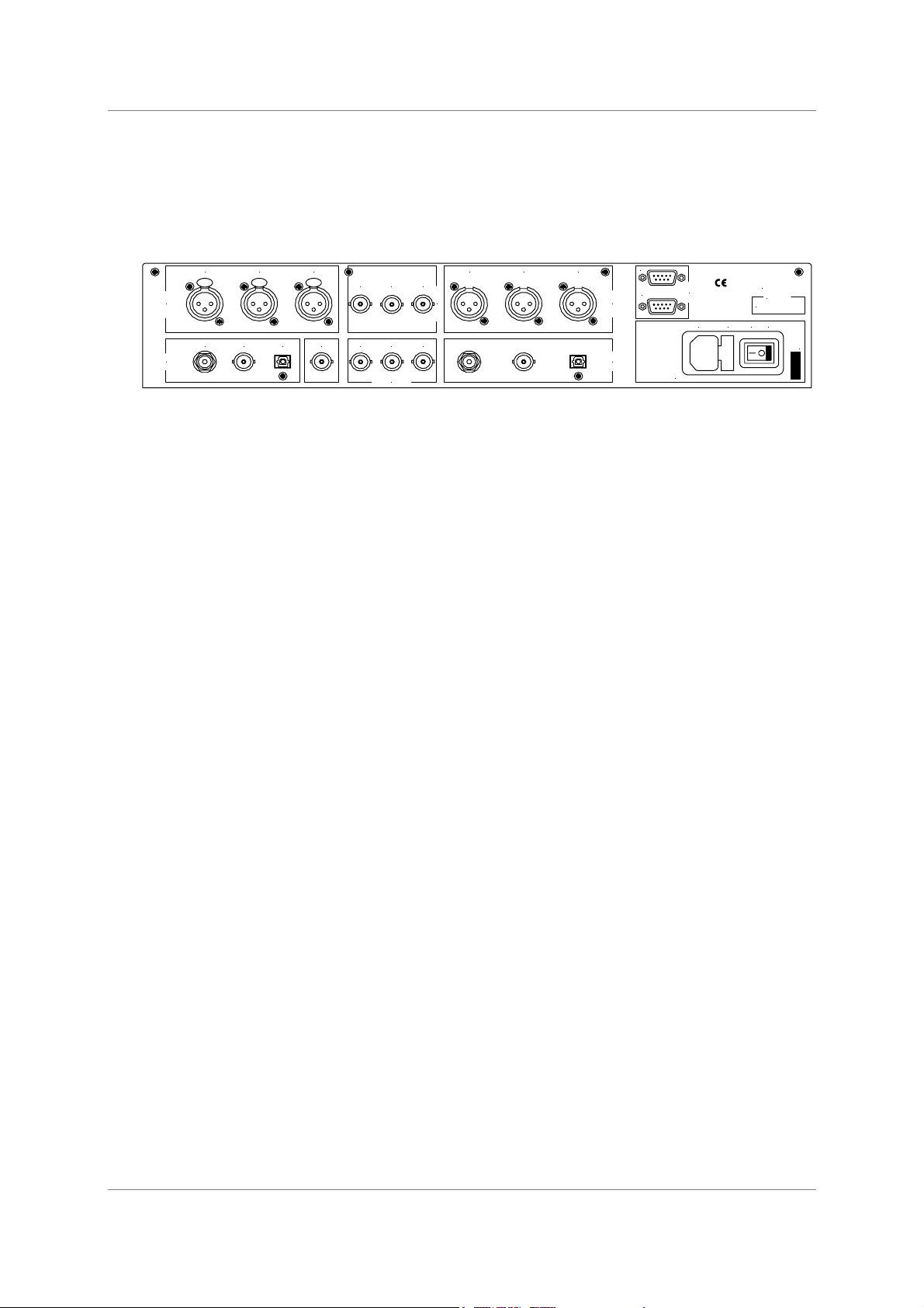
Rear Panel
PUSH PUS H PUS H
AES1 AES2 AES CLK
CH1 CH2 CLK
AES1 AES2 AES CLK
SPDIF1 SPDIF2 SPDIF3 SYNC IN CH1 CH2 CL K
AES / EBU
Inputs
SPDIF
Inputs
SDIF-2 Inputs
SDIF-2 Outputs
AES / EBU
Outputs
SPDIF
Outputs
MAINS FUSE 2A(T) ON OFF
Remote
In
Out
Disconnect mains
before removing cover.
See User Manual for
installation instructions
before connecting supply.
V 50-60Hz
more@dcsltd.co.uk
dCS 972
See base for
serial num ber
Figure 1– Rear Panel
All input and output connectors are mounted on the rear panel. Individual
connectors are clearly identified by the panel legend. Viewed from the rear from
left to right and top row first, the connectors are as follows:
Signal Inputs
AES/EBU Digital Inputs 3 pin XLR Female (3 off – AES 1, AES 2, AES CLK)
Used for AES3 format signals. AES 2 is used in Dual AES mode while AES CLK
is used for AES3 references and also for Sync Link operation in multi-channel
synchronising.
SDIF Inputs BNC (3 off – CH1, CH2, Wordclock In)
Used as a set for SDIF-2 (PCM or DSD), or CH1, CH2 used for SDIF-3 (DSD
only). Wordclock In may also be used for a 10 MHz GPS reference
SPDIF Inputs Various (3 off - RCA Phono, BNC, Toslink optical)
Used for SPDIF inputs. SPDIF1 is the RCA, SPDIF2 is the BNC, SPDIF3 is the
Toslink optical input.
Sync Input BNC
This is intended for future enhancements.

dCS 972 User Manual Manual for Software Version 2.3x
dCS Ltd January 2001
Manual part no: DOC1241102C2
Page 11
Document No: OS-MA-A0124-110.2C2
Contact
dCS
on + 44 1799 531 999 email to: more@dcsltd.co.uk
(inside the UK replace + 44 with 0) web site: www.dcsltd.co.uk
Signal Outputs
AES/EBU Digital Outputs 3 pin XLR Male (3 off – AES A, AES B, AES CLK)
Used for AES3 format signals, including Dual AES mode. In single AES modes,
AES B and AES CLK follow AES A. In Dual AES modes, AES A and AES B
are used. AES CLK is used for Sync Link operation in multi-channel
applications.
SDIF Outputs BNC (3 off – CH1, CH2, Wordclock Out)
Used as a set for SDIF-2 (PCM or DSD) or CH1, CH2 used for SDIF-3 (DSD
only) outputs
SPDIF Outputs Various (3 off - RCA Phono, BNC, Toslink optical)
Used for SPDIF outputs. SPDIF1 is the RCA, SPDIF2 is the BNC, SPDIF3 is
the Toslink optical output.
Control and Power
Remote 9 pin D type Female (2 off, In and Out)
For remote control via a PC, and/or downloading software updates. Remote In
and Out sockets allow daisy chaining of several different dCS units from one
COM port.
Mains Supply 3 pin IEC (CEE22)
Switched, fused and filtered IEC mains connector, for 50 or 60 Hz mains
Additional Information
As well as connectors, the rear panel displays the following information about
the unit, near the mains supply connector:
Mains Voltage The actual voltage setting supplied.
Model Number dCS 972
Manufacturers Name and Country of origin (dCS Ltd, UK)
The underside of the unit will have a label on that contains a number such as
972 4B1 6B2 2A1 3A2 12345. This is the serial number, but it also contains vital
configuration information. We will need this number (all of it) to give you support
over the phone, or to ship you software updates.

dCS 972 User Manual Manual for Software Version 2.3x
dCS Ltd January 2001
Manual part no: DOC1241102C2
Page 12
Document No: OS-MA-A0124-110.2C2
Contact
dCS
on + 44 1799 531 999 email to: more@dcsltd.co.uk
(inside the UK replace + 44 with 0) web site: www.dcsltd.co.uk
Digital Data Formats Supported
The unit provides six digital data i/o formats,
AES/EBU (often referred to as AES3) for PCM operation
Dual AES (part of the AES3 spec) for PCM operation
SDIF-2 for PCM operation
SDIF-2 for DSD operation
SDIF-3 for DSD operation
SPDIF (electrical) for PCM operation
SPDIF (optical) for PCM operation
For all formats, the incoming Channel Status and User messages are
discarded
3
. The unit allows the AES/EBU and SPDIF output Channel Status bits
to be edited.
The enhanced AES/EBU interface is fully implemented. Each channel has its
own parity and data validity bit, as well as User and Channel Status messages.
Cyclic Redundancy Counts (CRC's) are generated from the Channel Status
message. The Dual AES interface allows a 96 or 88.2 kS/s 24 bit signal to be
coded as two standard 48 or 44.1 kS/s 24 bit AES data streams, recorded as
two channels on a recorder with standard capacity, replayed and decoded back
into a single data stream. Operation of the Dual AES interface at double speed
allows the unit to input or output 2 wire 192 kS/s 24 bit data, and convert to and
from this.
SDIF-2 PCM message bits are internally set to zero, with the exception of the
block code, which is implemented.
The SPDIF interface has no CRC's - as per definition. Data formats for both
SPDIF electrical and SPDIF optical are identical.
DSD has, at the time of writing, no messaging structure. Contact dCS for more
details. Data formats use either the SDIF-2 system (two data channels and third
clock channel) or the SDIF-3 format (two data channels with embedded clock).
3
At present we do this because there is no standard on what to do with the excess or shortage of bits that is
created by a sample rate change. If this causes you a problem, call us – we can probably do something else,
if we are clear what that ought to be.

dCS 972 User Manual Manual for Software Version 2.3x
dCS Ltd January 2001
Manual part no: DOC1241102C2
Page 13
Document No: OS-MA-A0124-110.2C2
Contact
dCS
on + 44 1799 531 999 email to: more@dcsltd.co.uk
(inside the UK replace + 44 with 0) web site: www.dcsltd.co.uk
dCS 972 User Manual Manual for Software Version 2.3x
dCS Ltd January 2001
Manual part no: DOC1241102C2
Page 14
Document No: OS-MA-A0124-110.2C2
Contact
dCS
on + 44 1799 531 999 email to: more@dcsltd.co.uk
(inside the UK replace + 44 with 0) web site: www.dcsltd.co.uk
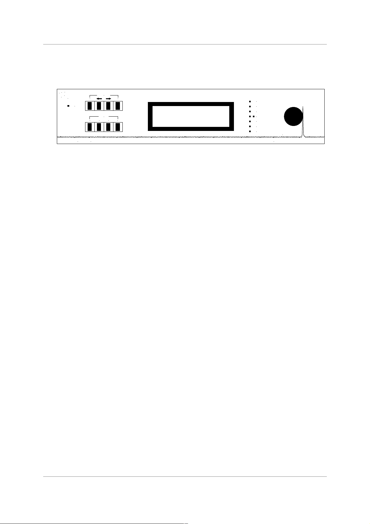
Front Panel
Recall Edit Store Enter
Status Set
OPERATION
MEMORY
Power
D to D Converter
dCS 972
Phase
Gain
Balance
Unlocked
Dither
Noise shaping
L/R flip
Data Conversion Systems
2
4
9
6
dC S
BIT
kHz
Figure 2 – Front Panel
Because of the many options on the dCS 972, we have used a menu based
system to control it. The hardware buttons and knobs below navigate you
through it.
OPERATION buttons
The bank of 4 buttons in the top left hand corner are the Operation buttons and
are used for navigating around the menu tree:
Status returns the display to the status information screen
to allow a rapid check of key settings.
←
←←
←
selects the previous (higher) menu level.
→
→→
→ selects the next (lower) menu level.
Set implements the selected menu item.
MEMORY buttons
The bank of 4 buttons in the lower left hand corner are the Memory buttons and
are used for storing and retrieving setups:
Recall allows one of ten stored setups to be selected
ready for loading.
Store allows one of ten locations to be selected as the
location for saving the current setup.
Edit is used to change the name of a saved setup.
Enter loads or saves a setup.
LCD display
The backlit LCD display in the centre of the panel can display up to 8 lines of
information.

dCS 972 User Manual Manual for Software Version 2.3x
dCS Ltd January 2001
Manual part no: DOC1241102C2
Page 15
Document No: OS-MA-A0124-110.2C2
Contact
dCS
on + 44 1799 531 999 email to: more@dcsltd.co.uk
(inside the UK replace + 44 with 0) web site: www.dcsltd.co.uk
LED indicators
A group of LED indicators to the right of the LCD display gives a level of status
indication:
Dither is lit if any Dither is selected.
Noise shaping is lit if any Noise Shaping is selected.
L/R flip indicates that the channels are flipped.
Two Phase LEDs indicate if either or both channels are phase
inverted.
Gain is lit if the setting is other than unity gain (i.e. 0dB).
Balance is lit if the channel balance is shifted from centre.
Unlocked is lit if the unit is not locked to a valid digital input.
Rotary encoder
Turn the knob to move up down the menu tree, adjust parameter values or edit
store names. The user may select whether clockwise rotation moves the cursor
up or down - see the section on Display Customise, page 32. The unit is
shipped with the cursor moving downwards by clockwise rotation of the knob
and all instructions in this manual refer to a unit in this configuration. We
recommend turning the knob at a steady speed, rather than trying to turn it as
fast as possible.
Power LED
The LED in the top left hand corner lights when power is applied.
dCS 972 User Manual Manual for Software Version 2.3x
dCS Ltd January 2001
Manual part no: DOC1241102C2
Page 16
Document No: OS-MA-A0124-110.2C2
Contact
dCS
on + 44 1799 531 999 email to: more@dcsltd.co.uk
(inside the UK replace + 44 with 0) web site: www.dcsltd.co.uk
Navigating through the Menu – what the On Screen symbols mean
Once the unit has powered up and the Status screen is displayed, you can start
navigating through the menu. This section explains how the keys operate, and
what the various on screen indications mean. To start, pressing either the ←
←←
← or
→
→→
→ button brings up the top level of the Menu:
The symbol is the cursor and an indication that there are sub-menus
available below this level. If there are no more submenus, it changes to
. Turn
the rotary control clockwise and the cursor will move down the list. Turn the
rotary control counter clockwise and the cursor will move back up. To access
the Sample Rate Conversion menu, set the cursor adjacent to Sample Rate
Conversion and press the →
→→
→ button. The screen will change to:
The cursor shape is still because the option selected has a lower level. The
symbol in the lower right hand corner indicates that there are more options
available than can be displayed. Use the rotary control to move the cursor down
the list. When the bottom is reached, the list will scroll upwards and a
appear
in the upper right hand corner to indicate that there are more options above.
When the bottom of the list is reached, the
symbol disappears.
The screen displays:
Move the cursor back up to Balance/Gain and press the →
→→
→ button to display
the bottom level:

dCS 972 User Manual Manual for Software Version 2.3x
dCS Ltd January 2001
Manual part no: DOC1241102C2
Page 17
Document No: OS-MA-A0124-110.2C2
Contact
dCS
on + 44 1799 531 999 email to: more@dcsltd.co.uk
(inside the UK replace + 44 with 0) web site: www.dcsltd.co.uk
The cursor has changed to to indicate that the bottom level has been
reached. Turning the rotary control will move the cursor up and down the list.
Now press the Set button to accept Gain and the cursor changes to
to
indicate that this parameter (Gain) may now be adjusted using the rotary control.
Turn the control either way and the Gain changes in 0.1dB steps. When the
required setting is reached, press Set and the cursor will change back to
.
Pressing ←
←←
← when the cursor is
or returns to the previous menu level.
Pressing Set when the cursor is
and the option cannot be adjusted (e.g.
AES 1 in the Audio Input Select menu) selects that option and returns to the
previous menu level.
From the Status screen, pressing any of the four Operation buttons displays
the last menu level used.
Pressing the Status button when the cursor is
or displays the Status
screen for the selected menu.
dCS 972 User Manual Manual for Software Version 2.3x
dCS Ltd January 2001
Manual part no: DOC1241102C2
Page 18
Document No: OS-MA-A0124-110.2C2
Contact
dCS
on + 44 1799 531 999 email to: more@dcsltd.co.uk
(inside the UK replace + 44 with 0) web site: www.dcsltd.co.uk
T
HE
S
OFTWARE
– M
ENU AND
S
ETUPS
AES1
AES2
AES Dual AES
Word Clock SPDIF1 (RCA)
Audio Input SPDIF2 (BNC)
Internal SPDIF3 (Toslink)
Lab Ref
PCM SDIF-2
DSD SDIF-2
On
Off
192 kS/s
176.4 kS/s
192 kS/s
96 kS/s
176.4 kS/s
88.2 kS/s
96 kS/s
48 kS/s
88.2 kS/s
44.1 kS/s
48 kS/s
32 kS/s
44.1 kS/s
24 kS/s
32 kS/s
22.05 kS/s
24 kS/s
16 kS/s
22.05 kS/s
12 kS/s
16 kS/s
11.025 kS/s
12 kS/s
Auto
11.025 kS/s
Normal
Dual AES
Filter 1
DSD SDIF-2
Filter 2
DSD SDIF-3
…
Filter n
24 bits
23 bits
…
Off 8 bits
1st Order
…
10th Order Off
Top Hat
Triangular
Not Indicated
Two Channel
Single Channel
Primary/Secondary
Stereophonic
Source Byte 1
Source Byte 2
Source Byte 3
Source Byte 4
Destination Byte 2
Destination Byte 3
Destination Byte 4
2-Ch Gen Format
Compact Disc
2-Ch Enc/Decode
DAT
Multiple Channel Sync
TOP LEVEL Audio Input Select
Sync Source
Sample Rate
Conversion
(SRC) / Format
Conversion
(FC) menu
Input Frequency
Output Frequency
Output Mode
Filter
Output Word Length
Noise Shaping
Dither
Professional On/Off
Non-Audio On/Off
Noise Shaped
Trian
g
ular
AES Message Edit
Mode
Source
Destination
SPDIF Message Edit
Professional On/Off
Non-Audio On/Off
Copy Permit On/Off
Format
Greyed out
menu entries
are not there
when Format
Conversion
is "On".
The
y
prevent
bit for bit
operation
Menu entries
in italics (and
the menus
below them)
may
disappear if
the selection
of other
parameters
makes them
unrealistic.
This mainly
happens with
DSD on.
continued …continued …
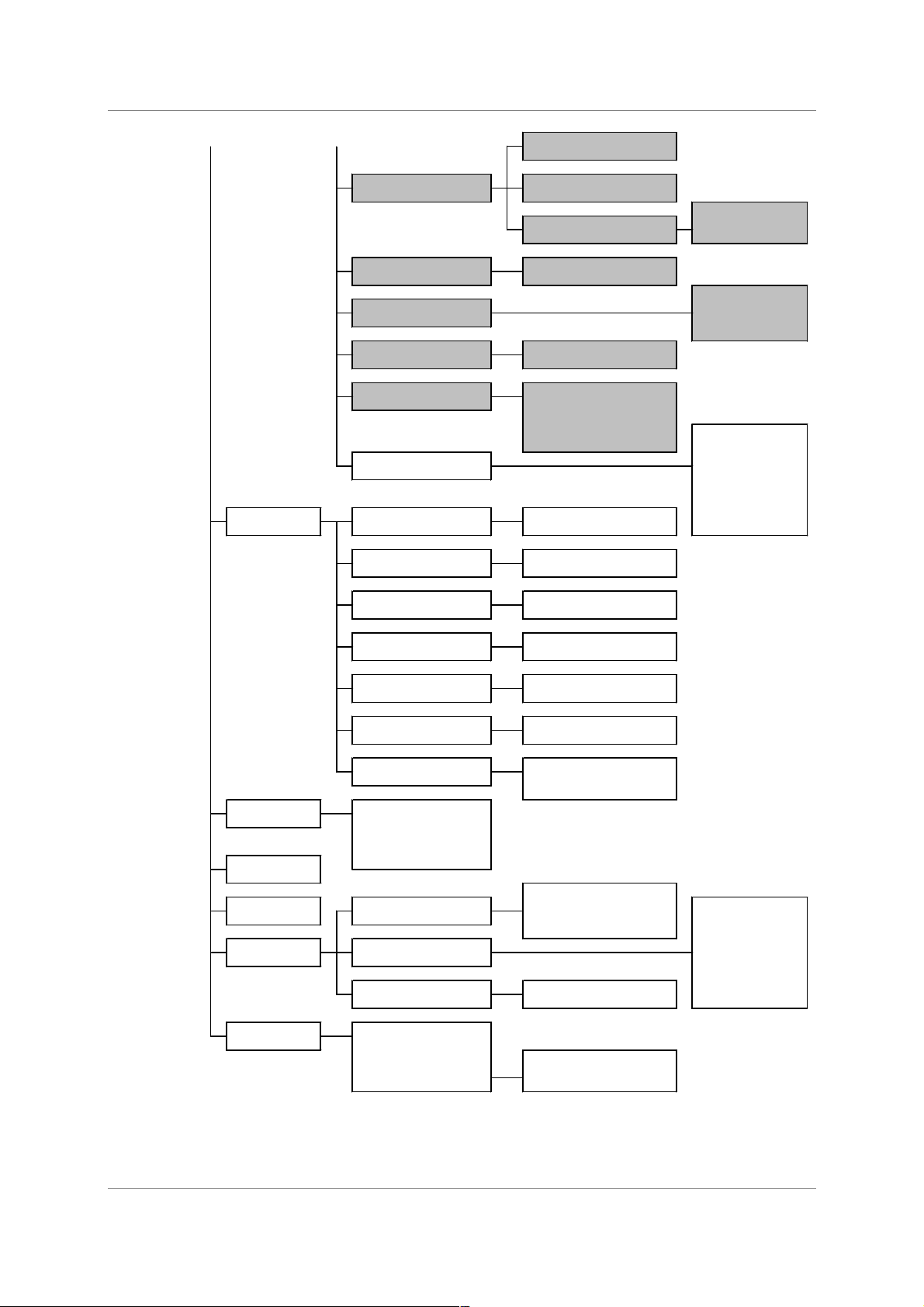
dCS 972 User Manual Manual for Software Version 2.3x
dCS Ltd January 2001
Manual part no: DOC1241102C2
Page 19
Document No: OS-MA-A0124-110.2C2
Contact
dCS
on + 44 1799 531 999 email to: more@dcsltd.co.uk
(inside the UK replace + 44 with 0) web site: www.dcsltd.co.uk
Reset max hold
Display max hold
Maximise!
Normal
Swapped
Normal
Left inverted
Right inverted
Both inverted
On
Off
Off
De-emphasis 50/15 usec +/- = add or remove
De-emphasis CCITT J17
Emphasis 50/15 usec +/- Input
Emphasis CCITT J17 +/- Sync Source
+/- Output Mode
+/- Word Length
+/- Noise Shaping
+/- Dither
Hold +/- L/R Flip
Reset +/- Filter
Hold
Reset
Hold
Reset
Hold
Reset
Hold
Reset
Hold
Reset
Hold
Unhold
Reset
Normal
Faster None
Fastest 320 ms
Instant 640 m s
960 ms
1280 ms
1600 ms
Bar
Infinite
Numerical
Reset
1 mins
3 mins
5 mins
…from "Top " …from "SRC"
Cursor
Backlight off after
Level Meters
Decay Time
Peak Hold
Display
Bri
g
htness
Contrast
Info
Bit Activity
Monitor
Test
Generator
Off/Sine/Square
Generator Amplitude
Generator Frequenc
y
Error Monitor
CRC Errors Left
CRC Errors Right
Parity Errors Left
De/Pre-emphasis
Display Customise
Self Test
Parity Errors Right
Invalid Errors Left
Invalid Errors Right
All Errors
Maximise
Phase
Swap Channels
Detect Silence
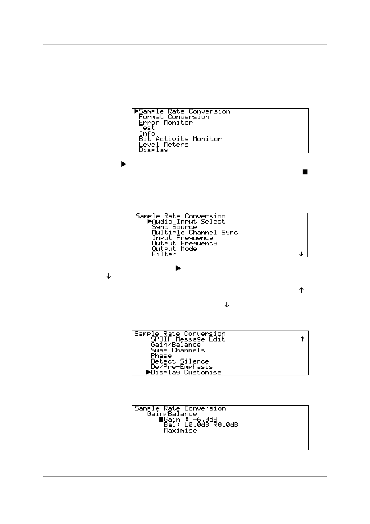
Gain/Balance
Gain adjust
Balance adjust
Meter Type
Table 1 – Menu Tree
dCS 972 User Manual Manual for Software Version 2.3x
dCS Ltd January 2001
Manual part no: DOC1241102C2
Page 20
Document No: OS-MA-A0124-110.2C2
Contact
dCS
on + 44 1799 531 999 email to: more@dcsltd.co.uk
(inside the UK replace + 44 with 0) web site: www.dcsltd.co.uk
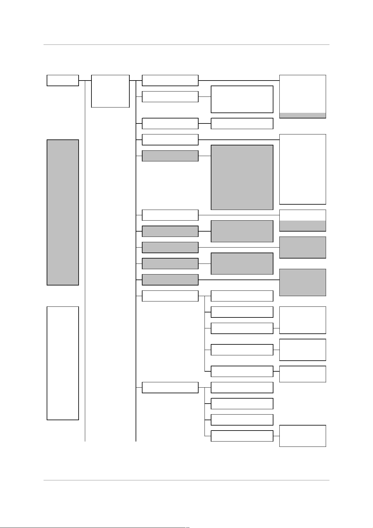
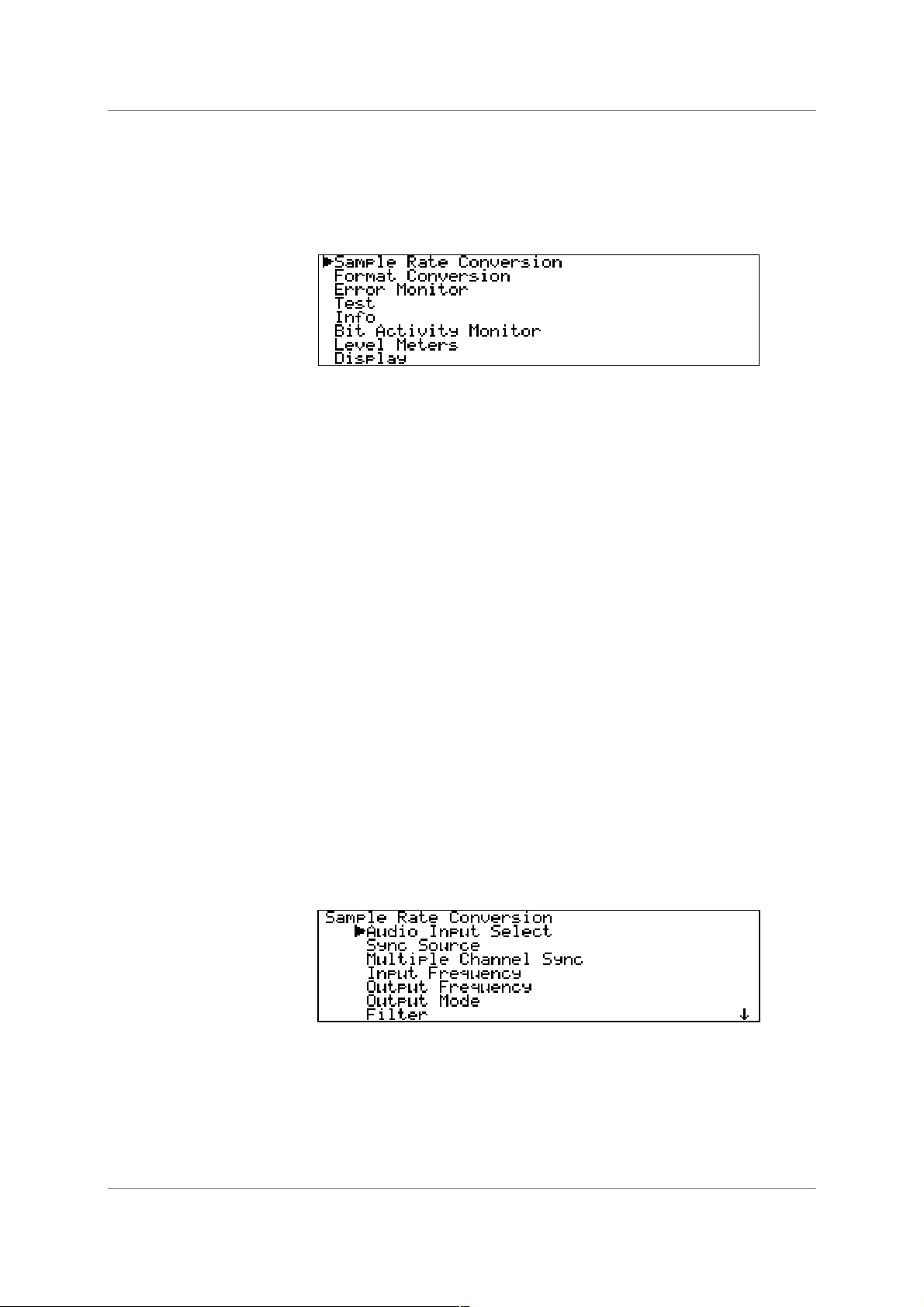
Top Menu
The top menu contains the major entries: - Sample Rate Conversion, Format
Conversion, Error Monitoring, Test, Info, Bit Activity Monitors, Level Meters
and Display – as follows:
In many cases, the settings in one menu do not affect those in others. In other
cases they do, and where this occurs the menu will automatically adjust to allow
only valid options.
The unit can operate in one of two main modes – Sample Rate Converter
(SRC) mode and Format Converter (FC) mode. In SRC mode, the unit
performs DSP on the signal and gain is always reduced by 0.01dB
4
. This is
because many of the other operations, such as dithering or noise shaping, add a
small amplitude signal, so we reduce the amplitude a small amount to prevent
spurious clips.
It also means that for simple operations such as Dual AES in to double speed
AES out, bits in will not be the same as bits out. Because in some cases this is
important, the unit can also operate in FC mode. FC mode has no (0dB) signal
drop, and will not allow operations that can cause audio data bit changes – but it
does allow bit for bit copies of signals to be made in different digital formats. It
also allows message editing, but many of the other options available in SRC
mode are removed from the menus while FC mode is active.
SRC mode offers all the options of FC mode – FC mode just turns off the options
that affect bit for bit performance. There are no options that are just available in
FC mode.
Sample Rate Conversion
The default setting is Sample Rate Conversion (SRC) mode on, Format
Conversion (FC) mode Off. Pressing →
→→
→ will enter the Sample Rate
Conversion menu.
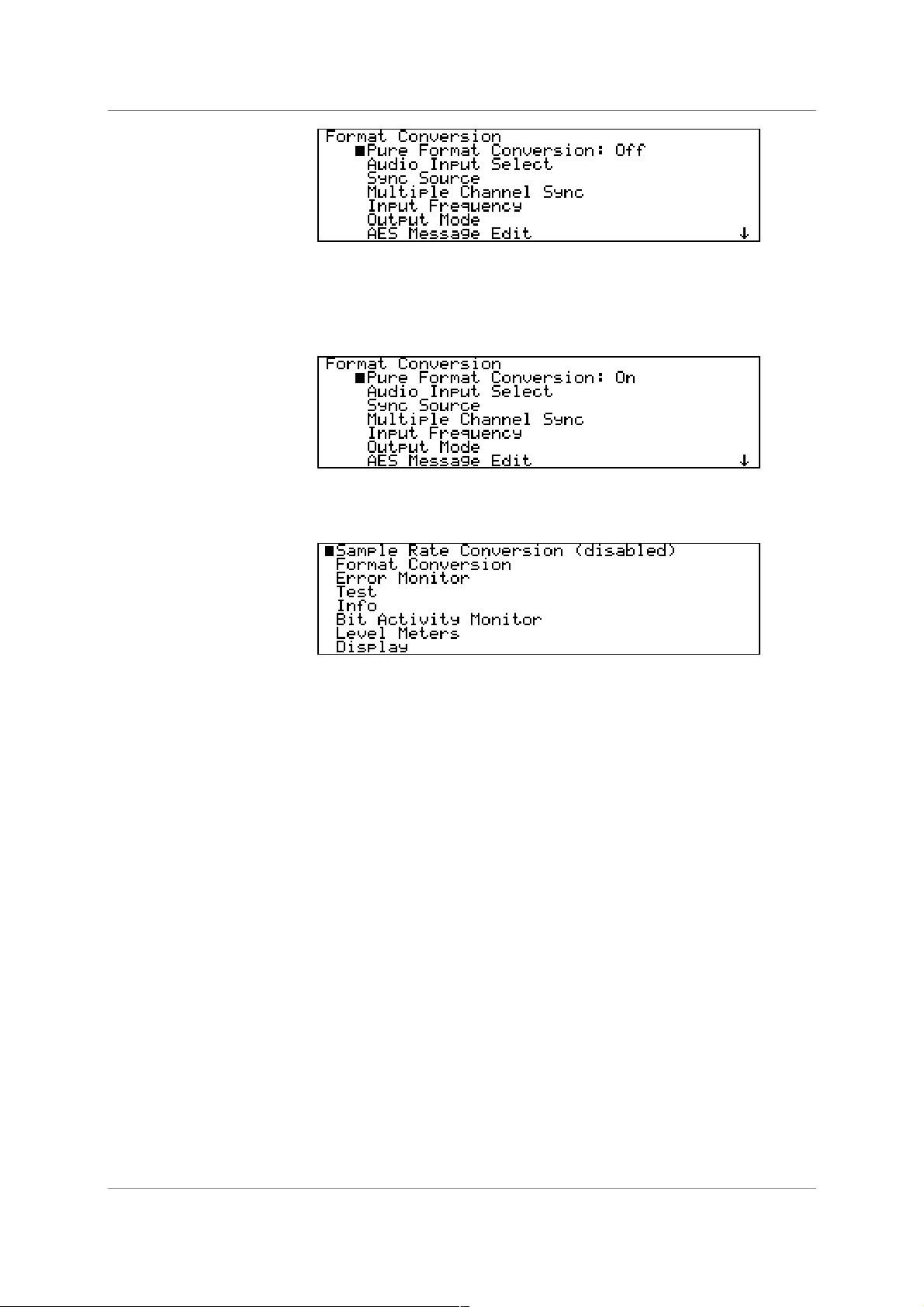
Format Conversion
The default setting is SRC mode on, FC mode Off. To turn FC mode on, select
Format Conversion and press →
→→
→. The menu below will appear:
4
in older versions of software, this was 0.1dB.
dCS 972 User Manual Manual for Software Version 2.3x
dCS Ltd January 2001
Manual part no: DOC1241102C2
Page 21
Document No: OS-MA-A0124-110.2C2
Contact
dCS
on + 44 1799 531 999 email to: more@dcsltd.co.uk
(inside the UK replace + 44 with 0) web site: www.dcsltd.co.uk
Pressing Set will toggle the state from Off to On. The unit will check to see if the
Output Frequency is the same as the Input Frequency, and if it is not it asks
you to press Set to change the Output Frequency, or any other key to cancel
the attempt to turn FC mode on.
On returning to the main menu, Sample Rate Conversion is shown as
disabled:
To re-enter SRC mode, you have to set Format Conversion to Off.
Error Monitoring
Error monitoring on the input signal can be implemented for CRC, parity and
Valid bits in the AES3 and SPDIF message streams. This menu covers resetting
the monitors, and is only available for PCM inputs – the entry disappears for
DSD inputs.
Test
The unit can be used as a very high purity signal generator, as well as
performing self test functions, via this menu.
Info
This menu displays information about the unit, for support purposes
Bit Activity Monitors
This menu turns on bit activity monitors on the selected input signal, for use on
the audio data – it can find out how many bits you have coming in, or identify
stuck bits in other equipment. This only works for PCM inputs – the entry
disappears for DSD inputs. This feature does NOT monitor the units outputs.

dCS 972 User Manual Manual for Software Version 2.3x
dCS Ltd January 2001
Manual part no: DOC1241102C2
Page 22
Document No: OS-MA-A0124-110.2C2
Contact
dCS
on + 44 1799 531 999 email to: more@dcsltd.co.uk
(inside the UK replace + 44 with 0) web site: www.dcsltd.co.uk
Level Meters
Controls level metering of the output data. The level meters may be used to
monitor DSD signals by setting a DSD to PCM conversion. Even though the
conversion may not be used, the level metering will effectively meter the DSD
input.
Display
Controls the Brightness, Contrast, Cursor direction and Backlight timeout
behaviour of the display.

dCS 972 User Manual Manual for Software Version 2.3x
dCS Ltd January 2001
Manual part no: DOC1241102C2
Page 23
Document No: OS-MA-A0124-110.2C2
Contact
dCS
on + 44 1799 531 999 email to: more@dcsltd.co.uk
(inside the UK replace + 44 with 0) web site: www.dcsltd.co.uk

dCS 972 User Manual Manual for Software Version 2.3x
dCS Ltd January 2001
Manual part no: DOC1241102C2
Page 24
Document No: OS-MA-A0124-110.2C2
Contact
dCS
on + 44 1799 531 999 email to: more@dcsltd.co.uk
(inside the UK replace + 44 with 0) web site: www.dcsltd.co.uk
Sample Rate Conversion / Format Conversion Submenu
The Sample Rate Conversion menu is as follows:
Audio Input Select
Select the required input from the list and press Set. The Dual AES option
requires that the Input Frequency be set to 192 kS/s, 176.4 kS/s, 96 kS/s or
88.2 kS/s. Selecting DSD will select the SDIF set of inputs.
Sync Source
Select a source to synchronise to from the list and press Set. The available sync
sources are:
AES AES Clock In (the AES reference input)
Word Clock SDIF-2 Input Clk
Audio Input Syncs to the selected input source – this is the
normal setting.
Internal Syncs to the dCS 972’s internal clock
Lab Ref Syncs to a 10 MHz signal into SDIF-2 Input Clk
For best results, synchronise to the Audio Input or a master clock on one of the
clock/reference inputs that is also driving the source. For DSD, a Word Clock
must be used – contact dCS if you need a Bit Clock. The Lab Ref setting allows
use of a GPS reference - if you use this, make sure other parts of your system
are also GPS sync’d.
Only select Internal sync if you are using the unit as a signal generator or a
reference clock source.
Multiple Channel Sync
This option is either On or Off.
The unit uses the AES Clk Input as a sync link. When On, if the unit detects a
sync signal into the AES Clk Input, it will sync to it and set up as a Slave. If
there is no sync signal coming into the AES Clk Input, it will set up as a Master.
See section Multiple Channel Sync’ing, page 68 for an explanation, or the
section Multi-channel Sample Rate Conversion – bit aligned sources, page
52 for wiring. Do not feed a signal with active User bits into the AES Clk Input
with Multiple Channel Sync turned on!

dCS 972 User Manual Manual for Software Version 2.3x
dCS Ltd January 2001
Manual part no: DOC1241102C2
Page 25
Document No: OS-MA-A0124-110.2C2
Contact
dCS
on + 44 1799 531 999 email to: more@dcsltd.co.uk
(inside the UK replace + 44 with 0) web site: www.dcsltd.co.uk
When the option is On, the Status display informs you about the unit’s
configuration. If an active signal is connected to the AES Clk Input, but it does
not carry User bits, the unit thinks it is a Single unit, and the Status display is as
follows:
If no signal is connected into the AES Clk Input (there is no sync link going in),
the unit thinks it is a Master and the Status display is as follows:
If the sync link is connected and active, the unit thinks it is a Slave, and the
Status display shows:
For multi channel syncing on DSD to DSD, the sync link does not synchronise all
the output Word Clocks. Each unit will have a different phase. Just use the
Word Clock from one unit and ignore the rest – the group delays for the signals
will not be affected.
Input Frequency (Sample Rate)
For PCM operation, the input sample rate can be sensed and set automatically,
using the Auto option, or forced. The latter is useful where use of 1 or 2 wire
mode for higher sample rates might be ambiguous – otherwise Auto is best. It
occurs at the bottom of the Input Frequency list:

dCS 972 User Manual Manual for Software Version 2.3x
dCS Ltd January 2001
Manual part no: DOC1241102C2
Page 26
Document No: OS-MA-A0124-110.2C2
Contact
dCS
on + 44 1799 531 999 email to: more@dcsltd.co.uk
(inside the UK replace + 44 with 0) web site: www.dcsltd.co.uk
Select the required entry from the list and press Set. If you have selected Auto,
then the list changes when re-entered:
and the Status display will indicate that Auto is on:
Output Frequency (Sample Rate)
Output Frequency is a parameter for PCM operation only. Select the required
Output Frequency from the list and press Set. The dCS 972 accepts 96 input /
output frequency combinations in one pass. The remaining 48 combinations can
be accommodated in 2 passes. These are shown in the table below:
OUTPUT FREQUENCY (kS/s)
11.025 12 16 22.05 24 32 44.1 48 88.2 96 176.4 192
11.025 1 pass 1 pass 2 pass 1 pass 1 pass 2 pass 1 pass 2 pass 1 pass 2 pass 2 pass 2 pass
12 1 pass 1 pass 2 pass 1 pass 1 pass 2 pass 2 pass 1 pass 2 pass 1 pass 2 pass 2 pass
16 2 pass 2 pass 1 pass 1 pass 1 pass 1 pass 1 pass 1 pass 2 pass 1 pass 2 pass 2 pass
22.05 1 pass 1 pass 1 pass 1 pass 1 pass 2 pass 1 pass 1 pass 1 pass 2 pass 2 pass 2 pass
24 1 pass 1 pass 1 pass 1 pass 1 pass 2 pass 1 pass 1 pass 2 pass 1 pass 2 pass 2 pass
32 2 pass 2 pass 1 pass 2 pass 2 pass 1 pass 1 pass 1 pass 1 pass 1 pass 2 pass 2 pass
44.1 1 pass 1 pass 1 pass 1 pass 1 pass 1 pass 1 pass 1 pass 1 pass 1 pass 1 pass 1 pass
48 1 pass 1 pass 1 pass 1 pass 1 pass 1 pass 1 pass 1 pass 1 pass 1 pass 1 pass 1 pass
88.2 1 pass 1 pass 1 pass 1 pass 1 pass 1 pass 1 pass 1 pass 1 pass 1 pass 1 pass 1 pass
96 1 pass 1 pass 1 pass 1 pass 1 pass 1 pass 1 pass 1 pass 1 pass 1 pass 2 pass 1 pass
176.4 2 pass 2 pass 2 pass 2 pass 2 pass 2 pass 1 pass 2 pass 1 pass 2 pass 1 pass 2 pass
INPUT FREQUENCY (kS/s
)
192 2 pass 2 pass 2 pass 2 pass 2 pass 2 pass 1 pass 1 pass 1 pass 1 pass 2 pass 1 pass
Table 2 – One Pass and Two Pass Conversions
Not all the apparently valid output frequencies may be available to you from the
menu. When Auto Input Frequency Selection is turned on, the menu system
dynamically alters the Output Frequency menu to reflect the valid 1 pass
output frequencies for the current input frequency. For example, if Auto is
turned on and the input is running at 96 kS/s, then the Output Frequency
menu would look like this:

dCS 972 User Manual Manual for Software Version 2.3x
dCS Ltd January 2001
Manual part no: DOC1241102C2
Page 27
Document No: OS-MA-A0124-110.2C2
Contact
dCS
on + 44 1799 531 999 email to: more@dcsltd.co.uk
(inside the UK replace + 44 with 0) web site: www.dcsltd.co.uk
If the input frequency were 32 kS/s, then the display would offer a different
selection:
The input frequency can be changed to one that is incompatible with the
currently selected Output Frequency, because it needs a 2 pass operation. As
an example, we might have 11.025 kS/s coming in (not on Auto), and try and
select 96 kS/s. The dCS 972 will detect that this ought to be a 2 pass operation
and display the following information box:
While displaying this information box, the output of the dCS 972 will be muted. To
continue, either:
do this: Change the input frequency to one suitable for conversion (see the table above)
or
do this: Press any key, and the dCS 972 will display a list of valid Output Frequencies,
as follows (for our 11.025 kS/s example)
For 2 Pass conversion, convert the input to an intermediate frequency and
either feed it direct into another dCS 972 or record the result, then convert from
the intermediate frequency to the required frequency. You can always choose
one of 44.1 kS/s or 48 kS/s as the intermediate frequency, so you can record
the intermediate pass on most recording devices. However, it is best to use the
highest possible sample rate for the intermediate pass, if your recording device
can take it. For example, to convert from 192 kS/s to 12 kS/s, first convert from
192 kS/s to 96 kS/s, and then convert from 96 kS/s to 12 kS/s. Use of two dCS
972’s avoids intermediate storage.
dCS 972 User Manual Manual for Software Version 2.3x
dCS Ltd January 2001
Manual part no: DOC1241102C2
Page 28
Document No: OS-MA-A0124-110.2C2
Contact
dCS
on + 44 1799 531 999 email to: more@dcsltd.co.uk
(inside the UK replace + 44 with 0) web site: www.dcsltd.co.uk
Output Mode
For DSD output, select DSD SDIF-2 or DSD SDIF-3, and the unit will make the
appropriate changes. The unit supports DSD out with either DSD or PCM in.
DSD output includes a DSD DC blocking filter. All signals in DSD or PCM will
have their DC filtered out. In this mode, the 3 AES and 3 SPDIF outputs all carry
identical AES streams with no data – they may be used for synchronisation.
For PCM output, select Dual AES to output a 192kS/s, 176.4kS/s, 96 kS/s or
88.2 kS/s AES3 signal on two cables – AES1 and AES2. In this mode, the AES
Clk Output and 3 SPDIF outputs all carry identical AES streams with no data –
they may be used for synchronisation. The SDIF Clk Output sends Wordclock,
do not use the SDIF data outputs while in Dual AES mode.
Otherwise set to Normal. For PCM out, the unit can have PCM or DSD in.
Filter
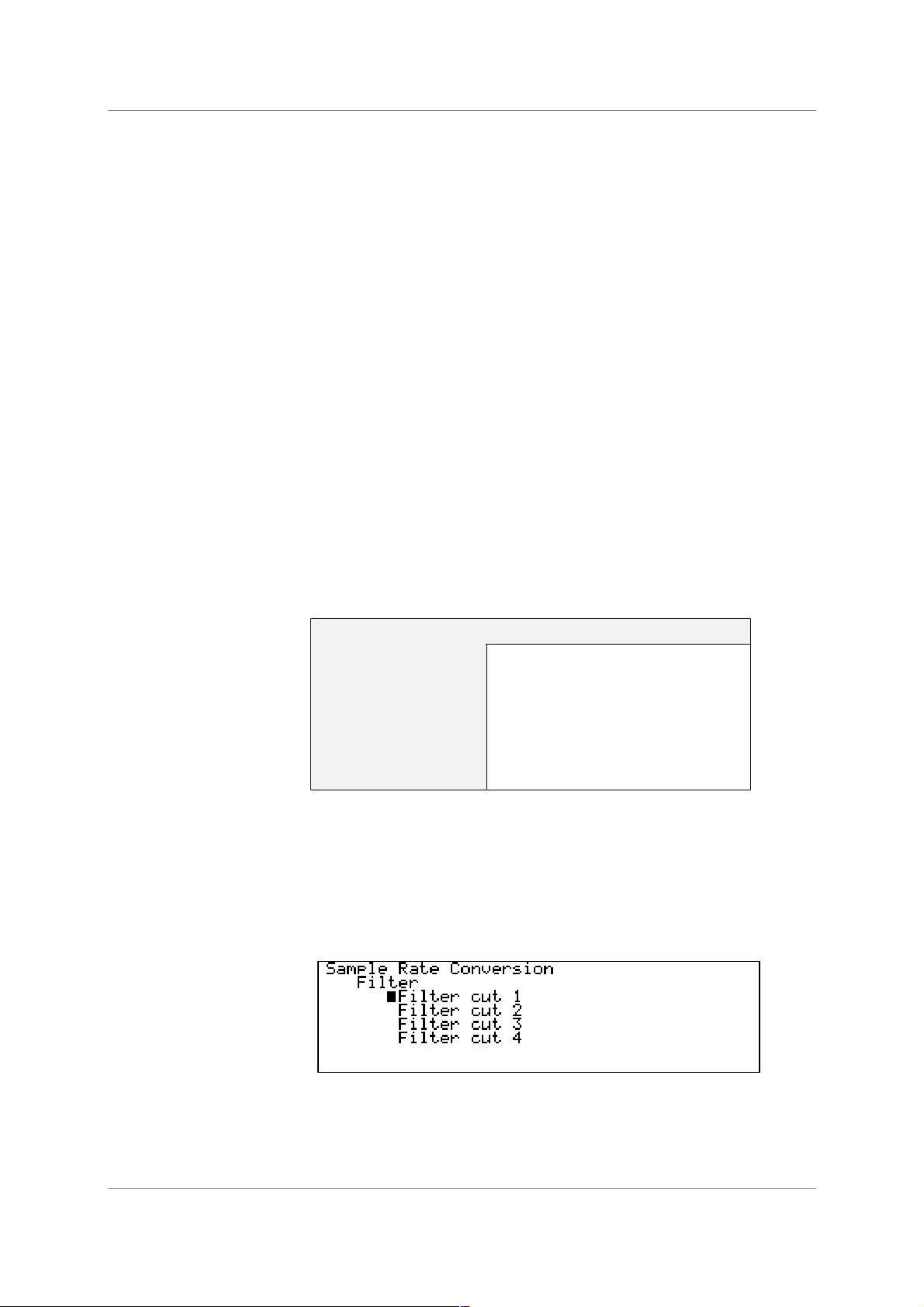
The dCS 972 offers a choice of filter for use on some of the more popular in/out
combinations. The filters offer differing responses. For PCM outputs, Filter 1 in
each case offers the sharpest cut-off and no or least aliasing, but longest energy
smear. Filter 4 gives the gentlest roll-off (usually with significant aliasing) but the
shortest transient response with least smear. For DSD output, the differences
are not so great – the responses are given in the section dCS 972 Performance
Curves, page 80.
The conversions that offer multiple filters are as follows:
In Out Number of Filters Available
DSD DSD 4
PCM DSD 4
192 96 4
96 48 4
96 44.1 4
48 44.1 4
44.1 96 4
Table 3 – Conversions with Multiple Filter Options
We encourage you to experiment with the filters, to find the one that sounds
best for your particular application. Do not assume that one filter is best for all
applications!
5
The menu is dynamic - that is, it updates to show valid selections. For example,
Fs In = 96kHz, Fs Out = 44.1kHz has 4 options and shows:
While Fs In = 96kHz, Fs Out = 88.2kHz has only one option and shows:
5
The reports we receive from users suggest that for PCM work, Filter 2 is well suited to some classical music,
and that Filters 3 and sometimes 4 suit rock. However, views vary quite a lot.
dCS 972 User Manual Manual for Software Version 2.3x
dCS Ltd January 2001
Manual part no: DOC1241102C2
Page 29
Document No: OS-MA-A0124-110.2C2
Contact
dCS
on + 44 1799 531 999 email to: more@dcsltd.co.uk
(inside the UK replace + 44 with 0) web site: www.dcsltd.co.uk
The dCS 972 remembers the last filter selection for every conversion, so if you
choose Filter 4 for 96Ö44.1 and Filter 2 for 96Ö48, these separate settings will
be stored and loaded when you switch between them.
Output Word Length.
Select the required Word Length from the list and press Set.
IMPORTANT!
The dCS 972 generates long word length (24 bit) data and truncating this
adds extra noise. It can also add highly undesirable behaviour at low signal
levels. We recommend that you use a high order noise shaping function, but
see the section Word Length Reduction, page 90 and try for yourself.
This is a seriously major topic, and you should experiment.
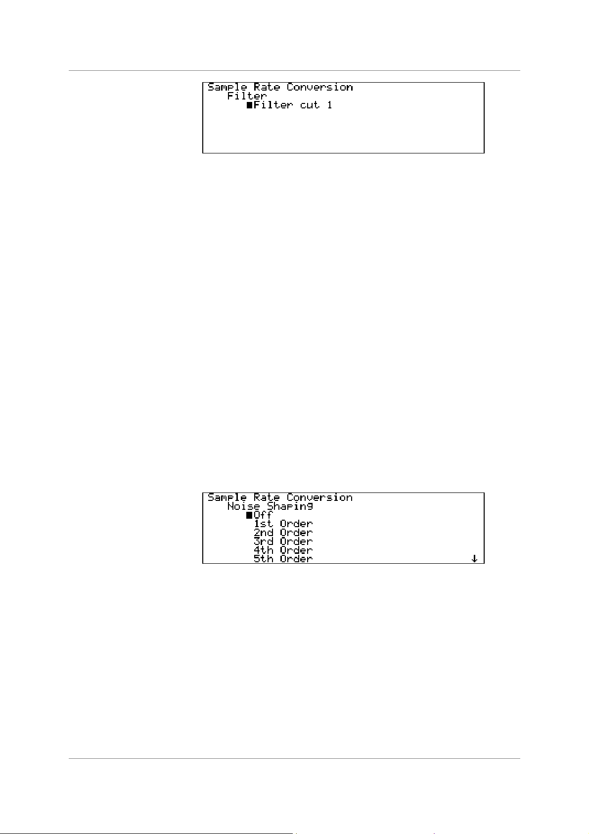
Noise Shaping
Noise Shaping is a technique in which the noise energy added by truncating a
longer word is pushed into the less audible parts of the spectrum - giving a
useful improvement in perceived noise level. There is a trade-off between noise
floor improvements in the mid-band, where the ear is most sensitive, and
increased noise at the top of the audio band, which the ear does not hear but
your system might. Noise Shaping is achieved by processing the truncated bits
so it is not available if the output word length is the same as the input word
length. Dither is different (and additional) to Noise Shaping, and is necessary
under some circumstances. dCS consider Dither to be unnecessary in many
situations - Noise Shaping alone is sufficient, and lower noise. See the section
Word Length Reduction, page 90 for more information. Entering the menu
shows:
Select the required Noise Shaping characteristic from the list and press Set.
The options are up to 10
th
order, for sample rates up to 96kS/s. Noise Shaping
is not applicable to DSD. For 32 kS/s, 44.1 kS/s, 48 kS/s, 88.2 kS/s and 96 kS/s
the curves are individually optimised
6
.
6
If you need curves optimised at other sample rates, contact us.
dCS 972 User Manual Manual for Software Version 2.3x
dCS Ltd January 2001
Manual part no: DOC1241102C2
Page 30
Document No: OS-MA-A0124-110.2C2
Contact
dCS
on + 44 1799 531 999 email to: more@dcsltd.co.uk
(inside the UK replace + 44 with 0) web site: www.dcsltd.co.uk
Dither
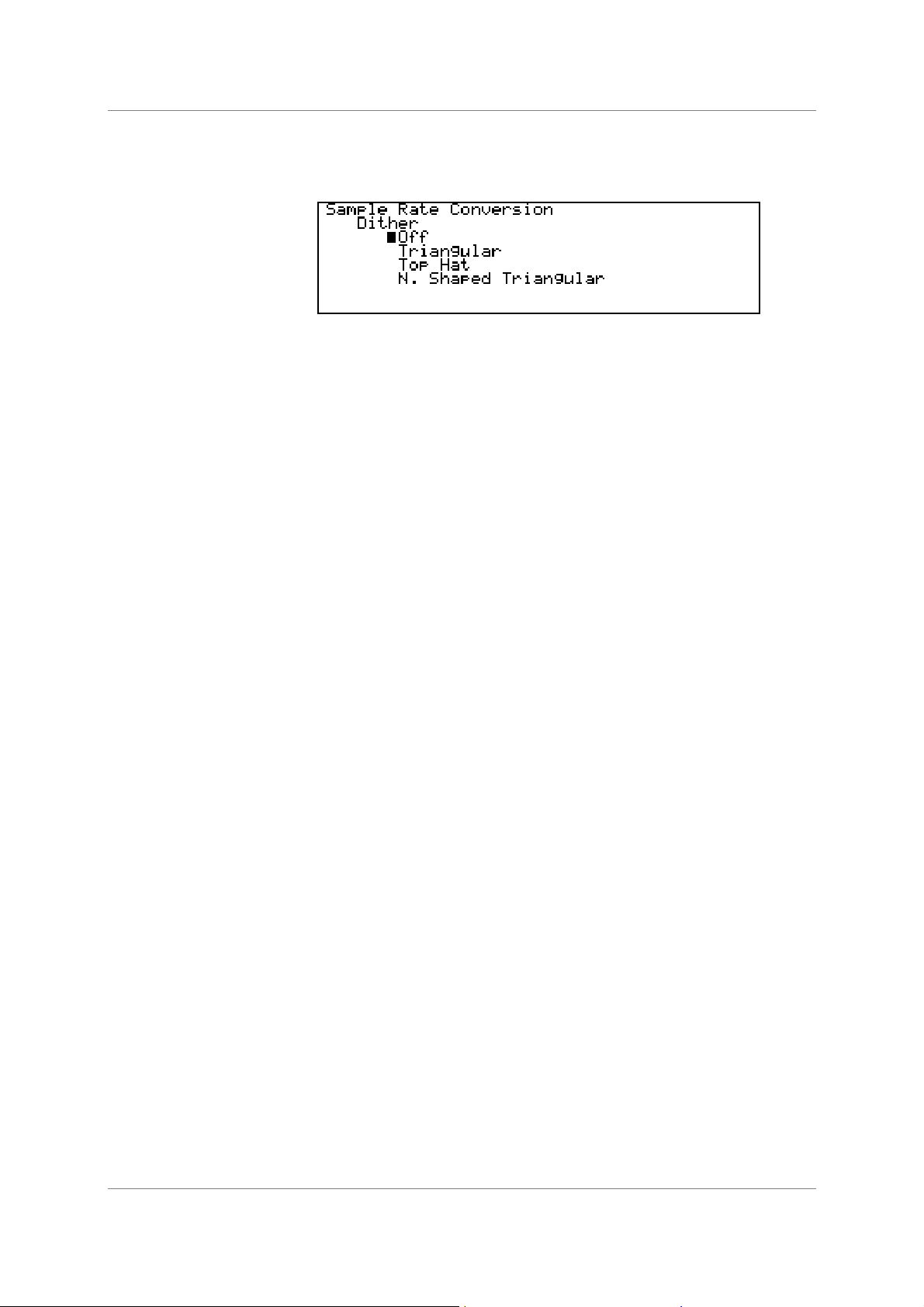
Entering the Dither submenu shows:
Select the required Dither characteristic from the list and press Set.
N. Shaped Triangular means Noise Shaped Triangular.
For more information on dither, and different dither types, see the section Dither
on page 72 and Figure 25 to Figure 28.
AES Message Edit
This menu sets the message bits on the AES outputs.
Professional On/Off Select then press Set to toggle between On and
Off.
Non-Audio On/Off Select then press Set to toggle between On and
Off.
Mode Select the audio data format then press Set.
Options are:
Not indicated
Two channel
Primary/Secondary
Stereophonic
Source Select each of the four bytes in turn, press Set,
turn the rotary control to change the character as
necessary and press Set again to accept. Press
←
←←
← to return to the previous menu and the four
characters will be displayed beside “Source”.
Destination Set up similarly to Source.
SPDIF Message Edit
This menu sets the message bits on the SPDIF outputs.
Professional On/Off Select then press Set to toggle between On and
Off.
Non-Audio On/Off Select then press Set to toggle between On and
Off.
Copy Permit On/Off Select then press Set to toggle between On and
Off.
Format Select the audio data format then press Set.
Options are:
2 Channel General Format
Compact Disk
2 Channel Encode/Decode
DAT
Loading...