


dCS 954
Digital to Analogue Converter
User Manual
Standard software version 1.5x
P3D software version 1.36
June 2000
© 1997, 1999, 2000 dCS Ltd
All rights reserved. Reproduction of this manual in any manner whatsoever, without the written permission of dCS1 is strictly forbidden. Additional copies of this manual may be obtained from dCS.
Information contained in this manual is subject to change without notice, and whilst it is checked for accuracy, no liabilities can be accepted for errors.
1 |
dCS |
Ltd is Data Conversion Systems Ltd. Company registered in England, UK, no. 2072115 |
|

dCS 954 User Manual |
Manual for Standard Software Version 1.5x |
dCS Ltd |
June 2000 |
|
|
Manual part no: DOC136954 iss 2B1 |
Page 2 |
file 135954ma2b1.pdf available from website |
Contact dCS on + 44 1799 531 999 |
email to: more@dcsltd.co.uk |
(inside the UK replace + 44 with 0) |
web site: www.dcsltd.co.uk |

dCS 954 User Manual |
Manual for Standard Software Version 1.5x |
dCS Ltd |
June 2000 |
|
|
PRODUCT FEATURES
Formats
•DSD, and PCM from 192 kS/s down to 32 kS/s
•Data formats supported are: AES/EBU (XLR and BNC), Dual AES (XLR), Quad AES (XLR), AES data at TTL levels, and SDIF-2 (PCM and DSD), SDIF-3 (DSD), DSD packed into 4 AES links
•P3D option: DSD packed into 3 AES links
Syncing
•Can sync to Word Clock or AES reference, or input signal, and sync to video option available
Functions
•Very high performance DAC, free from gain ranging
•High quality VCXO internal clocking
•Multichannel Sync capability
•High speed or dual AES (88.2 kS/s, 96 kS/s)
•Dual or Quad AES (176.4 kS/s and 192 kS/s)
•DDC mode converts Dual AES at 88.2 to 192kS/s or Quad AES at 176.4 or 192kS/s to High speed Single AES
Test Generator
•High quality (160 dB) signal generator with mHz resolution. Can be noise shaped truncated
Ease of Use
•Remembers last settings
•Lockouts
•Software upgrade-able without opening the box
•Can be remote controlled from PC
Manual part no: DOC136954 iss 2B1 |
Page 3 |
file 135954ma2b1.pdf available from website |
Contact dCS on + 44 1799 531 999 |
email to: more@dcsltd.co.uk |
(inside the UK replace + 44 with 0) |
web site: www.dcsltd.co.uk |

dCS 954 User Manual |
|
Manual for Standard Software Version 1.5x |
|
dCS Ltd |
|
|
June 2000 |
CONTENTS |
|
|
|
Product Features ................................................................................................ |
|
3 |
|
CONTENTS.......................................................................................................... |
|
4 |
|
|
About this Manual |
|
5 |
Using Your dCS 954 For The First Time ............................................................ |
6 |
||
|
Product Overview |
|
6 |
|
What’s in the Box? |
|
6 |
|
Mains Voltages |
|
6 |
|
Installing Unit in a Rack |
|
7 |
|
Getting Started |
|
8 |
The Hardware – Controls and Connectors..................................................... |
10 |
||
|
Rear Panel |
|
10 |
|
Front Panel |
|
12 |
The Software – the Menu ................................................................................. |
|
18 |
|
|
Overview |
|
18 |
|
The Menu Sequence |
|
19 |
|
Menu Items |
|
20 |
Typical Applications......................................................................................... |
|
30 |
|
|
Using a dCS 954 for DSD |
|
30 |
|
Using a Master Clock to Sync a dCS 954 |
30 |
|
|
Replaying DSD from an 8 track 16/44.1 PCM Recorder |
31 |
|
|
Operating Several Units on One Remote Chain |
31 |
|
|
Six Channel PCM Set Up |
|
32 |
|
Replaying 6 channel DSD from a 24 track 16/44.1 PCM Recorder |
33 |
|
|
Replaying 8 Channel P3D DSD |
|
34 |
|
Upsampling a CD |
|
35 |
|
Converting Quad AES to Single AES |
|
36 |
|
Converting 4-wire DSD to SDIF DSD |
|
36 |
|
Replaying 24/192 from 2 Nagra-D recorders |
37 |
|
dCS 954 Technical Information......................................................................... |
|
38 |
|
|
Anti Image Filtering |
|
38 |
|
Clocking |
|
39 |
|
DSD |
|
40 |
|
Sample Alignment |
|
41 |
|
Digital Interface Specifications |
|
45 |
|
Analogue Interface Specifications |
|
46 |
|
Frequency Response |
|
47 |
|
Group Delay |
|
48 |
|
AES3 (AES/EBU) Format |
|
49 |
|
SDIF-2 |
|
52 |
|
P3D Behaviour |
|
55 |
|
RS-232 Remote Control Interface |
|
56 |
|
Power Consumption |
|
65 |
|
Size and Weight |
|
65 |
|
Operating Conditions |
|
66 |
General Technical Information........................................................................ |
|
68 |
|
|
Jitter and PLL bandwidths |
|
68 |
Options .............................................................................................................. |
|
70 |
|
Maintenance and Support................................................................................ |
|
72 |
|
|
Hardware |
|
72 |
|
Software |
|
73 |
|
Hardware Update or Calibration |
|
74 |
|
Warranty |
|
74 |
Manual part no: DOC136954 iss 2B1 |
Page 4 |
file 135954ma2b1.pdf available from website |
|
Contact dCS on + 44 1799 531 999 |
email to: more@dcsltd.co.uk |
(inside the UK replace + 44 with 0) |
web site: www.dcsltd.co.uk |

dCS 954 User Manual |
Manual for Standard Software Version 1.5x |
|
dCS Ltd |
|
June 2000 |
|
Safety and Electrical Safety |
74 |
|
TroubleShooting............................................................................................... |
76 |
|
Error Codes and Messages |
76 |
|
Internal Device Error Codes |
76 |
|
System Messages and Error Codes |
77 |
|
Trouble Shooting Your System |
77 |
|
dCS Support....................................................................................................... |
80 |
|
I wish .... |
80 |
|
If You Need More Help |
80 |
|
Other Information |
80 |
|
Indexes and Software Version Numbers........................................................ |
81 |
|
Definitions of Units |
81 |
|
Full Contents |
82 |
|
Tables |
85 |
|
Figures |
86 |
|
Keywords and Phrases |
87 |
About this Manual
Note that there is a fuller Contents at the end of the manual (page 82), along with an index and lists of figures and tables.
References to other sections in the text have the "Section Name” page … in quotation marks and bolded.
IMPORTANT! Important information is presented like this - ignoring this may cause you to damage the unit, or invalidate the warranty.
The manual covers standard units and units with P3D option. P3D is a DSD data format, and these units have changed internal hardware to accommodate it. Information that is specific to P3D units is greyed.
The manual is designed to be helpful. If there are points you feel we could cover better, or that we have missed out - please tell us.
Manual part no: DOC136954 iss 2B1 |
Page 5 |
file 135954ma2b1.pdf available from website |
Contact dCS on + 44 1799 531 999 |
email to: more@dcsltd.co.uk |
(inside the UK replace + 44 with 0) |
web site: www.dcsltd.co.uk |

dCS 954 User Manual |
Manual for Standard Software Version 1.5x |
dCS Ltd |
June 2000 |
|
|
USING YOUR dCS 954 FOR THE FIRST TIME
Product Overview
The dCS 954 DAC (Digital to Analogue Converter) is a high performance converter intended for studio and live recording applications. It is designed to produce very high standard analogue output from high quality digital data formats (for example, 192 kS/s or DSD) or standard formats (for example Red Book CD or 24/96). AES3, SDIF-2 PCM formats and several DSD formats are all supported. Multiple units may be slaved to a master clock for stable multichannel operation.
The unit is mains powered and is housed in a 1U (1.75”) high 19” rack mounting case. It may be controlled either from its front panel, or from a software based remote control running on a PC. The last setting is automatically stored on power down, so that fixed installations may be set up at leisure, installed and then left alone. Unauthorised alterations to settings may be prevented by a “front panel lockout” feature.
The unit is highly software based, and more functions and features will be added from time to time. Software updates from dCS are free!2
What’s in the Box?
The contents of the box are at least:
dCS 954
User Manual Function Menu Guide Mains Lead
2 Spare Fuses Remote cable Remote software
Mains Voltages
The dCS 954 is shipped with its mains voltage preset for operation in the destination country. The voltage is not intended to be changed by the user. If it needs to be changed, contact your dealer or dCS.
IMPORTANT! The dCS 954 must be used with a mains earth!
2Free if we email them, and you download from a PC com port. Low cost if you ask us for EPROMs or other media - we charge for media and handling.
Manual part no: DOC136954 iss 2B1 |
Page 6 |
file 135954ma2b1.pdf available from website |
Contact dCS on + 44 1799 531 999 |
email to: more@dcsltd.co.uk |
(inside the UK replace + 44 with 0) |
web site: www.dcsltd.co.uk |

dCS 954 User Manual |
Manual for Standard Software Version 1.5x |
dCS Ltd |
June 2000 |
|
|
Installing Unit in a Rack
The unit is supplied with 19" rack mount ears fitted. If it is to be mounted in a 19" rack, the ears supplied may be used to locate it in the rack and stop the unit sliding forward – but they are not strong enough to support the unit.
IMPORTANT! The ears should not be used as the only mechanical support. The unit should rest on a shelf, or be supported in some other way. The ears will just locate it in the rack, and stop it sliding forwards.
If the unit is not to be rack mounted, the ears may be removed.
Manual part no: DOC136954 iss 2B1 |
Page 7 |
file 135954ma2b1.pdf available from website |
Contact dCS on + 44 1799 531 999 |
email to: more@dcsltd.co.uk |
(inside the UK replace + 44 with 0) |
web site: www.dcsltd.co.uk |

dCS 954 User Manual |
Manual for Standard Software Version 1.5x |
dCS Ltd |
June 2000 |
|
|
Getting Started
Here’s what to do:
(If the unit does not behave the first time you power up – contact your dealer, or dCS.)
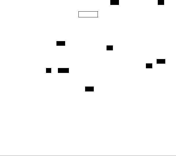
do this: Check the appropriate mains supply for your local mains is marked on the rear panel.
do this: If it is, using the lead supplied, connect the unit to the mains - connect no other leads at this stage - and switch on.
The 7 segment display will briefly show:
- - - - 4
and then indicates that it is out of lock:
o u t
do this: Ensure your system volume is set to a low level, then connect the analogue outputs (either balanced or unbalanced) to the inputs of your pre or power amplifier.
do this: Connect the digital output of a CD player or recorder to the AES1 input and if the AES1 input is not already selected, press the AES1 button to select it.
MAINS FUSE 2A(T) ON OFF
V 50-60Hz Disconnect mains before removing cover
Remove |
|
Fit |
|||||
old fuse |
new fuse |
||||||
|
|
|
|
|
|
|
|
|
|
|
|
|
|
|
|
|
|
|
|
|
|
|
|
Figure 1 – Playing a CD
The unit will detect the sample rate, lock to it and unmute. The display will show the sample rate, for example:
4 4. 1
do this: If the Mute LED is still lit, press the Mute button once. You should have audio.
Note that the balanced and unbalanced outputs are active simultaneously on the dCS 954 and may both be connected to external equipment simultaneously if required.
Now you will need to familiarise yourself with how the front panel controls and the menu system work.
do this: Read the short section on “The Software – the Menu” on page 18 so you know how the buttons and menu work.
You may also find it convenient to refer to the Function Menu Guide while you are getting to know the unit.
Manual part no: DOC136954 iss 2B1 |
Page 8 |
file 135954ma2b1.pdf available from website |
Contact dCS on + 44 1799 531 999 |
email to: more@dcsltd.co.uk |
(inside the UK replace + 44 with 0) |
web site: www.dcsltd.co.uk |

dCS 954 User Manual |
Manual for Standard Software Version 1.5x |
dCS Ltd |
June 2000 |
|
|
Manual part no: DOC136954 iss 2B1 |
Page 9 |
file 135954ma2b1.pdf available from website |
Contact dCS on + 44 1799 531 999 |
email to: more@dcsltd.co.uk |
(inside the UK replace + 44 with 0) |
web site: www.dcsltd.co.uk |

dCS 954 User Manual |
Manual for Standard Software Version 1.5x |
dCS Ltd |
June 2000 |
|
|
THE HARDWARE – CONTROLS AND CONNECTORS
Rear Panel
CH1(L) |
CH2(R) |
Sensitivity |
CH1(L) CH2(R)
Reference In |
Reference Out |
AES1 |
AES2 |
AES3 |
AES4 |
CH1 |
CH2 In |
MAINS FUSE 2A(T) ON OFF |
PUSH |
PUSH |
PUSH |
PUSH |
PUSH |
In |
SDIF-2/DSD |
Out |
Remote |
75R |
Out |
||
|
Clk |
|
|
Analogue |
Digital I/O |
Figure 2 – Rear Panel
All input and output connectors are mounted on the rear panel. Individual connectors are clearly identified by the panel legend. Viewed from the rear from left to right, the connectors are as follows:
Balanced Analogue Outputs |
3 pin XLR male (2 off) |
Unbalanced Analogue Outputs |
RCA phono (2 off) |
Output Level Adjustment |
(trimmers) |
Two multi-turn potentiometers set the full scale output levels for the Balanced Outputs only. These are factory preset for full scale with output levels of +14dBu. If necessary, adjust with a suitable trim tool or a small flat-bladed screwdriver. Turn clockwise for increased gain. Take care to ensure the stereo outputs remain in balance. The trim range is ±6dB.
Reference In |
3 pin XLR female |
Reference Out |
3 pin XLR male |
Reference In is an AES/EBU reference input for synchronising the unit to a Master Clock. Reference Out is an unbuffered loop through, directly coupled to it, for use in a reference daisy chain. A terminating resistor may be turned on or off, using the menu (see Ref In command, page 23), if several units are to be daisy chained with the same word clock.
AES1, 2, 3 & 4 Digital Inputs |
3 pin XLR female (4 off) |
Four AES/EBU inputs which may be used independently or in groups of two (Dual AES on AES1 & 2 or on AES3 & 4) or four (Quad AES or 4-wire DSD).
P3D units will also accept DSD in P3D format connected to AES1, 2 & 3.
SDIF/DSD CH1, CH2 Data |
BNC (2 off) |
These BNC connectors can be both inputs and outputs. In normal operation they are inputs for SDIF-2 encoded PCM, or SDIF-2 or SDIF-3 encoded DSD. They are both TTL level signals for a 75 ohm line. They can be set to accept TTL level AES3 coded signals, using the menu (see BNC I menu command, page 26).
In addition, they can be used as data outputs, for re-formatting DSD data, in DDC mode. See the Ref In menu command on page 23.
Manual part no: DOC136954 iss 2B1 |
Page 10 |
file 135954ma2b1.pdf available from website |
Contact dCS on + 44 1799 531 999 |
email to: more@dcsltd.co.uk |
(inside the UK replace + 44 with 0) |
web site: www.dcsltd.co.uk |
dCS 954 User Manual |
Manual for Standard Software Version 1.5x |
dCS Ltd |
June 2000 |
|
|
SDIF/DSD Clk In |
BNC |
SDIF/DSD Clk Out |
BNC |
This pair of BNC connectors normally take in and give out Word Clock. The functions are set by the menu. Clk In is terminated and Clk Out is regenerated internally, so these lines can be used for daisy chaining many units together, without loading problems. See Figure and Figure for the time alignment of these signals.
Additionally, they can both be set for TTL level AES3 coded signals, using the menu. The input connector is controlled by the BNC I menu command – see page 26 – and the output connector is controlled by the BNC O menu command
– see page 27. As an AES output, it will output the signal on the currently selected input (whatever is playing). The input may be just a clock, for locking purposes, or a full AES3 coded input. The choice is controlled by the BNC menu command – see page 27 – and the input is selected by the BNC button (page 12).
Remote In & Out |
9 pin D type male (2 off) |
If the Windows™ Remote software is in use, connecting Remote In to a com port (RS-232 port) on a PC running the Remote Control program allows the unit to be controlled by the PC. Remote Out may be connected to another suitably equipped dCS unit, allowing several units to controlled by the same PC with one RS-232 daisy chain. In addition, the unit may be software upgraded without removing the lid by downloading new software via the Remote In port – see
“Installing New Software” on page 73.
Connect up Remote ports using a 9-way screened cable, fitted with 9-way ‘D’- type connectors at each end, wired pin 1 to pin 1, pin 2 to pin 2, etc. The same type of cable can be used unit to units as com port to first unit. Suitable cables are available from dCS.
Mains Supply |
3 pin IEC (CEE22) |
Switched, fused and filtered IEC mains connector.
Additional Information
As well as connectors, the rear panel displays the following information about the unit, near the mains supply connector:
Mains Voltage |
The actual voltage setting supplied. |
Model Number |
dCS 954 |
Manufacturers Name and Country of origin (dCS Ltd, UK)
Serial Number
The underside of the unit will have a label on that contains a number such as 954 4B1 6B2 2A1 3A2 12345. This is the serial number, but it also contains vital configuration information. We will need this number (all of it) to give you support over the phone, or to ship you software updates.
Manual part no: DOC136954 iss 2B1 |
Page 11 |
file 135954ma2b1.pdf available from website |
Contact dCS on + 44 1799 531 999 |
email to: more@dcsltd.co.uk |
(inside the UK replace + 44 with 0) |
web site: www.dcsltd.co.uk |

dCS 954 User Manual |
Manual for Standard Software Version 1.5x |
dCS Ltd |
June 2000 |
|
|
Front Panel
24 |
BIT |
AES1 |
AES2 |
AES3 |
AES4 |
BNC |
Coarse |
Lock |
Mute |
Phase |
De-Emphasis |
Sample Rate |
|
|
|
|
|
|
|
|
Lock |
|
|
|
|
|
DirectDSDStream Digital |
|
|
192kHz |
|
|
|
|
|
|
|
|
|
|
|
|
dC S |
|
|
|
|
|
|
|
|
|
MENU |
|
|
|
|
||
|
|
|
|
|
|
|
|
Step |
Set |
|
|
|
kS/s |
|
|
|
|
|
|
|
|
|
|
|
|
|
|
|
|
|
|
dCS 954 D to A Converter |
|
|
|
|
|
|
|
|
|
Data Conversion Systems |
||
Figure 3 – Front Panel
The dCS 954 uses a combination of front panel buttons for frequently changed functions and a step through menu for features you might set and forget.
AES1, AES2, AES3, AES4 & BNC Menu Step
The 5 buttons on the left side of the front panel select the active input(s).
The LEDs above these switches indicate the input status as follows:
LED state |
Function |
Bright |
Source available and selected. |
|
(More than one for multi-wire.) |
Dim |
Source available but not selected. |
Off |
Source not available. |
Flashing |
Source selected but not available. |
do this: Connect the source equipment to the unit as necessary. The unit will indicate active inputs by dimly lighting the appropriate LED.
do this: To manually select a single input, press the appropriate button, hold it down for a second then release.
The LED over the button will brighten and the unit will attempt to lock to that input. The BNC button selects the SDIF input. Note that this can be either SDIF (2 or 3 if DSD is being used, automatically sensed) or TTL level AES3, under menu control. See menu commands BNC, BNC I, BNC O on page 26 onwards
do this: To select a Dual AES input on AES1 & 2, press the AES1 and AES2 buttons together, hold for a second and release the AES2 button first. Similarly for Dual AES on AES3 & 4, press the AES3 and AES4 buttons together, releasing the AES4 button first.
The two LEDs over the chosen buttons will brighten and the unit will attempt to lock to the Dual AES input.
do this: To select a Quad AES input on AES1, 2, 3 & 4, press the AES1 & AES4 buttons together, hold for a second and release the AES4 button first.
The four LEDs will brighten and the unit will attempt to lock to the Quad AES input.
IMPORTANT! Take extra care when connecting Quad AES as it is very easy to connect the wires in the wrong order. Although dCS puts messaging in data streams to allow equipment to sort this sort of problem out itself, not all other manufacturers do. If there is no messaging in the data stream, the only indication that this has happened is poor audio quality. Labelling the cables is a sensible precaution.
Manual part no: DOC136954 iss 2B1 |
Page 12 |
file 135954ma2b1.pdf available from website |
Contact dCS on + 44 1799 531 999 |
email to: more@dcsltd.co.uk |
(inside the UK replace + 44 with 0) |
web site: www.dcsltd.co.uk |

dCS 954 User Manual |
Manual for Standard Software Version 1.5x |
dCS Ltd |
June 2000 |
IMPORTANT! If the selected format does not match the source(s) connected, the audio output may be severely aliased mono or aliased mono mixes of the sources. This should pose no risk to ears or speakers (assuming the system gain is set sensibly) but cannot be detected by the unit without correct messaging.
The unit stores the last input selection at power down and re-loads it when power is restored. For example, if the previous setting was Quad AES, the unit will return to this mode at power up, provided all 4 AES inputs are valid and carry the same sample rate. The unit will detect the sample rate present on AES1 and lock to it. If one or more inputs are disconnected, the unit will lock to Single AES on AES1 until the required inputs are available.
Your dCS 954 can automatically select the data format. For details, see the menu option I For on page 25.
To use the unit in DSD mode, see the menu entry for DSD on page 20.
The Active Input button is the source selector button below a bright LED or, if the unit is unlocked, a flashing LED. On its own or with the other source selector buttons, the blue text on the panel applies. With the other menu buttons (white type on the front panel) it is the menu Step button.
For Menu operation as the Step button, see the section “The Software – the Menu” on page 18.
Coarse Lock
Some digital audio equipment (even some quite expensive products) produces data streams with a level of jitter outside the AES3 specification. In particular, sources that involve mechanical movement between tracks (for example, some CD players) can show large timing transients as the movement occurs, which can upset the dCS 954, causing intermittent data errors or muting. To cater for this situation, the dCS 954 allows two PLL settings – fine lock and coarse lock. If the problem arises, pressing the Coarse Lock button forces the unit to use the coarse lock mode, which may solve the problem. The LED indicates that coarse lock is selected.
Unless necessary to maintain a stable lock, coarse lock should be turned off it will cause degraded audio quality. It should only be used where degraded audio is better than no audio!. For more information on this topic, see section “Jitter and PLL bandwidths” on page 68
Note that the use of unscreened digital audio cables can occasionally cause the unit to mute and re-lock, if they allow in gross interference from some nearby source.
Lock Indicator
When lit, this indicates that the front panel controls are locked out to prevent accidental or unauthorised operation. Lock is turned on and off using the Loc menu option, see page 28.
Manual part no: DOC136954 iss 2B1 |
Page 13 |
file 135954ma2b1.pdf available from website |
Contact dCS on + 44 1799 531 999 |
email to: more@dcsltd.co.uk |
(inside the UK replace + 44 with 0) |
web site: www.dcsltd.co.uk |

dCS 954 User Manual |
|
Manual for Standard Software Version 1.5x |
dCS Ltd |
|
June 2000 |
|
|
|
Mute |
|
|
Menu Set |
The Mute button is dual function – on its own (blue type on the front panel), it mutes and unmutes the analogue outputs when the unit is locked to a source. With the other menu buttons (white type on the front panel) it is the menu Set button.
The analogue outputs are automatically muted at power up and remain so until
|
lock is achieved, as indicated by the LED above the Mute switch. If “A-Cut”, |
||||
|
page 22, is turned on, the unit will mute automatically if the source data is |
||||
|
identified as non-audio. |
||||
|
For Menu operation as the |
|
button, see “The Software – the Menu” on |
||
|
Set |
||||
Phase |
page 18. |
|
|
|
|
|
|
|
|||
|
Menu Down |
||||
The Phase button is triple function – on its own (blue type on the front panel), it reverses the phase of the analogue outputs. If the “Panel” option, page 27, is set to Volume, it functions as the Volume down button. With the other menu buttons (white type on the front panel) it is the menu Down button.
The left hand LED above the Phase button lights if CH1(L) outputs are inverted, the right hand LED lights if CH2(R) outputs are inverted. Pressing the Phase button toggles both channels between absolute and inverted phase. Holding the button down causes the unit to cycle through the following sequence:
|
LEDs |
Ch1 (L) phase |
Ch2 (R) phase |
|
on |
|
off |
|
|
|
inverted |
absolute |
||
off |
|
on |
absolute |
inverted |
off |
|
off |
absolute |
absolute |
on |
|
on |
inverted |
inverted |
|
|
|
Table 1 – Phase LEDs and Channel Phasing |
||||||
|
Release the button when the required setting appears. |
||||||||
|
For Menu operation as the |
|
|
button, see “The Software – the Menu” on |
|||||
|
Down |
||||||||
De-Emphasis |
page 18. |
|
|
|
|
|
|||
|
|
|
|
|
|
|
|||
|
|
|
Menu Up |
||||||
|
The De-Emphasis button is also triple function – on its own (blue type on the |
||||||||
|
front panel), it sets the De-Emphasis characteristic. If the “Panel” option, page |
||||||||
|
27, is set to Volume, it functions as the Volume up button. With the other menu |
||||||||
|
buttons ( |
white |
type on the front panel) it is the menu |
Up |
button. |
||||
|
De-Emphasis is available for 32, 44.1 and 48kHz sample rates only. |
||||||||
|
Pressing the button repeatedly causes the single digit Mode display to the |
||||||||
|
right of the button to cycle through the following options: |
||||||||
Manual part no: DOC136954 iss 2B1 |
Page 14 |
file 135954ma2b1.pdf available from website |
Contact dCS on + 44 1799 531 999 |
email to: more@dcsltd.co.uk |
(inside the UK replace + 44 with 0) |
web site: www.dcsltd.co.uk |

dCS 954 User Manual |
Manual for Standard Software Version 1.5x |
||
dCS Ltd |
June 2000 |
||
|
|
|
|
|
|
|
|
|
Display |
De-Emphasis in Use (low sample rates) |
|
|
A |
|
|
|
Automatic - the unit automatically implements the De- |
|
|
|
|
Emphasis characteristic coded in the data stream. |
|
|
|
The display changes to 5 or C when De-Emphasis is |
|
|
|
automatically applied. |
|
|
5 |
The unit implements 50/15 s De-Emphasis. |
|
|
C |
The unit implements CCITT J17 De-Emphasis. |
|
|
- |
De-Emphasis disabled. |
|
Table 2 – Emphasis Indication, low sample rates
dCS recommend setting the unit to Automatic unless there is an error in the De-Emphasis message in the incoming data stream.
For Menu operation as the Up button, see the section “The Software – the Menu” on page 18.
Mode Display
At sample rates over 48kS/s, the single digit LED Mode display to the right of the De-Emphasis button shows the input format:
Display |
Input Format |
||
1 |
Single AES |
||
2 |
|
Dual AES |
|
3 |
|
|
|
|
P3D mode |
||
4 |
Quad AES or DSD 4-wire |
||
Table 3 – Output Data format indication, higher sample rates
Manual part no: DOC136954 iss 2B1 |
Page 15 |
file 135954ma2b1.pdf available from website |
Contact dCS on + 44 1799 531 999 |
email to: more@dcsltd.co.uk |
(inside the UK replace + 44 with 0) |
web site: www.dcsltd.co.uk |

dCS 954 User Manual |
Manual for Standard Software Version 1.5x |
dCS Ltd |
June 2000 |
|
|
Sample Rate Display
The main display generally shows the incoming sample rate, in kS/s, or the mode (DSD). When other parameters are set, it briefly shows the new setting (volume, tone frequency, etc) then reverts to its normal display. In the case of an error condition, it will display an error message.
If the unit is being slaved to a reference source, the display also indicates which reference input it is slaved to.
xxxThe sample rate, in kS/s (32, 44.1, 48, 88.2, 86, 176.4, or 192).
b xxx |
Slaved to the BNC Word Clock In. |
r xxx |
Slaved to AES Reference In. |
d xxx |
Temporary display during locking – the unit has |
|
detected the base reference sample rate and is |
|
attempting to lock to it. |
. xxx |
Temporary display during locking – the unit is lining |
|
up word clock out to word clock in. |
Important error messages are given below – a full list is given in the section
“Error Codes and Messages” on page 76.
BadFs |
The clock source is not in pull in range, or is poorly |
|
formatted. The unit cannot lock to it. |
Err.xy |
An error has been detected. Please refer to |
|
“Internal Device Error Codes” on page 76 for |
|
more specific details on error codes. |
Hot |
The unit is overheating, probably due to inadequate |
|
ventilation. Please check positioning and cooling. |
Ouch |
The “Hot” warning has been ignored and the unit is |
|
getting so hot that damage may follow. |
(blank) |
If the display is completely blank for any significant |
|
period, try switching off for 10 seconds then |
|
switching on again. If this does not solve the |
|
problem, contact your distributor or dCS. |
The display is also used for Menu options.
Manual part no: DOC136954 iss 2B1 |
Page 16 |
file 135954ma2b1.pdf available from website |
Contact dCS on + 44 1799 531 999 |
email to: more@dcsltd.co.uk |
(inside the UK replace + 44 with 0) |
web site: www.dcsltd.co.uk |

dCS 954 User Manual |
Manual for Standard Software Version 1.5x |
dCS Ltd |
June 2000 |
|
|
Manual part no: DOC136954 iss 2B1 |
Page 17 |
file 135954ma2b1.pdf available from website |
Contact dCS on + 44 1799 531 999 |
email to: more@dcsltd.co.uk |
(inside the UK replace + 44 with 0) |
web site: www.dcsltd.co.uk |
dCS 954 User Manual |
Manual for Standard Software Version 1.5x |
dCS Ltd |
June 2000 |
|
|
THE SOFTWARE – THE MENU
Overview
The dCS 954 has many other functions that either need to be accessed only occasionally, or are informative in nature. These functions can be accessed either by the Remote software, running on a PC and connected to the unit by an RS-232 link - or (in most cases) by the Menu, via the front panel. If a function is set by the menu or the Remote, the unit remembers it, and it will be set this way for ever (or until you set it to something different). You can customise your unit in this way. Information-only items are displayed for a time, then the display reverts to normal.
Menu buttons are indicated by white text on the front panel. There are four:
|
Step |
|
otherwise the Active Input. This is the input |
||
|
|
|
|
|
selector button with the bright LED or the one |
|
|
|
|
|
furthest to the left if more than one is bright. |
|
Set |
|
otherwise Mute |
||
|
Down |
otherwise Phase |
|||
|
Up |
|
otherwise De-Emphasis |
||
Entering the Menu |
|
||||
The Menu is entered by holding down the Step and then pressing the Set button once. The display will show:
F u n c
You are now in the menu, and the menu buttons now have their alternate meanings.
Moving through the Menu
Press the Step button again to step through the Menu items listed below. When you reach the required item, press the Set button to view or change its setting. This either displays the current state, or changes to the next state, or causes an information function to read out, or enters a lower level (as in the Tone generator, for example). If you have entered a lower level, pressing Step steps through its options. When you reach the one you want, press Set and then use the Up or Down buttons to increase or decrease a value (such as Level or Frequency on the Tone Generator).
If no changes are made in 5 seconds, the unit exits the Menu. When one item has been set, press the Step button again if you wish to continue cycling through the Menu.
There is a knack in doing this easily – once it has been gained, it becomes very easy to use the functions it accesses.
Manual part no: DOC136954 iss 2B1 |
Page 18 |
file 135954ma2b1.pdf available from website |
Contact dCS on + 44 1799 531 999 |
email to: more@dcsltd.co.uk |
(inside the UK replace + 44 with 0) |
web site: www.dcsltd.co.uk |
dCS 954 User Manual |
Manual for Standard Software Version 1.5x |
dCS Ltd |
June 2000 |
|
|
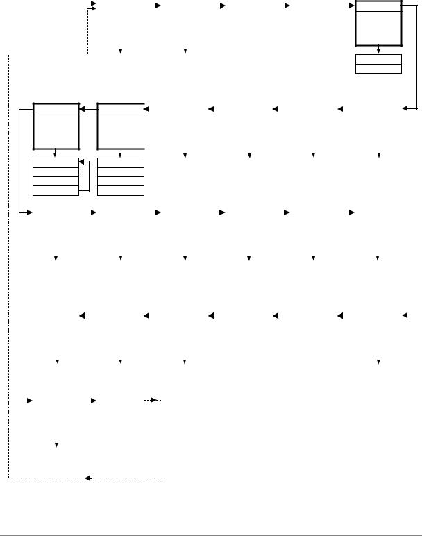
The Menu Sequence
To access the Function Menu, hold down the Menu Step button and press the Menu Set button. (The Menu Step button corresponds to the selected input - LED bright or flashing.)
To step through the Menu items, press the Menu Step button repeatedly. To select an item or one of its options, press the Menu Set button.
Use Menu Up and Menu Down buttons to alter RS232 address, Tone Level and Tone Frequency. To exit the Function Menu, either select the End item or wait five seconds.
Func |
|
|
Issue |
|
|
DSD |
|
|
Test |
|
|
Data |
|
||
|
|
|
|
|
|
|
|
|
|||||||
|
|
|
|
|
|
|
|
|
|||||||
Opens the |
|
|
Displays the |
|
|
Selects DSD |
|
|
Runs a display |
|
|
Displays the |
|
||
|
|
fitted software |
|
|
|
|
and DSP self |
|
|
message data - |
|
||||
Function Menu |
|
|
|
|
mode |
|
|
|
|
|
|||||
|
|
issue number |
|
|
|
|
test routine |
|
|
see manual |
|
||||
|
|
|
|
|
|
|
|
|
|
|
|
||||
|
|
|
|
|
|
|
|
|
|
|
|
|
|
|
|
|
|
|
|
|
|
|
|
|
|
|
|
|
|
|
|
|
|
|
|
|
|
|
|
|
|
|
|
|
|
|
|
|
|
|
v 1.5x |
|
|
Off |
|
|
|
|
|
|
|
||
|
|
|
|
|
|
|
On |
|
|
|
|
|
|
|
|
|
|
|
|
|
|
|
DSD3 |
|
|
|
|
|
|
|
|
|
|
|
|
|
|
|
DSD4 |
|
|
|
|
|
|
|
|
7 - Seg
Disables the 7- segment display when idle.
On
Off
Tone
Turns on and sets a test tone
Level (dB)
Freq (kHz)
On / Off
Up
Ref In |
|
|
RS232 |
|
|
A-Sel |
|
|
A-Cut |
|
|
Heat |
|||||
|
|
|
|
|
|
|
|
||||||||||
Sets the mode |
|
|
Displays and |
|
|
Enables |
|
|
Controls the |
|
|
Displays the |
|||||
of the AES Ref |
|
|
sets the unit's |
|
|
automatic input |
|
|
automatic |
|
|
internal |
|||||
I/O connectors |
|
|
RS232 address |
|
|
selection |
|
|
muting |
|
|
temperature |
|||||
|
|
|
|
|
|
|
|
|
|
|
|
|
|
|
|
|
|
|
|
|
|
|
|
|
|
|
|
|
|
|
|
|
|
|
|
|
|
|
|
|
|
|
|
|
|
|
|
|
|
|
|
|
|
Route |
|
|
0 ... 99 |
|
|
On |
|
|
On |
|
|
Fahrenheit |
|||||
Loop |
|
|
|
|
|
|
Off |
|
|
Off |
|
|
Celsius |
||||
Loop.t |
|
|
|
|
|
|
|
|
|
|
|
|
|
|
|
|
|
DDC |
|
|
|
|
|
|
|
|
|
|
|
|
|
|
|
|
|
|
|
Sys |
|
|
|
I-For |
|
|
|
Filt |
|
|
|
BNC I |
|
|
|
BNC |
|
|
|
BNC O |
|
|
||||||
|
|
|
|
|
|
|
|
|
|
|
|
|
|
|
|
|
|
|
||||||||||||
|
|
Turns on a full |
|
|
|
Sets the AES |
|
|
|
Selects an |
|
|
|
Sets the format |
|
|
|
Sets the mode |
|
|
|
Sets the mode |
|
|
||||||
|
|
scale system |
|
|
|
input multiwire |
|
|
|
alternative anti- |
|
|
|
of the 75R In |
|
|
|
of the BNC |
|
|
|
of the 75R Out |
|
|
||||||
|
|
test signal |
|
|
|
format |
|
|
|
alias filter |
|
|
|
connectors |
|
|
|
button |
|
|
|
connector |
|
|
||||||
|
|
|
|
|
|
|
|
|
|
|
|
|
|
|
|
|
|
|
|
|
|
|
|
|
|
|
|
|
|
|
|
|
|
|
|
|
|
|
|
|
|
|
|
|
|
|
|
|
|
|
|
|
|
|
|
|
|
|
|
|
|
|
|
|
|
|
|
|
|
|
|
|
|
|
|
|
|
|
|
|
|
|
|
|
|
|
|
|
|
|
|
|
|
|
Off |
|
|
|
Auto |
|
|
|
Filt 1 |
|
|
|
SDIF |
|
|
|
Input |
|
|
|
SDIF (WC) |
|
|
||||||
|
|
Sys - On |
|
|
|
US[1] |
|
|
|
Filt 2 |
|
|
|
AES |
|
|
|
RefCl |
|
|
|
AES |
|
|
||||||
|
CAUTION! LOUD! |
US[2] |
|
|
|
… |
|
|
|
|
|
|
|
|
|
|
|
|
|
|
|
|
|
|||||||
|
|
|
|
|
|
|
US[4] |
|
|
|
Filt n |
|
|
|
|
|
|
|
|
|
|
|
|
|
|
|
|
|
||
|
|
|
|
|
|
|
|
|
|
|
|
|
|
|
|
|
|
|
|
|
|
|
|
|
|
|
|
|
|
|
|
|
Flip |
|
|
|
S - No |
|
|
|
Part |
|
|
|
Facs |
|
|
|
Phone |
|
|
|
Panel |
|
|
||||||
|
|
|
|
|
|
|
|
|
|
|
|
|
|
|
|
|
|
|
||||||||||||
|
|
Digitally swaps |
|
|
|
Displays the |
|
|
|
Displays the |
|
|
|
Displays dCS |
|
|
|
Displays dCS |
|
|
|
Sets Phase & |
|
|
||||||
|
|
Left and Right |
|
|
|
control PCB |
|
|
|
control PCB |
|
|
|
|
|
|
telephone |
|
|
|
De-Emphasis to |
|
|
|||||||
|
|
|
|
|
|
|
|
|
|
|
fax number |
|
|
|
|
|
|
|
|
|||||||||||
|
|
outputs |
|
|
|
serial number |
|
|
|
part number |
|
|
|
|
|
|
number |
|
|
|
control Volume |
|
|
|||||||
|
|
|
|
|
|
|
|
|
|
|
|
|
|
|
|
|
|
|
|
|
||||||||||
|
|
|
|
|
|
|
|
|
|
|
|
|
|
|
|
|
|
|
|
|
|
|
|
|
|
|
|
|
|
|
|
|
|
|
|
|
|
|
|
|
|
|
|
|
|
|
|
|
|
|
|
|
|
|
|
|
|
|
|
||
|
|
|
|
|
|
|
|
|
|
|
|
|
|
|
|
|
|
|
|
|
|
|
|
|
|
|
|
|
|
|
|
|
Off |
|
|
|
0002-540-?-? |
|
|
|
dCS002540? |
|
|
|
|
|
|
|
|
|
|
|
|
|
Phase |
|
|
||||
|
|
On |
|
|
|
|
|
|
|
|
|
|
|
|
|
|
|
|
|
|
|
|
|
|
|
Vol |
|
|
||
|
|
|
|
|
|
|
|
|
|
|
|
|
|
|
|
|
|
|
|
|
|
|
|
|
|
|
|
|
|
|
|
|
Loc |
|
|
|
End |
|
|
|
|
|
|
|
|
|
|
|
|
|
|
|
|
|
|
|
|
|
|
||
|
|
|
|
|
|
|
|
|
|
|
|
|
|
|
|
|
|
|
|
|
|
|
|
|
|
|
||||
|
|
Locks out the |
|
|
|
Exits the |
|
|
|
|
|
|
|
|
|
|
|
|
|
|
|
|
|
|
|
|
|
|
||
|
|
front panel |
|
|
|
|
|
|
|
|
|
|
|
|
|
|
|
|
|
|
|
|
|
|
|
|
|
|||
|
|
|
|
|
Function Menu |
|
|
|
|
|
|
|
|
|
|
|
|
|
|
|
|
|
|
|
|
|
|
|||
|
|
controls |
|
|
|
|
|
|
|
|
|
|
|
|
|
|
|
|
|
|
|
|
|
|
|
|
|
|||
|
|
|
|
|
|
|
|
|
|
|
|
|
|
|
|
|
|
|
|
|
|
|
|
|
|
|
|
|
||
|
|
|
|
|
|
|
|
|
|
|
|
|
|
|
|
|
Please note that DDC mode turns off the analogue outputs. |
|
|
|||||||||||
|
|
|
|
|
|
|
|
|
|
|
|
|
|
|
|
|
|
|
||||||||||||
|
|
|
|
|
|
|
|
|
|
|
|
|
|
|
|
|
|
|
||||||||||||
|
|
Off |
|
|
|
|
|
|
|
|
|
|
|
|
|
Some features are not available in DSD mode. |
|
|
|
|
||||||||||
|
|
On |
|
|
|
|
|
|
|
|
|
|
|
|
|
P3D mode is only available on some hardware configurations. |
|
|
||||||||||||
Standard software v1.5x
P3D software v1.36
Figure 4 – Menu Sequence
Manual part no: DOC136954 iss 2B1 |
Page 19 |
file 135954ma2b1.pdf available from website |
Contact dCS on + 44 1799 531 999 |
email to: more@dcsltd.co.uk |
(inside the UK replace + 44 with 0) |
web site: www.dcsltd.co.uk |

dCS 954 User Manual |
Manual for Standard Software Version 1.5x |
dCS Ltd |
June 2000 |
|
|
Menu Items
Issue
Displays the software issue when Set is pressed.
DSD
Selects DSD mode. When on and locked, the unit displays “dSd”. This mode takes about 15 seconds to load, during which time the menu cannot be used. There are two options:
Off |
The unit operates in PCM mode. |
On |
The unit will accept either DSD via the SDIF input |
|
connectors (automatically selecting SDIF-2 or |
|
SDIF-3 format) or DSD packed into 4 AES3 |
|
44.1kS/s links. |
P3D units have a slightly more explicit menu sequence for this item:
Off |
The unit operates in PCM mode. |
P3D |
The unit will accept DSD via the SDIF input |
|
connectors (automatically selecting SDIF-2 or |
|
SDIF-3 format) or DSD packed in P3D format on |
|
connectors AES1-3 |
DSD4 |
The unit will accept DSD via the SDIF input |
|
connectors (automatically selecting SDIF-2 or |
|
SDIF-3 format) or DSD packed into 4 AES3 |
|
44.1kS/s links. |
To select DSD on the SDIF inputs, first set the dSd menu option to On. Connect the 2 data lines plus a 44.1kS/s Word Clock and press the BNC button. The LED above the button will brighten and the display will show dSd.
To select 4-wire DSD mode, first set the dSd menu option to On. Connect the four-wire encoded DSD 44.1kS/s data streams to the AES1 – 4 inputs, taking care to ensure they are in the correct order, and press the AES1 button. The 4 LEDs above the buttons will brighten, the unit will display dSd and unmute. The unit detects swapped or missing wires by displaying (for example) 1324 or 1-34.
DSD is so different from PCM that many of the PCM related features are no longer appropriate or are not implemented.
-the Mute and Coarse Lock buttons operate as usual
-the Phase and De-Emphasis buttons do not work and
-the Volume control is disabled.
-the following Menu items are disabled or have their functions locked: Data, A-Cut, A-Sel, Tone, Sys, I-For, BNC I, BNC, BNC O, Panel and Flip.
Filt works – there are 4 filter options in DSD mode. See the section on “DSD” starting on page 40 for more details – they trade-off ultrasonic signal bandwidth and out-of-band noise. A-Cut is set to On, as DSD data in multi-wire AES formats should be flagged as Non-Audio. The Ref In option is disabled in SDIF DSD mode.
Manual part no: DOC136954 iss 2B1 |
Page 20 |
file 135954ma2b1.pdf available from website |
Contact dCS on + 44 1799 531 999 |
email to: more@dcsltd.co.uk |
(inside the UK replace + 44 with 0) |
web site: www.dcsltd.co.uk |
dCS 954 User Manual |
Manual for Standard Software Version 1.5x |
dCS Ltd |
June 2000 |
IMPORTANT! If the Non Audio flag is stripped by the recorder and the dCS 954 is not set to DSD mode, it will accept DSD data as AES3 PCM and will output potentially damaging full scale noise.
If you connect DSD to the SDIF input and select it while DSD mode is Off, the unit will remain muted, identify the format, automatically select DSD mode and unmute.
If you connect SDIF while DSD mode is On, the unit will remain muted until you set DSD mode to Off.
To use P3D mode (assuming your hardware is suitable), first set the DSD menu option to dSd3. Connect the three-wire encoded DSD 44.1kS/s data streams to the AES1-3 inputs taking care to ensure they are in the correct order, and press the AES1 button. The 3 LEDs above the buttons will brighten and the display will show dSd. Contact dCS for further details.
Test
Runs a display self test routine. When successfully completed, the unit displays Pass and returns to normal operation. Otherwise an error message Err.xy is displayed – please refer to “Error Codes and Messages” on page 76 for more specific information.
Data
Reads and displays the message information from an incoming AES/EBU data stream. This provides a simple access to the digital audio message bits for reference or to assist with system debugging. There are separate data sets for Professional and Consumer streams - the unit reads the incoming stream and decides which it is. Pressing Set again steps through the message fields (see the Appendix for a fuller listing of what these are):
First field |
Professional use channel status block, or ... |
|
Pro |
||
Con |
Consumer use channel status block. |
|
Second field |
Audio data, or ... |
|
Audio |
|
|
n.Aud |
Non-audio data. |
|
Third field |
Emphasis not indicated, or... |
|
N Ind |
||
None |
No emphasis, or ... |
|
50 15 |
50/15 s emphasis, or ... |
|
J. 17 |
CCITT J.17 emphasis, or ... |
|
D ---- |
Unable to decode emphasis, or ... |
|
CPY P |
Copy prohibit, or ... |
|
CPY E |
Copy enable. |
|
Fourth field |
Encoded sample rate is “xxxx”, i.e. 32, 44.1, 48, |
|
Exxxx |
||
|
88.2, 96, 176.4 0r 192kS/s. Non-dCS equipment |
|
|
may only decode the first 3 options. or ... |
|
E---- |
Unknown encoded sample rate. |
|
Fifth field |
|
|
|
|
|
Manual part no: DOC136954 iss 2B1 |
Page 21 |
file 135954ma2b1.pdf available from website |
Contact dCS on + 44 1799 531 999 |
email to: more@dcsltd.co.uk |
(inside the UK replace + 44 with 0) |
web site: www.dcsltd.co.uk |

dCS 954 User Manual |
Manual for Standard Software Version 1.5x |
dCS Ltd |
June 2000 |
|
|
O.xxxx |
Channel origin (alphanumeric), or ... |
NonE |
Emphasis not indicated, or... |
50 15 |
50/15 s emphasis, or ... |
D ---- |
Unable to decode emphasis. |
Sixth field |
Channel destination (alphanumeric), or ... |
D.xxxx |
|
Cd |
CD source, or ... |
Enc |
2-channel encoder / decoder, or ... |
dAt |
DAT machine, or ... |
S---- |
Unknown source. |
7-Seg
Disables the main 7 segment LED display. When set to Off, the Sample Rate display turns off 5 seconds after the last button press. A dot in the lower right hand corner of the display remains lit to indicate that the display has been deliberately blanked. The display springs back into life (temporarily) if the menu is used subsequently. Error or warning messages are displayed regardless of this setting. The Mode display is not affected.
Heat
Displays the internal temperature of the unit. Press Set to toggle between Fahrenheit and Celsius.
A-Cut
Automatically mutes the analogue outputs if the selected AES/EBU data stream is flagged as Non Audio. This gives useful protection and should normally be set to On. Set to Off to disable Auto-Muting. To warn you of this, the Mute LED will flash when the unit is not muted.
IMPORTANT! Auto-Muting should not be disabled unless absolutely necessary as this will prevent the unit muting if data errors occur or a non-audio CD is played. Monitoring such data can cause loudspeaker and hearing damage!
A-Sel
When set to On, automatic input selection is active. The unit will detect the inputs connected to an active source and select one in the priority order AES1, AES2, AES3, AES4, BNC. If the selected input is disconnected or turned off, the unit will select the active input with the highest priority. You can select a different input by pressing the appropriate button.
You might wish to use this function when a main signal is being fed into one input, with a backup signal from another source being fed into a different input. If the main signal fails, the unit will automatically switch to the backup. Or, if you wish the dCS 954 to just play whatever you plug into it, and not worry about which input you are using, you might wish to set A-Sel to On.
If the I-For menu item (“Input Format”, see page 25) is set to Auto, the unit will read the multi-wire format from the message flags in the AES3 data streams, selecting Dual or Quad AES groups as necessary. If the message flags are incorrectly set, the unit may set the wrong multi-wire format.
Manual part no: DOC136954 iss 2B1 |
Page 22 |
file 135954ma2b1.pdf available from website |
Contact dCS on + 44 1799 531 999 |
email to: more@dcsltd.co.uk |
(inside the UK replace + 44 with 0) |
web site: www.dcsltd.co.uk |

dCS 954 User Manual |
Manual for Standard Software Version 1.5x |
dCS Ltd |
June 2000 |
If the input format is set to Single, Dual or Quad AES format, the unit will ignore the message flags and group the AES inputs accordingly.
Set A-Sel to Off to disable automatic input selection.
RS232
Displays - and allows access to – the unit’s RS-232 identity code (an address between 0 and 99). This is used by the remote control software to send specific messages to specific units. Use Up and Down to change this address if you are operating several units in a multichannel set up. The RS-232 control formats and procedures are covered in more detail in section “RS-232 Remote Control Interface” starting on page 56
IMPORTANT! When using the Remote Control, each unit in the daisy chain MUST be set to a different RS-232 address.
Ref In
Displays and sets the mode of the AES Reference In/Out connectors. The options are:
Route |
Reference Out (connected in parallel with |
|
Reference In – beware!) is internally driven with |
|
the selected AES input signal. |
|
If the input is Dual or Quad AES, the data on the |
|
lowest of AES1 or AES3 appears on Reference |
|
Out. |
|
If BNC is selected, there is no output. |
Loop |
The unit attempts to lock to Reference In, which is |
|
looped through to the Reference Out, with no |
|
termination resistor (termination is then about 1kΩ, |
|
so several units can be daisy chained). |
Loop.t |
As above, but terminates the input to achieve |
|
110Ω. Use at the end of a daisy chain. |
ddC |
Converts the data on the selected input to single |
|
AES and sends it to Reference Out. |
|
The data on a Single AES input is copied with no |
|
conversion. |
|
The data on a Dual or Quad AES input is converted |
|
to Double speed Single AES. 176.4kS/s is |
|
converted to 88.2kS/s and 192kS/s is converted to |
|
96kS/s. |
|
If BNC in SDIF mode is selected, the output is AES |
|
clock with no data at the Word Clock rate. |
|
If the input is 4-wire DSD, the data is converted to |
|
SDIF format DSD and sent to the SDIF inputs. |
|
SDIF Ch1 is checked first before the SDIF inputs |
|
are changed to DSD outputs. |
IMPORTANT! In DDC mode, the analogue outputs are generally muted because the units resources are used to perform a digital to digital conversion. They are not muted if the input is 4-wire DSD.
Manual part no: DOC136954 iss 2B1 |
Page 23 |
file 135954ma2b1.pdf available from website |
Contact dCS on + 44 1799 531 999 |
email to: more@dcsltd.co.uk |
(inside the UK replace + 44 with 0) |
web site: www.dcsltd.co.uk |

dCS 954 User Manual |
Manual for Standard Software Version 1.5x |
dCS Ltd |
June 2000 |
Tone
(Tone Generator). This controls an internal Tone Generator, whose level and frequency can be adjusted. Pressing Set enters a submenu, which accesses the following functions:
Level |
The output level in dB0. It can be changed in 0.1dB |
|||||||||||
|
steps using the |
Up |
and |
Down |
buttons. Press |
Set |
||||||
|
to accept the |
|
change. |
|
The |
rate of change |
||||||
|
accelerates if the button is held down. The range is |
|||||||||||
|
from 0dB0 to –120dB0. |
|||||||||||
Freq |
The output frequency, in kHz. It can be changed by |
|||||||||||
|
using the |
Up |
and |
Down |
buttons. Press |
Set |
to |
|||||
|
accept the |
change. The rate of change accelerates |
||||||||||
|
if the button is held down. The step size becomes |
|||||||||||
|
progressively smaller below 1kHz. |
|||||||||||
On/Off |
Toggles whether the Generator is on or off. |
|||||||||||
Up |
Allows the menu to be re-entered to set other |
|||||||||||
|
functions. Alternatively, if left, the menu will just |
|||||||||||
|
time out, keeping the last settings. |
|||||||||||
The frequency range is from 1Hz to 99kHz but the level rolls off at the extremes, due to anti-image filters in the analogue circuitry. The Generator output level is within –0.1dB from less than 10Hz up to 50kHz.
The Tone Generator works standalone, without a digital input. If locked, the unit will be unlocked when the Generator is turned on. At power up, the Generator is always set to Off, 1kHz and –18dB0 – this is a safety measure.
If very fine frequency resolution is wanted, RS-232 control will give mHz frequency resolution. See section “RS-232 Remote Control Interface” starting on page 56.
The tone generator is very pure – it is a good analogue source.
IMPORTANT! To avoid damage to your ears, loudspeakers and power amplifiers, use the Tone Generator with care .
Sys
System phase check. This turns on a full-scale test signal for checking absolute output phase on an oscilloscope.
IMPORTANT! To avoid damage to your ears, loudspeakers and power amplifiers, use the Sys option with care . Turn your system volume level well down before using this feature!
Turn this option On, the display will flash Sys On and the waveforms shown below will appear on the analogue outputs. The top waveform is from the left channel, the bottom is from the right.
Manual part no: DOC136954 iss 2B1 |
Page 24 |
file 135954ma2b1.pdf available from website |
Contact dCS on + 44 1799 531 999 |
email to: more@dcsltd.co.uk |
(inside the UK replace + 44 with 0) |
web site: www.dcsltd.co.uk |

dCS 954 User Manual |
Manual for Standard Software Version 1.5x |
dCS Ltd |
June 2000 |
|
|
Figure 5 – In-phase Sys waveform
Referring to Figure 5, if the triangular sections point up, that channel is in phase. A triangular section pointing up with a rectangular block on its left side indicates left channel. A rectangular block on the right indicates right channel.
Figure 6 shows the waveforms with both channels inverted.
Figure 6 – Out-of-phase Sys waveform
These waveforms are not affected by the setting of the Phase button.
Set Sys to Off when you have finished checking. Sys is turned off at power down.
Manual part no: DOC136954 iss 2B1 |
Page 25 |
file 135954ma2b1.pdf available from website |
Contact dCS on + 44 1799 531 999 |
email to: more@dcsltd.co.uk |
(inside the UK replace + 44 with 0) |
web site: www.dcsltd.co.uk |

dCS 954 User Manual |
Manual for Standard Software Version 1.5x |
dCS Ltd |
June 2000 |
|
|
I-For
(Input Format). Sets the AES input multi-wire format Input Format. There are 4 options:
Auto |
The message flags on the selected input are |
|
checked and the format is automatically set to |
|
Single, Dual or Quad AES. Dual AES must be |
|
connected to AES 1 & 2 or AES 3 & 4. |
US[1] |
User-selected Single AES mode. |
US[2] |
User-selected Dual AES mode. |
US[4] |
User selected Quad AES mode. |
You can over-ride any setting using the AES1 – AES4 buttons.
In Dual or Quad AES modes, the unit will warn you of missing wires with a display like 1-34 (AES2 not connected for Quad AES). Swapped wires causes a display like 1243 (AES3 & 4 swapped). The checking relies on correct messaging and may not work with non-dCS equipment.
Filt
(Filter). Selects one of several anti-image3 filter responses. The filters should be evaluated by ear. Filt1 gives the sharpest cut off, just below half the sampling frequency. This is the normal setting. Filt2, Filt3, Filt4 give progressively more relaxed responses, slightly degrading the Nyquist image performance but sharpening the impulse response. This affects the stereo or multi-channel image. Different filters may be appropriate for different material.
A typical audio signal contains very little signal energy above 10kHz, so there is some justification for relaxing the filter attenuation as 20kHz is approached.
DSD mode also has four filters. Metering DSD is difficult because the high level of ultrasonic noise can cause spurious meter readings. DSD Filt4 is specially designed for metering the 0 – 20kHz band and may not give the best sonic performance.
BNC I
(BNC Inputs). In PCM mode, this sets the format of the BNC In connectors.
SDIF |
Configures Ch1, Ch2 and Clk In as an SDIF-2 |
|
interface. |
AES |
Configures Clk In to accept AES3 encoded data at |
|
TTL levels at up to 96kS/s. |
Select these inputs using the BNC button.
If the unit is already locked to SDIF or DSD, the AES option is disabled.
3Nyquist images, not stereo images. These are reflections of the pass-band spectrum about Fs/2 caused by any digital-to-analogue conversion process. They must be filtered out by the converter.
Manual part no: DOC136954 iss 2B1 |
Page 26 |
file 135954ma2b1.pdf available from website |
Contact dCS on + 44 1799 531 999 |
email to: more@dcsltd.co.uk |
(inside the UK replace + 44 with 0) |
web site: www.dcsltd.co.uk |

dCS 954 User Manual |
Manual for Standard Software Version 1.5x |
dCS Ltd |
June 2000 |
|
|
BNC
(BNC Button). In PCM mode, this controls the operation of the BNC button.
Input |
Configures the BNC input connectors as a data |
|
input. Press the BNC button to select it. |
RefCl |
Configures the BNC word clock in (Clk In) |
|
connector as a reference clock input. Press the |
|
BNC button to sync the unit to the Word clock |
|
while taking data from one or more of the AES |
|
inputs. The BNC LED will light, in addition to the |
|
LED(s) for the data source. Press the BNC button |
|
again to sync to the data input instead. |
This mode of operation enable the unit to sync to one clock source and rapidly switch between other synchronous sources without going through a PLL locking sequence. It might be used, for example, in A/B comparisons or in locking to a house sync, just taking data from AES feeds.
If the unit is already locked to SDIF or DSD, the RefCl option is disabled.
BNC O
(BNC Output). In PCM mode, this sets the format of the BNC Out connector (Clk Out).
SDIF |
Sends out SDIF Word Clock on the Clk Out |
|
connector. The unit must be locked to generate an |
|
output. |
AES |
Sends out AES3 coded data at TTL levels, at up to |
|
96 kS/s on the Clk Out connector. This works |
|
when the unit is locked to Single AES, SDIF or |
|
BNC - AES input. |
Panel |
|
(Panel Control). Sets the operation of the Phase and De-Emphasis buttons. |
|
Phase |
Sets the two buttons to their standard functions. |
Vol |
The two buttons act as a digital volume control. |
|
Phase reduces the Volume in 0.1dB steps, while |
De-Emphasis increases the Volume. The change accelerates if a button is held down. The range is 0dB to –20dB.
Phone
dCS telephone number scrolls across the display.
Facs
dCS fax number scrolls across the display
Part
The control board part number (version) scrolls along the display.
Manual part no: DOC136954 iss 2B1 |
Page 27 |
file 135954ma2b1.pdf available from website |
Contact dCS on + 44 1799 531 999 |
email to: more@dcsltd.co.uk |
(inside the UK replace + 44 with 0) |
web site: www.dcsltd.co.uk |
 Loading...