


DCS 500 Thyristor Power Converters for DC Drive Systems 25 to 5150 A
Operating Instructions
DCS 500B / DCF 500B
DCP 500B

Volume II D
System Description
DCS 500B 3ADW000066
Volume III
Technical Data
3ADW000054
Volume IV D
Operating Instructions
DCS 500B 3ADW000055
How the DCS 500 Documentation System works
Description of the converter
DCS 500B Operating Instructions
(documentation in hand) including information and advise to commission the drive. If three phase DCF 500B field supply units are needed please use the same documents as for DCS 500B armature converters.
As additional documentation is available:
The System description describes the functionality of DCS 500 converter units as well as the cooperation of all single components belonging to a complete drive system.
DCS 500 Technical Data giving information about all direct technical data for components used inside and outside the converter module.
The above mentioned documents are usually delivered together with all ordered converter units of the DCS 500 family and represent the basic knowledge which is essential for all users of this product.
Volume II D1
System Description
DCA 500B 3ADW000148
Volume V D2
Application Blocks
DCS 500B
3ADW000048
Volume V D1
SW Description
DCS 500B
3ADW000078
Volume VII A
Technical Guide
DCS
3ADW000163
Volume VI A
Service Manual
DCS 500(B)/600
3ADW000093
Supplementary documentation
DCA 500 System description for standard cubicles equipped with DC drives.
For those, who want to reprogram or adapt the software of their drive a detailed comprehensive description of the software structure of the drive as well as of all available function blocks can be delivered. This documentation is only available as data file in English language.
As separate document for service engineers a DCS 500 Service Manual can be ordered .
Engineering and design people for drive systems can get a separate collection of information with regard to installation, sizing, fusing etc. of DC drives called "Technical guide".
3ADW000055R0401_DCS500B_Operating Instruction_e_d
Thyristor Power Converters
Series
DCS 500B / DCF 500B DCP 500B
25 to 5150 A
OPERATING INSTRUCTIONS
Code: 3ADW 000 055 R0401 Rev D
|
DCS_OI_E_D.DOC |
EFFECTIVE: |
Oct. 30th, 2002 |
SUPERSEDES:Rev C Sept. 14th, 2001
2002 ABB Automation Products GmbH. All rights reserved.
3ADW000055R0401_DCS500B_Operating Instruction_e_d

DCS 500B / DCP 500B Operating Instructions
3ADW000055R0401_DCS500B_Operating Instruction_e_d
Safety Instructions
Overview |
This chapter contains safety instructions which must be complied |
|
with during installation, operation and maintenance of the power |
|
converters series DCS 500B / DCF 500B or DCP 500B. If these in- |
|
structions are not complied with, this may result in injuries (perhaps |
|
even with fatal) or in damage to the power converter, the motor and |
|
the driven machine. Before starting with any work whatsoever at or |
|
with this unit, you must read the information given in this chapter. |
Warnings |
Warnings provide information on states which if the specified pro- |
|
cedure for the state concerned is not meticulously complied with |
|
may result in a serious error, in major damage to the unit, in injury |
|
to persons and even in death. |
|
They are identified by the following symbols: |
|
|
|
Danger: High Voltage! This symbol warns you of |
|
high voltages which may result in injuries to persons |
|
and/or damage to equipment. Where appropriate, the |
|
text printed adjacent to this symbol describes how |
|
risks of this kind may be avoided. |
|
|
|
● All electrical installation and maintenance work on the thyristor |
|
power converter must be carried out by properly qualified staff |
|
who have been thoroughly trained in electrical engineering. |
|
● The thyristor power converter and its adjacent units must be |
|
properly earthed by qualified professionals. |
|
● You must NEVER perform any work on the thyristor power con- |
|
verter while it is still switched on. First switch the unit off, use a |
|
measuring instrument to make absolutely sure that the power |
|
converter has really been de-energized, and only then you may |
|
start with the work concerned. |
|
● Due to external control circuits, there may be dangerously high |
|
voltages present at the thyristor power converter even after the |
|
line voltage has been switched off. So always work at the unit |
|
with appropriate caution! Non-compliance with these instructions |
|
may result in injury (or even death!). |
DCS 500B / DCP 500B Operating Instructions |
i |
3ADW000055R0401_DCS500B_Operating Instruction_e_d
Safety Instructions
General warning: this symbol warns you of nonelectrical risks and dangers which may result in serious or even fatal injury to persons and/or in damage to equipment. Where appropriate, the text printed adjacent to this symbol describes how risks of this kind may be avoided.
●When thyristor power converters are in use, the electric motors, power transmission elements and the driven machines are working in an extended operating range, which means they have to cope with a relatively high loading.
●You should have made sure that all units, devices and appliances used are actually suitable for this higher loading.
●If you have to operate the thyristor power converter at a rated motor voltage and/or a rated motor current significantly below the figures stated in the thyristor power converter's output data, you must take appropriate precautionary measures to protect the unit against overspeed, overload, breakage, etc., by modifying the software or hardware appropriately.
●For insulation testing, you must disconnect all cables from the thyristor power converter. You should avoid operating your unit at values other than the rated data. Non-compliance with these instructions may cause lasting damage to the thyristor power converter.
●The thyristor power converter possesses a number of automatic reset functions. When these functions are executed, the unit will be reset after an error and will then resume operation. These functions should not be used if other units and devices are not suitable for an operating mode of this kind, or if their use might entail dangerous situations.
Warning of electrostatic discharge:
this symbol warns you against electrostatic discharges which may damage the unit. Where appropriate, the text printed next to this symbol describes how a risk of this kind may be avoided.
ii |
DCS 500B / DCP 500B Operating Instructions |
3ADW000055R0401_DCS500B_Operating Instruction_e_d

Notes
Mains connection
EMERGENCY STOP buttons
Intended use
Safety Instructions
Notes supply information on states requiring particular attention, or indicate that additional information is available on a specific topic. For this purpose, the following symbols are used:
CAUTION! Cautions are designed to draw your attention to a particular state of affairs.
Note |
A note contains or refers you to additional informa- |
|
tion available on the particular topic concerned. |
You can use a switch disconnector (with fuses) in the power supply of the thyristor power converter to disconnect the electrical components of the unit from the power supply for installation and maintenance work. The type of disconnector used must be a switch disconnector as per EN 60947-3, Class B, so as to comply with EU regulations, or a circuit-breaker type which switches off the load circuit by means of an auxiliary contact causing the breaker's main contacts to open. The mains disconnector must be locked in its "OPEN" position during any installation and maintenance work.
EMERGENCY STOP buttons must be installed at each control desk and at all other control panels requiring an emergency stop function. Pressing the STOP button on the CDP 31x control panel of the thyristor power converter will neither cause an emergency motor stop, nor will the drive be disconnected from any dangerous potential.
The operating instructions cannot take into consideration every possible case of configuration, operation or maintenance. Thus, they mainly give such advice only, which is required by qualified personnel for normal operation of the machines and devices in industrial installations.
If in special cases the electrical machines and devices are intended for use in non-industrial installations - which may require stricter safety regulations (e.g. protection against contact by
children or similar) -, these additional safety measures for the installation must be provided by the customer during assembly.
DCS 500B / DCP 500B Operating Instructions |
iii |
3ADW000055R0401_DCS500B_Operating Instruction_e_d

Contents
IV A OPERATING INSTRUCTIONS
Safety Instructions |
|
|
Chapter 1 - Introduction |
|
|
How to use this manual ........................................................................................................... |
1-1 |
|
Contents of this manual........................................................................................................... |
1-1 |
|
Target group ............................................................................................................................ |
1-1 |
|
Associated publications .......................................................................................................... |
1-1 |
|
Incoming inspection................................................................................................................. |
1-2 |
|
Storage and transport.............................................................................................................. |
1-2 |
|
Rating plate ............................................................................................................................. |
1-2 |
|
Chapter 2 - Start-Up Instructions |
|
|
General notes .......................................................................................................................... |
2-1 |
|
2.1 |
Preparatory work ............................................................................................................... |
2-5 |
2.2 |
Scaling intra-unit signals.................................................................................................... |
2-6 |
2.3 |
Presetting the field supply unit........................................................................................... |
2-8 |
2.4 |
Adjusting the current controller........................................................................................ |
2-10 |
2.5 |
Speed feedback balancing .............................................................................................. |
2-12 |
2.6 |
Balancing the field supply unit and the e.m.f. controller .................................................. |
2-14 |
2.7 |
Balancing the speed controller, plus fine-balancing the e.m.f. and the current contr...... |
2-20 |
2.8 |
Matching the thyristor power converter unit to the system conditions concerned ........... |
2-21 |
2.9 |
Presetting the 3-phase field supply unit DCF 50xB ......................................................... |
2-22 |
Chapter 3 - Handling of Control Panel CDP 31x |
|
|
3.1 |
Overview............................................................................................................................ |
3-1 |
|
Panel Link .................................................................................................................... |
3-1 |
|
Mounting the Panel ..................................................................................................... |
3-1 |
3.2 |
Start Mode ......................................................................................................................... |
3-2 |
3.3 |
Panel Functions................................................................................................................. |
3-3 |
|
Actual Signal Display Mode ......................................................................................... |
3-3 |
|
Parameter Mode .......................................................................................................... |
3-4 |
|
Function Mode ............................................................................................................. |
3-4 |
|
Drive Mode................................................................................................................... |
3-5 |
3.4 |
Pin/Parameter Selecting and Changing of Value .............................................................. |
3-5 |
3.5 |
Saving of the Parameters to backup memory ................................................................... |
3-7 |
3.6 FAULT RESETTING (RESET) .......................................................................................... |
3-8 |
|
3.7 EMERGENCY STOP RESETTING (RESET).................................................................... |
3-8 |
|
3.8 |
Fault History Display.......................................................................................................... |
3-9 |
3.9 |
Uploading and Downloading of Parameters (UPLOAD/DOWNLOAD)............................ |
3-10 |
3.10 Setting of the Display Contrast ...................................................................................... |
3-12 |
|
3.11 Full Name of output pins................................................................................................ |
3-12 |
|
3.12 Selecting output pins ..................................................................................................... |
3-13 |
|
3.13 Drive Mode .................................................................................................................... |
3-14 |
|
3.14 Running the Drive.......................................................................................................... |
3-15 |
|
|
Operational Command Keys...................................................................................... |
3-15 |
|
|
|
iv |
DCS 500B / DCP 500B Operating Instructions |
|
3ADW000055R0401_DCS500B_Operating Instruction_e_d

|
Contents |
Running the DCDrive from the CDP31x |
................................................................. 3-15 |
3.15 Speed Reference Setting for the Drive.......................................................................... |
3-16 |
Chapter 4 - Signals and Troubleshooting
4.1 |
Display of status, alarm and fault signals .......................................................................... |
4-1 |
|
Categories of signals and possibilities of display......................................................... |
4-1 |
4.2 |
General messages ............................................................................................................ |
4-2 |
4.3 |
Starting errors (E).............................................................................................................. |
4-2 |
4.4 |
Fault Signals (F) ................................................................................................................ |
4-3 |
4.5 |
Alarm Signals (A) ............................................................................................................ |
4-12 |
4.6 |
Status Signals ................................................................................................................. |
4-17 |
Appendix A - Connection diagrams |
|
|
Connection diagram 1 ............................................................................................................. |
A-1 |
|
Connection diagram 2 ............................................................................................................. |
A-2 |
|
DCS 500B / DCP 500B Operating Instructions |
v |
3ADW000055R0401_DCS500B_Operating Instruction_e_d

vi |
DCS 500B / DCP 500B Operating Instructions |
3ADW000055R0401_DCS500B_Operating Instruction_e_d
Chapter 1 - Introduction
How to use this manual |
The purpose of these operating instructions is to provide detailed in- |
|
formation on how to start up a thyristor power converter from the |
|
DCS 500B or DCP 500B series. |
|
Note: If it is not mentioned explicitly all details given in |
|
these Operating Instructions will be valid for both, |
|
series DCS 500B / DCF 500B and series DCP 500B! |
Contents of this manual |
Chapter 1 - Introduction |
|
It describes how to use this manual and the boundary conditions |
|
applying. |
|
Chapter 2 - Start-Up Instructions |
|
We recommend working your way through the Start-Up Instructions |
|
step by step, since in this way you will get to perform all important |
|
parameter setting routines. |
|
Chapter 3 - How to Handle the Control and Display Panel |
|
This chapter describes how to operate the CDP 31x control and |
|
display panel. |
|
Chapter 4 - Signals and Troubleshooting |
|
This chapter describes the available signals and possibilities of dis- |
|
play with DCS 500B and DCP 500B. As far as fault signals are con- |
|
cerned there will be indicated measures (actions) to be taken for |
|
troubleshooting. |
Target group |
This manual is designed to help those responsible for planning, in- |
|
stalling, starting up and servicing the thyristor power converter. |
|
These people should possess |
|
• basic knowledge of physics and electrical engineering, electrical |
|
wiring principles, components and symbols used in electrical en- |
|
gineering, and |
|
• basic experience with DC drives and products. |
Associated |
The DCS 500B / DCF 500B or DCP 500B documentation includes |
publications |
the following: |
|
• System Description DCS 500B / DCF 500B |
|
• System Description DCP 500B |
|
• Technical Data DCS 500B / DCF 500B, DCP 500B |
|
• Operating Instructions (this document) |
DCS 500B / DCP 500B Operating Instructions |
IV A 1 - 1 |
3ADW000055R0401_DCS500B_Operating Instruction_e_d

Chapter 1 - Introduction
Incoming inspection |
After opening this package, you should check whether it contains |
|
the following items: |
|
● DCS 500B / DCF 500B or DCP 500B thyristor power con- |
|
verter in the configuration ordered |
|
● DCS 500B / DCF 500B or DCP 500B publications |
|
● Accessories, including manuals if ordered |
|
● Final test report |
|
Check the consignment for any signs of damage. If you find any, |
|
please contact the insurance company or the supplier. |
|
Check the particulars given on the unit's rating plate to make sure |
|
prior to installation and start-up that you have received the correct |
|
unit type and unit version. |
|
If the consignment is incomplete or contains any incorrect items, |
|
please contact the supplier. |
|
|
|
CAUTION! The thyristor power converter weighs quite a lot and |
|
should therefore not be held by the front cover. Please put the unit |
|
down only on its back (sizes C1/C2/A5). Always use care when |
|
handling the unit, so as to avoid injuries or damage. |
Storage and transport |
|
If the unit had been in storage prior to installation or is transported |
|
|
to another location, care must be taken to ensure that the environ- |
|
mental conditions are complied with (see "System Descriptions |
|
DCS 500B / DCF 500B or DCP 500B"). |
Rating plate |
For purposes of identification, each thyristor power converter is fit- |
|
ted with rating plates, stating the type code and the serial number, |
|
which serve for each unit's individual identification. |
|
The type code contains information on the characteristics and the |
|
configuration of the unit. The first three digits of the serial number |
|
refer to the year and week of manufacture. The last digits complete |
|
the serial number so as to preclude two units receiving the same |
|
type code and the same serial number. |
|
The 112xx group provides information on the unit's software con- |
|
figuration. |
|
The technical data and specifications are valid as of going to press. |
|
ABB reserves the right to make subsequent alterations. |
|
If you have any questions concerning your drive system, please |
|
contact your local ABB agent. |
IV A 1 - 2 |
DCS 500B / DCP 500B Operating Instructions |
3ADW000055R0401_DCS500B_Operating Instruction_e_d
Chapter 2 - Start-Up Instructions
General notes
CAUTION: it is absolutely essential that the applicable accident prevention regulations be observed by the user (in this context, please also read the chapter entitled "Safety Instructions")!
How this chapter is structured
For better understanding the individual steps of start-up work are distinguished by a) frames without any additional marking on the left side:
These steps of start-up work must always be performed (= mandatory start-up work)!
Example:
522 = GERMAN [Only with the SDCS-CON-2 control board & the CDP 312 panel!]
Activates German texts on the display ...........
b) frames with marking on the left side („columns“ shaded in grey):
These steps of start-up work have to be performed only when the condition stated (as heading) applies to the selected drive configuration! After this work has been completed, the mandatory start-up work has to be continued.
Example:
Only when connection diagram 1 (Appendix A) is being used!
906 = 12502
Function „EMERGENCY STOP“ de-activated ............
Recommended motor voltages and field voltages
• Motor voltage UA when the following units are used |
|
|
DCS 501B / DCP 501B: |
UAmax = Line voltage * 1.16 |
(2- quadrant unit) |
DCS 502B / DCP 502B: |
UAmax = Line voltage * 1.05 |
(4- quadrant unit) |
• Field voltage UF (= max. output voltage) when the following is being used SDCS-FEX-1:
If there is a divergence of more than 10 % between the field supply unit's output
voltage and the rated field voltage UFrated stated on the motor's rating plate, then the connecting voltage UN should be reduced, using a matching transformer or a series
resistor Rv: Rv = (0.9 * UN - UF) / IF IF = Rated field current (Note: also suitable for fine-balancing the maximum motor voltage)
•Field voltage UF when the following is being used SDCS-FEX-2 /
DCF 503 / DCF 504:
• Field voltage UF when the following is being used DCF 501B / DCF 502B:
Maximally possible output voltage UAmax using DCF 501B / DCF 502B:
DCS 500B / DCP 500B Operating Instructions |
IV A 2 - 1 |
3ADW000055R0401_DCS500B_Operating Instruction_e_d

Chapter 2 - Start-Up Instructions
Phase sequence when connecting to the mains / Potential isolation
No special phase sequence required for the main connections U1, V1 and W1!
Phase coordination between electronics section and power section not necessary!
For potential isolation and for avoiding ground loops, an isolating transformer should be installed upstream when an oscilloscope is being used.
Preventing unintended operating states / Shutting the drive down
CAUTION! As laid down in DIN 57100 Part 727 / VDE 0100 Part 727 (Preventing unintended operating states), shutting the drive down by means of the signals at the binary inputs DIx is not sufficient in itself as the sole measure involved for avoiding unintended operating states or shutting the drive down in the event of danger!
Range of application for the Start-Up Instructions
The Start-Up Instructions are referenced to the parameter settings in their as-delivered condition (default values) and to the unit wiring as shown in connection diagram 1 or 2 (see Appendix A). In both circuit variants, the binary inputs DI5, DI7 and DI8 can be used. They will cause the reactions at the drive as described below.
The symbols stated in this context will be repeatedly used further on in the text.
Method of functioning of the binary inputs DI5, DI7 and DI8
•Binary input DI5; designation EM STOP
In operation, DI5 must be set to logical "1“. If it is set to "0“, the alarm signal A 102 will appear. The drive will react in accordance with the function set at Parameter 917 (shutdown with ramp, with torque limit/current limit, with controller blocking and
coasting). Once ramp-down has been completed (speed feedback below nmin), the output is reset for controlling the line contactor. After that, the EM STOP input
should be set back to "1“, the alarm message acknowledged, and the ON/OFF input likewise be set to "0“. After that, the drive can be started anew.
•Binary input DI7; designation ON/OFF
For connecting the drive to the mains, DI7 must be set to logical "1“. If there are no
ongoing faults, the outputs for controlling the contactors for the armature circuit and
the field circuit will be activated. If DI7 is set to "0“, the controllers will be blocked internally and the outputs reset after a time-delay.
The function which can be set with Parameter 915 (inputs DI7 and DI8 for switching the contactors) will only be operative when the drive has been wired as shown
in connection diagram 2.
IV A 2 - 2 |
DCS 500B / DCP 500B Operating Instructions |
3ADW000055R0401_DCS500B_Operating Instruction_e_d
Chapter 2 - Start-Up Instructions
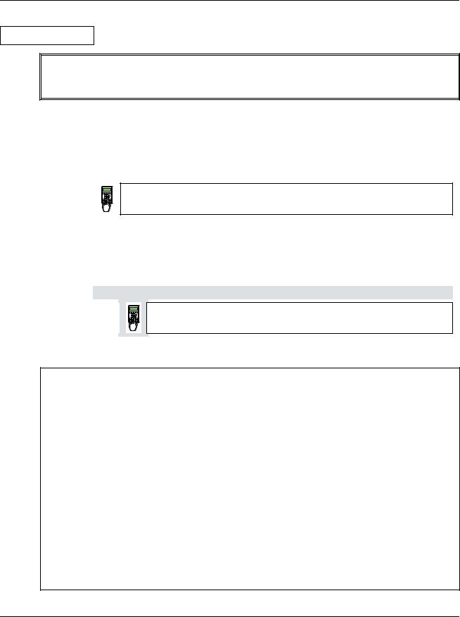
Symbols for switching the electronics or the power section ON and OFF
|
- Switch ON electronics |
X6: 7 „1“ signal |
|
|
- Switch ON power |
(input ON / OFF) |
|
|
|
(K20 in connection example) |
|
|
|
|
|
|
- Switch OFF electronics |
X6: 7 „0“ signal |
|
|
- Switch OFF power |
(input ON / OFF) |
|
|
|
(K20 in connection example) |
|
|
|
|
|
•Binary input DI8; designation RUN
For starting the drive, DI8 must be set to logical „1“. This enables the reference at the REF_SEL and RAMP GENERATOR blocks, as well as the controllers. If DI8 is set to "0“, the drive will react in accordance with the function set at Parameter 916 (shutdown with ramp, with torque limit/current limit, with controller block and coasting).
Once ramp-down has been completed (speed feedback below nmin), the reference is kept at zero, and the controllers blocked after a time-delay; the drive is torqueless.
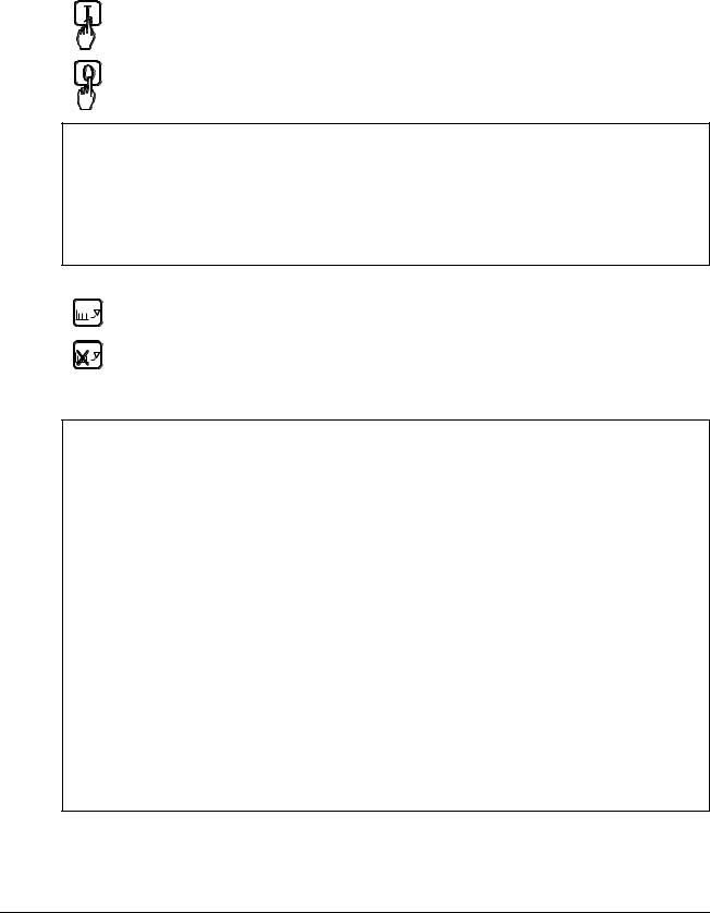
Symbols for enabling / disabling the reference
|
|
|
|
- ENABLE reference |
X6: 8 |
„1“ signal |
(input RUN) |
|
|
|
|||||
|
|
|
|
|
(K21 in connection example) |
|
|
|
|
|
|
|
|
|
|
|
|
|
|
- DISABLE reference |
X6: 8 |
„0“ signal |
(input RUN) |
|
|
|
|
||||
|
|
|
|
|
(K21 in connection example) |
|
|
|
|
|
|
|
|
|
|
System-dependent planning
If you want the drive to react with a function other than that of Parameter 916 or 917, you have to parameterize the unit accordingly, by connecting one of the inputs or an additional one with a control pin, e.g. at the ramp-function generator.
- Example 1:
Operational ramp-up and ramp-down in the event of reference changes with the same ramp times, shutdown via RUN with a different time.
Solution:
use second parameter set ramp times; set time at DECEL2; establish connection from P 1707 to P 10716.
- Example 2:
Implementing an EMERGENCY SHUTDOWN or EMERGENCY STOP function. Solution:
this function stipulated in various regulations must always be planned in dependence on the system involved! A basic distinction must be made here between electrical and mechanical risks. Since one signal at one input is not sufficient (see above), at least one other switch-off option must be created, e.g. by means of a relay directly switch-
ing input DI5 to "0“. This is how the power converter attempts (in accordance with P 917), to defuse the dangerous situation. A dropout-delay contact of the relay will
then switch the power off. If the delay is small or does not match the function selected for P 917, then certain operating states (regeneration) may, due to laws of physics, result in the unit fuses tripping, and in extreme cases in thyristor defects.
DCS 500B / DCP 500B Operating Instructions |
IV A 2 - 3 |
3ADW000055R0401_DCS500B_Operating Instruction_e_d
Chapter 2 - Start-Up Instructions
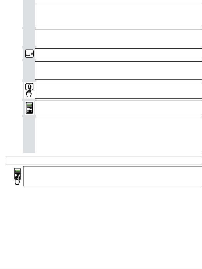
Symbol for altering parameters or for establishing new connections
|
|
|
Enter at keyboard |
e.g. 1204 = 10000 |
Assign the value of 10000 |
|
|
||||
|
|
||||
|
|
|
|
|
to Parameter 1204 |
|
|
|
|
|
|
|
|
|
|
|
|
Symbol for displaying parameter values or connections
Display
Symbol for measuring physical variables
Measure
IV A 2 - 4 |
DCS 500B / DCP 500B Operating Instructions |
3ADW000055R0401_DCS500B_Operating Instruction_e_d

Chapter 2 - Start-Up Instructions
2.1 Preparatory work
Check the unit for damage in transit or other damage.
Install and wire unit; connect all inputs and outputs required.
Proceed in the same way for the field supply unit as well.
Check whether protective measures, earthing, screening, etc. have been taken in accordance with the system conditions involved.
Check the rated value of the supply voltage for the electronics and the fan:
•matching transformer necessary when:
-electronics supply is not equal to 115 V/230 V
-single-phase-fan supply is not equal to 230 V
-three-phase-fan supply is not within the range of 400 V .... 690 V.
Check the rated value of the supply voltage for the armature-circuit converter's power section; the particulars given on the rating plate must be > than the rated line voltage.
If this condition is not satisfied, then the following applies:
-use an isolating transformer, or
-use a suitable unit.
Check the rated value of the supply voltage for the field supply unit. (Particulars on rating plate > rated line voltage?
Is an auxiliary transformer or perhaps a series resistor necessary?)
Check the wiring, fusing, the cross-sectional areas of the cables.
Provide an option for switching binary inputs X6: 7 and X6: 8.
Check the system's EMERGENCY STOP for proper functioning! Set the system-side monitoring functions, and activate them. Check whether auxiliaries, such as motor fans or unit fans, function properly; while doing this, also check for correct direction of rotation and voltage level as well!
DCS 500B / DCP 500B Operating Instructions |
IV A 2 - 5 |
3 A D W 0 0 0 0 5 5 R 0 4 0 1 _ D C S 5 0 0 B _ O p e r a t i n g I n s t r u c t i o n _ e _ d
Chapter 2 - Start-Up Instructions
2.2 Scaling intra-unit signals
Make sure that the existing electronics supply voltage has been set on the SDCS- POW-1 power supply board as well, using the SW1 switch.
If an encoder is being used as the speed feedback device, make sure that the correct supply voltage has been seton the boards
|
|
SDCS-POW-1: X3: / X4: / X5: |
SDCS-IOB-3: S4 |
|
|
|
|
|
|
Switch on the power supply to the electronics section. |
|
|
|
The display of Panel CDP 31x |
DCS 500 |
|
|
may show the following |
** WARNING ** |
|
|
||
|
|
information: |
+Emergency stop |
|
|
|
|
|
|
|
|
522 = GERMAN [Only with the SDCS-CON-2 control board & the CDP 312 panel!]
Activates German texts on the display
501 = Rated motor voltage
This is used to scale those parameters referring to the rated motor voltage, such as field crossover point or maximum speed with e.m.f. control.
502 = Rated motor current
This is used to scale those parameters referring to the rated motor current, such as current limitation or torque limitation.
507 = Rated line voltage
This is used to scale those parameters referring to the line voltage, such as line undervoltage.
Only when connection diagram 1 (Appendix A) is being used!
906 |
= 12502 |
|
„Emergency Stop“ de-activated |
|
|
910 |
= 10908 |
|
No check-back signal from unit fan necessary |
||
911 |
= 10908 |
|
No acknowledge signal from motor fan necessary |
||
Set this only for units with a rated current ≥ 2050A! |
|
|
517 |
= Rated power converter current |
|
Enter numerical value from rating plate here |
||
518 |
= Rated power converter supply voltage |
|
Enter numerical value from rating plate here |
||
519 |
= 45 Grad Celsius |
|
Temperature monitoring of power section |
||
520 |
= 4 Size C4 has been selected |
|
Coding for unit type |
on rating plate: DCS 501 xxxx |
|
521 |
= 1 : Single bridge (2-Q) converter |
|
|
4 : Double bridge (4-Q) converter |
on rating plate: DCS 502 xxxx |
Coding for power section (bridge) type |
|
|
IV A 2 - 6 |
DCS 500B / DCP 500B Operating Instructions |
3ADW000055R0401_DCS500B_Operating Instruction_e_d
|
|
|
|
|
Chapter 2 - Start-Up Instructions |
|
|
|
|
|
|
||
Set this only for units of the DCP 500 series! |
|
|
||||
|
|
|
|
|
|
|
|
|
517 |
= Rated power converter current |
|
|
|
|
|
Enter numerical value from rating plate here |
|
|||
|
|
518 |
= 500 V (fixed!); rated power converter voltage |
|
||
|
|
Enter numerical value 500 V here |
|
|
||
|
|
519 |
= Temperature monitoring of power section |
|
||
|
|
Enter value as indicated in the table „Technical Data“ here |
|
|||
|
|
520 |
= 4 Size C4 has been selected |
|
|
|
|
|
Coding for unit type |
on rating plate: DCP 501 xxxx |
|
||
|
|
521 |
= 1 : Single bridge (2-Q) converter |
|
||
|
|
|
4 : Double bridge (4-Q) converter |
on rating plate: DCP 502 xxxx |
|
|
|
|
Coding for power section (bridge) type |
|
|
||
|
|
507 |
= Rated line voltage; |
|
|
|
|
|
Enter: |
Rated line voltage Uratedline in V * 1.05 |
|
||
|
|
Example: Uratedline = 400 V; entry for Parameter 507 420 |
|
|||
|
|
CAUTION: |
Display of the line voltage feedback value is 5 % too high! |
|
||
|
|
|
|
Switching thresholds referenced to the line voltage, how- |
|
|
|
|
|
|
ever, are correct! |
|
|
CAUTION! Please don't forget!
11202 = SAVE MOT1 SET
Save the altered values in the non-volatile memory!
Resetting the warning either by:
briefly setting ("H“ level) binary input X6:6 or
switching the electronics voltage supply OFF and ON again.
DCS 500B / DCP 500B Operating Instructions |
IV A 2 - 7 |
3ADW000055R0401_DCS500B_Operating Instruction_e_d
Chapter 2 - Start-Up Instructions
2.3 Presetting the field supply unit
Make sure that existing supply voltages for power section, field supply unit (field exciter) and field winding, fan, etc. match the rated data of the components used.
Switch ON power.
 DANGER: System components now energized!
Please wait a few moments. During this time, the unit compares the phase sequence set in the parameter with that obtaining at the power section.
If the unit outputs the "Phase sequence fault of power section“ signalF( 38):
-switch off unit completely and disconnect from the mains, interchange two phases at the input, and start again from the beginning of this chapter.
or
- enter: 506 = R-T-S and then acknowledge fault signal.
Unit will automatically adapt to phase sequence; this signal is to be interpreted as information to the effect that the fans' direction of rotation may be wrong for size-C4 units.
Only for uncontrolled field supply with SDCS-FEX-1!
505 = 1 Panel display: DIODE FIELD EXCIT
Check field current and field voltage by measuring them.
Switch OFF power!
11202 = SAVE MOT1 SET
Save the altered values in the non-volatile memory!
Continue with Chapter 2.4
Only for controlled field supply with SDCS-FEX-2 or DCF 503/DCF 504!
|
|
|
505 |
= 2 |
Panel display: FEX2 OR FEX3 |
|
|
|
|||
|
|
|
|||
|
|
|
503 |
= Rated motor field current |
|
Scales all parameters referenced to the motor field current, such as field current limitation or field current monitoring
1305 = Field current for "Under-excitation" signal
Check field current and field voltage by measuring them; if necessary, correct field current with 503.
|
|
|
|
|
|
IV A 2 - 8 |
|
DCS 500B / DCP 500B Operating Instructions |
3ADW000055R0401_DCS500B_Operating Instruction_e_d
Chapter 2 - Start-Up Instructions
Only for armature-circuit power converters with SDCS-CON-2 control board & CDP 312 panel!
|
1201 = 5 |
Panel display: FEX2/3 AUTOTUNING |
|
Activates the field current controller's auto-tuning function.
Action has been completed when NOT ACTIVATED is shown on the display.
Switch OFF power!
11202 = SAVE MOT1 SET
Save the altered values in the non-volatile memory!
Continue with Chapter 2.4
Only for controlled field supply with DCF 501B or DCF 502B !
505 = 2 Panel display: FEX2 OR FEX3
503 = Rated motor field current
Scales all parameters referenced to the motor field current, such as field current limitation or field current monitoring.
If field current is above 150A, multiply the value by 0.1 and use this number (problem: upper limit of P503 / P504) ; the reference transferred to the DCF 500B is always 100% independent of this setting; by doing so all indications on the panel CDP312 can be corrected quite easily by multiplying by 10
1305 = Field current for "Under-excitation" signal
Switch OFF power!
11202 = SAVE MOT1 SET
Save the altered values in the non-volatile memory!
Before adjustment of the armature-circuit power converter is continued (Chapters 2.4 etc.),
First perform the start-up routine for the DCF 501B or DCF 502B field supply unit (Chapter 2.9) and
then: continue with Chapter 2.4
DCS 500B / DCP 500B Operating Instructions |
IV A 2 - 9 |
3ADW000055R0401_DCS500B_Operating Instruction_e_d

Chapter 2 - Start-Up Instructions
2.4 Adjusting the current controller
Make sure that static current limitation Bridge 1 (2307) and Bridge 2 (2308; with 4Q-unit) have been set to the same value; values of all parameters for current reference limitation must be greater than 20 %; conditions have been satisfied if default setting has been taken as starting point; setting to maximally required motor current is recommended.
Drive must not turn! Do not preset an external reference!
1201 = 3 Panel display: ARM. AUTOTUNING
Activate the current controller's auto-tuning function.
Start the next two steps within the next 20 seconds!
Switch ON power.
 DANGER: System components now energized!
Start drive.
When the display shows NOT ACTIVATED (action correctly completed), stop drive; it may happen that the unit runs armature-circuit current since e.m.f. control is active; nmin - signal (2201) value too small.
Switch OFF power!
If the unit aborts the auto-tuning routine with a fault signal, then eliminate cause of this as far as possible (supply, switching sequence, etc.; see also
description for 11201), then repeat the above points, or continue with next point.
Read out values of: |
|
|
|
|
407 = ............ |
408 = ............ |
409 = ............ |
410 = ............ |
411 = ............ |
Only if the unit aborts the auto-tuning routine with a fault signal FIELD REMOVAL?!
|
505 |
= 0 |
Panel display: NO FIELD EXCITER |
|
|||
|
|||
|
11202 |
= SAVE MOT1 SET |
|
Save the altered values in the non-volatile memory!
Switch OFF power supply to the electronics section! If the SDCS-FEX-1 field supply is being used: make sure that no field current is flowing, e.g. by removing the supply fuses!
Switch the electronics section's power supply on again!
|
|
|
|
|
|
IV A 2 - 10 |
DCS 500B / DCP 500B Operating Instructions |
|
3ADW000055R0401_DCS500B_Operating Instruction_e_d
Chapter 2 - Start-Up Instructions
Drive must not turn! Do not preset an external reference!
1201 = 3 Panel display: ARM. AUTOTUNING
Activate the current controller's auto-tuning function.
Start the next two steps within the next 20 seconds!
Switch ON power.
 DANGER: System components now energized!
Start drive.
When the display shows NOT ACTIVATED (action correctly completed), stop drive; it may happen that the unit runs armature-circuit current since e.m.f. control is active; nmin - signal (2201) value too small.
Switch OFF power!
Read out values of: |
|
|
|
|
407 = ............ |
408 = ............ |
409 = ............ |
410 = ............ |
411 = ............ |
Use values of 409 and 410 from the first auto-tuning routine. Re-activate the field unit used by entering:
a) 505 = 1 Panel display: DIODE FIELD EXCIT and install the supply fuses removed before!
or
b) 505 = 2 |
Panel display: FEX2 OR FEX3 |
CAUTION! Please don't forget!
11202 = SAVE MOT1 SET
Save the altered values in the non-volatile memory!
DCS 500B / DCP 500B Operating Instructions |
IV A 2 - 11 |
3 A D W 0 0 0 0 5 5 R 0 4 0 1 _ D C S 5 0 0 B _ O p e r a t i n g I n s t r u c t i o n _ e _ d
 Loading...