

Page 1

Installation Guide
Digital Zone Processors
640, 640m
641, 641m
1260, 1260m
1261, 1261m
ZonePRO
TM
Page 2
IMPORTANT SAFETY INSTRUCTIONS
WARNING FOR YOUR PROTECTION
READ THE FOLLOWING:
KEEP THESE INSTRUCTIONS
HEED ALL WARNINGS
The symbols shown above are internationally accepted symbols that warn of
potential hazards with electrical products. The lightning flash with arrowpoint
in an equilateral triangle means that there are dangerous voltages present
within the unit. The exclamation point in an equilateral triangle indicates that
it is necessary for the user to refer to the owner’s manual.
These symbols warn that there are no user serviceable parts inside the unit.
Do not open the unit. Do not attempt to service the unit yourself. Refer all
servicing to qualified personnel. Opening the chassis for any reason will
void the manufacturer’s warranty. Do not get the unit wet. If liquid is spilled
on the unit, shut it off immediately and take it to a dealer for service.
Disconnect the unit during storms to prevent damage.
SAFETY INSTRUCTIONS
NOTICE FOR CUSTOMERS IF YOUR UNIT IS EQUIPPED WITH A POWER CORD.
WARNING: THIS APPLIANCE SHALL BE CONNECTED TO A MAINS SOCKET OUTLET WITH A
PROTECTIVE EARTHING CONNECTION.
The cores in the mains lead are coloured in accordance with the following code:
GREEN and YELLOW - Earth BLUE - Neutral BROWN - Live
As colours of the cores in the mains lead of this appliance may not correspond with the
coloured markings identifying the terminals in your plug, proceed as follows:
•
The core which is coloured green and yellow must be connected to the terminal in the plug
marked with the letter E, or with the earth symbol, or coloured green, or green and yellow.
•
The core which is coloured blue must be connected to the terminal marked N or coloured
black.
•
The core which is coloured brown must be connected to the terminal marked L or coloured
red.
This equipment may require the use of a different line cord, attachment plug, or both, depending on the available power source at installation. If the attachment plug needs to be changed,
refer servicing to qualified service personnel who should refer to the table below. The green/
yellow wire shall be connected directly to the units chassis.
FOLLOW ALL INSTRUCTIONS
the apparatus shall not be exposed to dripping or splashing liquid and no object filled with liquid, such as
vases, shall be placed on the apparatus.
CLEAN ONLY WITH A DRY CLOTH.
DO NOT BLOCK ANY OF THE VENTILATION OPENINGS. INSTALL IN ACCORDANCE WITH THE
MANUFACTURER’S INSTRUCTIONS.
DO NOT INSTALL NEAR ANY HEAT SOURCES SUCH AS RADIATORS, HEAT REGISTERS, STOVES, OR OTHER
APPARATUS (INCLUDING AMPLIFIERS) THAT PRODUCE HEAT.
ONLY USE ATTACHMENTS/ACCESSORIES SPECIFIED BY THE MANUFACTURER.
UNPLUG THIS APPARATUS DURING LIGHTNING STORMS OR WHEN UNUSED FOR LONG PERIODS OF TIME.
Do not defeat the safety purpose of the polarized or grounding-type plug. A polarized plug has two blades
with one wider than the other. A grounding type plug has two blades and a third grounding prong. The
wide blade or third prong are provided for your safety. If the provided plug does not fit your outlet, consult
an electrician for replacement of the obsolete outlet.
Protect the power cord from being walked on or pinched particularly at plugs, convenience receptacles, and
the point where they exit from the apparatus.
Use only with the cart stand, tripod bracket, or table specified by the manufacture, or sold with the
apparatus. When a cart is used, use caution when moving the cart/apparatus combination to avoid injury
from tip-over.
CONDUTOR
L LIVE BROWN BLACK
N NEUTRAL BLUE WHITE
E EARTH GND
WIRE COLOR
Normal Alt
GREEN/
YEL
GREEN
WARNING: If the ground is defeated, certain fault conditions in the unit or in the system to
which it is connected can result in full line voltage between chassis and earth ground. Severe
injury or death can then result if the chassis and earth ground are touched simultaneously.
If you want to dispose this product, do n ot mix it with general household waste. There is a
separate collection system for used electronic products in accordance with legislation that
requires proper treatment, recovery and recycling.
Private household in the 25 member states of the EU, in Switzerland and Norway may return their used
electronic products free of charge to designated collection facilities or to a retailer (if you purchase a similar
new one).
For Countries not mentioned above, please contact your local authorities for a correct method of disposal.
By doing so you will ensure that your disposed product undergoes the necessary treatment, recovery and
recycling and thus prevent potential negative effects on the environment and human health.
Refer all servicing to to qualified service personnel. Servicing is required when the apparatus has been
damaged in any way, such as power-supply cord or plug is damaged, liquid has been spilled or objects
have fallen into the apparatus, the apparatus has been exposed to rain or moisture, does not operate
normally, or has been dropped.
POWER ON/OFF SWITCH: The Power switch used in this piece of equipment DOES NOT break the connection from the mains.
MAINS DISCONNECT: The plug shall remain readily operable. For rack-mount or installation where plug is
not accessible, an all-pole mains switch with a contact separation of at least 3 mm in each pole shall be
incorporated into the electrical installation of the rack or building.
If connected to 240V supply, a suitable CSA/UL certified power cord shall be used for this supply.
Page 3

IMPORTANT SAFETY INSTRUCTIONS
DECLARATION OF CONFORMITY
Manufacturer’s Name: dbx Professional Products
Manufacturer’s Address: 8760 S. Sandy Parkway
Sandy, Utah 84070, USA
declares that the product:
Product name: dbx 640, dbx 641
dbx 640m, dbx 641m
Note: Product name may be suffixed by the EU.
Product option: None
conforms to the following Product Specifications:
Safety: IEC 60065 -01+Amd 1
EMC: EN 55022:2006
EN 55024:1998
FCC Part 15
Supplementary Information:
The product herewith complies with the requirements of the:
Low Voltage Directive 2006/95/EC
EMC Directive 2004/108/EC.
RoHS Directive 2002/95/EC
WEEE Directive 2002/96/EC
With regard to Directive 2005/32/EC and EC Regulation 1275/2008 of 17 December
2008, this product is designed, produced, and classified as Professional Audio Equipment and
thus is exempt from this Directive.
Roger Johnsen
Director, Engineering
Signal Processing
8760 S. Sandy Parkway
Sandy, Utah 84070, USA
Date: March 9, 2011
DECLARATION OF CONFORMITY
Manufacturer’s Name: dbx Professional Products
Manufacturer’s Address: 8760 S. Sandy Parkway
Sandy, Utah 84070, USA
declares that the product:
Product name: dbx 1260, dbx 1261
dbx 1260m, dbx 1261m
Note: Product name may be suffixed by the EU.
Product option: None
conforms to the following Product Specifications:
Safety: IEC 60065 -01+Amd 1
EMC: EN 55022:2006
EN 55024:1998
FCC Part 15
Supplementary Information:
The product herewith complies with the requirements of the:
Low Voltage Directive 2006/95/EC
EMC Directive 2004/108/EC.
RoHS Directive 2002/95/EC
WEEE Directive 2002/96/EC
With regard to Directive 2005/32/EC and EC Regulation 1275/2008 of 17 December
2008, this product is designed, produced, and classified as Professional Audio Equipment and
thus is exempt from this Directive.
Roger Johnsen
Director, Engineering
Signal Processing
8760 S. Sandy Parkway
Sandy, Utah 84070, USA
Date: March 9, 2011
European Contact: Your local dbx Sales and Service Office or
Harman Signal Processing
8760 South Sandy Parkway
Sandy, Utah
84070 USA
Ph: (801) 566-8800
Fax: (801) 568-7583
U.K. MAINS PLUG WARNING
A molded mains plug that has been cut off from the cord is
unsafe. Discard the mains plug at a suitable disposal facility.
NEVER UNDER ANY CIRCUMSTANCES SHOULD
YOU INSERT A DAMAGED OR CUT MAINS
PLUG INTO A 13 AMP POWER SOCKET.
Do not use the mains plug without the fuse cover in place.
Replacement fuse covers can be obtained from your local
retailer. Replacement fuses are 13 amps and MUST be
ASTA approved to BS1362.
European Contact: Your local dbx Sales and Service Office or
Harman Signal Processing
8760 South Sandy Parkway
Sandy, Utah
84070 USA
Ph: (801) 566-8800
Fax: (801) 568-7583
ELECTROMAGNETIC COMPATIBILITY
This device complies with part 15 of the FCC Rules and
the Product Specifications noted on the Declaration of
Conformity. Operation is subject to the following two
conditions:
• this device may not cause harmful interference, and
• this device must accept any interference received,
including interference that may cause undesired operation.
Operation of this unit within significant
electromagnetic fields should be avoided.
• use only shielded interconnecting cables.
Page 4

Page 5

ZonePRO
TM
Table of Contents
TOC
Section 1 - Introduction ....................................... 1
1.1 ZonePRO Overview .........................................1
1.2 Features .......................................................1
1.3 Included Items ..............................................2
1.4 ZonePRO Support Resources ............................2
1.5 Service Contact Info .......................................2
1.6 Warranty .......................................................3
Section 2 - ZonePRO Designer GUI .......................... 4
2.1 ZonePRO Designer Overview .............................4
2.2 GUI System Requirements ...............................4
2.3 GUI Installation ............................................5
2.4 Quick Start – Connecting via RS-232 ................5
Section 3 - Getting Started .................................... 8
3.1 Front Panel – 640/640m, 1260/1260m .............8
3.2 Front Panel – 641/641m, 1261/1261m .............9
3.3 Rear Panel ....................................................10
Section 4 - Zone Controllers .................................. 12
4.1 ZC Descriptions ..............................................12
4.2 ZC Wiring ......................................................15
4.3 ZC-4 Wiring ...................................................18
4.4 ZC DIP Switches & Programming ......................19
Section 5 - Link I/O .............................................. 22
5.1 Link I/O Overview ..........................................22
5.2 Jumpers .......................................................22
5.3 Link I/O Wiring .............................................24
Section 6 - Networking ......................................... 25
6.1 Default ZonePRO Network Settings ...................25
6.2 Networking Overview ......................................25
6.3 Overview of TCP/IP Basics ..............................26
6.4 Connecting via direct-connect Ethernet ............27
6.5 Setup of a simple isolated Ethernet network ......28
6.6 Adding the ZonePRO to an existing Local Area
Network .............................................................30
6.7 Proxy ...........................................................31
6.8 Virtual Private Networks (VPN) ........................32
6.9 Network Considerations and Limitations ............32
6.10 Network Troubleshooting ...............................33
Section 7 - Application Guide ................................ 34
7.1 Restaurant Application ...................................34
7.2 Health Club Application ..................................36
7.3 Nightclub Application .....................................38
Section 8 - Appendix ............................................ 40
8.1 ZonePRO 640/641 Block Diagram .....................40
8.2 ZonePRO 640m/641m Block Diagram ................41
8.3 ZonePRO 1260/1261 Block Diagram ..................42
8.4 ZonePRO 1260m/1261m Block Diagram .............43
8.5 Firmware Updates ..........................................44
8.6 Factory Reset Procedures ................................44
8.7 Technical Specifications ..................................46
8.8 Wiring Diagrams ............................................51
8.9 Copyrights ....................................................52
Page 6

Page 7
ZonePRO
Introduction
Section 1 - Introduction
1.1 ZonePRO Overview
Congratulations on your purchase of the dbx® ZonePRO. The ZonePRO products are based
on the same unparalleled design philosophy that made the DriveRack family famous. This
philosophy, “To provide everything you need between the sources and the amplifiers”, creates
a full-featured processor capable of almost any BGM or commercial audio application.
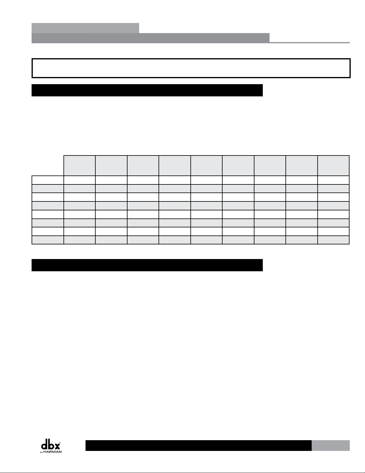
The proceeding chart outlines the major differences between the dbx ZonePRO models.
TM
Section 1
Balanced
Total Inputs Total Outputs
1260m 12 6 6 4 Pair
1260 12 6 2 8 Pair
1261m 12 6 6 4 Pair
1261 12 6 2 8 Pair
640m 6 4 4 2 Pair
640 6 4 2 4 Pair
641m 6 4 4 2 Pair
641 6 4 2 4 Pair
Mic/Line
Inputs
1.2 Features
• AdvancedFeedbackSuppression(AFS™)
• AutoWarmth®
• AutoGainControl(AGC)
• AmbientNoiseCompensation(640m,641m,1260m,&1261m
modelsonly)
• Bandpass/CrossoverFilters
• Compression
• Delay
• De-Essing
• Limiting
• NoiseGating
• NotchFiltering
• ParametricEQ
Unbalanced
RCA Line
Inputs
2 Channel
S/PDIF Input
Q Q Q Q Q
Q Q Q Q
Q Q Q Q
Q Q Q
• 2LevelPriorityDucker
• Configuration,Scene,&ScheduleWizards
• CompatiblewithdbxZCWallPanelControllers
• IndependentRoutingofSourcestoZones
• IndependentMixingofSourcestoZones(640&641donot
• IndependentZoneVolume&SourceSelectionControl
• RS-232&EthernetControl(640&641modelsdonotsupport
• SecurityLockout
• SwitchableMic/LineInputs
• IEC,UI,andCSACertified
Front Panel
Control
Q Q Q Q
Q
supportsourcemixing)
Ethernetcontrol)
Ethernet
Port
Q Q Q
Mix Sources
to Zones
Ambient Noise
Compensation
1
Page 8

Section 1
Introduction
1.3 Included Items
• ZonePRO Processor
• Power Cable
• RS-232 Null Modem Cable
• Ethernet Crossover Cable (excluded from 640 & 641 models)
• Software CD-ROM
• Installation Guide
1.4 ZonePRO Support Resources
ZonePRO Designer Help - After installing the ZonePRO Designer GUI, see the included help for
detailed information regarding ZonePRO programming and configuration.
Training Videos - Training videos can be found under the “Training” section of our website
located at www.dbxpro.com.
FAQs/Solutions - Answers to frequently asked questions and solutions to common problems
can be found under the “Support” section at www.dbxpro.com.
dbx User Forum - The dbx User Forum can be found at www.dbxpro.com. Here you can search
the forum for specific topics or ask other ZonePRO users questions regarding the ZonePRO
products.
ZonePRO
TM
1.5 Service Contact Info
If you require technical support, contact dbx Technical Support. Be prepared to accurately
describe the problem. Know the serial number of your device – this is printed on a sticker
attached to the chassis. If you have not already taken the time to register your product,
please do so now. You may register online at www.dbxpro.com or fill out and send in the
included warranty registration card.
Before you return a product to the factory for service, we recommend you refer to the manual.
Make sure you have correctly followed installation steps and operation procedures. For further
technical assistance or service, please contact our Technical Support Department at (801)
568-7660 or visit the support pages at www.dbxpro.com. If you need to return a product
to the factory for service, you MUST first contact Technical Support or fill out the return
authorization request form on the website to obtain a Return Authorization Number.
No returned products will be accepted at the factory without a Return Authorization
Number.
Please refer to the Warranty information on the following page, which extends to the first
end-user. After expiration of the warranty, a reasonable charge will be made for parts, labor,
and packing if you choose to use the factory service facility. In all cases, you are responsible
for transportation charges to the factory. dbx will pay return shipping if the device is still
under warranty.
Use the original packing material if it is available. Mark the package with the name of the
shipper and with these words in red: DELICATE INSTRUMENT, FRAGILE! Insure the package
properly. Ship prepaid, not collect. Do not ship parcel post.
2
Page 9

ZonePRO
1.6 Warranty
This warranty is valid only for the original purchaser and only in the United States.
1. The warranty registration card that accompanies this product must be mailed within 30
days after purchase date to validate this warranty. You can also register online at www.
dbxpro.com. Proof-of-purchase is considered to be the responsibility of the consumer. A
copy of the original purchase receipt must be provided for any warranty service.
2. dbx warrants this product, when bought and used solely within the U.S., to be free from
defects in materials and workmanship under normal use and service.
3. dbx liability under this warranty is limited to repairing or, at our discretion, replacing
defective materials that show evidence of defect, provided the product is returned to dbx
WITH RETURN AUTHORIZATION from the factory, where all parts and labor will be covered
up to a period of two years. A Return Authorization number must first be obtained from
dbx. The company shall not be liable for any consequential damage as a result of the
product’s use in any circuit or assembly.
4. dbx reserves the right to make changes in design or make additions to or improvements
upon this product without incurring any obligation to install the same additions or
improvements on products previously manufactured.
Introduction
TM
Section 1
5. The foregoing is in lieu of all other warranties, expressed or implied, and dbx neither
assumes nor authorizes any person to assume on its behalf any obligation or liability in
connection with the sale of this product. In no event shall dbx or its dealers be liable for
special or consequential damages or from any delay in the performance of this warranty
due to causes beyond their control.
3
Page 10
Section 2
ZonePRO Designer GUI
Section 2 - ZonePRO Designer GUI
2.1 ZonePRO Designer Overview
ZonePRO
TM
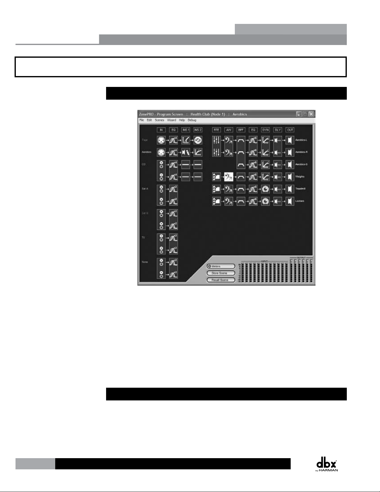
The ZonePRO Designer Graphic User Interface (GUI) is the included software application which
is used for programming the ZonePRO products. The GUI provides network tools for configuring
your control network as well as multiple “Wizard” functions for configuring the system routing
and in-wall dbx Zone Controllers. The GUI also allows you to adjust DSP effect parameters and
even create automatic system changes (referred to as “Scene Changes”).
Understanding the ZonePRO Designer GUI is essential for getting the most out of the ZonePRO
processors. After installing the ZonePRO Designer GUI, please see the software application’s
help section for detailed information and assistance with the ZonePRO Designer GUI. Training
videos are also available at www.dbxpro.com.
2.2 GUI System Requirements
1 GHz or faster processor
Windows 2000/XP/Vista (32 bit)/7 (32 bit)
256 MB RAM (512 MB Recommended)
Recommended screen resolution: 1024 x 768 pixels or higher
4
Page 11
ZonePRO
Computer
ZonePRO
2.3 GUI Installation
1. Install the ZonePRO GUI software onto your computer from either the dbx website at
www.dbxpro.com or from the included CD ROM.
We highly recommend disabling virus protection software during the installation
of ZonePRO Designer.
2. The application will proceed to prompt you for the installation location.
3. Once the software installation has been completed, it is recommended that you restart
your computer.
2.4 Quick Start – Connecting via RS-232
In order to program the ZonePRO processors, the ZonePRO Designer GUI must be in
communication with the ZonePRO device (this is referred to as “Online”). Once communication
is established, the ZonePRO processor can be programmed in real-time, or if a program has
already been created, it can be loaded into the device.
ZonePRO Designer GUI
TM
Section 2
If your computer does not have a built in RS-232 port you must use a compatible RS-232
peripheral, such as an RS-232 PCI card, RS-232 PCMCIA card, or USB to Serial adapter. Please
visit the FAQs section of the dbx website for the latest information on compatible RS-232
peripherals.
Most ZonePRO models also allow you to communicate via Ethernet, the exception being the
640 and 641 models, which do not have an Ethernet control port. If you are connecting via
Ethernet and require assistance, please see “Section 6 - Networking”.
It is highly recommended that ZonePRO installers do have the means to communicate
with the ZonePRO processors via RS-232. If a firmware update is ever required, the firmware
update must be applied using the RS-232 connection!
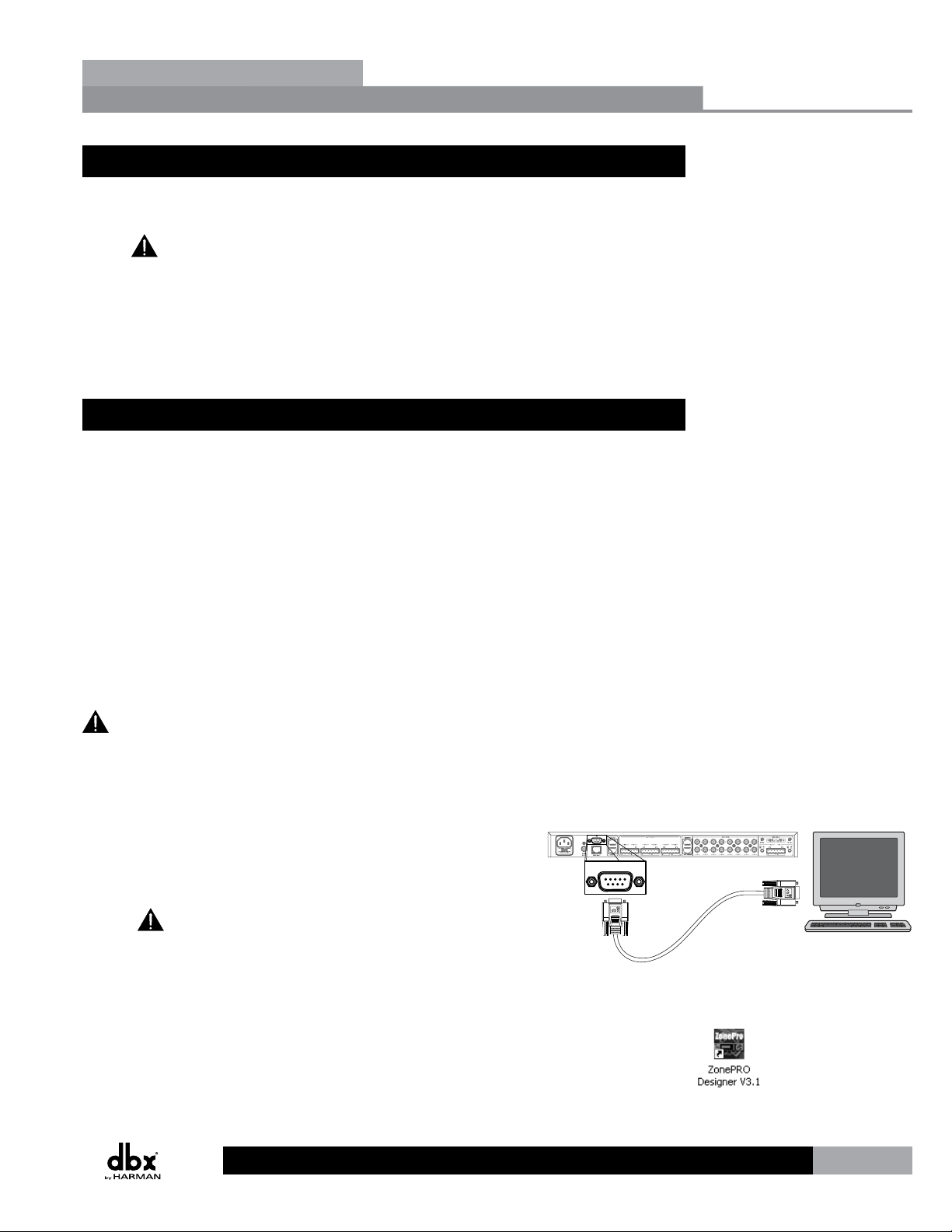
Going Online via RS-232
1. Connect your computer to the ZonePRO’s front or rear RS-232
port using the provided dbx female to female null modem
cable.
A straight-through RS-232 cable will not work! If using
a USB to Serial adapter, the dbx null modem cable must be
plugged in between the adapter and the ZonePRO. See section
“8.8 Wiring Diagrams” for a wiring diagram of the RS-232 null
modem cable.
PC
dbx RS-232 Cable
2. Launch ZonePRO Designer.
5
Page 12
Section 2
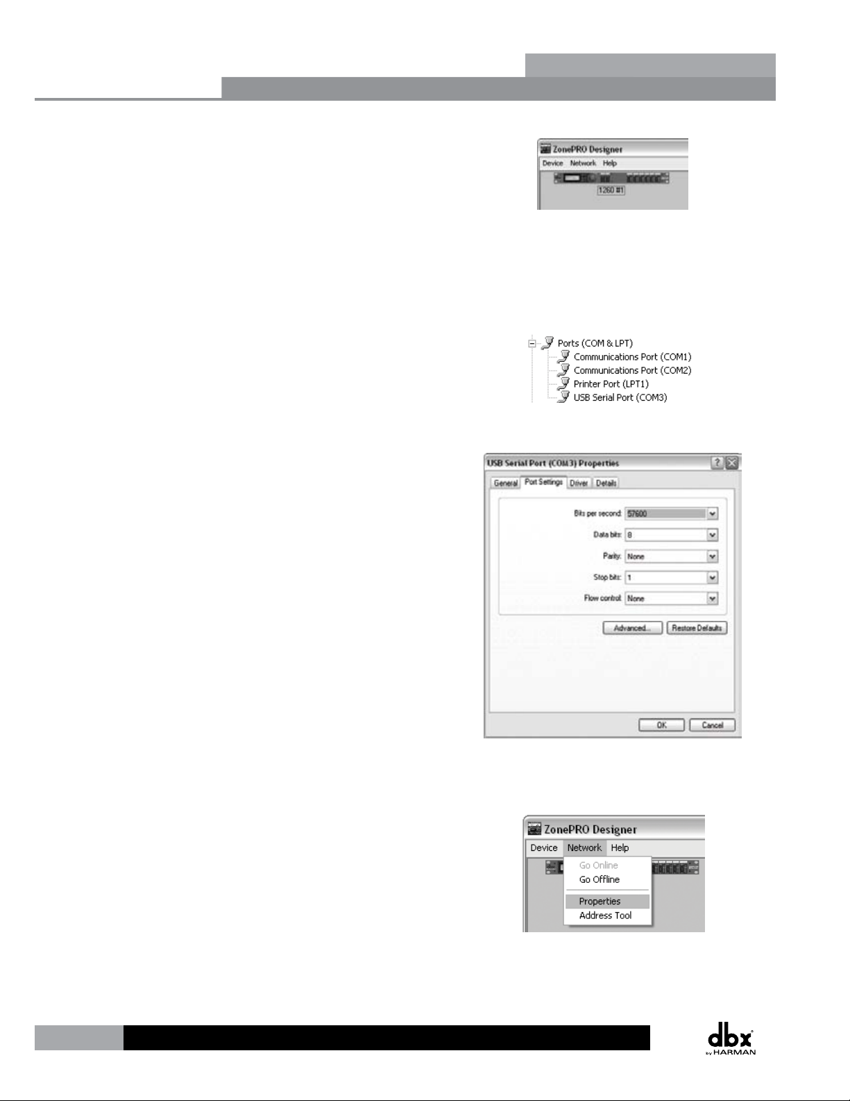
3. Wait approximately 10 seconds after the main ZonePRO
Designer window has appeared. If a ZonePRO icon appears in
the upper left hand corner of the window, you are online with
the processor and ready to begin programming. Simply double
left click on the ZonePRO icon to open the Program Screen and
begin programming. If the icon does not automatically appear,
proceed with these instructions.
4. Go into Window’s Device Manager > Ports. Take note of your
COM port’s assigned COM number (shown in parenthesis). If
you do not see your COM port here, you may need to reinstall
the drivers for your COM port peripheral.
5. Double left click on the connected COM port listed in the
previous step. Click the Port Settings tab and set your COM
port settings as shown to the right then click the OK button.
ZonePRO Designer GUI
ZonePRO
TM
6. Go back into ZonePRO Designer and go to Network >
Properties.
6
Page 13
ZonePRO
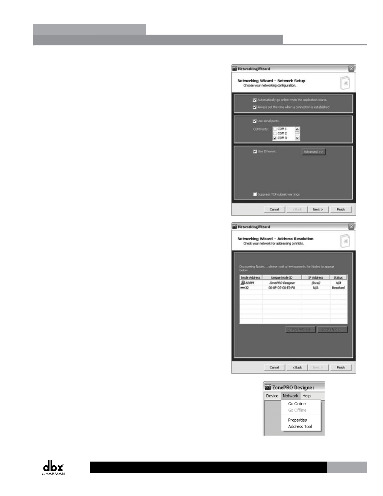
7. Ensure that the “Automatically go online when the application
starts” option is checked and the “Use serial ports” option is
checked. In the COM Ports combo box, uncheck any unused
COM ports and check only the COM port number which you
noted in step 4. Click the Next button twice.
ZonePRO Designer GUI
TM
Section 2
8. Your connected ZonePRO device should appear on the second
row of the table and have a Status of “Resolved”. If it does
not, ensure that the RS-232 cable is securely connected and
that you are using the correct RS-232 cable and a compatible
RS-232 peripheral. If the ZonePRO device appears in the table
proceed by clicking the Finish button.
9. Select Network > Go Online. The icon of the ZonePRO
should now appear in the upper left corner of the window.
You are now online with the processor and ready to begin
programming. Simply double left click on the ZonePRO icon to
open the Program Screen and begin programming.
7
Page 14
2657657657657
341
2657657657657
3
4
1
265
765
765
765
765
765
7
3
4
1
657657657657657657234
1
Section 3
Section 3 - Getting Started
Getting Started
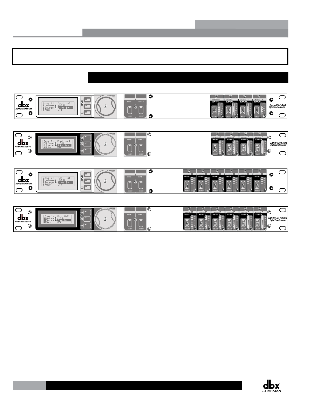
3.1 Front Panel – 640/640m, 1260/1260m
640 Front Panel
640m Front Panel
1260 Front Panel
ZonePRO
TM
SELECTSELECT
1260m Front Panel
SELECTSELECT SELECTSELECTSELECT SELECTSELECTSELECT
1. Front Panel LCD
Displays information relating to parameters such as source selection, page steering,
zone volumes, and mutes.
2. Parameter Select Buttons 1-3
Allows selection of parameters on display.
3. Data Wheel
Used to edit parameter values.
4. Page Buttons
Allows paging microphone path selection for page steering of the ML1 and ML2 inputs.
5. Output Select Button
Allows selection of outputs for controlling source selection, zone volume control, and
zone muting.
SELECTSELECTSELECT SELECTSELECTSELECT
1260
Z
one
PRO
Digital Zone ProcessorDigital Zone Processor
6. Output Meter
Six-segment output level meter representing -30dBu to +20dBu.
7. Threshold Indicator
Indicates that the threshold level has been exceeded within the output dynamics
processor and that dynamics processing may be occurring.
8
Page 15
ZonePRO
1
3
123
123
123
TM
and dynamics processing may be occurring.
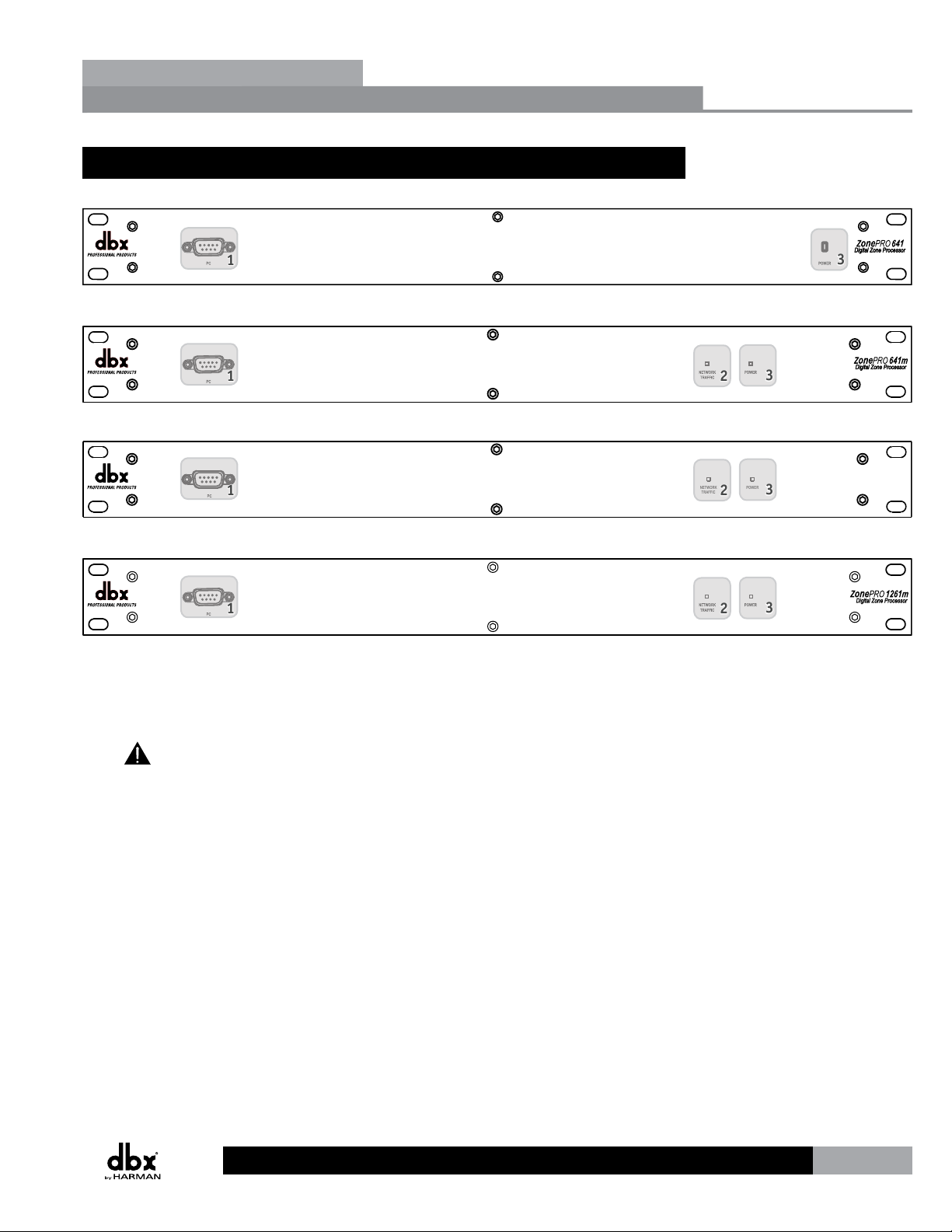
3.2 Front Panel – 641/641m, 1261/1261m
641 Front Panel
641m Front Panel
1261 Front Panel
Gettibg Started
NETWORK
TRAFFIC
Section 3
ZonePRO1261
POWER
Digital Zone Processor
1261m Front Panel
1. Front PC Port (RS-232)
Connect this serial port to the PC for configuration, control, and monitoring. It can
also be used for communication with a third party control system. The baud rate of this
port is 57600.
Front and rear PC ports should not be used at the same time!
2. Network Traffic LED (641m, 1261, and 1261m only)
This LED (when lit), indicates that network traffic is present.
3. Power LED
This LED (when lit) indicates that the ZonePRO device is currently powered on.
9
Page 16
768
11
11
10
10
12
1
3
5
9
9
768
1111111010
12
12
134
5
999
7
6
8
11
11
10
12
1
234
5
9
9
8
7
6
123
4
5
111111
101010
12
12
12
999
11
9
Section 3
S/PDIF
INPUT
RS-232
ETHERNET
10/100 BaseT
Getting Started
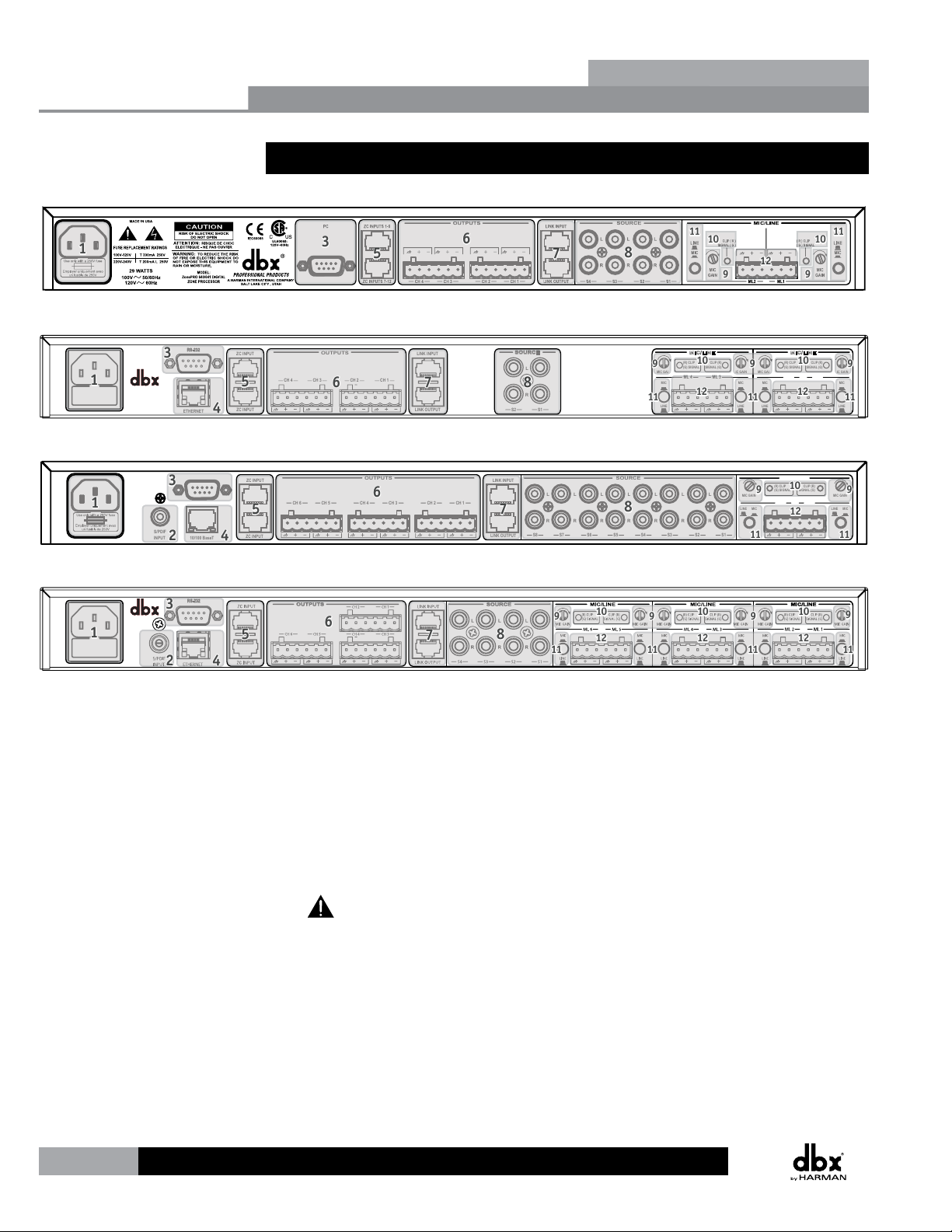
3.3 Rear Panel
640/641 Rear Panel
640m/641m Rear Panel
OUTPUTS
CH 3CH 4 CH 1CH 2
ZC INPUT
LINK INPUTZC INPUT
LINK OUTPUT
1260/1261 Rear Panel
PC
ZC INPUT
CH 6 CH 5 CH 3 CH 2 CH 1 ML 2 ML 1CH 4
ZC INPUT
OUTPUTS
SOURCE
L
R
S2 S1
LINK INPUT
S8 S7 S6 S4 S2S5 S3 S1
LINK OUTPUT
ZonePRO
MIC/LINE
(R) CLIP
CLIP (R)
(G) SIGNAL
MIC
LINE
SIGNAL (G)
ML 4 ML 3
MIC GAIN MIC GAIN
SOURCE MIC/LINE
LL L LL L L
RR R RR R R
MIC GAIN MIC GAIN
MIC
LINE
MIC GAIN MIC GAIN
LINE
MIC
MIC
LINE
(R) CLIP
(G) SIGNAL
ML 2 ML 1
(R) CLIP
(G) SIGNAL
MIC/LINE
SIGNAL (G)
CLIP (R)
SIGNAL (G)
CLIP (R)
MIC
LINE
LINE
MIC
TM
RS-232
1260m/1261m Rear Panel
1. Power Connector
Connect the included AC power cable to this IEC connector.
2. S/PDIF Input (1260, 1261, 1260m, and 1261m models only)
Digital audio input for up to two channels of digital audio.
3. Rear PC Port (RS-232)
Connect this serial port to the PC for configuration, control, and monitoring. It can
also be used for communication with a third party control system. The baud rate of this
port is 57600.
Front and rear PC ports should not be used at the same time!
4. Ethernet Port (all models except 640 and 641)
Connect this Ethernet port to the PC for configuration, control, and monitoring. It can
also be used for communication with a third party control system.
10
Page 17
ZonePRO
Stereo RCA
Connection Example
5. ZC Input Ports
Allows connection of up to 12 ZC controllers (six per port) for control of volume, source
selection, page steering, and scene changes. The top ZC Input port is for IDs 1-6 and
the bottom ZC Input port is for IDs 7-12.
6. Analog Outputs
Balanced audio output connections. Connect these outputs to your amplifier input
channels.
7. Link Input/Output Ports
Allows duplication of up to six input channels (ML1, ML2, S1, S2, S3, S4) to another
ZonePRO device in applications where additional output zones are required.
All models – with the exception of the 640m and 641m – allow duplication of
up to six channels: ML1, ML2, S1, S2, S3, S4. The 640m and 641m models allow
duplication of up to four channels: ML1, ML2, S1, S2.
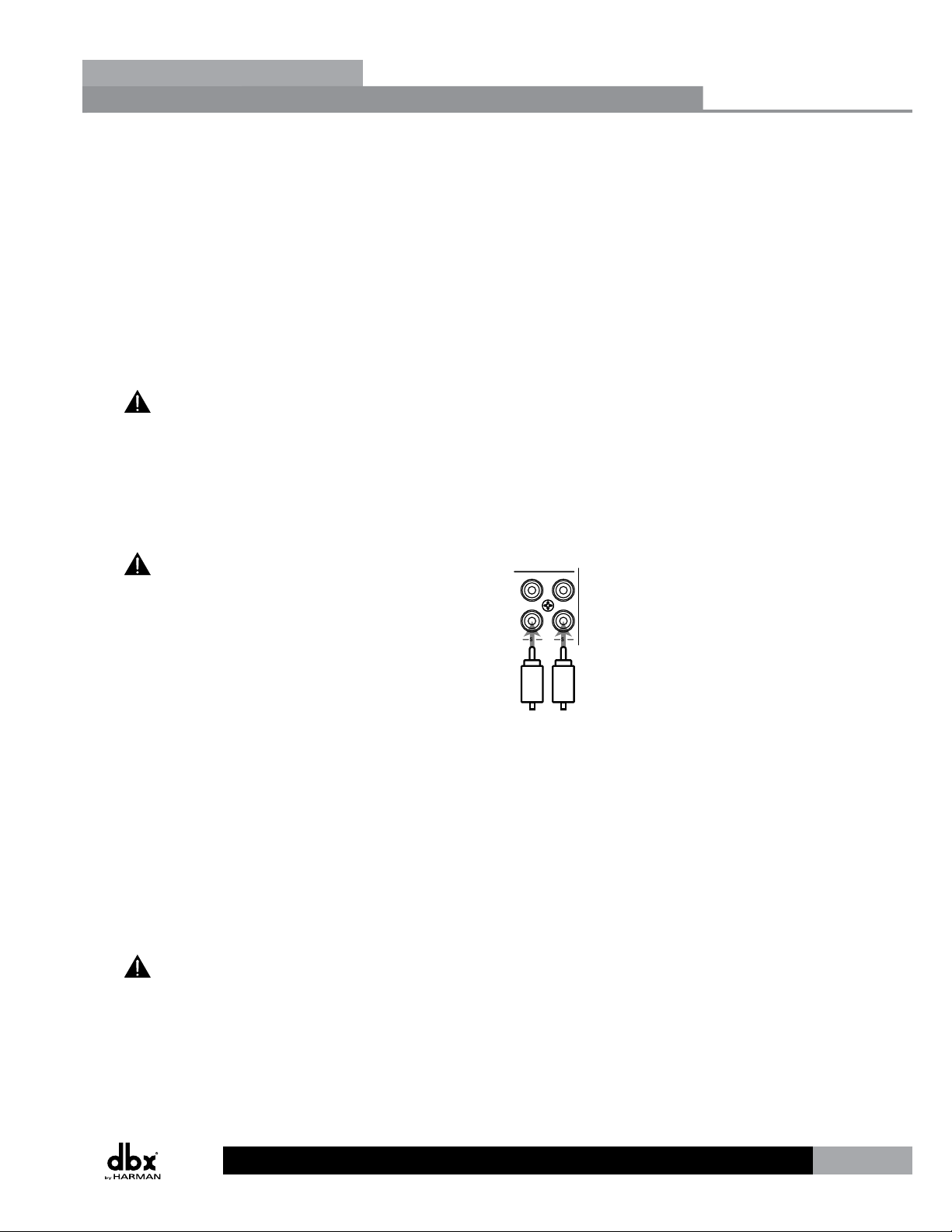
8. RCA Source Inputs
Mono-summed pairs of unbalanced RCA audio inputs.
Gettibg Started
TM
Section 3
Each pair of unbalanced RCA inputs are
internally mono summed. This is beneficial when
your application requires mono zones. However, when
stereo zones are required and stereo imaging is to be
maintained, each stereo source must occupy two pairs
of inputs (omitting one jack per pair).
LL
RR
S2 S1
9. Mic Gain Control
Allows microphone gain control when the mic/line inputs are set to mic level.
10. Signal/Clip LED
This LED indicates when signal is present (green) or the input is clipping (red).
11. Mic/Line Switch
Allows configuration for microphone or line level sources.
12. Mic/Line Input Connectors
These balanced inputs provide Euroblock connectors for mic or line level sources.
These Euroblock inputs provide 15 Volts of phantom power when the mic/line
switch is set to mic level.
LeftRight
11
Page 18
Section 4
Zone Controllers
Section 4 - Zone Controllers
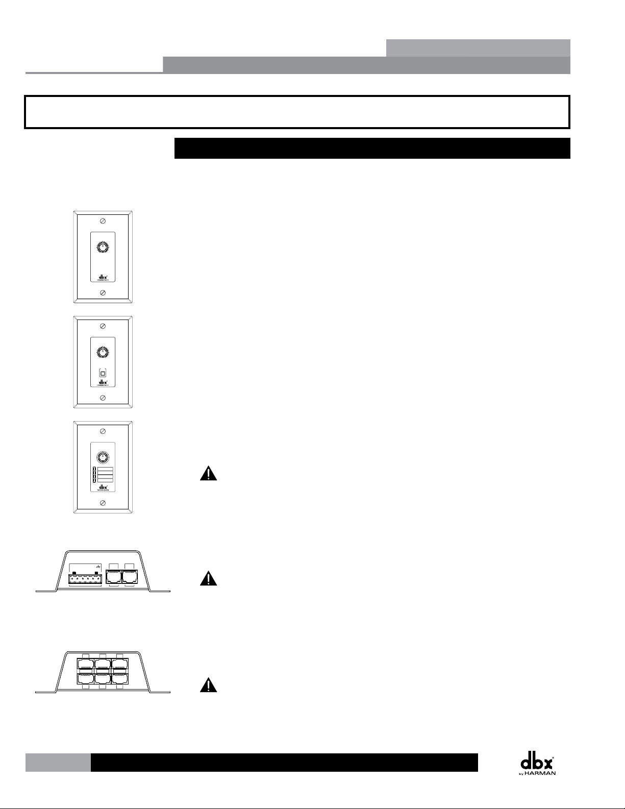
4.1 ZC Descriptions
The dbx Zone Controllers (ZCs) provide a user friendly solution for controlling different
functions of the ZonePRO processors. The following section provides a description of each of
these ZC models.
VOLUME
456
3
7
2
8
1
9
0
10
VOLUME
456
3
7
2
8
1
9
0
10
MUTE
ZC-1 – The ZC-1 is a programmable zone controller that allows input or output volume
level control from a wall panel.
ZC-2 – The ZC-2 is a programmable zone controller that allows output volume level and
mute control from a wall panel.
ZonePRO
TM
SELECT
A
B
A
B
C
D
1+V2 3 4 INOUT
1 2 3
4 5 6
C
D
ZC-3 – The ZC-3 is a programmable zone controller that allows control of source selection,
page steering, or scene selection via a four position rotary control.
The ZC-3 must be assigned as ID#1 and connected to the ZonePRO’s top ZC Input
connector for scene selection control.
ZC-4 – The ZC-4 is a programmable zone controller that allows control of source selection,
page steering, or scene selection via contact closure.
The ZC-4 must be assigned as ID#1 and connected to the ZonePRO’s top ZC Input
connector for scene selection control.
ZC-BOB – The ZC-BOB allows parallel (also known as “home run”) cabling of the Zone
Controllers.
Each ZonePRO device can accommodate up to two ZC-BOBs. Daisy chaining ZCs off
the ZC-BOB is not supported!
12
Page 19

ZonePRO
TM
Zone Controllers
Section 4
VOLUME
ZC-6
A
B
C
D
ZC-7
VOLUME
SELECT
A
B
A
C
B
D
C
D
ZC-8
D E
C
F
B
G
A
H
A
B
C
D
E
F
G
H
ZC-9
ZC-6 – The ZC-6 is a push-button up/down input or output volume controller.
ZC-7 – The ZC-7 is a programmable zone controller that allows control of page steering via
four momentary push buttons. The ZC-7 has 5 states: button A pressed, button B pressed,
button C pressed, button D pressed, and “no button pressed” being the 5th state.
ZC-8 – The ZC-8 is used for combination up/down output volume control and four position
source selection control.
ZC-9 – The ZC-9 provides source selection control via an eight position rotary selector.
CLOSURE
RJ45 - CONNECT ONLY TO
CONTROL
VOLTAGE
5-24 VDC
ZONE CONTROLLER INPUT
OUT
IN
INPUTS
RELAY/
SWITCH
ZC-FIRE – The ZC-FIRE is the interface to generic fire alarm relays. When the fire alarm
activates, the general purpose relay can typically be programmed to close if normally
open or vices-versa. The ZC-FIRE interface unit monitors the state of the relay (n.o. or
n.c.) and upon the state of change, notifies the ZonePRO to mute the outputs or load a
pre-programmed “Fire” scene. Control Voltage (5-24 VDC) can also be used for triggering the
ZC-FIRE.
The ZC-FIRE must be assigned as ID#2 and connected to the ZonePRO’s top ZC
Input connector for fire control.
13
Page 20

Section 4
Zone Controllers
The below matrix table shows a side-by-side comparison of the ZC’s features.
ZonePRO
TM
14
Page 21

ZonePRO
Zone Controller Cable Specications:
4.2 ZC Wiring
The installation of the Zone Controllers MUST be accomplished with the use of cable which is
rated VW-1 or higher. Common NEC designations which meet this rating include: CMP, CMR,
CMG, CM and CMX.
The below diagram shows the internal color coding of a compatible straight-through, 568B
standard Cat 5 cable. It also illustrates which DIP switch settings and controller ID numbers
correspond with each wire inside the Cat 5 cable.
Cat 5 Cable / 4-Twisted Pairs of 24 AWG Wire / 568B Standard
Zone Controllers
TM
Section 4
RJ-45
(8-Position)
1 1
2 2
3 3
4 4
5 5
6 6
7 7
8 8
White / Orange
Orange
White / Green
Blue
White / Blue
Green
White / Brown
Brown
RJ-45
(8-Position)
Voltage Reference
Controller 1/7
Controller 2/8
Controller 3/9
Controller 4/10
Controller 5/11
Controller 6/12
Ground
ON
1 2 3 4 5 6
ON
1 2 3 4 5 6
ON
1 2 3 4 5 6
ON
1 2 3 4 5 6
ON
1 2 3 4 5 6
ON
1 2 3 4 5 6
The included Ethernet crossover cable cannot be used to connect ZCs to the ZonePRO!
All Zone Controllers can be wired serially or in parallel. Whether using serial or parallel
cabling, each Zone Controller must have a unique identification number chosen using the DIP
switches on the side of the controller (see Diagram A), although there may be multiple Zone
Controllers controlling a single zone or a single Zone Controller that controls multiple zones.
This is explained in further detail in “Section 4.4 ZC DIP Switches & Programming”.
Diagram A
Two Zone Controllers cannot be used to control the same parameter within the ZonePRO
device!
15
Page 22

Diagram A
Diagram A
RJ45
CONNECT ONLY TO
ZONE CO NTROLLE
R
INPUT
.
IEC60065
UL-6500
80-1342-A
RJ45
CONNECT ONLY TO
ZONE CO NTROLLE
R
INPU
T
.
IEC60065
UL-6500
80-1342-A
ID# 1 ID# 4
Diagram B
RS-232
Section 4
Zone Controllers
Wiring In Series
To wire the Zone Controllers in series, daisy chain each ZC using the ports on each (see
Diagram B) then connect one of the ZCs to the appropriate ZC Input Port on the ZonePRO
device. It is not important which ZC port you use on each ZC or which ZC in the chain is
connected to the ZonePRO device.
Diagram B
ID# 1 ID# 4
ZonePRO
TM
80-1342-A
.
R
RJ45
INPUT
CONNECT ONLY TO
ZONE CO NTROLLE
80-1342-A
UL-6500
IEC60065
UL-6500
IEC60065
.
R
RJ45
T
INPU
CONNECT ONLY TO
ZONE CO NTROLLE
RS-232
Wiring In Parallel
To wire the Zone Controllers in parallel, a ZC-BOB must be used. To wire in parallel, each
Zone Controller must be wired into one of the ZC-BOB’s numbered ports. The ZC BOB’s
Output port is then connected to one of the ZonePRO’s ZC Input ports (see Diagram C). For
troubleshooting purposes, it is recommended to match the numbered ports on the ZC-BOB
with the corresponding DIP switch assignments on each ZC (for example, ID#6 or ID#12 would
be connected to the #6 port on the ZC-BOB).
Diagram C
RS-232
16
Each ZonePRO device can accommodate up to two ZC-BOBs. Daisy chaining ZCs off the
ZC-BOB is not supported!
Page 23

ZonePRO
RJ-45
(8-Position)
RJ-45
(8-Position)
Orange
White/Blue
Green
Blue
White/Brown
Brown
-VREF
-Dip 1
-GND
1
2
3
4
5
6
7
8
1
2
3
4
5
6
7
8
White/Green
White/Orange
Cable Specification: EIA/TIA 568A Standard (pin to pin) 24 AWG wire
-Dip 2
-Dip 3
-Dip 4
-Dip 5
-Dip 6
Maximum Cable Lengths
Depending upon how many controllers you are connecting to the ZonePRO and whether you
are wiring the ZCs in parallel or serially, there are certain cable length restrictions.
Diagram A shows the maximum cable length for 3 ZCs wired in serial. Diagram B shows the
maximum cable length for 6 ZCs wired in serial. Diagram C shows the maximum length for
each cable run when connecting the ZCs in parallel using a ZC-BOB and the maximum cable
length of the cable between the ZC-BOB and ZonePRO device.
Diagram A
RS-232
Diagram B
Zone Controllers
RS-232
TM
Section 4
Diagram C
RS-232
Number of ZCs Daisy Chained in Series Maximum Total Cable Length
1 ZC 1000 ft.
2 ZCs 800 ft.
3 ZCs 600 ft.
4 ZCs 500 ft.
5 ZCs 400 ft.
6 ZCs 300 ft.
17
Page 24

Section 4
Zone Controllers
4.3 ZC-4 Wiring
The below diagrams show how to configure and wire a ZC-4 for contact closure control using
relays or SPDT (single pole double throw) type switches.
All pins on the ZC-4 must be connected! Any pins not directly connected to a switch or
relay should be connected to the +V pin.
ZonePRO devices.
ZonePRO
controller.
TM
18
Page 25

ZonePRO
4.4 ZC DIP Switches & Programming
When configuring the ZCs, there are two steps which need to be completed before the ZCs will
function:
• Step 1: Assign the ZC IDs and perform the ZC Configuration programming
• Step 2: Associate the ZCs
The programming of the ZCs is performed using the
Configuration Wizard in ZonePRO Designer.
Step 1: Assign the ZC IDs and perform the ZC Configuration programming
The ID# assignments on each Zone Controller, set using the DIP switches on the side of each,
must correspond with the appropriate ZC Input port on the back of the ZonePRO device and
with the program loaded into the ZonePRO.
Zone Controllers
TM
Section 4
Top ZC Input Port (1-6)
The top ZC Input port on the back of the ZonePRO
device corresponds with ID#s 1-6. Therefore, to
select ID#2 for example, simply flip the 2 DIP
switch into the on position and connect the ZC to
the top ZC Input port on the ZonePRO. You must
then program this ZC, on the corresponding ZC
Panel Configuration page in ZonePRO Designer’s
Configuration Wizard, as ZC Input 2 (ID#2).
Bottom ZC Input Port (7-12)
The bottom ZC Input port on the back of the
ZonePRO device corresponds with ID#s 7-12. The
physical DIP switch settings simply start over or
repeat when connecting to the bottom ZC Input
port on the ZonePRO. For example, to create ID#s
7-12, add 6 to the ID# selected on the ZC’s DIP
switch. For example, to get an ID# of 10, connect
to the bottom ZC Input port and set the ID# to
4 (4+6=10). You must then program this ZC, on
the corresponding ZC Panel Configuration page in
ZonePRO Designer’s Configuration Wizard, as ZC
Input 10 (ID#10).
ZonePRO Designer
Software Programming
ZC INPUT
ZC INPUT
ID’s 7-12
(Bottom ZC Input Port)
ZC-3
A
B
C
D
ID#2
SwitchesZCs
SELECT
A
B
C
D
DIP
Switches ZCs
ZC-3
A
B
C
D
DIP
ID#10
ID’s 1-6
(Top ZC Input Port)
SELECT
A
B
C
D
ZonePRO Designer
Software Programming
ZC INPUT
ZC INPUT
19
Page 26

ID’s 1-6
ID’s 7-12
Section 4
Zone Controllers
The below diagram shows an example of the DIP switch ID assignments, ZC Input port
connections, and ZC Panel Configuration programming for 12 Zone Controllers.
ZonePRO
TM
(Top ZC Input Port)
ZonePRO Designer
Software Programming
DIP
Switches ZCs
ID#1
ID#2
ID#3
ID#4
ID#5
ID#6
ZC-1
3
2
1
ZC-3
A
B
C
D
ZC-1
3
2
1
ZC-3
A
B
C
D
ZC-1
3
2
1
ZC-3
A
B
C
D
(Bottom ZC Input Port)
ZonePRO Designer
DIP
ZC INPUT
VOLUME
456
7
8
9
0
10
SELECT
A
B
C
D
VOLUME
456
7
8
9
0
10
SELECT
A
B
C
D
VOLUME
456
7
8
9
0
10
SELECT
A
B
C
D
ZC INPUT
ZC-1
3
2
1
ZC-3
A
B
C
D
ZC-1
3
2
1
ZC-3
A
B
C
D
ZC-1
3
2
1
ZC-3
A
B
C
D
SwitchesZCs
VOLUME
456
7
8
9
0
10
SELECT
A
B
C
D
VOLUME
456
7
8
9
0
10
SELECT
A
B
C
D
VOLUME
456
7
8
9
0
10
SELECT
A
B
C
D
ID#7
ID#8
ID#9
ID#10
ID#11
ID#12
Software Programming
When programming the ZC’s on the ZC Panel Configuration
page, you will also notice an Edit button next to each assigned
ZC.
You will need to click on the Edit button for each assigned ZC
to further define how each ZC will function. For example, this
is where you would set a volume controller’s range constraints
(defining how much gain or attenuation the end user is
allowed to apply when turning the ZC volume up or down) or
assign which input sources will be selected when programming
a source selection controller.
20
Page 27

ZonePRO
Step 2: Associate the ZCs
The second step in configuring the ZCs is to associate each ZC. In other words, you need to
select which input or output is actually being controlled by each ZC. Therefore, you only need
to associate volume controllers and source selection controllers; page steering controllers, the
ZC-FIRE, and scene selection controllers do not require you to perform this step.
There are two pages in the ZonePRO Designer
Configuration Wizard where you associate the
Zone Controllers. The first page is the Source
ZC Association page. This page simply allows
you to associate volume controllers to inputs
for controlling input gain. If you wanted to
control the volume of a karaoke microphone
for example, this is the page where you
would associate a ZC volume controller to
control the input gain of the karaoke mic.
When controlling input gain, keep in mind that since the gain is performed on the input
side of the signal chain, all output zones which the input is routed to will be affected by the
gain changes.
Zone Controllers
TM
Section 4
The Routing and Zone ZC Association page
allows you to associate output zone volume
controllers and source selection controllers
(this defines which controllers control which
zones). The Source column on the left is
where the source selection ZCs, such as the
ZC-3, are associated. The Level column on
the right is where all output zone volume
controllers are associated, such as the ZC-1.
Please see ZonePRO Designer’s help section for further information on these windows.
21
Page 28

Sending
Receiving
Section 5
Link I/O
Section 5 - Link I/O
5.1 Link I/O Overview
The Link Bus allows you to route some of the ZonePRO’s audio inputs to another ZonePRO or
daisy chain multiple ZonePROs using standard straight-through Cat 5 cables, instead of using
“Y” cables or a dedicated distribution amplifier. This allows for easy expansion of outputs (or
zones) in a ZonePRO system.
The Link Bus does not expand the input channel count of a ZonePRO system.
Simply connect a short straight-through Cat 5 cable from
the Link Output RJ-45 connector of the device sending the
signals, to the Link Input RJ-45 connector of the device
receiving the signals.
The cable length of the linking cable must not
exceed 25’! Linking more than 3 ZonePROs is typically not
recommended, as systems of this size generally require
processors with a more sophisticated feature set.
ZonePRO
ZonePRO
LINK INPUT
LINK OUTPUT
TM
ZonePRO
LINK INPUT
LINK OUTPUT
The included Ethernet crossover cable cannot be used to link ZonePROs!
The analog input signals are routed directly to the Link Output connector. Therefore, the
program material coming out of the Link Output has not been processed by the DSP and when
connected to another ZonePRO’s Link Input, both devices are processing the same program
material.
The Link Input connector is routed directly to the input circuitry. This means that when using
the Link Bus, any inputs sent down the Link Bus and received at a ZonePRO’s Link Input will
render those corresponding input jacks unusable on the receiving ZonePRO. If a source were to
be connected to any of the receiving ZonePRO’s corresponding inputs, this would be akin to
connecting two sources to the same input jacks and doing so may cause distortion or damage
to the processor.
5.2 Jumpers
If there are signals that you do not want to send or receive through the Link Bus you can
open those connections in the Cat 5 cable. The RCA inputs are always active and can only be
disconnected by opening the connections in the Cat 5 cable, but the ML1 and ML2 Euroblock
mic/line inputs do have selection jumpers inside the device. These jumpers can be set to
“Enabled” or “Disabled” on the “Link In” side or “Link Out” side on each ZonePRO processor.
These jumpers come from the factory set to “Enabled”.
22
Page 29

ZonePRO
CAUTION: These servicing instructions are for use by qualified service
personnel only. To reduce the risk of electric shock, do not perform any
servicing other than that contained in the operating instructions unless you
are qualified to do so. Refer all servicing to qualified service personnel.
Disconnect mains power before servicing.
To Enable or Disable the Link Input or Link Output for the ML1 and/or ML2 inputs, match the
jumpers to the desired positions.
P12 = ML1
(P18 = ML1 in 640/641)
P13 = ML2
(P16 = ML2 in 640/641)
56
34
12
Link I/O
Link Out Enabled
Link In Enabled
TM
Section 5
56
Link Out Enabled
34
Link In Disabled
12
56
Link Out Disabled
34
Link In Enabled
12
56
Link Out Disabled
34
Link In Disabled
12
Jumper Positions
23
Page 30

Link I/O Cable Specications:
Voltage Reference
Section 5
S/PDIF
INPUT
RS-232
ETHERNET
10/100 BaseT
Link I/O
The below pictures illustrate which inputs can be sent and received through the Link Bus for
each ZonePRO model.
640/641(Link Bus Send/Receive = ML1, ML2, S1, S2, S3, S4)
640m/641m (Link Bus Send/Receive = ML1, ML2, S1, S2)
OUTPUTS
CH 3CH 4 CH 1CH 2
ZC INPUT
LINK INPUTZC INPUT
LINK OUTPUT
1260/1261 (Link Bus Send/Receive = ML1, ML2, S1, S2, S3, S4)
PC
ZC INPUT
CH 6 CH 5 CH 3 CH 2 CH 1 ML 2 ML 1CH 4
ZC INPUT
OUTPUTS
SOURCE
L
R
S2 S1
LINK INPUT
S8 S7 S6 S4 S2S5 S3 S1
LINK OUTPUT
ZonePRO
MIC/LINE
(R) CLIP
CLIP (R)
(G) SIGNAL
LINE
MIC
SIGNAL (G)
ML 4 ML 3
MIC GAIN MIC GAIN
SOURCE MIC/LINE
LL L LL L L
RR R RR R R
MIC GAIN MIC GAIN
MIC
LINE
MIC GAIN MIC GAIN
LINE
MIC
MIC
LINE
(R) CLIP
(G) SIGNAL
ML 2 ML 1
(R) CLIP
(G) SIGNAL
MIC/LINE
SIGNAL (G)
CLIP (R)
SIGNAL (G)
CLIP (R)
MIC
LINE
LINE
MIC
TM
RS-232
1260m/1261m (Link Bus Send/Receive = ML1, ML2, S1, S2, S3, S4)
5.3 Link I/O Wiring
Cat 5 Cable / 4-Twisted Pairs of 24 AWG Wire / 568B Standard
RJ-45
(8-Position)
1 1
2 2
3 3
4 4
5 5
6 6
7 7
8 8
White / Orange
Orange
White / Green
Blue
White / Blue
Green
White / Brown
Brown
RJ-45
(8-Position)
ML1 Input
ML2 Input
S1 Input
S2 Input
S3 Input
S4 Input
Ground
24
Page 31

ZonePRO
Networking
Section 6 - Networking
6.1 Default ZonePRO Network Settings
The below table shows the factory default Internet Protocol (IP) settings and ZonePRO
Designer Node IDs for the ZonePRO series products.
640, 641 1260, 1261 640m, 641m 1260m, 1261m
TM
IP Address
Subnet Mask
Gateway
N/A 169.254.2.2 169.254.XXX.XXX 169.254.XXX.XXX
N/A 255.255.0.0 255.255.0.0 255.255.0.0
N/A 0.0.0.0 0.0.0.0 0.0.0.0
Section 6
ZPD Node ID
The ZonePROm processors derive their Node ID and the last two octets of their IP address
from the processor’s Mac address. This helps prevent IP address and Node ID conflicts when
networking multiple ZonePROm processors. The ZonePRO 1260 and 1261 have a static IP
address as shown in the above table. Therefore, when networking multiple ZonePRO 1260s or
1261s, their IP addresses must be changed manually in order to avoid IP conflicts.
48 32 Dynamic Dynamic
6.2 Networking Overview
This section provides a step-by-step guide on how to properly connect and configure LAN
settings for three different network architectures. The first topology is a simple direct
connection using the provided Ethernet crossover cable. The second method describes how
to connect several ZonePROs to an isolated network and configure them with the ZonePRO
Designer GUI. The final configuration details how to add one or more ZonePRO devices to
an existing Local Area Network (LAN). The following subsections explain how and when to
connect to a remote ZonePRO using the proxy feature and some tips and examples of how to
access your ZonePRO by setting up a Virtual Private Network (VPN). This section concludes
with some further networking considerations and troubleshooting tips that will help with
connecting to your ZonePRO device via Ethernet.
Careful planning needs be made before placing a ZonePRO on a network that provides any
access to the public. Some examples of public access are direct access to the device from
the Internet, an unsecured or weakly secured wireless network, a network jack in a public
area that provides network access to the ZonePRO, or having a computer on the LAN that is
not secured so that someone could use the ZonePRO Designer software to reconfigure the
ZonePRO. It is highly recommended that the equipment be placed on a protected, isolated
network that does not have any connection to the public to prevent unauthorized users from
reconfiguring the device. Please refer to the VPN portion of this section for more information.
At the current time, ZonePROs do not support DHCP or Auto IP (see the “Default ZonePRO
Network Settings” section for more information). In order to use Ethernet to manage the
device from the ZonePRO Designer GUI, modifications to the network settings may be needed
25
Page 32

Section 6
Networking
on the PC and/or ZonePRO.
The included cable is an Ethernet crossover cable. This means that the transmit and receive
lines are crossed so that you can hook two Ethernet capable devices together without a hub
or switch. If you are using a hub or switch you will need to provide your own cables.
6.3 Overview of TCP/IP Basics
Subnet
A small network within a larger network. For example, a TCP/IP network might be a subnet
of a venue’s network, which could include computers throughout the building, or a network
might be divided into subnets. For example, in a large installation, there may be one subnet
per rack or room.
IP address
An identifier for a computer or device on a TCP/IP network. Each device in a network has its
own IP address to identify it. Example: 126.126.17.42. Networks using the TCP/IP protocol
route messages based on the IP address of the destination. An IP address consists of four
numbers separated by periods. Each number can be zero to 255. The last number should not
be a zero or 255. For example, 126.126.17.1 could be an IP address. 126.126.17.0 would not
be a valid IP address.
ZonePRO
TM
Network ID and Host ID
A TCP/IP or IP address has two parts: the NETWORK ID and the HOST ID. The NETWORK ID
identifies the network, and the HOST ID identifies either the subnet and device, or just the
device if there is no subnet.
The subnet mask is a code that indicates which part of the TCP/IP address is the NETWORK ID
and which part is the HOST ID. In subnet-mask code, 255 means “This part of the address is
the NETWORK ID”.
Example: Suppose the IP ADDRESS of a device is 192.168.12.34 and the SUBNET
MASK is 255.255.0.0. That means, (192.168) is the NETWORK ID. The remaining set
of numbers (12.34) is the HOST ID. If your network stands alone (it is not part of
a larger network) then the HOST ID identifies each device in the network. If your
network is part of a venue’s larger network, your network is actually a sub-network or
subnet.
All devices in the network have the same network ID. There are many resources
available on the Internet for IP and subnet calculation.
DHCP (Dynamic Host Configuration Protocol)
This is a protocol for automatically assigning IP addresses to devices on a network.
With dynamic (DHCP) addressing, a device might have a different IP address every
time it connects to the network. If a computer is NOT connected to a network with
a DHCP server, the computer will assign a default network ID into the TCP/IP address
and a default subnet mask. In this case the attached computer may need its IP address
assigned statically (manually). Please note, at this time, ZonePROs do not support DHCP.
26
Page 33

ZonePRO
6.4 Connecting via direct-connect Ethernet
Assumptions:
• Using Microsoft Windows XP, Vista, or 7.
• Computer has a working Ethernet network adapter.
• You have administrative rights on the PC so that network settings can be changed if
necessary.
1. Connect the included Ethernet crossover cable to both the ZonePRO and the PC.
A standard straight-through Ethernet cable will not work in this direct connect
situation with a 1260 or 1261 because common straight-through cables are designed to
hook a device to a hub or switch. See section “8.8 Wiring Diagrams” for a wiring diagram
of the Ethernet crossover cable.
2. Apply power to the ZonePRO and wait for it to boot.
3. Windows networking, in its default configuration, will automatically configure its IP
setting to something in the Auto-IP range (169.254.xxx.yyy with a subnet mask of
255.255.0.0 and no gateway). The process of windows assigning an Auto-IP address normally
takes 1-2 minutes.
Networking
TM
Section 6
4. Optional (You only need to do these steps if the ZonePRO device does not show up
in step 7.) Verify that you have the correct IP settings on your computer by running
ipconfig.
a. This is done by clicking on “Run”... from the Window’s Start Menu.
b. Enter cmd and click “OK”. This will bring up a command window (DOS box).
c. At the prompt, enter ipconfig and press enter.
d. Now on your screen you will see your current IP settings. You should notice
that the IP Address for the adapter will either be 169.254.x.y where x and y are
numbers between 0 and 255, or 0.0.0.0. If it is 0.0.0.0, wait for about a minute
and enter the ipconfig command again (Windows is still trying to obtain an IP
address). It takes Windows about 1-2 minutes to set an Auto-IP address. If you
have some other address, you are either not hooked directly to the ZonePRO with
the crossover Ethernet cable, or your computer is configured with a static IP
address.
Only perform these next steps if your computer is configured with a static IP address
(i.e. your IP address is not 169.254.x.y or 0.0.0.0). Otherwise skip to step 5.
a. From the control panel, open the network connections window.
b. Right click on the Local Area Network (LAN) connection that is wired to the
ZonePRO and select “Properties”.
c. Highlight “Internet Protocol (TCP/IP)” and then press the properties button.
d. If “Use the following IP address” is selected, write down all the information on
this page. The following steps will overwrite these settings, so you will need to
keep this information to restore your network settings.
e. Select the “Obtain an IP address automatically” radio button.
f. Click on the Alternate Configuration tab and make sure that “Automatic private IP
27
Page 34

Section 6
Networking
address” is selected.
g. Click OK in each window to close them.
h. After about 1-2 minutes your computer will configure itself with the correct IP
settings. Verify this by running the ipconfig command again, as described above.
5. Launch the ZonePRO Designer application. If it is currently running, make sure that you
are not online by selecting “Go Offline” from the Network menu. If the device icon is
already grayed-out, ZonePRO Designer is currently offline.
6. Select “Properties” from the Network menu. Make sure that “Use Ethernet” is selected.
Click “Next”.
7. Click “Next” again to enter the Address Tool. Ensure that there are no addressing
conflicts (only ZonePRO Designer and the ZonePRO device should show up, and their Node
addresses should already be different). Close the Networking Wizard.
8. Select “Go Online” from the Network menu. A ZonePRO icon will appear in the main
ZonePRO Designer window. This indicates that you are online and the ZonePRO Designer
software has discovered the ZonePRO device.
ZonePRO
TM
6.5 Setup of a simple isolated Ethernet network
Assumptions:
• Using Microsoft Windows XP, Vista, or 7.
• Computer has a working Ethernet network adapter.
• You have an Ethernet hub (or switch) and Ethernet cables for each connection needed.
An integrated device such as a home gateway/router will not work because they have
a DCHP server (see section 6.3).
• You have administrative rights on the PC so that network settings can be changed if
needed.
• The Ethernet network consists of exactly one computer that will be used to run the
ZonePRO Designer software and one or more ZonePRO devices.
1. Connect the PC and any ZonePRO devices to the hub using standard straight-through
Ethernet cables.
The included crossover Ethernet cable should not be used. Crossover cables are only
designed to connect two Ethernet adapters directly to each other.
2. Apply power to all ZonePRO devices and wait for them to boot.
3. Windows networking, in its default configuration, will automatically configure its IP
setting to something in the Auto-IP range (169.254.xxx.yyy with a subnet mask of
255.255.0.0 and no gateway). This process normally takes 1-2 minutes.
28
4. Optional (You only need to do these steps if the ZonePRO device does not show up
in step 7.) Verify that you have the correct IP settings on your computer by running
ipconfig.
Page 35

ZonePRO
a. This is done by clicking on “Run”... from the Window’s Start Menu.
b. Enter cmd and click “OK”. This will bring up a command window (DOS box).
c. At the prompt, enter ipconfig and press enter.
d. Now on your screen you will see your current IP settings. You should notice
that the IP Address for the adapter will either be 169.254.x.y where x and y are
numbers between 0 and 255, or 0.0.0.0. If it is 0.0.0.0, wait for about a minute
and enter the ipconfig command again (Windows is still trying to obtain an IP
address). It takes Windows about 1-2 minutes to set an Auto-IP address. If your
computer has an IP address not beginning with “169.254”, your computer is
configured with a static IP address.
Only perform these next steps if your computer is configured with a static IP address.
(i.e. your IP address is not 169.254.x.y or 0.0.0.0.) Otherwise skip to step 5.
a. From the control panel, open the network connections window.
b. Right click on the Local Area Network (LAN) connection that is wired to the
ZonePRO and select “Properties”.
c. Highlight “Internet Protocol (TCP/IP)” and then press the properties button.
d. If “Use the following IP address” is selected, write down all the information on
this page. The following steps will overwrite these settings, so you will need to
keep this information to restore your network settings.
e. Select the “Obtain an IP address automatically” radio button.
f. Click on the Alternate Configuration tab and make sure that “Automatic private IP
address” is selected.
g. Click OK in each window to close them.
h. After about 1-2 minutes your computer will configure itself with the correct IP
settings. Verify this by running the ipconfig command again, as described above.
Networking
TM
Section 6
5. Launch the ZonePRO Designer application. If it is currently running, make sure that you
are not online by selecting “Go Offline” from the Network menu. If the device icon is
already grayed-out, ZonePRO Designer is currently offline.
6. Select “Properties” from the Network menu. Make sure that “Use Ethernet” is selected,
and that the “Proxies” list is empty. Click “Next”.
7. Click “Next” again to enter the address tool. Ensure that there are no addressing
conflicts. If this is the first time you are connecting to some of your ZonePRO devices,
you will need to resolve network conflicts. Each ZonePRO device must have a distinct IP
address and Node address. When all conflicts are resolved, close the Networking Wizard.
8. Select “Go Online” from the Network menu. A ZonePRO icon will appear in the main
ZonePRO Designer window. This indicates that you are online and the ZonePRO Designer
software has discovered the ZonePRO device.
29
Page 36

Section 6
Networking
6.6 Adding the ZonePRO to an existing Local Area Network
Assumptions:
• Using Microsoft Windows XP, Vista, or 7.
• Computer has a working Ethernet network adapter.
• You have a static IP address that is compatible with your existing network.
• There is an existing LAN where the computer that will be running the ZonePRO
Designer software is able to attach to the LAN, obtain an IP address, and see other
devices on this network.
1. Connect the ZonePRO device to the network using a standard straight-through Ethernet
cable.
The cable provided with the ZonePRO is a crossover cable and will not work for this
application.
2. Apply power to the ZonePRO device and wait for it to boot.
3. Launch the ZonePRO Designer application. If it is currently running, make sure that
you are not online by selecting “Go Offline” from the Network menu. If it is already
grayed-out, ZonePRO Designer is currently offline.
ZonePRO
TM
4. Select “Properties” from the Network menu. Make sure that “Use Ethernet” is selected.
Click “Next”.
5. Click “Next” again to enter the Address Tool. It may take up to one minute for your new
ZonePRO to show up in the device window.
6. Select the ZonePRO from the table and click “Change Address” to set the IP address
of your ZonePRO device. Contact your network administrator for IP address, subnet
mask, and default gateway settings that are appropriate for your network. If connecting
multiple ZonePRO devices, ensure that there are no addressing conflicts. If you see more
than one ZonePRO device, you may need to resolve network conflicts. Each ZonePRO
device must have a distinct IP address and Node address. When this is done and all
network conflicts are resolved, close the Networking Wizard and the ZonePRO Designer
application.
7. Launch the ZonePRO Designer application and select “Go Online” from the Network menu.
The ZonePRO icon(s) should appear in the main ZonePRO Designer window. This indicates
that you are online and the ZonePRO Designer software has discovered the ZonePRO
device(s).
30
Page 37

ZonePRO
6.7 Proxy
The proxy feature allows you to access a ZonePRO over a complex or remote network. An
example of this is when the PC and the ZonePRO reside on different subnets. The mechanism
that is used by default for the ZonePRO designer software to discover and maintain a
connection to the ZonePRO devices utilizes IP broadcast packets. These packets will not travel
through internet routers and even some high end core switches. In order to connect to one
or more ZonePROs that are attached to a complex network, proxy is used to tell the ZonePRO
Designer software where on the network to look for the ZonePRO devices.
There only needs to be one proxy setup for each group of ZonePROs that are on the same
local network. The device that is the proxy will pass information to the other ZonePROs that it
sees on the network that will allow them to connect to the ZonePRO Designer software.
Follow these steps to setup a proxy connection:
1. Make sure that the ZonePRO has been correctly configured for the network that it is on
and that the PC that is running the ZonePRO Designer software has a network connection
to that ZonePRO device. You should be able to ping the ZonePRO from the Windows
computer.
Networking
TM
Section 6
2. Select “Properties” from the Network menu of the main ZonePRO Designer window.
3. Make sure that “Use Ethernet” is selected.
4. Select “Advanced”.
5. Click the “Add” button. The Add Proxy window will appear.
6. Enter the IP address or a host name for one of the ZonePRO devices on the remote
network and click “OK”.
7. Press the “Finish” button to close the properties window.
8. Select “Go Online” from the Network menu. After a moment you will see your devices
appear in the main ZonePRO Designer window. This indicates that you are online and the
ZonePRO Designer software has discovered the ZonePRO devices.
If the ZonePRO Designer software can not establish a connection with the proxy you will
receive a failure message after about one minute of trying to connect.
Proxy can be used to allow remote access to monitor and make minor changes to any ZonePRO
that is accessible from the internet. There are some things that can not be done over a proxy
connection. For example, it is not possible for you to change the IP or Node addresses over a
proxy connection. Proxy is not intended for initial setup of any ZonePRO, it can only be used
for remote monitoring and minor maintenance.
31
Page 38

Section 6
Networking
6.8 Virtual Private Networks (VPN)
Virtual private networks (VPNs) provide an encrypted connection (or tunnel) between
networks or between a network and a user over a public network (such as the Internet).
Instead of using a dedicated, real-world connection such as a leased line, a VPN uses virtual
connections through the public network. The advantage of a VPN is that your computer can be
virtually connected to a local network from anywhere in the world where you have an internet
connection. This can also be done in a safe manner, not compromising your local network’s
security. If you would like to manage your ZonePROs remotely you should create a secure VPN
connection.
There are many solutions on the market today that provide VPN access. These products offer
different features, methods of VPN, complexity of setup and maintenance, as well as varying
levels of security. Recommending a VPN solution that will best suit the needs of your network
is beyond the scope of this document, although you will need a VPN that is capable of
passing UDP and TCP traffic (most do). The ZonePRO has been tested against several solutions
and should work with all VPNs that meet these criteria. Please work with your system
administrator and Internet service provider to find a VPN that will best fit your network.
The 3Com OfficeConnect Secure Router (model # 3CR860-95) is one solution that has been
tested, and is both inexpensive and simple to set up. It provides up to two concurrent VPN
connections. It works well with the built-in VPN interfaces in Microsoft Windows 2000 and XP.
6.9 Network Considerations and Limitations
ZonePRO
TM
• Without a VPN, there can be no access from the outside world to any ZonePRO that
is behind a Network Address Translation (NAT) router. (One-to-One NAT and port
forwarding will not work.)
• The Address Tool will not allow address changes on any ZonePRO that is connected to
the GUI via a proxy.
• When connecting to a ZonePRO through a proxy, the Locate Tool will only work on the
device that is setup as the proxy, and not the devices that are connected through it.
• Only connect at a 10-Mbit rate. This will work at both 10 half and 10 full duplex. Any
device that is forced to 100-Mbit or above will not link up.
• There is no auto sensing of the Ethernet Tx/Rx pairs. This means that if a hub switch
is not used, then the user must connect to the device via an Ethernet crossover cable
(supplied).
• There is a maximum of 10 ZonePRO devices that can connect to the ZonePRO designer
software at any given time.
• If the proxy link initially fails to connect, the user must go offline and then go back
online before the proxy connection will be re-established.
• Firewall Considerations: The ZonePRO uses port 3804 (udp and tcp) to communicate
with the ZonePRO Designer software. Make sure that you configure your firewalls
correctly so that data sent to and from this port number can traverse your network.
32
Page 39

ZonePRO
6.10 Network Troubleshooting
If you are having difficulty getting your ZonePRO to show up in your ZonePRO Designer
software, here are some things that you can try to resolve the problem.
Software Firewall: If the PC that you have installed the ZonePRO Designer software on
has a built in firewall, you need to make sure that you allow the software the ability to
communicate on your network. Try disabling your firewall and then going offline and back
online in the ZonePRO software. If this fixes the problem, refer to your firewall manufacturer’s
documentation on how to reconfigure your firewall to allow the ZonePRO Designer application
and/or port 3804 tcp and udp to pass through the firewall.
Ethernet Link: Make sure that you have a valid Ethernet connection by looking at the link
status LEDs on each device’s Ethernet port. Most Ethernet devices will have some kind of
indicator that shows the link is present. Check the following connections:
• ZonePRO device – If there is a valid connection on the ZonePRO you will see a solid
green LED.
• PC running the ZonePRO Designer software
• Hub/Switch (if used)
• If you fail to see a link light, try removing and reinserting the cable or try a different,
known working cable. Also, make sure that you are using the correct cable. The
included crossover cable is only for making a direct connection between your PC and
the ZonePRO.
Networking
TM
Section 6
Ping: There is a simple utility built into Microsoft Windows operating systems that test the
network connection between two devices. The following steps outline how to use this utility.
1. Click the Windows Start Menu button then select Run.
2. Enter cmd and press OK. This will bring up a command window.
3. In the command prompt window, enter PING <I P address of your ZonePRO>
(example: ping 169.254.10.10) and press the Enter key. The data should appear
something like this:
Pinging 10.10.10.1 with 32 bytes of data:
Reply from <IP address of your ZonePRO>: bytes=32 time<1ms TTL=64
Reply from <IP address of your ZonePRO>: bytes=32 time<1ms TTL=64
Reply from <IP address of your ZonePRO>: bytes=32 time<1ms TTL=64
Reply from <IP address of your ZonePRO>: bytes=32 time<1ms TTL=64
If you get a “reply from” response from the IP address that you were pinging in a timely
manner, it means that you have a valid network connection between the two devices.
If you receive a “Destination net unreachable” or “Request timed out” message, this
indicates that your computer is not communicating with the ZonePRO device.
33
Page 40

Section 7
Application Guide
Section 7 - Application Guide
7.1 Restaurant Application
ZonePRO
TM
34
Page 41

ZonePRO
TM
Application Guide
Section 7
Notes - Restaurant/Bar Application
1. The ZonePRO 640 device is located in the manager’s office and provides front panel
source selection for the waiting area.
2. Both the restaurant and the bar area have ZC controllers. The bar is using them for
source selection (ZC-3) and volume control (ZC-1). The ZC-1 in the restaurant is used
for volume control, and the ZC-3 is used for scene changes.
3. Paging is done from the hostess station and is pre-assigned to the bar and the waiting
area.
4. The Zone Controllers for the bar and restaurant are wired with Cat 5 cable in series
with the bar ZC-3 and ZC-1 as ID#2 and #3, and the restaurant ZC-3 and ZC-1 as ID#1
and #4.
5. Scenes have been created that accommodate changes in the venue such as a volume
boost in the bar for happy hour as well as the regular volume boost in the restaurant
for the lunch time rush and the dinner crowd.
6. The ZC-3 in the restaurant is used to change between scenes as needed.
7. The Schedule function has been used to load the restaurant “Level Boost” scene
automatically at the beginning of the lunch and dinner periods.
8. EQ, Feedback Suppression, and Compression are used on the hostess mic to help
improve intelligibility and reduce unwanted feedback in the system.
9. Limiting is used in the bar area to provide system protection.
10. AutoWarmth® is engaged in the bar and restaurant to maintain the bandwidth even
when the level drops, while Auto Gain Control is being used in the waiting area to
maintain the signal level.
11. Output EQ is used in all zones to make the system sound as good as possible.
35
Page 42

Section 7
Application Guide
7.2 Health Club Application
ZonePRO
TM
!
!
36
Page 43

ZonePRO
TM
Application Guide
Section 7
Notes - Health Club Application
1. The ZonePRO 1260 device is located near the front desk area.
2. ZCs in the weight room and the aerobics room allow source selection and volume
control.
3. The aerobics instructor’s microphone is routed only to the aerobics area as the Priority
source and is simply mixed in as the priority source rather than ducking the primary
source.
4. Feedback Suppression, Compression, and EQ are used on the aerobics microphone to
help improve intelligibility and reduce unwanted feedback in the system.
5. Compression, De-Esssing, and EQ are used to make the paging microphone as
intelligible as possible.
6. The Crossover is used to separate the frequencies for the main and sub speakers in the
aerobics room.
7. The TV feed comes from the treadmill room and is the priority source for that area,
overriding the primary source. Whenever the TV is on, its audio is routed to the
treadmill room and it can also be selected in the weight room.
8. The locker rooms always have the Satellite Music selected as their primary source and
receive paging from the front desk.
9. Automatic Gain Control is used in the treadmill room and locker rooms to keep the
level consistent.
10. Output EQ is used in all zones to make the system sound as good as possible.
37
Page 44

Section 7
Application Guide
7.3 Nightclub Application
ZonePRO
TM
!
!
!
!
38
Page 45

ZonePRO
TM
Application Guide
Section 7
Notes - Nightclub Application
1. The ZonePRO 640 devices are located in the manager’s office.
2. The ZCs in the nightclub are situated near the bar and allow source selection and volume control.
3. The Cossover is used to separate the frequencies for the main and sub speakers in the
nightclub.
4. Output Delay is used to delay the signal from the nightclub area so it arrives at the
same time as the acoustic signal from the nightclub.
5. The restaurant receives the signal from the nightclub allowing it to be sent to the
entire restaurant.
6. The zone controllers in the restaurant provide source selection for the restaurant,
patio, waiting area, and restrooms, and volume control over the restaurant zone.
7. Automatic Gain Control is used in the patio, waiting area, and restrooms to keep the
level of each zone consistent.
8. Output EQ is used in all zones to make the system sound as good as possible.
39
Page 46

Section 8
Appendix
Section 8 - Appendix
8.1 ZonePRO 640/641 Block Diagram
Link In/Out
Link In/Out
ZonePRO
TM
Output 1
Output 2
Output 3
L
R
L
R
L
R
L
R
+
+
+
+
Link In/Out
Link In/Out
Link In/Out
Link In/Out
ZC
Jack 1
ZC
Jack 2
Output 4
40
Page 47

ZonePRO
TM
8.2 ZonePRO 640m/641m Block Diagram
Link In/Out
Link In/Out
Appendix
Zone Pro 640m/641m Block Diagram
Ethernet
ZC
Jack 1
ZC
Jack 2
Section 8
641m only
Output 1
Output 2
Output 3
Output 4
L
R
L
R
Link In/Out
+
Link In/Out
+
41
Page 48

Zone Pro 1260/1261 Block Diagram
Section 8
Appendix
8.3 ZonePRO 1260/1261 Block Diagram
Ethernet
ZC
Jack 1
ZC
Jack 2
Link In/Out
Link In/Out
ZonePRO
TM
1261 only
Output 1
Output 2
S/PDIF
L
R
L
R
L
R
L
R
L
R
L
R
L
R
L
R
Link In/Out
+
Link In/Out
+
Link In/Out
+
Link In/Out
+
+
+
+
+
+
Output 3
Output 4
Output 5
Output 6
42
Page 49

ZonePRO
Zone Pro 1260m/1261m Block Diagram
TM
8.4 ZonePRO 1260m/1261m Block Diagram
ZC
Jack 1
ZC
Jack 2
Ethernet
Appendix
Section 8
1261m only
Link In/Out
Link In/Out
Output 1
Output 2
Output 3
Output 4
Output 5
Output 6
L
R
L
R
L
R
L
R
+
+
+
+
Link In/Out
Link In/Out
Link In/Out
Link In/Out
S/PDIF
+
43
Page 50

Section 8
Appendix
8.5 Firmware Updates
Flash Update (1260, 1260m, 640, 640m)
A ZonePRO firmware release will include a PC application that will load the new firmware
version to a device connected via RS232. The receiving ZonePRO should be running. Follow
the directions in the PC flasher application.
If, for some reason, you are not able to update your firmware successfully using this method,
there is another “backdoor” method. This method forces the ZonePRO into a special Flash
Update Receive Mode:
Hold the <1> button while connecting power to the ZonePRO. A message similar to the
following will appear:
WAITING FOR”
FLASH DOWNLOAD”
2B100002
ZonePRO
TM
The device now accepts a flash download from the PC flasher application. Run the PC flasher
application then follow the instructions on the LCD when the flash completes.
Flash Update (1261, 1261m, 641, 641m)
A ZonePRO firmware release will include a PC application that will load the new firmware
version to a device connected via RS232. The receiving ZonePRO should be running. Follow
the directions in the PC flasher application.
If, for some reason, you are not able to update your firmware successfully using this method,
there is another “backdoor” method. This method forces the ZonePRO into a special Flash
Update Receive Mode:
In the “Help” tab of the program dialog of ZonePRO Designer select 641/1261 Operation
> Flash Start. Close ZonePRO Designer and open the PC flasher application. Follow the
directions in the PC flasher application. Disconnect and then reconnect the power to the
1261 when the flash is complete.
8.6 Factory Reset Procedures
In the event that a reset is required, the ZonePRO offers you the option of performing a
“Hard” or “Soft” Factory Reset.
The results of performing a “Soft” reset are:
• The state of the currently loaded scene’s parameters are reset to what has been stored
in flash for that scene (this invalidates the state of those parameters when the device
was last turned off).
• The currently loaded scene is reset to Scene 1.
44
Page 51

ZonePRO
The results of performing a “Hard” reset are:
• A “Soft” reset is performed.
• The Node Address for the device is reset back to the factory default.
• The DHCP flag for the device is reset to 0.
• The IP Address for the device is reset to the factory default.
• The IP Subnet Address for the device is reset to 255.255.0.0.
• The IP Gateway Address for the device is reset to 0.0.0.0.
• The “Fire” state of the device is reset to UNARMED.
• The entire User Flash Memory is erased and initialized to contain the Factory Default
Configuration and the Factory Default Scene 1.
• Real Time Clock schedule reset (nothing scheduled) and stored to User Flash Memory.
Factory “Soft” Reset From the Front Panel
(1260, 1260m, 640, 640m)
Press and hold the <3> button on power-up until the following message appears in the
display:
! SOFT RESET?”
Yes <UTILITY>”
No <PAGE2>
Appendix
TM
Section 8
To activate a “Soft” Reset, press the <UTILITY> Button. Pressing any button other than
<UTILITY> will abort the “Soft” Reset and cause the device to boot normally.
Factory “Soft” Reset From ZonePRO Designer
(1261, 1261m, 641, 641m)
From ZonePRO Designer’s program screen, select Help > Reset > Soft Reset. This sends a message
to the ZonePRO to perform a “Soft” Reset and restart itself. ZonePRO Designer will go offline as
the processor reboots. Wait for the ZonePRO device to reboot (typically around 30 seconds) then
go back online by selecting Go Online from ZonePRO Designer’s Network menu.
Factory “Hard” Reset From the Front Panel
(1260, 1260m, 640, 640m)
Press and hold the <2> button on power-up until the following message appears in the
display:
! HARD RESET?”
Yes <UTILITY>”
No <PAGE1>
To activate a “Hard” Reset, press the <UTILITY> Button. Pressing any button other than
<UTILITY> will abort the “Hard” Reset and cause the device to boot normally.
Factory “Hard” Reset From ZonePRO Designer
(1261, 1261m, 641, 641m)
From ZonePRO Designer’s program screen, select Help > Reset > Hard Reset. This sends a
message to the ZonePRO to perform a “Hard” Reset and restart itself. ZonePRO Designer will
go offline as the processor reboots. Wait for the ZonePRO device to reboot (typically around 30
seconds) then go back online by selecting Go Online from ZonePRO Designer’s Network menu.
45
Page 52

Section 8
Appendix
8.7 Technical Specifications
ZonePRO
640/641
Analog Inputs:
Number of Inputs: (6 Total) (2) Switchable line or mic inputs (4) RCA Source
Connectors: Euroblock(Line and Mic) RCA (Source)
Type: Electronically balanced/RF filtered
Impedance: > 50 kΩ Balanced, >75 kΩ Unbalanced
Max input line level: +20 dBu Mic/Line, +12 dBu RCA
CMRR: > 40 dB, typically >55 dB @ 1 kHz
Mic Pre gain: 30 to 60 dB
Mic EIN: < 118 dB, 22 Hz-22 kHz, 150 Ω
Mic Phantom Power: 15 V
Analog Outputs:
Number of Outputs: 4
Connectors: Euroblock
Type: Electronically balanced, RF filtered
Impedance: 120 Ω balanced, 60 Ω unbalanced
Max Output Level: +20dBu
TM
A/D Performance:
Type: dbx Type IV™ conversion system
Dynamic Range line: >113 dB A-weighted, >110 dB unweighted
Type IV dynamic range: >119 dB, A-weighted, 22kHz BW
>117 dB, unweighted, 22kHz BW
Sample Rate: 48 kHz
D/A Performance:
Dynamic Range: 112 dB A-weighted, 109dB unweighted
System Performance:
Dynamic Range: >109 dB A-weighted, >106 dB unweighted,
THD+N: 0.003% typical at +4 dBu, 1 kHz, 0 dB gain
Frequency Response: 20 Hz – 20 kHz, +/- 0.5 dB
Interchannel Crosstalk: >80 dB typical
Crosstalk input to output: >80 dB
Propagation Delay: 0.6 msec
Operating voltage: 100 VAC, 50/60Hz, 120 VAC, 60 Hz, 230 VAC 50/60 Hz
Power Requirements: 29 Watts
Physical:
Weight: 6.8 lbs.(3.1 kg) Shipping weight 8.8 lbs. (4.0 kg)
Dimensions: 1.75” H x 7.75” D x 19” W
46
Page 53

ZonePRO
Appendix
640m/641m
Analog Inputs:
Number of Inputs: (6 Total) (4) Switchable line or mic inputs (2) RCA Source
Connectors: Euroblock(Line and Mic) RCA (Source)
Type: Electronically balanced/RF filtered
Impedance: > 50 kΩ Balanced, >75 kΩ Unbalanced
Max input line level: +20 dBu Mic/Line, +12 dBu RCA
CMRR: > 40 dB, typically >55 dB @ 1 kHz
Mic Pre gain: 30 to 60 dB
Mic EIN: < 118 dB, 22 Hz-22 kHz, 150Ω
Mic Phantom Power: 15 V
Analog Outputs:
Number of Outputs: 4
Connectors: Euroblock
Type: Electronically balanced, RF filtered
Impedance: 120 Ω balanced, 60 Ω unbalanced
Max Output Level: +20 dBu
TM
Section 8
A/D Performance:
Type: dbx Type IV™ conversion system
Dynamic Range line: >113 dB A-weighted, >110 dB unweighted
Type IV dynamic range: >119 dB, A-weighted, 22 kHz BW
>117 dB, unweighted, 22 kHz BW
Sample Rate: 48 kHz
D/A Performance:
Dynamic Range: 112 dB A-weighted, 109 dB unweighted
System Performance:
Dynamic Range: >109 dB A-weighted, >106 dB unweighted,
THD+N: 0.003% typical at +4 dBu, 1 kHz, 0 dB gain
Frequency Response: 20 Hz – 20 kHz, +/- 0.5 dB
Interchannel Crosstalk: >80 dB typical
Crosstalk input to output: >80 dB
Propagation Delay: 0.6 msec
Operating voltage: 100 VAC, 50/60 Hz, 120 VAC, 60 Hz, 230 VAC 50/60 Hz
Power Requirements: 27 Watts
Physical:
Weight: 6.8 lbs.(3.1 kg) Shipping weight 8.8 lbs. (4.0 kg)
Dimensions: 1.75” H x 7.75 ” D x 19” W
47
Page 54

Section 8
Appendix
ZonePRO
1260/1261
Analog Inputs:
Number of Inputs: 12 Total (2) Switchable mic or line, (8) RCA, and (1) S/PDIF
Connectors: Euroblock (Line and Mic), RCA (Source) and RCA (S/PDIF)
Type: Electronically balanced, RF filtered
Impedance (Euroblock): > 50 kΩ Balanced, >25 kΩ Unbalanced, RF Filtered
Impedance (RCA): >25 kΩ Unbalanced, RF Filtered
Max input line level: +20 dBu Mic/Line, +12 dBu RCA
CMRR: > 40 dB, typically >55 dB @ 1 kHz
Mic Pre gain: 30 to 60 dB
Mic EIN: > 118 dB, 22 Hz-22 kHz, 150 Ω Source Impedance
Mic Phantom Power: 15 V
Analog Outputs:
Number of Outputs: 6
Connectors: Euroblock
Type: Electronically balanced, RF filtered
Impedance: 120 Ω balanced, 60 Ω unbalanced
Max Output Level: +20 dBu
TM
A/D Performance:
Type: dbx Type IV™ conversion system
Dynamic Range line: >113 dB A-weighted, >110 dB unweighted
Type IV dynamic range: >119 dB, A-weighted, 22 kHz BW>117 dB, unweighted, 22 kHz BW
Sample Rate: 48 kHz
D/A Performance:
Dynamic Range: 112 dB A-weighted, 109 dB unweighted
System Performance:
Dynamic Range: >110 dB A-weighted, >107 dB unweighted,
THD+N: 0.003% typical at +4 dBu, 1 kHz, 0 dB gain
Frequency Response: 20 Hz – 20 kHz, +/- 0.5 dB
Interchannel Crosstalk: >80 dB typical
Crosstalk input to output: >80 dB
Propagation Delay: 0.6 msec
Operating voltage: 100-240 VAC, 50/60Hz
Power Requirements: 27 Watts
Physical:
Weight: 6.0 lbs.(2.7 kg) Shipping weight 8.0 lbs. (3.6 kg)
Dimensions: 1.75” H x 7.75” D x 19” W
48
Page 55

ZonePRO
Appendix
1260m/1261m
Analog Inputs:
Number of Inputs: 12 Total (6) Switchable mic or line, (4) RCA, and (1) S/PDIF
Connectors: Euroblock (Line and Mic), RCA (Source) and RCA (S/PDIF)
Type: Electronically balanced, RF filtered
Impedance (Euroblock): > 50 kΩ Balanced, >25 kΩ Unbalanced, RF Filtered
Impedance (RCA): >25 kΩ Unbalanced, RF Filtered
Max input line level: +20 dBu Mic/Line, +12 dBu RCA
CMRR: > 40 dB, typically >55 db @ 1 kHz
Mic Pre gain: 30 to 60 dB
Mic EIN: > 118 dB, 22 Hz-22 kHz, 150 Ω Source Impedance
Mic Phantom Power: 15 V
Analog Outputs:
Number of Outputs: 6
Connectors: Euroblock
Type: Electronically balanced, RF filtered
Impedance: 120 Ω balanced, 60 Ω unbalanced
Max Output Level: +20 dBu
TM
Section 8
A/D Performance:
Type: dbx Type IV™ conversion system
Dynamic Range line: >113 dB A-weighted, >110 dB unweighted
Type IV dynamic range: >119 dB, A-weighted, 22 kHz BW>117 dB, unweighted, 22 kHz BW
Sample Rate: 48 kHz
D/A Performance:
Dynamic Range: 112 dB A-weighted, 109 dB unweighted
System Performance:
Dynamic Range: >110 dB A-weighted, >107 dB unweighted,
THD+N: 0.003% typical at +4 dBu, 1 kHz, 0 dB gain
Frequency Response: 20 Hz – 20 kHz, +/- 0.5 dB
Interchannel Crosstalk: >80 dB typical
Crosstalk input to output: >80 dB
Propagation Delay: 0.6 msec
Operating voltage: 100-240 VAC, 50/60Hz
Power Requirements: 27 Watts
Physical:
Weight: 6.0 lbs.(2.7 kg) Shipping weight 8.0 lbs. (3.6 kg)
Dimensions: 1.75” H x 7.75” D x 19” W
49
Page 56

Section 8
Appendix
dbx® incorporates high quality mechanical fans in some products. All mechanical fans have
a limited life expectancy. We recommend annual inspection of fans for dust occlusion and
excessive noise. Fan assemblies should be replaced after six to ten years of use. Environmental
factors such as elevated temperature, dust, and smoke can adversely affect fan life. Systems
exposed to these conditions should be inspected more frequently. Fan replacement can be
performed either at the factory or by an experienced technician in the field. Please contact
dbx Technical Support for more information on purchasing replacement parts or product
service.
dbx® has a policy of continued product improvement and accordingly reserves the right to
change features and specifications without prior notice.
ZonePRO
TM
50
Page 57

ZonePRO
(8-Position)
TIA/EIA 568B Straight-Through
TIA/EIA 568B Crossover
Link I/O Cable Specications:
Voltage Reference
Zone Controller Cable Specications:
Null Modem Cable
8.8 Wiring Diagrams
TM
Appendix
Section 8
Cat 5 Ethernet Cable
RJ-45
(8-Position)
1 1
2 2
3 3
4 4
5 5
6 6
7 7
8 8
Cat 5 Cable / 4-Twisted Pairs of 24 AWG Wire / 568B Standard
RJ-45
(8-Position)
1 1
2 2
3 3
4 4
5 5
6 6
7 7
8 8
White / Orange
White / Green
White / Blue
White / Brown
White / Orange
Orange
White / Green
Blue
White / Blue
Green
White / Brown
Brown
Orange
Blue
Green
Brown
(8-Position)
RJ-45
RJ-45
ML1 Input
ML2 Input
S1 Input
S2 Input
S3 Input
S4 Input
Ground
Cat 5 Ethernet Cable
RJ-45
(8-Position)
Wh/Or
1 1
Or
2 2
Wh/Gr
3 3
Bl
4 4
Wh/Bl
5 5
Gr
6 6
Wh/Br
7 7
Br
8 8
Cat 5 Cable / 4-Twisted Pairs of 24 AWG Wire / 568B Standard
RJ-45
(8-Position)
1 1
2 2
3 3
4 4
5 5
6 6
7 7
8 8
White / Orange
Orange
White / Green
Blue
White / Blue
Green
White / Brown
Brown
RJ-45
(8-Position)
RJ-45
(8-Position)
Wh/Gr
Gr
Wh/Or
Wh/Br
Br
Or
Bl
Wh/Bl
Voltage Reference
Controller 1/7
Controller 2/8
Controller 3/9
Controller 4/10
Controller 5/11
Controller 6/12
Ground
ON
1 2 3 4 5 6
ON
1 2 3 4 5 6
ON
1 2 3 4 5 6
ON
1 2 3 4 5 6
ON
1 2 3 4 5 6
ON
1 2 3 4 5 6
DB9
(Female)
1 1
2 2
3 3
4 4
5 5
6 6
7 7
8 8
9 9
DB9
(Female)
51
Page 58

Section 8
Appendix
8.9 Copyrights
Portions of code are covered by the following copyrights:
X Consortium
Copyright (C) 1996 X Consortium
Permission is hereby granted, free of charge, to any person obtaining a copy of this software
and associated documentation files (the “Software”), to deal in the Software without restriction,
including without limitation the rights to use, copy, modify, merge, publish, distribute, sublicense,
and/or sell copies of the Software, and to permit persons to whom the Software is furnished to do
so, subject to the following conditions:
The above copyright notice and this permission notice shall be included in all copies or substantial
portions of the Software.
THE SOFTWARE IS PROVIDED “AS IS”, WITHOUT WARRANTY OF ANY KIND, EXPRESS OR IMPLIED,
INCLUDING BUT NOT LIMITED TO THE WARRANTIES OF MERCHANTABILITY, FITNESS FOR A
PARTICULAR PURPOSE AND NONINFRINGEMENT. IN NO EVENT SHALL THE X CONSORTIUM BE LIABLE
FOR ANY CLAIM, DAMAGES OR OTHER LIABILITY, WHETHER IN AN ACTION OF CONTRACT, TORT OR
OTHERWISE, ARISING FROM, OUT OF OR IN CONNECTION WITH THE SOFTWARE OR THE USE OR OTHER
DEALINGS IN THE SOFTWARE.
ZonePRO
TM
Except as contained in this notice, the name of the X Consortium shall not be used in advertising
or otherwise to promote the sale, use or other dealings in this Software without prior written
authorization from the X Consortium.
X Window System is a trademark of X Consortium, Inc.
Berkeley-based copyrights:
General
Redistribution and use in source and binary forms, with or without modification, are permitted
provided that the following conditions are met:
1. Redistributions of source code must retain the above copyright notice, this list of conditions
and the following disclaimer.
2. Redistributions in binary form must reproduce the above copyright notice, this list of
conditions and the following disclaimer in the documentation and/or other materials provided
with the distribution.
3. The name of the author may not be used to endorse or promote products derived from this
software without specific prior written permission.
THIS SOFTWARE IS PROVIDED BY THE AUTHOR “AS IS” AND ANY EXPRESS OR IMPLIED WARRANTIES,
INCLUDING, BUT NOT LIMITED TO, THE IMPLIED WARRANTIES OF MERCHANTABILITY AND FITNESS
FOR A PARTICULAR PURPOSE ARE DISCLAIMED. IN NO EVENT SHALL THE AUTHOR BE LIABLE
FOR ANY DIRECT, INDIRECT, INCIDENTAL, SPECIAL, EXEMPLARY, OR CONSEQUENTIAL DAMAGES
(INCLUDING, BUT NOT LIMITED TO, PROCUREMENT OF SUBSTITUTE GOODS OR SERVICES; LOSS OF
USE, DATA, OR PROFITS; OR BUSINESS INTERRUPTION) HOWEVER CAUSED AND ON ANY THEORY
OF LIABILITY, WHETHER IN CONTRACT, STRICT LIABILITY, OR TORT (INCLUDING NEGLIGENCE OR
OTHERWISE) ARISING IN ANY WAY OUT OF THE USE OF THIS SOFTWARE, EVEN IF ADVISED OF THE
POSSIBILITY OF SUCH DAMAGE.
52
UCB/LBL
Copyright (c) 1993 The Regents of the University of California. All rights reserved.
Page 59

ZonePRO
This software was developed by the Computer Systems Engineering group at Lawrence Berkeley
Laboratory under DARPA contract BG 91-66 and contributed to Berkeley.
All advertising materials mentioning features or use of this software must display the following
acknowledgement: This product includes software developed by the University of California,
Lawrence Berkeley Laboratory.
Redistribution and use in source and binary forms, with or without modification, are permitted
provided that the following conditions are met:
1. Redistributions of source code must retain the above copyright notice, this list of conditions
and the following disclaimer.
2. Redistributions in binary form must reproduce the above copyright notice, this list of
conditions and the following disclaimer in the documentation and/or other materials provided
with the distribution.
3. All advertising materials mentioning features or use of this software must display the
following acknowledgement: This product includes software developed by the University of
California, Berkeley and its contributors.
4. Neither the name of the University nor the names of its contributors may be used to endorse
or promote products derived from this software without specific prior written permission.
THIS SOFTWARE IS PROVIDED BY THE REGENTS AND CONTRIBUTORS “AS IS” AND ANY EXPRESS
OR IMPLIED WARRANTIES, INCLUDING, BUT NOT LIMITED TO, THE IMPLIED WARRANTIES OF
MERCHANTABILITY AND FITNESS FOR A PARTICULAR PURPOSE ARE DISCLAIMED. IN NO EVENT SHALL
THE REGENTS OR CONTRIBUTORS BE LIABLE FOR ANY DIRECT, INDIRECT, INCIDENTAL, SPECIAL,
EXEMPLARY, OR CONSEQUENTIAL DAMAGES (INCLUDING, BUT NOT LIMITED TO, PROCUREMENT OF
SUBSTITUTE GOODS OR SERVICES; LOSS OF USE, DATA, OR PROFITS; OR BUSINESS INTERRUPTION)
HOWEVER CAUSED AND ON ANY THEORY OF LIABILITY, WHETHER IN CONTRACT, STRICT LIABILITY,
OR TORT (INCLUDING NEGLIGENCE OR OTHERWISE) ARISING IN ANY WAY OUT OF THE USE OF THIS
SOFTWARE, EVEN IF ADVISED OF THE POSSIBILITY OF SUCH DAMAGE.
Appendix
TM
Section 8
NVidia Corp
Copyright (c) 1996-1998 NVIDIA, Corp. All rights reserved.
NOTICE TO USER: The source code is copyrighted under U.S. and international laws. NVIDIA,
Corp. of Sunnyvale, California owns the copyright and as design patents pending on the design
and interface of the NV chips. Users and possessors of this source code are hereby granted a
nonexclusive, royalty-free copyright and design patent license to use this code in individual and
commercial software.
Any use of this source code must include, in the user documentation and internal comments to the
code, notices to the end user as follows:
Copyright (c) 1996-1998 NVIDIA, Corp. NVIDIA design patents pending in the U.S. and foreign
countries.
NVIDIA, CORP. MAKES NO REPRESENTATION ABOUT THE SUITABILITY OF THIS SOURCE CODE FOR ANY
PURPOSE. IT IS PROVIDED “AS IS” WITHOUT EXPRESS OR IMPLIED WARRANTY OF ANY KIND. NVIDIA,
CORP. DISCLAIMS ALL WARRANTIES WITH REGARD TO THIS SOURCE CODE, INCLUDING ALL IMPLIED
WARRANTIES OF MERCHANTABILITY AND FITNESS FOR A PARTICULAR PURPOSE. IN NO EVENT SHALL
NVIDIA, CORP. BE LIABLE FOR ANY SPECIAL, INDIRECT, INCIDENTAL, OR CONSEQUENTIAL DAMAGES,
OR ANY DAMAGES WHATSOEVER RESULTING FROM LOSS OF USE, DATA OR PROFITS, WHETHER
IN AN ACTION OF CONTRACT, NEGLIGENCE OR OTHER TORTIOUS ACTION, ARISING OUT OF OR IN
CONNECTION WITH THE USE OR PERFORMANCE OF THIS SOURCE CODE.
53
Page 60

8760 South Sandy Parkway • Sandy, Utah 84070
Phone: (801) 568-7660 • Fax (801) 568-7662
Int’l Fax: (801) 568-7583
Questions or comments?
Contact us at www.dbxpro.com
Printed in China
18-0676V-A
 Loading...