

Page 1
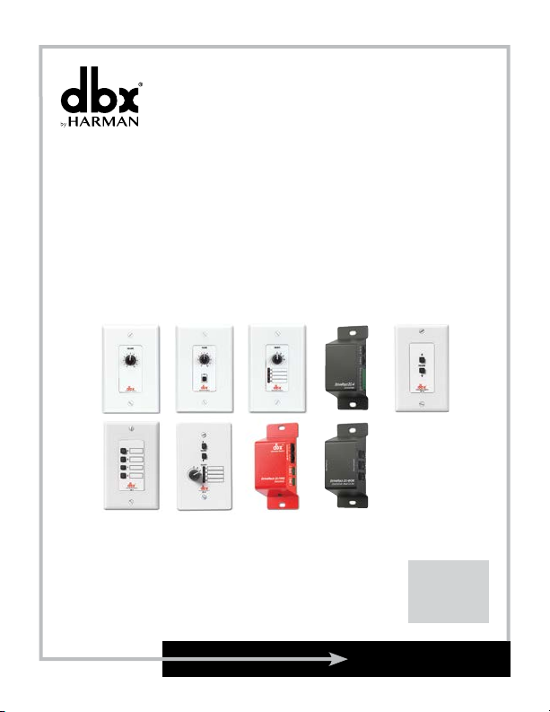
ZC SERIES
Wall-Mounted Zone Controllers
ZC-1-4
ZC-6-9
ZC-Fire
ZC-BOB
User Guide
Page 2
IMPORTANT SAFETY INSTRUCTIONS
The symbol shown to the left is an internationally accepted
symbol that warns of potential hazards with electrical
products. The exclamation point in an equilateral triangle
indicates that it is necessary for the user to refer to the
owner’s manual.
Do not open the unit. Do not attempt to service the unit yourself. Refer
all servicing to qualified personnel. Opening the chassis for any reason
will void the manufacturer’s warranty. Do not get the unit wet. If liquid
is spilled on the unit, shut it off immediately and take it to a dealer
for service.
The following is indicative of low
altitude use; do not use this product
above 2000m.
WARNING FOR YOUR PROTECTION
READ THE FOLLOWING:
READ THESE INSTRUCTIONS.
KEEP THESE INSTRUCTIONS.
HEED ALL WARNINGS.
FOLLOW ALL INSTRUCTIONS.
DO NOT USE THIS APPARATUS NEAR WATER.
CLEAN ONLY WITH A DRY CLOTH.
FOR INDOOR USE ONLY.
DO NOT BLOCK ANY OF THE VENTILATION OPENINGS. INSTALL IN ACCORDANCE WITH THE
MANUFACTURER’S INSTRUCTIONS.
DO NOT INSTALL NEAR ANY HEAT SOURCES SUCH AS RADIATORS, HEAT REGISTERS, STOVES, OR
OTHER APPARATUS (INCLUDING AMPLIFIERS) THAT PRODUCE HEAT.
ONLY USE ATTACHMENTS/ACCESSORIES SPECIFIED BY THE MANUFACTURER.
UNPLUG THIS APPARATUS DURING LIGHTNING STORMS OR WHEN UNUSED FOR LONG PERIODS
OF TIME.
Refer all servicing to qualified service personnel. Servicing is required when the apparatus has
been damaged in any way, such as power-supply cord or plug is damaged, liquid has been spilled
or objects have fallen into the apparatus, the apparatus has been exposed to rain or moisture, does
not operate normally, or has been dropped.
If you want to dispose this product, do not mix it with general household waste. There is a separate collection system
for used electronic products in accordance with legislation that requires proper treatment, recovery and recycling.
Private households in the 25 member states of the EU, in Switzerland and Norway may return their used electronic products free
of charge to designated collection facilities or to a retailer (if you purchase a similar new one).
For Countries not mentioned above, please contact your local authorities for a correct method of disposal.
By doing so you will ensure that your disposed product undergoes the necessary treatment, recovery and recycling and thus prevent
potential negative effects on the environment and human health.
DECLARATION OF CONFORMITY
Manufacturer’s Name: dbx Professional Products
Manufacturer’s Address: 10653 S. River Front Parkway, Suite 300
South Jordan, Utah 84095, USA
declares that the product:
Product name: dbx Zone Controllers Models 1, 2, 3, 4, 6, 7, 8, 9; FIRE and
BOB
Note: Product name may be suffixed by a combination of the letters EU, M, or V.
Product option: None
conforms to the following Product Specifications:
Safety: IEC 60065 -01+Amd 1
EMC: EN 55022:2010 (N/A, analog product)
EN 55013:1990
EN 55020:1991
FCC Part 15 (N/A, analog product)
Supplementary Information:
The product herewith complies with the requirements of the:
Low Voltage Directive 2014/35/EU
EMC Directive 2014/30/EU
RoHS Directive 2011/65/EU
WEEE Directive 2012/19/EU
With regard to Directive 2005/32/EC and EC Regulation 1275/2008 of
17 December 2008, this product is designed, produced, and classified as
Professional Audio Equipment and thus is exempt from this Directive.
C. Rex Reed
Director, Engineering
Signal Processing
10653 S. River Front Parkway, Suite 300
South Jordan, Utah 84095, USA
Date: August 15, 2016
European Contact:
Harman International
Salisbury House
London Wall
EC2M 5QQ
+44 207 562 9450
or
Harman Professional Inc.
10653 S. River Front Parkway, Suite 300
South Jordan, Utah 84095, USA
Ph: (801) 566-8800
Fax: (801) 568-7583
Page 3

CONSIGNES DE SÉCURITÉ IMPORTANTES
Le symbole indiqué à gauche est un symbole internationalement
acceptée qui avertit des dangers potentiels avec des produits
électriques. Le point dans un triangle équilatéral d’exclamation
indique qu’il est nécessaire pour l’utilisateur de consulter le
manuel du propriétaire.
Ne pas ouvrir l’appareil. Ne pas essayer de réparer soi-même l’appareil.
Confier toute réparation à du personnel qualifié. Ouvrir la structure
de l’appareil pour quelque raison que ce soit annulera la garantie du
fabricant. Ne pas mouiller l’appareil. Si du liquide est renversé sur
l’appareil, fermer immédiatement l’appareil et l’apporter chez un
réparateur.
Ce qui suit est représentatif d’une
utilisation à basse altitude ; ne pas
utiliser ce produit au-dessus de 2000 m.
AVERTISSEMENT POUR VOTRE SÉCURITÉ
LIRE ATTENTIVEMENT :
LIRE CES CONSIGNES.
CONSERVER CES CONSIGNES.
RESPECTER TOUS LES AVERTISSEMENTS.
SUIVRE TOUTES LES CONSIGNES.
NE PAS UTILISER CET APPAREIL PRÈS DE L’EAU.
NETTOYER UNIQUEMENT AVEC UN CHIFFON SEC.
POUR USAGE INTÉRIEUR UNIQUEMENT.
NE PAS OBSTRUER LES OUÏES D’AÉRATION. EFFECTUER L’INSTALLATION CONFORMÉMENT AUX
INSTRUCTIONS DU FABRICANT.
NE PAS INSTALLER À PROXIMITÉ DE SOURCES DE CHALEUR TELLES QUE DES RADIATEURS,
BOUCHES D’AÉRATION, PLAQUES CHAUFFANTES OU TOUT AUTRE APPAREIL (Y COMPRIS DES
AMPLIFICATEURS) DÉGAGEANT DE LA CHALEUR.
UTILISER UNIQUEMENT LES PIÈCES/ACCESSOIRES MENTIONNÉS PAR LE FABRICANT.
DÉBRANCHER L'APPAREIL AU COURS DES ORAGES OU EN CAS DE NON-UTILISATION PENDANT
UNE DURÉE PROLONGÉE.
Les réparations doivent être confiées à un technicien S.A.V. qualifié. Une réparation est
nécessaire en cas de dommage quelconque et en particulier en cas d'endommagement du cordon
d’alimentation ou de la fiche électrique, d'infiltration liquide, d'introduction involontaire d'un objet
dans l'appareil, d'exposition de l’appareil à la pluie ou à un milieu humide, de fonctionnement
anormal ou de chute de l'appareil.
Ne pas jeter ce produit avec les ordures ménagères. Il existe un système de collecte sélective pour les produits
électroniques usagés en conformité avec les lois en vigueur en matière de traitement, de récupération et de recyclage.
Dans les 25 États membres de l'UE, en Norvège et en Suisse, les ménages peuvent envoyer leurs produits électroniques
usagés sans frais vers des centres de collecte sélective ou chez un distributeur (contre l'achat d'un nouveau produit).
Contacter les autorités locales pour connaître les procédures de traitement des déchets adaptées dans les pays non
mentionnés ci-dessus.
Non seulement cette précaution vous permettra d’être sûr que votre produit est correctement traité, récupéré et recyclé,
mais elle vous évitera également de nuire involontairement à l'environnement et à la santé humaine.
DÉCLARATION DE CONFORMITÉ
Nom du fabricant : dbx Professional Products
Adresse du fabricant : 10653 S. River Front Parkway, Suite 300
South Jordan, Utah 84095, ÉTATS-UNIS
déclare que le produit :
Nom du produit : dbx Zone Controllers Models 1, 2, 3, 4, 6, 7, 8, 9; FIRE and
BOB
Remarque : Nom du produit peut être suffixé par une combinaison des lettres
de l’UE , M ou V.
Option du produit : Aucune
est conforme aux spécifications suivantes :
Sécurité : CEI/IEC 60065:2001 + Amd 1
CEM : EN 55022:2010 (S/O, produit analogique)
EN 55013:1990
EN 55020:1991
Partie 15 des FCC (S/O, produit analogique)
Informations complémentaires :
Ce produit est conforme aux exigences suivantes :
Directive sur la basse tension 2014/35/UE
Directive 2014/30/UE
Directive RoHS 2011/65/UE
Directive DEEE 2012/19/UE
Ce produit appartenant à la catégorie Matériel audio professionnel, il n’est
pas concerné par la directive 2005/32/CE ou par le règlement européen
1275/2008 du 17 décembre 2008.
C. Rex Reed
Directeur, Ingénierie
Traitement des signaux
10653 S. River Front Parkway, Suite 300
South Jordan, Utah 84095, ÉTATS-UNIS
Date : 15 août 2016
Contactez européenne :
Harman International
Salisbury House
London Wall
EC2M 5QQ
+44 207 562 9450
ou
Harman Professional Inc
10653 S. River Front Parkway, Suite 300
South Jordan, Utah 84095, ÉTATS-UNIS
Tél. : (801) 566-8800
Fax : (801) 568-7583
Page 4

®
®
®
®
®
USER GUIDE
ZC Series Wall Controllers
Zone Controller Wiring
The Zone Controllers, (ZC-1, ZC-2, ZC-3, ZC-4, ZC-6, ZC-7, ZC-8, ZC-9 and ZC-Fire) can be wired serially
or in parallel. To wire in series, each Zone Controller must have an identification or zone number chosen
using the DIP switches on the side of the controller (see diagram A). Each controller must have a unique
number chosen — although there may be multiple Zone Controllers controlling a single zone, or a single Zone
Controller that controls multiple outputs. The Zone Controllers can then be wired together and connected to
the compatible device (e.g., DriveRack
The Zone Controllers may also be wired in parallel with the use of the ZC-BOB. To wire in parallel (home
run cabling), each controller must have a unique identification or number chosen using the DIP switches on
the rear of the panel (see diagram A). To wire in parallel, each controller must be wired into a port of the
ZC-BOB with a connecting wire going to the controlled device (see diagram C). Diagram D shows the typical
wiring for ZC-4 Euroblock connections in which the installer needs to use SPDT (single-pole, double-throw)
switches with one side being connected to 5 volts (+VREF) and the other side to ground (GND). Diagram E
shows the proper way to interface the ZC-Fire to the fire alarm system. Use only the relay/switch closure or
the 5-24V DC inputs. Do not use both inputs at the same time. For information regarding ZC setup, please
see the respective manual for the device that you are setting up.
Diagram A
Diagram B
®
220i, 260, ZonePRO™, etc.) (see diagram B).
RS-232
1
®
Page 5

®
®
®
®
®
Diagram C
ZC Series Wall Controllers
RS-232
USER GUIDE
Diagram D
3 2 1 INOUT
4
+V
ZC-4
corresponds to a switch connected to the ground reference; a “1” corresponds to the switch being connected to
the +V reference. None of the poles should be left hanging but should either be connected to +V or ground.
®
Switches SW1-SW4 correspond to switch inputs 1-4 on the ZC-4’s
EuroBlock connector. Each switch connected to the ZC-4 must
be a Single-Pole Double-Throw (SPDT). One pole of each switch
should be connected to the ground reference on the ZC-4’s
EuroBlock connector while the other pole should be connected
to the +V reference. Because there are four switch inputs, there
are 16 possible switch combinations. In the chart above, a “0”
ZC-4 Binary Appnotes
SW4 SW3 SW2 SW1 Hex Setting
0 0 0 0 0 0
0 0 0 1 1 1
0 0 1 0 2 2
0 0 1 1 3 3
0 1 0 0 4 4
0 1 0 1 5 5
0 1 1 0 6 6
0 1 1 1 7 7
1 0 0 0 8 8
1 0 0 1 9 9
1 0 1 0 A 10
1 0 1 1 B 11
1 1 0 0 C 12
1 1 0 1 D 13
1 1 1 0 E 14
1 1 1 1 F 15
2
Page 6

®
®
®
®
®
USER GUIDE
Connect a normally open or normally closed relay closure
Diagram E
IN
RJ45 - CONNECT ONLY TO
ZONE CONTROLLER INPUT
OUT
ZC Series Wall Controllers
CONTROL
INPUTS
RELAY/
ZC-FIRE
VOLTAGE
SWITCH
5-24 VDC
CLOSURE
Connect a 5-24V DC control voltage to this connector.
Or
to this connector.
Zone Controller Maximum Cable Length
Note - The following cable lengths were achieved using Cat5 Enhanced cable exhibiting a maximum D.C.
resistance of 29 Ohms per 1,000 feet. When connecting Zone Controllers in series, the following cable length
restrictions apply:
• As shown in Diagram F, any (3) Zone Controllers may be wired in series as long as the total cable
length does not exceed 600 feet.
• Any (6) Zone Controllers may be wired in series as long as the total cable length does not exceed 300
feet. Refer to Diagram G.
• Cable runs of up to 1,000 feet may be achieved using “Home Run” wiring. An example of this is
shown in Diagram H. A dbx Zone Controller Break Out Box (dbx ZC-BOB) is used to parallel several
cable runs. It should be noted that a 1,000 foot cable with a single Zone Controller may be connected
directly to the controlled device.
Note - Daisy chaining Zone Controllers to a ZC-BOB (connecting them serially) is not supported or
recommended.
3
®
Page 7

®
®
®
®
®
Diagram F
Diagram G
Diagram H
ZC Series Wall Controllers
RS-232
RS-232
USER GUIDE
RS-232
®
4
Page 8

®
®
®
®
®
USER GUIDE
Cat 5 Cable / 4-Twisted Pairs of 24 AWG Wire
RJ-45
(8-Position)
RJ-45
6
6
6
6
6
6
8 8
Ground
Cable Spec: Cat5 Cable - 4-Twisted Pairs of 24AWG wire
ZC Series Wall Controllers
1 1
2 2
3 3
4 4
5 5
6 6
7 7
Zone Controller Compatibility Chart
DriveRack
ZC-1
ZC-2
ZC-3
ZC-4
ZC-6
ZC-7
ZC-8
ZC-9
ZC-Fire
ZC-BOB
5
DriveRack
220i
X X X X X X
X X X X X X
X X X X X X
X X X X X X
X X X X X X
White / Orange
Orange
White / Green
Blue
White / Blue
Green
White / Brown
Brown
DriveRack
260
4800/4820
(8-Position)
Voltage Reference
ZonePRO
ON
1 2 3 4 5
ON
1 2 3 4 5
ON
1 2 3 4 5
ON
1 2 3 4 5
ON
1 2 3 4 5
ON
1 2 3 4 5
®
Controller 1/7
Controller 2/8
Controller 3/9
Controller 4/10
Controller 5/11
Controller 6/12
ZonePRO
640(M) / 641(M)
X X X X
X X X X
X X X X
X X X
X X X X
1260(M) / 1261(M) SC 32 / 64
Page 9

®
®
®
®
®
ZC Series Wall Controllers
USER GUIDE
Safety Warning
The installation of the Zone Controllers MUST be accomplished with the use of cable which is rated VW-1 or
higher. Common NEC designations which meet this rating include: CMP, CMR, CMG, CM and CMX.
Specifications
Connections: ZC-1, ZC-2, ZC-3, ZC-6, ZC-7, ZC-8 and ZC-9 Connectors: (2) RJ-45
ZC-4 Connectors: (2) RJ-45, (1) 6-Pin Phoenix
ZC-BOB Connectors: (7) RJ-45
ZC-Fire Connectors: (2) RJ-45, (2) 2-Pin Phoenix
Wiring: Maximum cable length depends on number of Zone Controllers and wiring
Series Wiring: Maximum cable length varies with number of Zone Controllers. For
schematic.
example, three Zone Controllers: 600 ft., six Zone Controllers: 300 ft.
Parallel Wiring: Using a ZC-BOB: Up to six Zone Controllers: 1000 ft.
Cable: CAT5 or CAT5E with <28.6 Ohm/M (Ohm/1000 ft.) nominal DCR and
rated VW-1 or higher.
Safety Agency Approvals: UL 60065-07, IEC 60065, EN 55013
Shipping Weight: .7 lb.
®
6
Page 10

®
®
®
®
®
USER GUIDE
[33.0]
[105.7
[7.11]
[15.52]
Dimensions
ZC Series Wall Controllers
ZC-1, ZC-2, ZC-3, ZC-6, ZC-7
]
[66.29]
[83.31]
[96.77]
[24.46]
ZC-8 and ZC-9
[114.3]
7
[69.85]
[83.31]
[22.86] [20.07]
®
Page 11

®
®
®
®
®
ZC Series Wall Controllers
[53.34]
[40.89]
ZC-4, ZC-BOB and ZC-Fire
[120.7]
[133.1]
ZC-1, ZC-2, ZC-3, ZC-6, ZC-7, ZC-8 and ZC-9 EU Models
USER GUIDE
®
8
Page 12

Phone:
Website:
Support:
dbx Professional Products is a registered trademark of HARMAN
(801) 566-8800
dbxpro.com
dbxpro.com/en-US/support
ZC Series User Guide
PN: 5081469-A
© 2016 HARMAN
All rights reserved
 Loading...