

Page 1
Page 2

FOH Application Guide
2
DriveRack™
dbx
Table of Contents
Welcome..................................................................3
Defining the DriveRack™ System..........................3
Applications ............................................................6
Making Connections.............................................10
Crossover Block Diagrams...................................21
Specifications ........................................................26
®
Page 3

Welcome! This application guide has been created to provide you with pertinent information
about the DriveRack™ complete equalization and loudspeaker management system which will in
turn help you optimize the DriveRack™ unit(s) in a Front of House application.
The dbx DriveRack™ Loud Speaker Management System is the most effective way to manage all
aspects of post mix processing and signal routing. The following are just some of the features of
the 480, 481, 482 and 480R DriveRack™ units.
480 DriveRack™ features:
•
4 Input and 8 Outputs with routing
•
31 band graphic or 9 band parametric equalizer on every input (pre-crossover)
•
Dual Real Time Audio Analyzers (on inputs 3&4)
•
Butterworth, Bessel or Linkwitz-Riley crossover filters
•
27 Different Crossover Configurations
•
Time Alignment and Transducer Alignment Delays
•
Compressor/Limiter on every output
•
Speaker Compensation EQ (post crossover)
•
Multi-level Security System
•
Separate House and Show EQ with individual lockouts
•
Triple redundant back up of all parameters when running network, 480R or PC GUI
•
TYPE IV™ Conversion System
•
Electronically balanced/RF filtered XLR Inputs and Outputs
•
Proprietary RS-485 Control Network
•
RS-232 GUI Interface for computer display and configuration
481 DriveRack™ features:
•
4 Input and 8 Outputs with routing
•
31 band graphic or 9 band parametric equalizer on every input (pre-crossover)
•
Dual Real Time Audio Analyzers (on inputs 3&4)
•
Butterworth, Bessel or Linkwitz-Riley crossover filters
•
27 Different Crossover Configurations
•
Time Alignment and Transducer Alignment Delays
•
Compressor/Limiter on every output
•
Speaker Compensation EQ (post crossover)
•
Multi-level Security System
•
Separate House and Show EQ with individual lockouts
•
Triple redundant back up of all parameters when running network, 480R or PC GUI
Defining the DriveRack™ System
FOH Application Guide
DriveRack™
dbx
3
®
Page 4

FOH Application Guide
4
DriveRack™
dbx
•
TYPE IV™ Conversion System
•
Electronically balanced/RF filtered Euroblock Inputs and Outputs
•
Proprietary RS-485 Control Network
•
RS-232 GUI Interface for computer display and configuration
482 DriveRack™ features:
•
4 Input and 8 Outputs with routing
•
31 band graphic or 9 band parametric equalizer on every input (pre-crossover)
•
Dual Real Time Audio Analyzers (on inputs 3&4)
•
Butterworth, Bessel or Linkwitz-Riley crossover filters
•
27 Different Crossover Configurations
•
Time Alignment and Transducer Alignment Delays
•
Compressor/Limiter on every output
•
Speaker Compensation EQ (post crossover)
•
Multi-level Security System
•
Separate House and Show EQ with individual lockouts
•
Triple redundant back up of all parameters when running network, 480R or GUI
•
TYPE IV™ Conversion System
•
Electronically balanced/RF filtered XLR Inputs and Outputs
•
Proprietary RS-485 Control Network
•
RS-232 GUI Interface for computer display and configuration
480R DriveRack™ features:
•
Dedicated remote interface to control all 480, 481 and 482 DriveRack™ units
•
31 Motorized faders for equalization control
•
32 assignable hot-keys with up to 64 different assignment capabilities
•
Built-in Real Time Audio Analyzer (with rear-panel XLR connector)
•
System Mute button
•
Proprietary RS-485 Control Network
•
RS-232 GUI Interface for computer display and configuration
•
480P Power Supply Included
•
Responds to MIDI command from mixing consoles including: Soundcraft™ SM20
and Series 5, Allen & Heath™ ML5000 and Midas™ Heritage
®
Page 5

By including every form of processing necessary to drive the signal from the mixer to the
power amp, the DriveRack™ allows you to eliminate all other processing devices that are normally found in traditional drive rack systems of the past.
The 480 DriveRack™ Loud Speaker Management System includes four balanced XLR inputs,
as well as eight balanced XLR outputs, which can be routed for any configuration. The 481
and 482 DriveRack™ units feature the identical processing power of the 480 DriveRack™, but
utilize streamline front panel interfaces. In addition, the 481 offers euroblock connectors as
opposed to the XLR connectors found in the 480 and 482 DriveRack™.
The 480, 481 and 482 include features such as: pre-crossover EQ, dual RTAs, notch filters,
speaker delays, multiple crossovers, compression/limiting, as well as numerous other features.
Dual RTA analyzers can be run simultaneously with RTA source inputs capable of being remotely switched on the fly. The 480 DriveRack™ is fully programmable from the front panel, and
can control other devices in a network including the 481 and 482. The entire system can be
controlled via the 480R DriveRack™ remote controller or through the included GUI interface.
FOH Application Guide
DriveRack™
dbx
5
®
Page 6

FOH Application Guide
6
DriveRack™
dbx
The following information and illustrations indicate several ways to optimize a DriveRack™ system for use in Front of House systems.
1) Utility amp racks, controller at FOH
With its 4X8 configuration capabilities, the DriveRack™ is the perfect unit for building utility amp
racks. One DriveRack™ and 4 amps in a single rack let you drive anything from a 4 way stereo
module to 4 bi amp boxes all from a single rack. The easiest and most versatile way to do this is
to put the DriveRack™ units in with the amps and then run a controller (480R or GUI) from the
FOH position. A set up such as this can include up to 99 amp racks, and can be controlled from
the FOH position by a single remote, GUI or both. One of the unique advantages of utilizing the
GUI, is its ability to save and recall venues settings. This makes for quick and convenient setups.
The amp racks no longer have to placed in the same position each night. Simply set the ID correctly for each DriveRack™, and the GUI will automatically set up all of the parameters of the previous night. Since you can run 500ft of cable from the remote to the PSU and 4000ft between the
PSU and the first DriveRack™, and another 4000ft between each additional DriveRack™, having
the remote at FOH and the DriveRack™ units with the amps works well in even the largest halls
with out giving up any control. In the shop, the shop tech may want to set the crossovers and
transducer delays and lock them down. The house tech will have access to the House EQ and
use this to flatten the room. The mixing engineer is left with only access to the Show graphic EQ.
In a festival situation, this allows the House tech to flatten the system quickly between each act.
Note that the illustration indicates that left right outputs are run to both sides. This is done to preserve stereo imaging with compressors.
2) Delay towers on the network
When working at large venues, delay towers must be added. By configuring your system with the
utility amps racks mentioned in application 1, delay towers can also be controlled from the FOH
location. With the maximum input delay time of 680 ms, delay towers can be placed up to 770
feet apart. Note that in this application how we have routed the two inputs to the 3-way crossover
and the full-range outputs so that an auxiliary splitter is not required. Because of the networking
capabilities of the units, all the FOH DriveRack™ units and the Delay tower units can be controlled
from a single location.
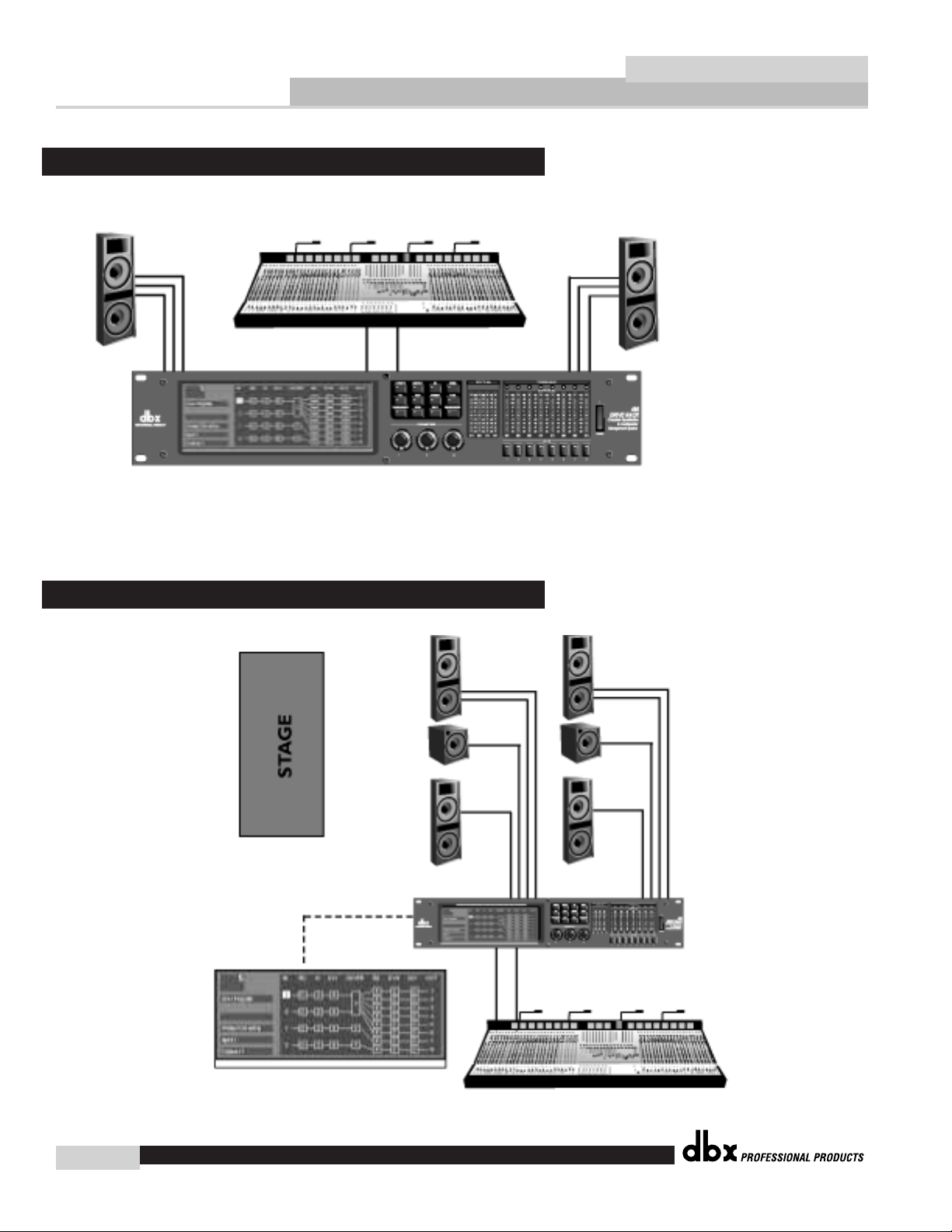
3) DriveRack™ at FOH
For smaller systems (or for systems when no remote is available), a DriveRack™ still works if located at the FOH position. For this application it is best to use a 480 so some level of control is
granted to the operator. However, a 481 or 482 can also be used if no control is needed. Simply
patch out of the console into the DriveRack™, and out of the DriveRack™ to the amps via the
snake to the amps. No other form of processing is needed between the console and the amps.
4) Delay towers from FOH
If a single DriveRack™ can drive a 3-way FOH and two full-range delay towers simultaneously.
With its 4 inputs and 8 outputs, the DriveRack™ will run most systems from a single unit. If two
DriveRack™ units are required, both can be controlled by a master 480.
Applications
®
Page 7
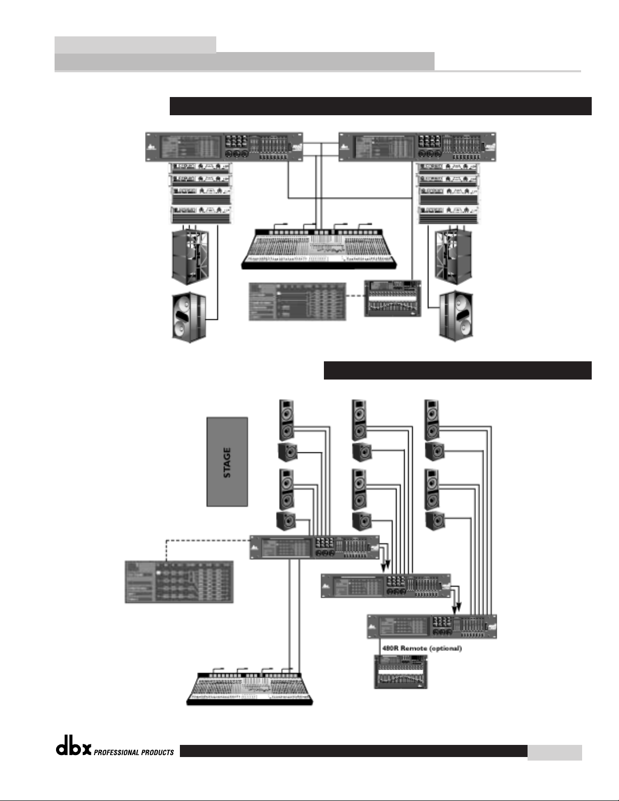
2. Delay Towers on the network
1. Utility Amp Racks (Controller at FOH)
FOH Application Guide
DriveRack™
dbx
7
®
Page 8
FOH Application Guide
8
DriveRack™
dbx
4. Delay Towers from Front of House
3. DriveRack™ at Front of House
®
Page 9
FOH Application Guide
DriveRack™
dbx
9
®
Page 10
FOH Application Guide
10
DriveRack™
dbx
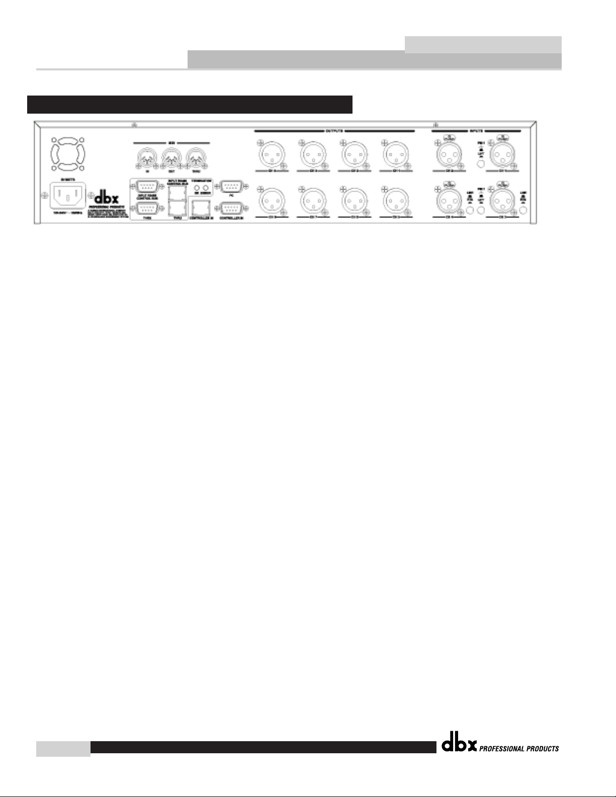
IEC Power Cord Receptacle
The 480 comes with an International power supply that will accept voltages ranging from 100V240V at frequencies from 50Hz-60Hz. An IEC cord is included.
MIDI In and Out/Thru Connectors
These connectors provide MIDI functionality to the 480 DriveRack™. The In, Out and Thru jacks
allow you to use the 480 DriveRack™ at any point in the MIDI chain.
RS485 Control Bus Input (DB-9 connector type)
This input network connection is used to receive information being sent from other units in the
DriveRack™ network link.
RS485 Control Thru Bus (DB-9 connector type)
This Thru network connection is used to pass information to other units in the DriveRack™ network link.
RS485 Control Bus Input (RJ-45 connector type)
This input network connection is used to receive information being sent from other units in the
DriveRack™ network link.
RS485 Control Thru Bus (RJ-45 connector type)
This Thru network connection is used to pass information to other units in the DriveRack™ network link.
Termination LEDs
These LEDS indicate when network is properly terminated. The Green LED indicates that the network has been correctly terminated.
Remote Controller In Connection
This DB-9 type input connection is used to receive information from the 480R Remote Control unit.
RS232 Host Connection
This DB-9 type connection is used to send and receive information to and from the GUI interface.
Outputs 1-8
The output section of the 480 DriveRack™ offers eight electronically balanced XLR connectors.
Rear Panel Connections (480)
®
Page 11

Inputs 1-4
The input section of the 480 DriveRack™ offers four electronically balanced XLR connectors.
Inputs 3 and 4 offer Line/RTA switches that allow you to run a real time audio analyzer microphone directly into the input of the 480 DriveRack™. The four XLR inputs of the 480 Drive also
offer Pin 1 lift switches which lift the ground of the selected XLR input when pressed.
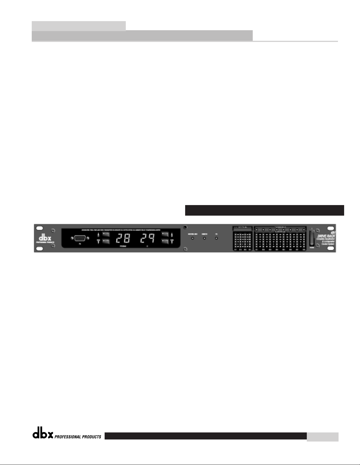
LCD Display
The large LCD display of the 480 DriveRack™ provides the user with all of the vital processing
information of the DriveRack™ including: signal routing, configuration modes, effect block editing
and RTA displays.
Function Buttons
The function buttons of the 480 DriveRack™ allow access to all editing and navigating functions
of the 480 DriveRack™.
Parameter Knobs
The parameter knobs of the 480 DriveRack™ allow the user to edit parameters of selected effects
of the 480 DriveRack™. The parameter knobs of the 480 and 480R DriveRack™ units also incorporate light display Logicators™ which surround the knob itself and indicate levels of parameter
and effect activity. The parameter knobs of the 480 DriveRack™ also provide the user different
modes of functionality including: coarse/fine encoding and horizontal-vertical navigators, which
allow the parameter buttons (when used in program and configuration mode) to navigate the program screen horizontally and vertically.
Front Panel (480)
FOH Application Guide
DriveRack™
dbx
11
®
Page 12

FOH Application Guide
12
DriveRack™
dbx
Input Meters
The 480 DriveRack™ provides the user with four independent 12 segment lightpipe™ input meters that range from -30 to +22 dBu.
Threshold Meters
The threshold meters indicate that the threshold level has been exceeded within the dynamics section (compressor/limiter), and gain reduction
is taking place within the specific output channel.
Output Meters
The 480 DriveRack™ provides the user with eight independent 12-segment lightpipe™ output meters that range from -30 to +22 dBu.
Output Mutes
The eight output mute buttons are used for independently muting each
output on all eight outputs of the 480 DriveRack™.
Power Switch
Turns the 480 DriveRack™ on and off.
IEC Power Cord Receptacle
The 481 comes with an International power supply that will accept voltages ranging from 100V240V at frequencies from 50Hz-60Hz. An IEC cord is included.
RS485 Control Bus Input (DB-9 connector type)
This input network connection is used to receive information being sent from other units in the
DriveRack™ network link.
RS485 Control Thru Bus (DB-9 connector type)
This Thru network connection is used to pass information to other units in the DriveRack™ network link.
RS485 Control Bus Input (RJ-45 connector type)
This input network connection is used to receive information being sent from other units in the
DriveRack™ network link.
RS485 Control Thru Bus (RJ-45 connector type)
This Thru network connection is used to pass information to other units in the DriveRack™ network link.
Rear Panel Connections (481)
®
Page 13
Termination LEDs
These LEDS indicate when network is properly terminated. The Green LED indicates that the network has been correctly terminated.
Remote Controller In Connection
This DB-9 type input connection is used to receive information from the 480 Remote DriveRack™
Unit.
Outputs 1-8 (Euroblock Connectors)
The output section of the 481 DriveRack™ offers eight electronically balanced Euroblock connectors.
Inputs 1-4
The input section of the 481 DriveRack™ offers four electronically balanced Euroblock connectors.
Ground Lift Switch
This switch (when pressed in), is used to lift the Pin one ground on either inputs 1 or 2 or 3 or
4.
RS232 Host Connection
This DB-9 type connection is used to send and receive information to and from the GUI interface.
Program Up and Down
These program up and down buttons are used to scroll through the program menu of the 481.
Program Display
This program display is used to indicate the currently selected program of the 481.
ID Display
This ID display is used to indicate the current assigned identification of the 481. This identification is essential for unit recognition when the 481 is used in a network system.
Control Bus LED
This LED (when lit) indicates that the 481 is sending/receiving network information.
Remote LED
This LED (when lit) indicates that the 481 is sending/receiving from a 480R.
PC LED
Front Panel (481)
FOH Application Guide
DriveRack™
dbx
13
®
Page 14

FOH Application Guide
14
DriveRack™
dbx
This LED (when lit) indicates that the 481 is sending/receiving from a personal computer through
the GUI interface.
Input Meters
The 481 DriveRack™ provides the user with four independent 12 segment lightpipe™ input meters that range from -30 to +22 dBu.
Output Meters
The 481 DriveRack™ provides the user with eight independent 12-segment lightpipe™ output meters that range from -30 to +22 dBu.
Power Switch
Turns the 481 DriveRack™ on and off.
IEC Power Cord Receptacle
The 482 comes with an International power supply that will accept voltages ranging from 100V240V at frequencies from 50Hz-60Hz. An IEC cord is included.
MIDI In and Out/Thru Connectors
These connectors provide full MIDI functionality to the 482 DriveRack™. The In, Out and Thru
jacks allow you to use the 482 DriveRack™ at any point in the MIDI chain.
RS485 Control Bus Input (DB-9 connector type)
This input network connection is used to receive information being sent from other units in the
DriveRack™ network link.
RS485 Control Thru Bus (DB-9 connector type)
This Thru network connection is used to pass information to other units in the DriveRack™ network link.
RS485 Control Bus Input (RJ-45 connector type)
This input network connection is used to receive information being sent from other units in the
DriveRack™ network link.
RS485 Control Thru Bus (RJ-45 connector type)
Rear Panel Connections (482)
®
Page 15

This Thru network connection is used to pass information to other units in the DriveRack™ network link.
Termination LEDs
These LEDS indicate when network is properly terminated. The Green LED indicates that the network has been correctly terminated.
Remote Controller In Connection
This DB-9 type input connection is used to receive information from the 480 Remote DriveRack™
Unit.
RS232 Host Connection
This DB-9 type connection is used to send and receive information to and from the GUI interface.
Outputs 1-8
The output section of the 482 DriveRack™ offers eight electronically balanced XLR connectors.
Inputs 1-4
The input section of the 482 DriveRack™ offers four electronically balanced XLR connectors.
Inputs 3 and 4 offer Line/RTA switches that allow you to run a real time audio analyzer microphone directly into the input of the 482 DriveRack™. The four XLR inputs of the 482 DriveRack™
also offer Pin 1 lift switches which lift the ground of the selected XLR input when pressed.
RS232 Host Connection
This DB-9 type connection is used to send and receive information to and from the GUI interface.
Program Up and Down
These program up and down buttons are used to scroll through the program menu of the 482.
Program Display
This program display is used to indicate the currently selected program of the 482.
ID Display
This ID display is used to indicate the current assigned identification of the 482. This identification is essential for unit recognition when the 482 is used in a network system.
Front Panel (482)
FOH Application Guide
DriveRack™
dbx
15
®
Page 16

FOH Application Guide
16
DriveRack™
dbx
Control Bus LED
This LED (when lit) indicates that the 482 is sending/receiving network
information.
Remote LED
This LED (when lit) indicates that the 482 is sending/receiving from a
480R.
PC LED
This LED (when lit) indicates that the 482 is sending/receiving from a personal computer through the GUI interface.
Input Meters
The 482 provides the user with four independent 12 segment lightpipe™
input meters that range from -30 to +22 dBu.
Threshold Meters
The threshold meters indicate that the threshold level has been exceeded within the dynamics section (compressor/limiter), and gain reduction is taking place within the specific output channel.
Output Meters
The 482 DriveRack™ provides the user with eight independent 12-segment lightpipe™ output meters that range from -30 to +22 dBu.
Output Mutes
The eight output mute buttons are used for independently muting each
output of the 482 DriveRack™.
Power Switch
Turns the 482 DriveRack™ on and off.
®
Page 17

DB-9 and RJ 45 Connectors
Either of these connectors can be used to send and receive information from other DriveRack™
units in the network system.
RTA Microphone Input
This input is used to insert a microphone for use with the real time audio analyzer.
Phantom Power Switch
This Thru network connection is used to pass information to other units in the DriveRack™ network link.
MIDI In and Out/Thru Connectors
These connectors provide MIDI functionality to the 480 DriveRack™. The In, Out and Thru
jacks allow you to use the 480R DriveRack™ at any point in the MIDI chain.
Rear Panel Connections (480R)
FOH Application Guide
DriveRack™
dbx
17
®
Page 18

FOH Application Guide
18
DriveRack™
dbx
LCD Display
The large LCD display of the 480R DriveRack™ provides the user with all of the vital processing information of the DriveRack™ including: signal routing, configuration modes, effect block
editing and RTA displays.
Function Buttons
The function buttons of the 480R DriveRack™ allow access to all editing and navigating functions of the 480 DriveRack™.
Front Panel (480R)
®
Page 19

Parameter Knobs
The parameter knobs of the 480R allow the user to edit parameters of selected effects of the selected DriveRack™. The parameter knobs also provide the user different modes of functionality
including: coarse/fine encoding and etch-a-sketch, which allows the parameter buttons (when
used in program mode) to function navigate the program screen horizontally and vertically.
Network Access Keypad
This 12 button keypad is used to call up any one of the products that are used in a DriveRack™
network set up. Simply enter in the Id number of the device you wish to call up, and then hit the
enter button.
Channel Select Buttons
Instantly recalls the input channel EQ settings of the attached DriveRack™.
Output Mutes
The eight output mute buttons are used for independent output muting on all eight outputs of the
480R DriveRack™.
System Mute Button
The SYSTEM mute button (when pressed and lit) is used to bypass the output signal of any unit
that is used in the DriveRack™ network.
Hot Key Instant Access buttons
The 32 Hot Key buttons can be assigned to instantly access any program screen of any editing
page of any unit used in the DriveRack™ network. Up to 64 different instant access assignments
can be made. To assign a Hot Key instant access button to a selected page, navigate to the screen
page that you wish to assign, and then press and hold the desired Hot Key until the screen flashes. To store over any assigned Hot Key, simply repeat the procedure. Once a hot key has been
assigned, the user does not need recall or remember the individual DriveRack ID number.
FOH Application Guide
DriveRack™
dbx
19
®
Page 20

FOH Application Guide
20
DriveRack™
dbx
Motorized Faders
The 31 motorized faders of the 480R make editing and recalling EQ settings a breeze. The 31
faders control the graphic EQ of the currently selected channel of the selected DriveRack™.
IEC Power Cord Receptacle
The 480P comes with switchable power supply that will accept voltages ranging from 100V-240V
at frequencies from 50Hz-60Hz. An IEC cord is included.
RS485 Link to 480R (DB-9 connector type)
This input connector is used to connect to the 480R.
RS485 Link to Network Master (DB-9 connector type)
This input connector is used to connect 480R to the network master.
RS485 Link to 480R (RJ-45 connector type)
This input connector is used to connect to the 480R.
RS485 Link to Network Master (RJ-45 connector type)
This input connector is used to connect 480R to the network master.
RS232 PC Connection
This input is used to connect a PC to the 480R.
RS485/ PC Select Button
This recessed button is used to select the link to master connector or the PC
Power Switch
Turns the 480P and 480R on and off.
Front Panel (480P)
Rear Panel Connections (480P)
®
Page 21

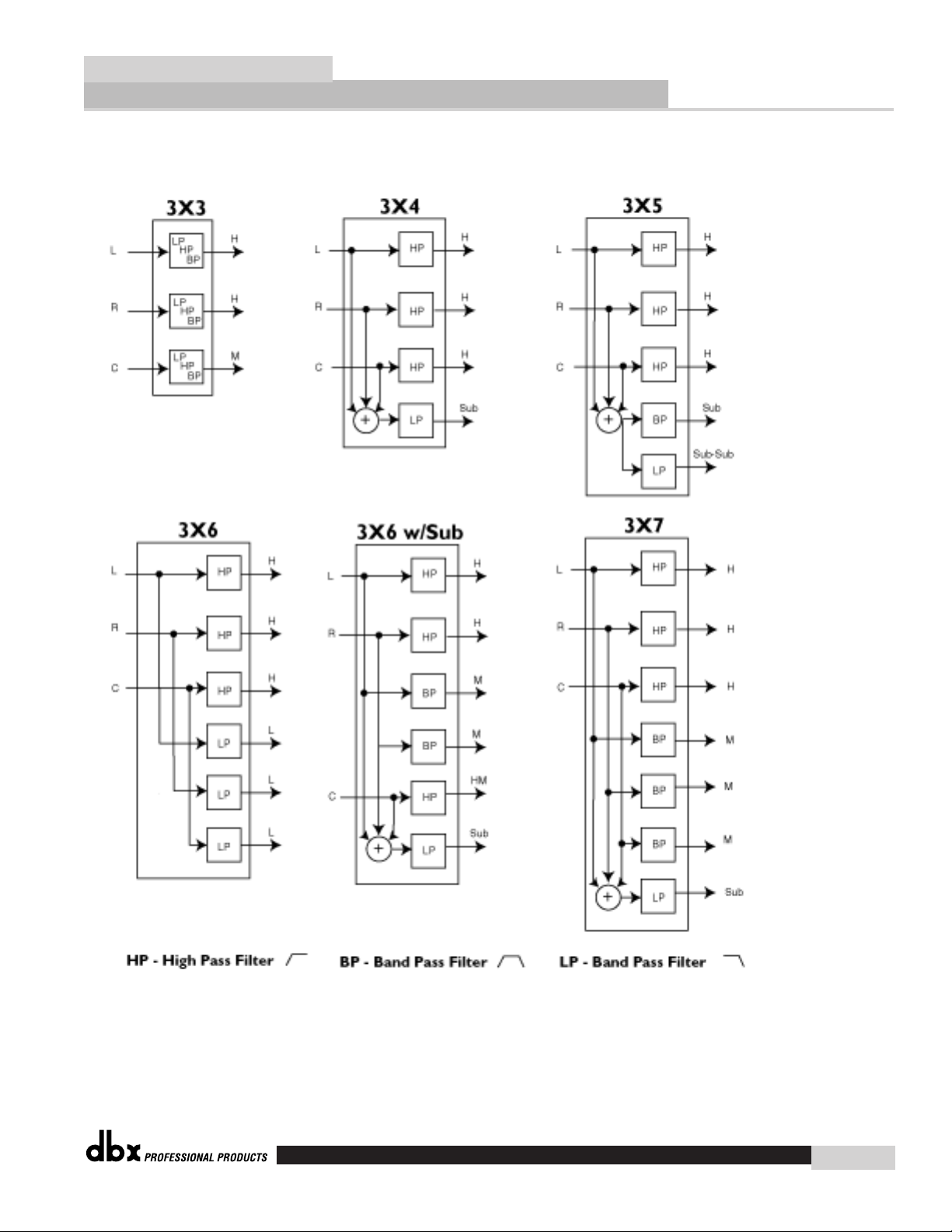
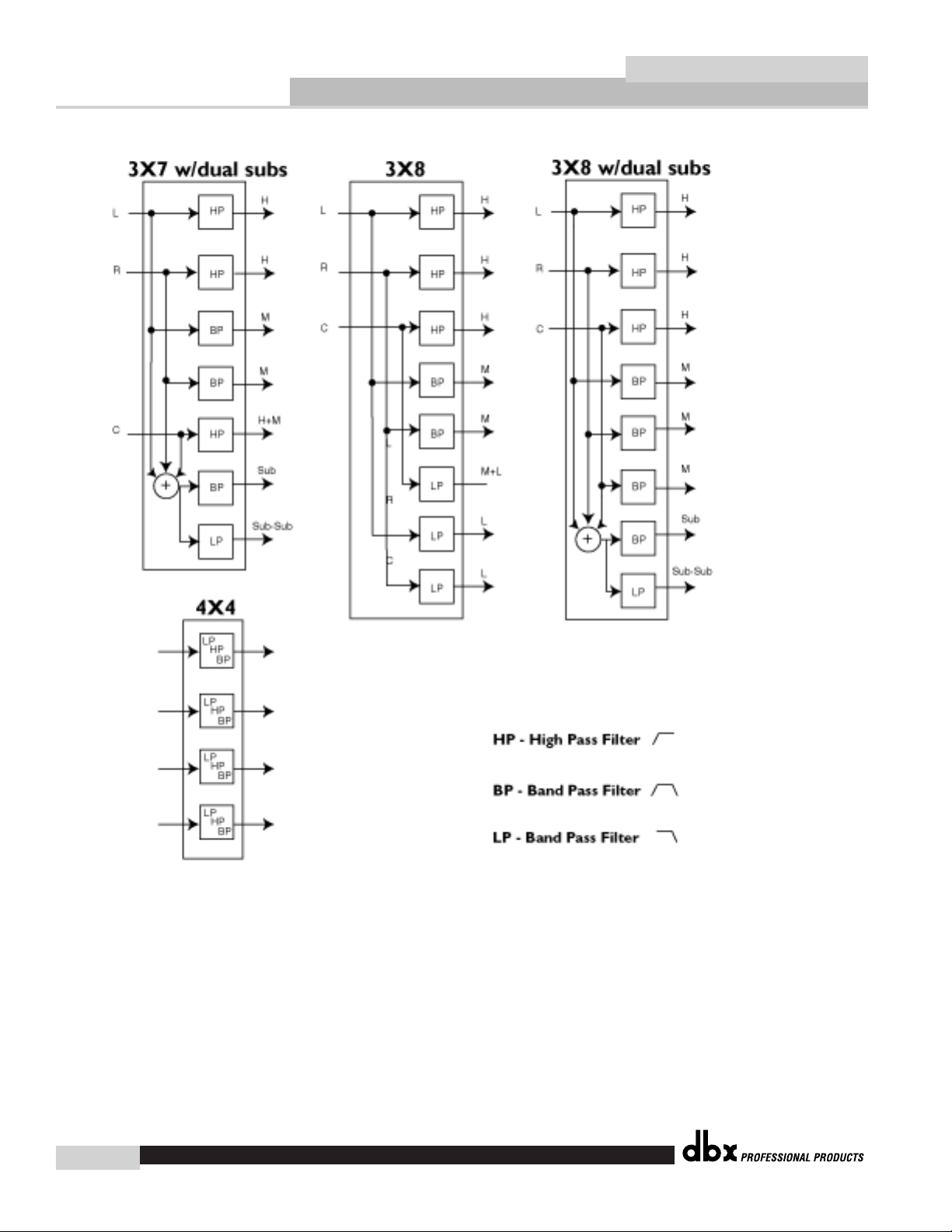
The following are crossover configurations found in the 480, 481 and 482 DriveRack™ units.
Crossover Block Diagrams
FOH Application Guide
DriveRack™
dbx
21
®
Page 22

FOH Application Guide
22
DriveRack™
dbx
®
Page 23
FOH Application Guide
DriveRack™
dbx
23
®
Page 24
FOH Application Guide
24
DriveRack™
dbx
®
Page 25

FOH Application Guide
DriveRack™
dbx
25
®
Page 26

FOH Application Guide
26
DriveRack™
dbx
Specifications ( 480 DriveRack™)
Inputs
Number of Inputs: 4 (Inputs 3 or 4 can be selected as an RTA mic input)
Connectors: Female XLR
Type: Electronically balanced/RF filtered
Impedance: >40kΩ
Maximum Input Level:Hardware selectable for +30, +22, +14, dBu
Max input RTA Level: -10 dBu
CMRR: >40 dB typical, >55 dB at 1kHz
Input Gain Range RTA: 10 dB to 70 dB w/60 dB typical
Outputs
Number of Outputs: 8
Connectors: Male XLR
Type: Electronically balanced, RF filtered
Impedance: 120Ω
Output Transformers: Optional
Max Output Level: +25.5 dBu into 1kΩ
+22dBu into 600Ω
A/D Performance
Type: dbx Type IV™ Conversion System
Dynamic Range line: >112 dB unweighted, 115 dB A-weighted
Type IV™ dynamic range: 127 dB with transient material,
A-weighted, 22kHz BW
125 dB with transient material,
unweighted, 22kHz BW
119 dB typical with program material,
A-weighted, 22kHz BW
Sample Rate: 48kHz
A/D Wordlength: 24 bits
D/A Performance
Dynamic Range: 112 dB unweighted, 115 dB A-weighted
Sample Rate: 48kHz
D/A Wordlength: 24 bits
System Performance
Internal Wordlength: 48 bits
THD + Noise: 0.003% typical at +4dBu, 1kHz,9dB input gain
Frequency Response: 20Hz- 20kHz, +/-0.5dB
Interchannel Crosstalk: <-85dB at 1kHz, 0dB input gain
Pre EQ
Type: One 31-band Graphic EQ per input channel, or
9 band Parametric EQ per input channel
RTA can be substituted for EQ in channels 3 and 4
Range: +/-12 dB range
Notch Filters
Number: 1-5 per input channel not to exceed 10 for all input channels
Pre Delay
Length: 680ms/channel
Crossover
Type: 1x2, 1x3, 1x4,1x5, 1x6
2x3, 2x4, 2x5,2x6, 2x7, 2x8, 3x4,3x5, 3x6, 3x7, 3x8,4x6, 4x8
Filter Type:Butterworth, Bessel, or Linkwitz-Riley
Slope: 6, 12,18 or 24 dB/octave for Butterworth or Bessel filters
12, 24, 36 or 48 dB/octave for Linkwitz-Riley filters
Post EQ
Type: Parametric
Number: 4 EQ bands per output channel
Specifications
®
Page 27

Range: +/-15 dB range
Dynamics
Type: Compressor/Limiter with PeakStopPlus™
Attack/Release: Program Dependent
Linking: All 8 bands are linkable
Post Delay (Driver Alignment)
Length: 170 ms per output channel
Pink Noise Generator
Position: Pink noise inserted on selected input(s)
Phase Compensation
Number: One per output channel
Amount: 0-180 degrees phase shift
Output Polarity: Reversible
Miscellaneous
Output Transformers: Optional
Network: Proprietary RS-485 Backbone
GUI: RS-232 interface for computer display and
configuration
Flying Fader Remote: Optional dbx 480R
RTA Microphone: Optional
ROM Upgrade: Flash upgradeable through RS-232
Dimensions
Dimensions: Height- 3.5” X Width- 19” X Depth 12.15”
Specifications ( 481 DriveRack™)
Inputs
Number of Inputs: 4 (Inputs 3 or 4 can be selected as an RTA mic input)
Connectors: Euroblock
Type: Electronically balanced/RF filtered
Impedance: >40kΩ
Maximum Input Level: Hardware selectable for +30, +22, +14, dBu
Max input RTA Level: -10 dBu
CMRR: >40 dB typical, >55 dB at 1kHz
Input Gain Range RTA: 10 dB to 70 dB w/60 dB typical
Outputs
Number of Outputs: 8
Connectors: Euroblock
Type: Electronically balanced, RF filtered
Impedance: 120Ω
Output Transformers: Optional
Max Output Level: +25.5 dBu into 1kΩ
+22dBu into 600Ω
A/D Performance
Type: dbx Type IV™ Conversion System
Dynamic Range line: >112 dB unweighted, 115 dB A-weighted
Type IV™ dynamic range: 127 dB with transient material,
A-weighted, 22kHz BW
125 dB with transient material,
unweighted, 22kHz BW
119 dB typical with program material,
A-weighted, 22kHz BW
Sample Rate: 48kHz
A/D Wordlength: 24 bits
D/A Performance
Dynamic Range: 112 dB unweighted, 115 dB A-weighted
Sample Rate: 48kHz
D/A Wordlength: 24 bits
FOH Application Guide
DriveRack™
dbx
27
®
Page 28

FOH Application Guide
28
DriveRack™
dbx
System Performance
Internal Wordlength: 48 bits
THD + Noise: 0.003% typical at +4dBu, 1kHz,9dB input gain
Frequency Response: 20Hz- 20kHz, +/-0.5dB
Interchannel Crosstalk: <-85dB at 1kHz, 0dB input gain
Pre EQ
Type: One 31-band Graphic EQ per input channel, or
9 band Parametric EQ per input channel
RTA can be substituted for EQ in channels 3 and 4
Range: +/-12 dB range
Notch Filters
Number: 1-5 per input channel not to exceed 10 for all input channels
Pre Delay
Length: 680ms/channel
Crossover
Type: 1x2, 1x3, 1x4,1x5, 1x6
2x3, 2x4, 2x5,2x6, 2x7, 2x8, 3x4,3x5, 3x6, 3x7, 3x8,4x6, 4x8
Filter Type:Butterworth, Bessel, or Linkwitz-Riley
Slope: 6, 12,18 or 24 dB/octave for Butterworth or Bessel filters
12, 24, 36 or 48 dB/octave for Linkwitz-Riley filters
Post EQ
Type: Parametric
Number: 4 EQ bands per output channel
Range: +/-15 dB range
Dynamics
Type: Compressor/Limiter with PeakStopPlus™
Attack/Release: Program Dependent
Linking: All 8 bands are linkable
Post Delay (Driver Alignment)
Length: 170 ms per output channel
Pink Noise Generator
Position: Pink noise inserted on selected input(s)
Phase Compensation
Number: One per output channel
Amount: 0-180 degrees phase shift
Output Polarity: Reversible
Miscellaneous
Output Transformers: Optional
Network: Proprietary RS-485 Backbone
GUI: RS-232 interface for computer display and
configuration
Flying Fader Remote: Optional dbx 480R
RTA Microphone: Optional
ROM Upgrade: Flash upgradeable through RS-232
Dimensions
Dimensions: Height- 1.75” X Width- 19” X Depth 7.90”
®
Page 29

Specifications ( 482 DriveRack™)
Inputs
Number of Inputs: 4 (Inputs 3 or 4 can be selected as an RTA mic input)
Connectors: Female XLR
Type: Electronically balanced/RF filtered
Impedance: >40kΩ
Maximum Input Level: Hardware selectable for +30, +22, +14, dBu
Max input RTA Level: -10 dBu
CMRR: >40 dB typical, >55 dB at 1kHz
Input Gain Range RTA: 10 dB to 70 dB w/60 dB typical
Outputs
Number of Outputs: 8
Connectors: Male XLR
Type: Electronically balanced, RF filtered
Impedance: 120Ω
Output Transformers: Optional
Max Output Level: +25.5 dBu into 1kΩ
+22dBu into 600Ω
A/D Performance
Type: dbx Type IV™ Conversion System
Dynamic Range line: >112 dB unweighted, 115 dB A-weighted
Type IV™ dynamic range: 127 dB with transient material,
A-weighted, 22kHz BW
125 dB with transient material,
unweighted, 22kHz BW
119 dB typical with program material,
A-weighted, 22kHz BW
Sample Rate: 48kHz
A/D Wordlength: 24 bits
D/A Performance
Dynamic Range: 112 dB unweighted, 115 dB A-weighted
Sample Rate: 48kHz
D/A Wordlength: 24 bits
System Performance
Internal Wordlength: 48 bits
THD + Noise: 0.003% typical at +4dBu, 1kHz, 9dB input gain
Frequency Response: 20Hz- 20kHz, +/-0.5dB
Interchannel Crosstalk: <-85dB at 1kHz, 0dB input gain
Pre EQ
Type: One 31-band Graphic EQ per input channel, or
9 band Parametric EQ per input channel
RTA can be substituted for EQ in channels 3 and 4
Range: +/-12 dB range
Notch Filters
Number: 1-5 per input channel not to exceed 10 for all input channels
Pre Delay
Length: 680ms/channel
Crossover
Type: 1x2, 1x3, 1x4,1x5, 1x6
2x3, 2x4, 2x5,2x6, 2x7, 2x8, 3x4,3x5, 3x6, 3x7, 3x8,4x6, 4x8
Filter Type: Butterworth, Bessel, or Linkwitz-Riley
Slope: 6, 12, 18 or 24 dB/octave for Butterworth or Bessel filters
12, 24, 36 or 48 dB/octave for Linkwitz-Riley filters
Post EQ
Type: Parametric
Number: 4 EQ bands per output channel
Range: +/-15 dB range
FOH Application Guide
DriveRack™
dbx
29
®
Page 30
FOH Application Guide
30
DriveRack™
dbx
Dynamics
Type: Compressor/Limiter with PeakStopPlus™
Attack/Release: Program Dependent
Linking: All 8 bands are linkable
Post Delay (Driver Alignment)
Length: 170 ms per output channel
Pink Noise Generator
Position: Pink noise inserted on selected input(s)
Phase Compensation
Number: One per output channel
Amount: 0-180 degrees phase shift
Output Polarity: Reversible
Miscellaneous
Output Transformers: Optional
Network: Proprietary RS-485 Backbone
GUI: RS-232 interface for computer display and
configuration
Flying Fader Remote: Optional dbx 480R
RTA Microphone: Optional
ROM Upgrade: Flash upgradeable through RS-232
Dimensions
Dimensions: Height- 3.5” X Width- 19” X Depth 12.15”
®
Page 31

Specifications ( 480R Remote Controller DriveRack™)
Inputs
Number of Inputs: 1 Real Time Audio Analyzer
Connectors: Female XLR
Type: Electronically balanced/RF filtered
Impedance: >40kΩ
Max input RTA Level: -10 dBu
CMRR: >40 dB typical, >55 dB at 1kHz
Input Gain Range RTA: 10 dB to 70 dB w/60 dB typical
Miscellaneous
Network: Proprietary RS-485 link
GUI: RS-232 interface for computer display and
RTA Microphone: Optional
ROM Upgrade: Flash upgradeable through RS-232
Dimensions
Dimensions: Height- 12.24” X Width- 19” X Depth 3.20”
Specifications ( 480P Power Supply)
Inputs
Connectors: RS 232 and RS 485 Network Communication Connectors
Dimensions
Dimensions: Height- 1.75” X Width- 19” X Depth 7.90”
FOH Application Guide
DriveRack™
dbx
31
®
Page 32

®
FOH Application Guide
8760 South Sandy Parkway • Sandy, Utah 84070
Phone: (801) 568-7660 • Fax (801) 568-7662 • Int’l Fax:
(219) 462-4596
Questions or comments?
E-mail us at: customer@dbxpro.com or visit our World Wide
Web home page at: www.dbxpro.com
A Harman International Company
 Loading...