

DAVIS Weather Envoy 6314, Vantage Pro Weather Envoy, 6314, 6314C Installation Manual
®
Vantage Pro
Weather Envoy
Installation Manual
Product # 63 14 & 6314C

FCC Part 15 Class B Registration Warning
This equipment has been tested and found to comply with the limits for a Class B digital
device, pursuant to Part 15 of the FCC Rules. These limits are designed to provide reasonable protection against harmful interference in a residential installation. This equipment generates, uses, and can radiate radio frequency energy and, if not installed and
used in accordance with the instructions, may cause harmful interference to radio communications.
However, there is no guarantee that interference will not occur in a particular installation.
If this equipment does cause harmful interference to radio or television reception, which
can be determined by turning the equipment on and off, the user is encouraged to try to
correct the interference by one or more of the following measures:
• Reorient or relocate the receiving antenna.
• Increase the separation between the equipment and receiver.
• Connect the equipment into an outlet on a circuit different from that to
which the receiver is connected.
• Consult the dealer or an experienced radio/TV technician for help.
Davis cables must be used for this equipment to comply with the relevant FCC regulations.Changes or modification not expressly approved in writing by Davis Instruments
may void the warranty and user’s authority to operate this equipment.
Product #: 6314 & 6314C
Part Number: 7395.181
Weather Envoy Installation Manual
Rev A Manual (September 26, 2002)
This product complies with the essential protection requirements of the EC EMC Directive 89/
336/EC..
(c) Davis Instruments Corp. 2002. All Rights Reserved.
3465 Diablo Avenue, Hayward, CA 94545-2778 U.S.A.
E-mail: info@davisnet.com • www.davisnet.com
510-732-9229 • Fax: 510-732-9188

Table of Contents
Table of Contents
Welcome to the Weather Envoy! . . . . . . . . . . . . . . . . . . .1
Contents . . . . . . . . . . . . . . . . . . . . . . . . . . . . . . . . . . . . . . . . . . . . . . . .1
Required for Operation . . . . . . . . . . . . . . . . . . . . . . . . . . . . . . .1
All Weather Envoys: . . . . . . . . . . . . . . . . . . . . . . . . . . . . . . .1
Wireless Weather Envoy: . . . . . . . . . . . . . . . . . . . . . . . . . . .1
Cabled Weather Envoy: . . . . . . . . . . . . . . . . . . . . . . . . . . . .1
Optional Accessories . . . . . . . . . . . . . . . . . . . . . . . . . . . . . .2
Hardware Installation . . . . . . . . . . . . . . . . . . . . . . . . . . . .2
Hardware Requirements . . . . . . . . . . . . . . . . . . . . . . . . . . . . . . . . . . . .2
Local Connection Windows Computer Requirements . . . . . . . .2
Local Connection Macintosh Computer Requirements . . . . . . .2
Preparing the Envoy . . . . . . . . . . . . . . . . . . . . . . . . . . . . . . . . . . . . . . .3
Installing the Data Logger . . . . . . . . . . . . . . . . . . . . . . . . . . . . .3
Installing the Batteries . . . . . . . . . . . . . . . . . . . . . . . . . . . . . . . .4
Connecting AC Power . . . . . . . . . . . . . . . . . . . . . . . . . . . . . . . .5
Connecting a Cabled Envoy to the Integrated Sensor Suite (ISS) 5
Mounting the Envoy . . . . . . . . . . . . . . . . . . . . . . . . . . . . . . . . . .6
Local Computer Installation . . . . . . . . . . . . . . . . . . . . . . . . . . . . . . . . . .7
Installing with a Local Computer . . . . . . . . . . . . . . . . . . . . . . . .7
Remote Computer Installation . . . . . . . . . . . . . . . . . . . . . . . . . . . . . . . .8
Remote Modem Connection Hardware Requirements . . . . . . .8
Installing with a Remote Computer . . . . . . . . . . . . . . . . . . . . . .9
A Few Notes About Phone Modem Connections . . . . . . . . . . . .9
Software Installation and Setup . . . . . . . . . . . . . . . . . . .10
Installing the Software . . . . . . . . . . . . . . . . . . . . . . . . . . . . . . . . . . . . . .10
Windows Computer . . . . . . . . . . . . . . . . . . . . . . . . . . . . . . . . . .10
Macintosh Computer . . . . . . . . . . . . . . . . . . . . . . . . . . . . . . . . .10
Running the Software . . . . . . . . . . . . . . . . . . . . . . . . . . . . . . . . . . . . . .10
Station Setup . . . . . . . . . . . . . . . . . . . . . . . . . . . . . . . . . . . . . . . . . . . . .10
Adding a Station . . . . . . . . . . . . . . . . . . . . . . . . . . . . . . . . . . . .10
About the Walkthrough . . . . . . . . . . . . . . . . . . . . . . . . . . . . . . .11
New Station . . . . . . . . . . . . . . . . . . . . . . . . . . . . . . . . . . . . . . . .12
Station Configuration . . . . . . . . . . . . . . . . . . . . . . . . . . . . . . . . .13
Serial Port . . . . . . . . . . . . . . . . . . . . . . . . . . . . . . . . . . . . . . . . .14
Configure Console . . . . . . . . . . . . . . . . . . . . . . . . . . . . . . . . . . .15
Select Units . . . . . . . . . . . . . . . . . . . . . . . . . . . . . . . . . . . . . . . .16
Set Barometer . . . . . . . . . . . . . . . . . . . . . . . . . . . . . . . . . . . . . .17
i

Table of Contents
Set Rain Cal . . . . . . . . . . . . . . . . . . . . . . . . . . . . . . . . . . . . . . . 18
Set Temp & Hum Cal . . . . . . . . . . . . . . . . . . . . . . . . . . . . . . . . .18
Set Total Rain . . . . . . . . . . . . . . . . . . . . . . . . . . . . . . . . . . . . . . 19
Set Time . . . . . . . . . . . . . . . . . . . . . . . . . . . . . . . . . . . . . . . . . .19
Set Archive Interval . . . . . . . . . . . . . . . . . . . . . . . . . . . . . . . . . .20
Set Latitude and Longitude . . . . . . . . . . . . . . . . . . . . . . . . . . . . 20
Set Alarms . . . . . . . . . . . . . . . . . . . . . . . . . . . . . . . . . . . . . . . . . 22
Auto Download . . . . . . . . . . . . . . . . . . . . . . . . . . . . . . . . . . . . .23
Alarms . . . . . . . . . . . . . . . . . . . . . . . . . . . . . . . . . . . . . . . 24
Three special alarms . . . . . . . . . . . . . . . . . . . . . . . . . . . . . . . . . . . . . . .25
Weather Data Measured & Calculated . . . . . . . . . . . . . . 25
Wind . . . . . . . . . . . . . . . . . . . . . . . . . . . . . . . . . . . . . . . . . . . . . . . . . . . 25
Temperature . . . . . . . . . . . . . . . . . . . . . . . . . . . . . . . . . . . . . . . . . . . . .25
Apparent Temperatures . . . . . . . . . . . . . . . . . . . . . . . . . . . . . . . . . . . . 25
Humidity . . . . . . . . . . . . . . . . . . . . . . . . . . . . . . . . . . . . . . . . . . . . . . . . 26
Dew-Point . . . . . . . . . . . . . . . . . . . . . . . . . . . . . . . . . . . . . . . . . . . . . . .27
Rainfall . . . . . . . . . . . . . . . . . . . . . . . . . . . . . . . . . . . . . . . . . . . . . . . . . 27
Barometric Pressure . . . . . . . . . . . . . . . . . . . . . . . . . . . . . . . . . . . . . . . 27
Solar Radiation . . . . . . . . . . . . . . . . . . . . . . . . . . . . . . . . . . . . . . . . . . .2 8
UV (Ultra Violet) Radiation . . . . . . . . . . . . . . . . . . . . . . . . . . . . . . . . . .28
EvapoTranspiration (ET) . . . . . . . . . . . . . . . . . . . . . . . . . . . . . . . . . . . .31
Leaf Wetness . . . . . . . . . . . . . . . . . . . . . . . . . . . . . . . . . . . . . . . . . . . . 31
Soil Moisture . . . . . . . . . . . . . . . . . . . . . . . . . . . . . . . . . . . . . . . . . . . . .31
Time . . . . . . . . . . . . . . . . . . . . . . . . . . . . . . . . . . . . . . . . . . . . . . . . . . . 31
Troubleshooting Guide . . . . . . . . . . . . . . . . . . . . . . . . . . 32
Communications Problems . . . . . . . . . . . . . . . . . . . . . . . . . . . . . . . . . . 32
Finding the Correct Serial Port . . . . . . . . . . . . . . . . . . . . . . . . . . . . . . .33
Modem Initialization String . . . . . . . . . . . . . . . . . . . . . . . . . . . . . . . . . . 34
Program Problems . . . . . . . . . . . . . . . . . . . . . . . . . . . . . . . . . . . . . . . . 34
Contacting Davis Technical Support . . . . . . . . . . . . . . . . . . . . . . . . . . .35
Specifications . . . . . . . . . . . . . . . . . . . . . . . . . . . . . . . . . . . . . . . . . . . .36
ii
WELCOME TO THE W EATHER ENVOY!
Contents
Welcome to the Weather Envoy!
Welcome to Davis Instruments’ Weather Envoy! The Weather Envoy pr ov ides a
new and exc iting way of getting your Davis weathe r station data into your
Windows (95 or later) or Macintosh (OS X) computer.
The Weather Envoy includes the data collection and logging functions of the Vantage Pro console, but in a smaller package that can be discreetly placed next to
your computer. Both cabled and wireless versions of the Weather Envoy are available. In combination with our WeatherLink software, the Weather Envoy allows
you to view, store, plot, analyze, export, share and print your weather data.
Contents
Before continuing, please be sure your Weather Envoy package includes the
following:
▲ Envoy console
▲ Two #6 x 1” screws for wall mounting
▲ AC-power adapt er
Required for Operation
In order to use your Weather Envoy, you will also need the following Davis
weather products:
All Weather En voys:
▲ WeatherLink for Vantage Pro (Windows version 5.2 or later (#6510C), Mac OS
X version 5.01 or later (#6520C))
Wireless Weathe r Envoy :
▲ Wireless Int eg rated Sensor Suite (ISS) or ISS Plu s
or
▲ Wireless Vantage Pro (Plus) Weather Station
Cabled Weather Envo y:
▲ Cabled ISS or Cabled ISS Plus
1

HARDWARE INS TALLATION
Optional Accessories
Optional Accessories
The following optional accessories are designed for use with your Envoy. They
are available from your dealer or may be ordered directly from Davis.
▲ Telephone Modem Adapter (#6533)
Allows transmission of data from the data logger using a modem.
▲ Standard 4-Conductor 40’ Extension Cable (#7876-040)
For more flexibility in the placement of your Weather Envoy, add one 40’
(12 m) extension cable to extend the distance between your station and the
computer. (48’ (14.4 m) maximum)
Hardware Installation
The Weather Envoy allows two types of installation: local connection to a
computer and remote connection to a computer via a modem. Requirements and
installation for each type of connect ion differ, and are explained separa te ly below.
Hardware Requirements
Note: The amount of storage space necessary for the data files depends on the archive
interval. Each archive record in the database is 88 bytes. Every day in the database
has an additional two records totalling 176 bytes that store daily summary information. A database containing data stored at a 30-minute archive interval requires
approximately 4400 bytes of disk space per day or 132KB of disk space per month.
The disk space requirements change in a linear fashion depending on the archive
interval. For example, data stored at a one-minute interval requires approximately 3.8
MB a month while data stored at a two-hour interval requires approximately 32 KB a
month.
Local Connection Windows Computer Re quirements
Your Weather Envoy requires the following for a local Windows computer
connection:
▲ Computer running Windows™ 95, 98, 2000, XP, ME, or NT 4.0 with at least 5
MB of free disk space
▲ Windows-compatible display
VGA minimum. SVGA or High (16-bit) Color or better recommended.
▲ One free serial port
Local Connection Macintosh Computer Re quirements
Your Weather Envoy requires the following for a local Macintosh computer
connection:
▲ Macintosh computer running Mac OS X v10.01 or newer with at least 5 MB of
free disk space
▲ A USB to serial port converter connected to a Mac in tosh USB port.
2
HARDWARE INSTALLATION
Preparing the Envoy
Preparing the Envoy
Perform the following procedures to prepare your Envoy for operation.
▲ Install the Data Logger
▲ Install the Batteries
▲ Mount your Envoy
▲ Make the Envoy Connections
▲ Test using WeatherLink
▲ Setup the Envoy using WeatherLink
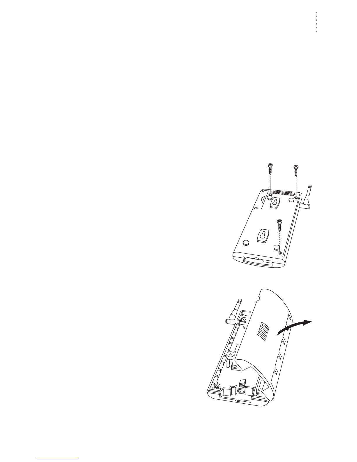
Installing the Data Logger
CAUTION: The WeatherLink data logger must be installed before you install the
batteries!
1. Remove the three screws from the back of the
Envoy case.
2. Separate the case halves to expose
the data logger connector.
3
HARDWARE INS TALLATION
Preparing the Envoy
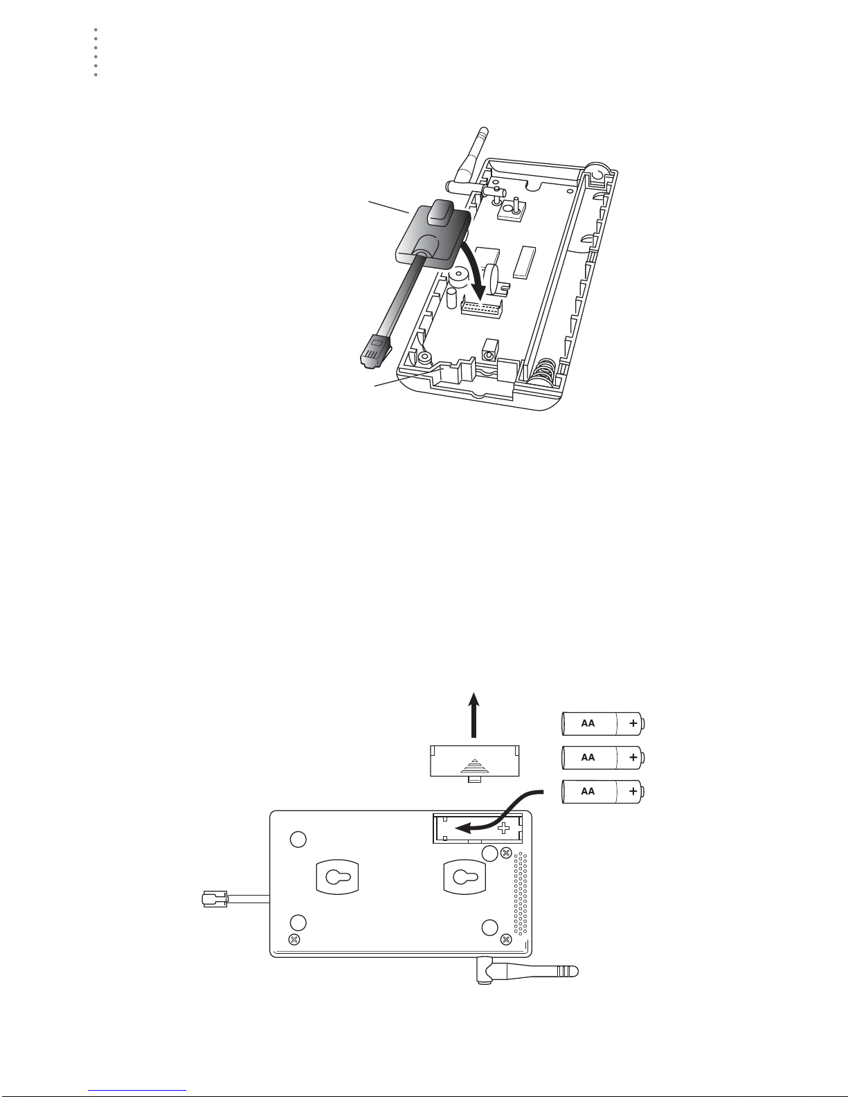
3. Carefully insert the data logger into the connector.
Note:Be sure to push down firmly on the data logger to seat the connection.
Data Logger
Data Logger Cable Channel
Installing the Data Logger
4. Rejoin the case halves, making sure the data logger cable passes through the
cable channel.
5. Fasten using the three screws you previously removed.
Installing the Batteries
CAUTION: The WeatherLink Data Logger must be instal led before you install the
backup batteries!
1. Find th e batte ry cover on the back side of the Envoy case.
2. Remove the battery cover by pressing on the arrow embossed on the cover
and sliding the cover away from the case.
4
Installing the Batteries
HARDWARE INSTALLATION
Preparing the Envoy
3. Insert the three AA-c ell batteries, negati ve terminal (f lat side) fi rst.
The Envoy will run through a brief self-test procedure. If the test is successful
you will hear two (2) beeps.
4. Replace the battery cover on the case.
Note: Operating on battery power alone, the Cabled Weather Envoy will run approximately
10 days and the Wireless Weather Envoy will run approximately 5 months.
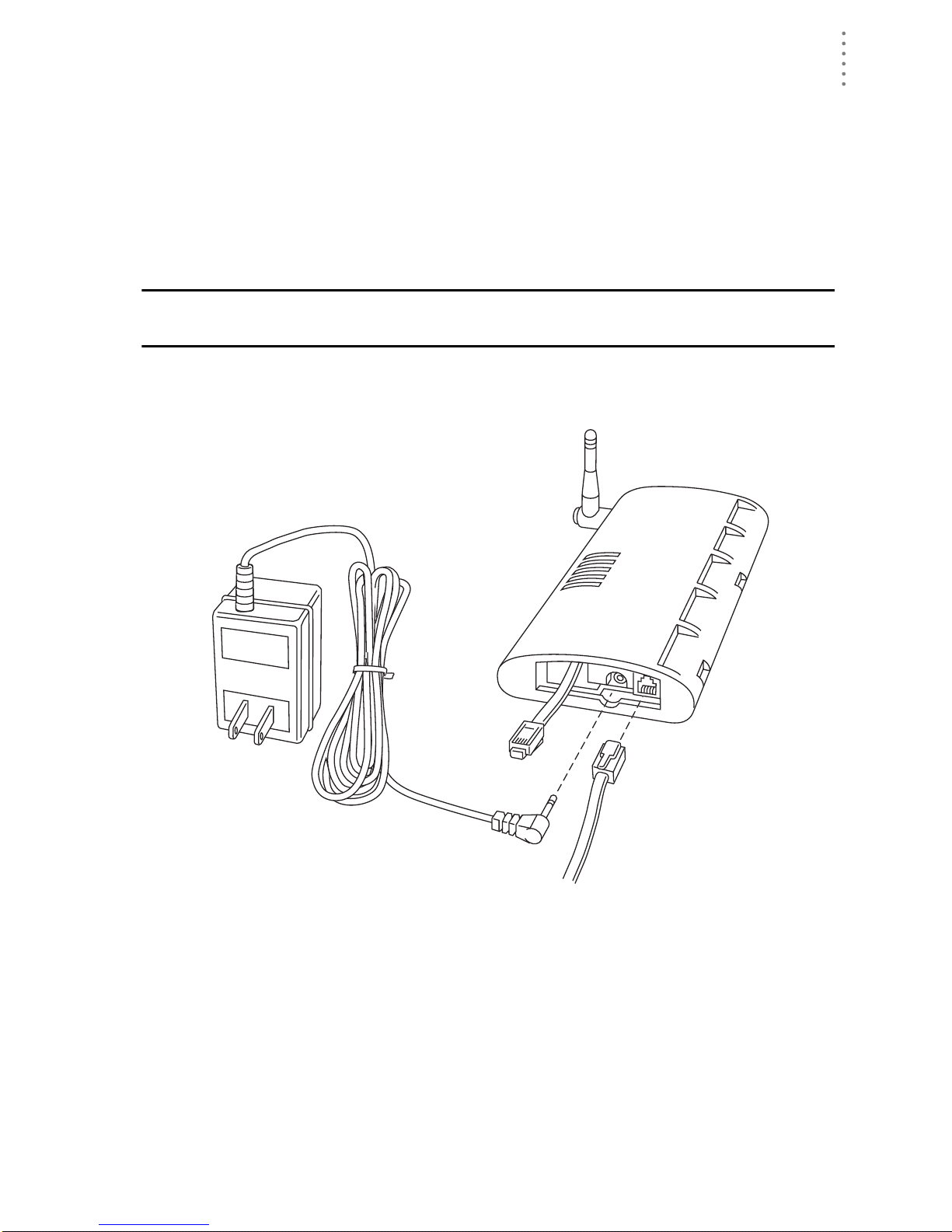
Connecting AC Power
CAUTION: The WeatherLink Data Logger and the backup batteries must be
installed before you connect AC power!
1. Locate the power adapter jack on the end of the Envoy case. It’s next to the
data logger ou tput cable.
Envoy
Data Logger
AC Power
Adapter
2. Insert the power adapter plug into the power jack.
Connecting a Cabled Envoy to the Inte grated Sensor Suite (ISS)
Refer to the figure shown in above “Connecting AC Power”.
1. Insert the modular plug into the ISS j ack on the Envoy cas e.
You won’t be able to tes t the connection between the Envo y and the ISS until
you have finished installing the WeatherLink software.
To
Computer
From Integrated
Sensor Suite
Power
Jack
Power, Sensor, and Computer Connections
(cabled models only)
5

HARDWARE INS TALLATION
Preparing the Envoy
Mounting the Envoy
You can insta ll your Envo y on your desktop or on the wall next to you r compute r.
Note: Whenever you first install the Weather Envoy , place the antenna in a vertical position.
If necessary, you can adjust the angle for best reception after it’s installed.
Use this procedure for a wall installation.
1. Find the template located on the ne xt page.
2. Hold the template against the wall where you want to mount the Envoy, and
use a pencil to mark the location for the two mounting screws.
The screws should be 3.25” (82 .5mm) apart and lined up vert ically.
3. Drill the marked locations with a 3/32” or 7/64” ( 2.2 to 2.7 mm) drill bit.
4. Drive the two #6 x 1” (~ 3.5mm x 25mm) pan head self-threading screws into
the wall.
Leave at least a 1/8” (~ 3mm) space between the wall and the heads of the
screws.
5. Slide the keyholes on the back of the case over the two screw heads.
Wall Mounting the Weather Envoy
#6 x 1"
Pan-Head
Screws
Drill 3/32"
or 7/64"
(~2.2 to 2.7mm)
Holes
3.25"
(82.55mm)
Wall Mounting Template
6
HARDWARE INSTALLATION
Local Computer Install ation
Local Computer Installation
The instructions below explain how to make a typical local connection. Note that
if you extend the cable run beyond 48’ (14.4 m), the software may have difficulty
communicating with the station.
Note: Mac Users - Refer to your WeatherLink for Mac OS X Getting Started Guide for addi-
tional installation instructions.
9-Pin
Connector
(DB-9)
Weather Envoy
Optional 40' (12 m) 4-Conductor
Extension Cable and Coupler
8' (2.5 m) Cable
Data Logger
AC Power
Adapter
Local Computer Installation
Installing with a Lo cal Com puter
1. Locate a free serial port on the back of your computer and connect the DB9 to
the port.
2. Insert the cable plug at the end of the shor t cable coming fr om the data log ger
into the receptacle on the end of the 8’ cable. Then insert the cable plug on the
end of the 8’ cable into the DB9 adapter.
The cable connecting the data logger to the computer is 8’ (2.4 m) long. If you
need to place the station cons ole more than 8’ from the computer, use a 40’ (12
m) standard 4-conductor extension cable (#7876 -040). Do not att empt to use
more than 40’ of extension cable, or the data logger may ha ve difficulty communicating with the computer .
Note: The Weather Envoy data logger does not need to be connected to the computer for
the logging to work. You can connect the cable to the computer when you’re ready to
download, then disconnect it if you want to place the Weather Envoy somewhere
else. However, the WeatherLink bulletin, summary, or real-time strip charts can be
displayed only while the Weather Envoy is attached to the computer.
7
HARDWARE INS TALLATION
Remote Computer Installation
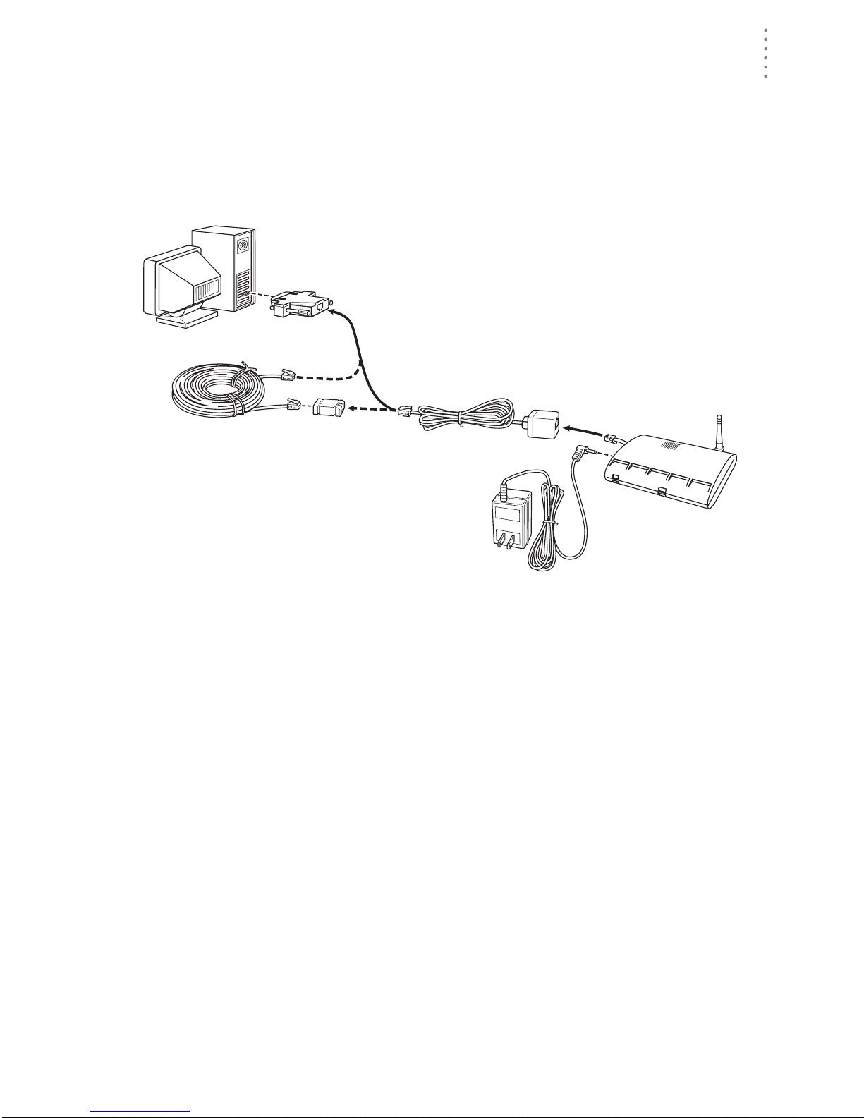
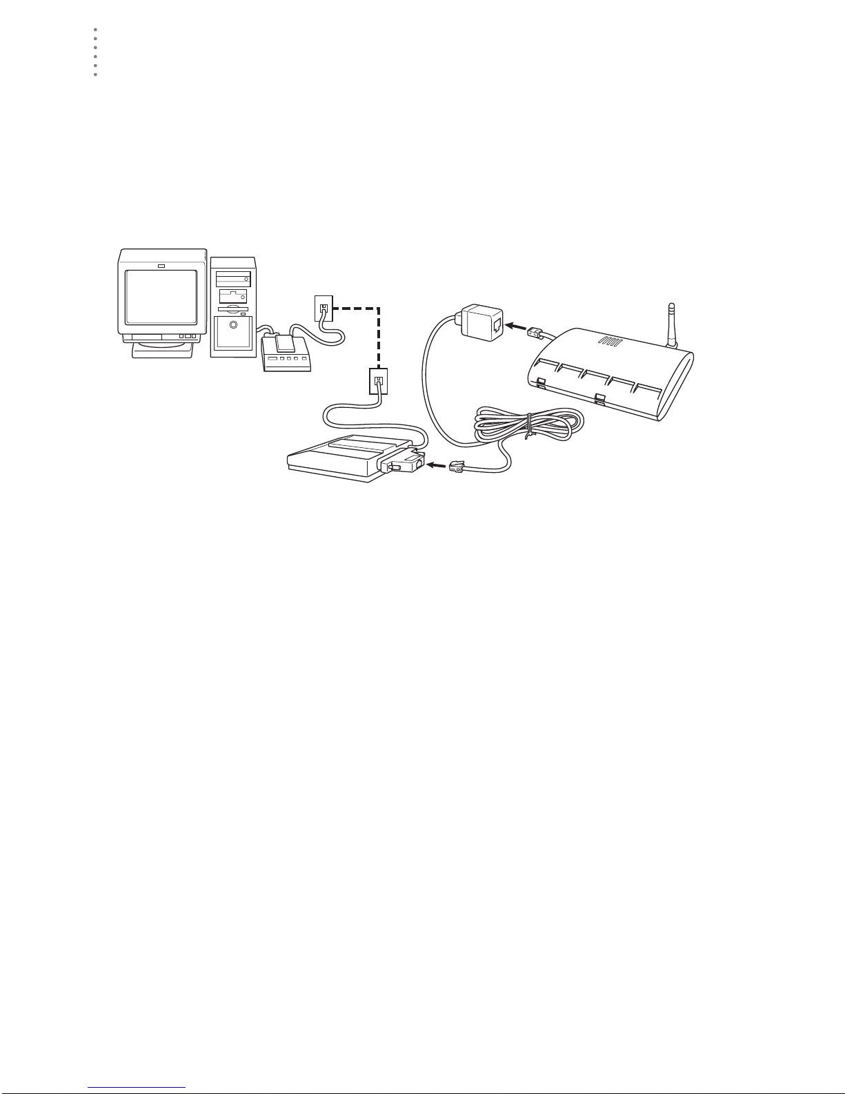
Remote Computer Installation
The illustration below shows a typical remote computer installation using a
modem. This involves connecting the data logger to the Weather Envoy and to a
modem at the station console site and connecting your computer’s modem to a
phone line, which will allow you to dial the Weather Envoy .
Note: Mac Users - Refer to your WeatherLink for Mac OS X Getting Started Guide for addi-
tional installation instructions
Weather Envoy
with Data Logger
Windows Computer
Note: Before installing the console and modem at a remote location, test the data logger
and connection first using a direct connection like that shown in the section above.
External or
Internal Modem
External
Modem
Remote Computer Installation
25-pin Telephone Modem
Adapter (#6533)
8 feet (2.5 m)
Data Logger Cable
(standard)
Remote Modem Connection Hardware Requirements
The following ad ditional hardware is required for a phone modem c onnecti on.
▲ One internal or external modem connected to your computer
The modem must be Hayes®–compati ble and run at 1200, 2400, 4800, 9600,
14400 or 19200 baud.
▲ One external modem to connect to the Weather Envoy data logger
The modem must be Hayes
14000 or 19200 baud.
®
–compati ble and run at 1200, 2400, 4800, 9600,
▲ Telephone Modem Adapter
The Telephone Modem Adapter (#6533) provides the connection between the
Weather Envoy data logger and the modem.
8
 Loading...