


UWR-5-2000-D48E
DATEL UWR-5-2000-D48E, UWR-5-2000-D24E, UWR-5-2000-D12A, UWR-5-1800-D48A, UWR-5-1600-D5A Datasheet
...
Single Output
A-Series, UWR Models
Features
High-Reliability, 2" x 1"
6-10 Watt, DC/DC Converters
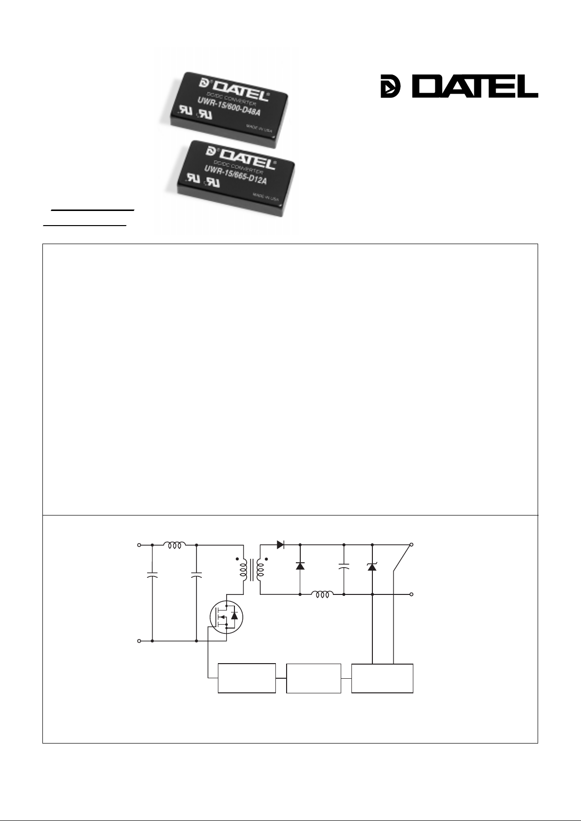
Figure 1. Simplified Schematic
Placing reliability and cost considerations above all others, D A TEL’ s new
A-Series DC/DC Converters combine straightforward circuit topologies, the newest
components, proven SMT-on-pcb construction, and highly repeatable automatic
assembly techniques. Considering the critical low-cost and long-term-reliability
requirements of today’ s telecom, datacom and computer/networking applications, the
A-Series may well be the most cost-effectiv e DC/DC’s av ailable today.
The single-output, 6-10 Watt Models of the A-Series deliver both high power
densities and impressive MTBF’ s. Their superior durability is substantiated by a
rigorous in-house qualification program including HAL T (Highly Accelerated Life
T esting). The goal of HAL T is not to simulate field conditions but to e xpose devices to
multiple excessive stresses with the intention of precipitating any potential electrical,
mechanical or process weaknesses.
Packaged in 2" x 1" x 0.375" shielded metal cases with non-conductive coatings,
these fully isolated (1500Vdc guaranteed) DC/DC’s off er excellent line/load regulation,
full I/O protection, thermal shutdown, and industry-standard pinouts.
Output voltages include 5, 5.2, 12 and 15 V olts. Input voltage ranges are either 4.7-
7.25V ("D5A" models), 9-18V ("D12A" models) or 18-72V ("D48A" models). All A-Series
UWR models are fully EMI characterized and UL1950, CSA950 and IEC950 safety
approved.
A-Series DC/DC’s are extremely reliab le, easy-to-use, cost-eff ective power
converters. Use them to improve the reliability of existing equipment or to develop new
systems that exceed design objectives.
DATEL, Inc., Mansfield, MA 02048 (USA) • Tel: (508)339-3000, (800)233-2765 Fax: (508)339-6356 • Email: sales@datel.com • Internet: www.datel.com
COMMON
+V
OUT
+V
IN
–V
IN
REFERENCE &
ERROR AMP
OPTO
ISOLATION
PWM
CONTROLLER
A- SERIES
■
■■
■■
■
■■
■■
■
■■
■■
■
■■
■■
■
■■
■■
■
■■
■■
■
■■
■■
■
■■
■■
■
■■
■■
■
■■
■■
■
■■
■■
■
Low Cost! Highly reliable!
Proven SMT-on-pcb construction
Designed to meet UL1950 and
EN60950
Qual tested; HAL T tested; EMC tested
Small packages, 2" x 1" x 0.375"
Standard pinouts
5, 5.2, 12 or 15 Volt outputs
Choice of 3 wide-range inputs:
4.7-7.25 Volts
9-18 Volts
18-72 V olts
Fully isolated, 1500Vdc guaranteed
–40 to +100°C operation
5-side metal shielded cases with
non-conductive baseplates
Modifications and customs for OEM’ s
INNOVATION and EX C ELL E N C E
®
®
A Series
6-10W, SINGLE OUTPUT DC/DC CONVERTERS
2
Notes:
For "D5A, D12A and D24E" models,
the case is connected to
pin 2 (–V
IN).
For "D48A and D48E" models, the case
is connected to pin 1 (+V
IN).
Pin
1
2
3
4
5
I/O Connections
Function P11
+Input
–Input
+Output
No Pin
Common
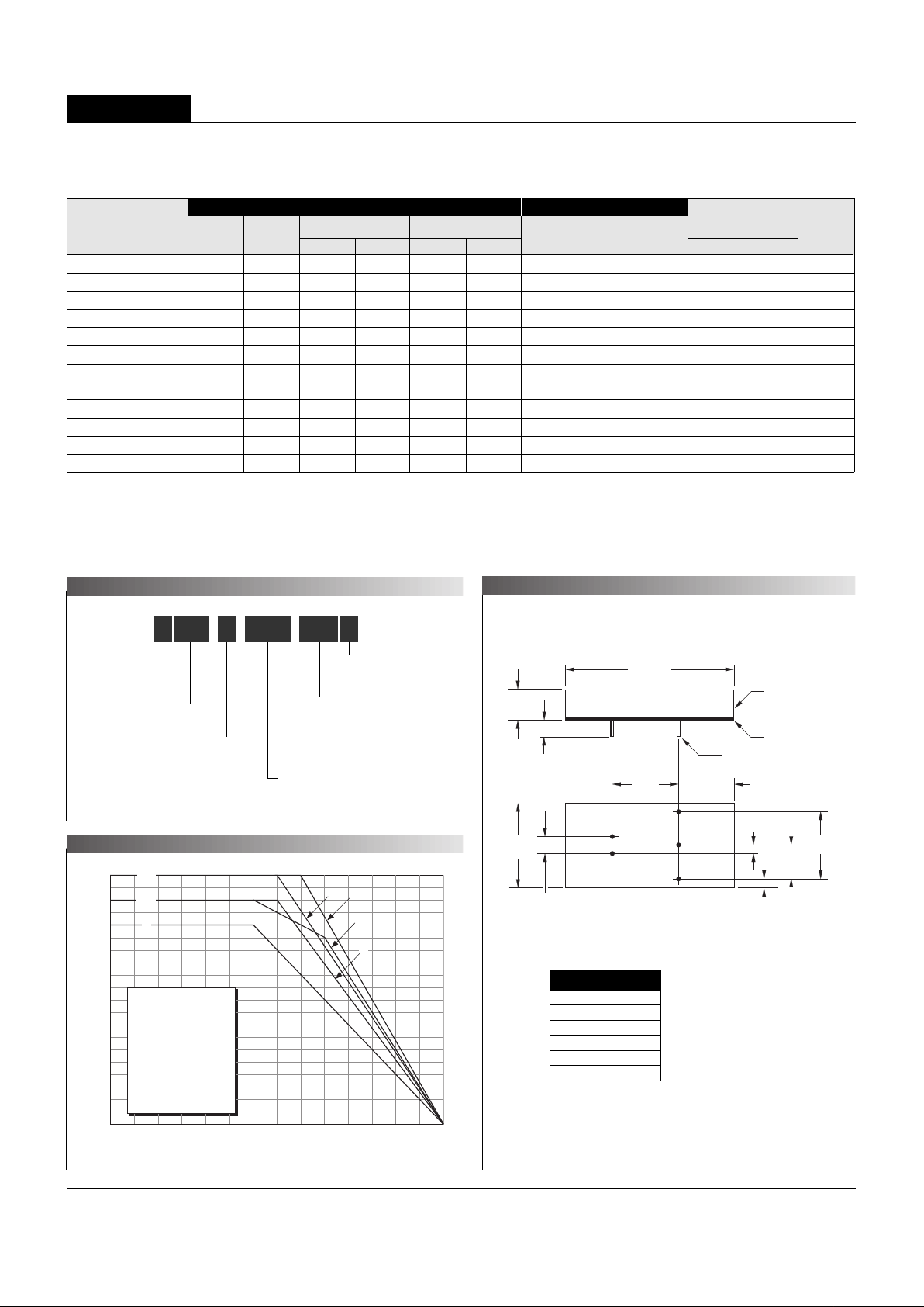
Wide Range Input
Output Configuration:
U = Unipolar
Nominal Output Voltage:
5, 5.2, 12 or 15 Volts
Maximum Output Current
in mA
Input V oltage Range:
D5 = 4.7-7.25 Volts (5V nominal)
D12 = 9-18 Volts (12V nominal)
D24 = 18-36 Volts (24V nominal)
D48 = 18/36-72 Volts (48V nominal)
5U WR 1800-/ D48 A-
A-Series
High Reliability
Output Power (Watts)
Ambient Temperature (°C)
10
9
8
7
6
5
4
3
2
1
0
UWR-5/1600-D5A B
UWR-5/1800-D48A D
UWR-5/2000-D12A C
UWR-5/2000-D24E A
UWR-5/2000-D48E A
UWR-5.2/1500-D5A B
UWR-12/665-D5A B
UWR-12/750-D48A E
UWR-12/830-D12A C
UWR-15/530-D5A B
UWR-15/600-D48A E
UWR-15/665-D12A C
D, E
B
A, C
D
CEA
–40 0 40 45 50 55 60 65 70 75 80 85 90 95 100
Performance Specifications and Ordering Guide
IOUT
(mA)
R/N (mVp-p)
➁
Load
➂
VOUT *
(Volts)
Output
Package
(Case,
Pinout)
Efficiency
Regulation (Max.)
Line
VIN Nom.
(Volts)
Range
(Volts)
Model
Input
➀
T ypical at TA = +25°C under nominal line voltage and full-load conditions unless otherwise noted.
➁
Ripple/Noise (R/N) measured over a 20MHz bandwidth.
➂
10% to 100% load.
➃
Nominal line voltage, no-load/full-load conditions.
➄
See T echnical Notes f or an explanation of trading off input voltage ranges f or higher full-power operating temperature .
IIN ➃
(mA)
➀
Max.
Typ.
Typ.
Min.
UWR-5/1600-D5A 5 1600 50 100 ±0.2% ±0.5% 5 4.7-7.25 20/2105 74% 76% C2, P11
UWR-5/1800-D48A 5 1800 75 100 ±0.2% ±0.5% 48 18-72 10/240 78% 81% C2, P11
UWR-5/2000-D12A 5 2000 50 75 ±0.2% ±0.5% 1 2 9-18 15/1029 79.5% 81% C2, P11
UWR-5/2000-D24E
➄
5 2000 50 75 ±0.2% ±0.5% 24 18-36 10/490 83% 85% C2, P11
UWR-5/2000-D48E
➄
5 2000 50 75 ±0.2% ±0.5% 48 36-72 10/248 82% 84% C2, P11
UWR-5.2/1500-D5A 5.2 1500 50 100 ±0.2% ±0.5% 5 4.7-7.25 20/2053 74% 76% C2, P11
UWR-12/665-D5A 12 6 6 5 75 1 0 0 ±0.2% ±0.5% 5 4.7-7.25 25/2046 75% 78% C2, P11
UWR-12/750-D48A 12 7 5 0 75 1 0 0 ±0.2% ±0.5% 48 18-72 10/230 81.5% 82.5% C2, P11
UWR-12/830-D12A 12 8 3 0 75 1 0 0 ±0.2% ±0.5% 12 9-18 35/988 81% 84% C2, P11
UWR-15/530-D5A 15 5 3 0 50 1 0 0 ±0.2% ±0.5% 5 4.7-7.25 40/2065 75% 77% C2, P11
UWR-15/600-D48A 15 6 0 0 75 1 0 0 ±0.2% ±0.5% 48 18-72 10/233 81.5% 84% C2, P11
UWR-15/665-D12A 15 6 6 5 75 1 0 0 ±0.2% ±0.5% 12 9-18 35/978 82% 85% C2, P11
* Contact DA TEL f or availab lility of 3.3V outputs.
PART NUMBER STRUCTURE
MECHANICAL SPECIFICATIONS
TEMPERATURE DERATING
0.10
(2.54)
0.800
(20.32)
0.60
(15.24)
0.100
(2.54)
1.00
(25.40)
0.400
(10.16)
BOTTOM VIEW
1
2
3
4
5
0.800
(20.32)
METAL CASE
INSULATED BASE
0.040 ±0.002 DIA.
(1.016 ±0.051)
0.20 MIN
(5.08)
0.200
(5.08)
2.00
(50.80)
0.375
(9.53)
Case C2
 Loading...