


Digital Video Switcher
SE-800
INSTRUCTION MANUAL
Http://www.datavideo-tek.com
Table of Contents
Warnings and Precautions … … … … … … … … … … … … … … … … … … … … … … … … … … … … … 3 Warnings and Precautions
Radio and Television Interference Declaration of Conformity
Introduction… … … … … … … … … … … … … … … … … … … … … … … … … .… … … … … … … … … … … 5 Introduction
Product overview
DV format: advantages and limitations What is a switcher?
What is a frame synchronizer? Possible applications
Product Registration Tech Support
What's in the Box… … … … … … … … … … … … … … … … … … … … … … … … … … … … … .… … … … .7
Installation, Connections, Set up… … … … … … … … … … … … … … … … … … … … … … … .… … … ...8 Rear panel Connections
Microphone Inputs and Headphone Jack Some General Notes on Installation Power Up State
Connecting Video sources Connecting Audio sources Outputs and monitor
Using SDI Overlay Interface for CG Text Overlay GPI trigger
RS-232 control
Quick Start… … … … … … … … … … … … … … … … … … … … … … … … … … … … … … … … … … … ...15 Introduction
Sample Application Diagrams
Selecting Video Input formats and Adjusting Audio Levels
Using Video and Audio Monitors Cutting between sources Dissolving between sources Other transitions between sources Effects
Controls and Operations… … … … … … … … … … … … … … … … … … … … … … … … … .… … … … ..22 Front Panel
Video Source
Input Formats Color Processor
RGB color correction
Audio inputs, Levels, and Meters
Audio Input Level Calibration Procedure Voice sync
A+V
1
Using Transitions… … … … … … … … … … … … … … … … … … … … … … … … … … … … … … … … 35
Selecting a Transition: Fade, Wipe, Zoom Playing a Transition Manually
Auto-play
Using the Keypad to customize a transition
Saving effects to Preset Bank
Mode Selects and Use
External trigger using GPI
List of Transitions
Using Effects… … … … … … … … … … … … … … … … … … … … … … … … … … … … … … … … … … 41 Selecting and customizing an effect
Using the Keypad to customize an effect Freeze
Misc, Strobe, Black and White Effects: Mosaic
Effects: Paint
Effects: Picture in Picture Border
Background
Chroma Key
Sample applications… … … … … … … … … … … … … … … … … … ..… … … … … … … … … … … … 45 Production Studio: Cable news/weather show
Multi-camera Shoot: City Council Meeting Live Event Switching: Club VJ
Troubleshooting… … … … … … … … … … … … … … … … … … … … … … … … ...… … … … … … … .49 No power
No image at output Audio clipping
Audio or video feedback Frozen image at output Image distortions etc
Appendix: … … … … … … … … … … … … … … … … … … … … … … … … ...… … … … … … … … … ..50 Glossary of terms
Tech notes (Video Standards, Formats, and Quality; Monitor Calibration) Signal flow schematic
Error Codes
Specifications Useful Accessories
The new functions for unit’s serial number #030500427 and after RS-232 Remote Control Commands
2
Warnings and Precautions
1.Read all of these warnings and save them for later reference.
2.Follow all warnings and instructions marked on this unit.
3.Unplug this unit from the wall outlet before cleaning. Do not use liquid or aerosol cleaners. Use a damp cloth for cleaning.
4.Do not use this unit in or near water.
5.Do not place this unit on an unstable cart, stand, or table. The unit may fall, causing serious damage.
6.Slots and openings on the cabinet top, back, and bottom are provided for ventilation. To ensure safe and reliable operation of this unit, and to protect it from overheating, do not block or cover these openings. Do not place this unit on a bed, sofa, rug, or similar surface, as the ventilation openings on the bottom of the cabinet will be blocked. This unit should never be placed near or over a heat register or radiator. This unit should not be placed in a built-in installation unless proper ventilation is provided.
7.This product should only be operated from the type of power source indicated on the marking label of the AC adapter. If you are not sure of the type of power available, consult your Datavideo dealer or your local power company.
8.Do not allow anything to rest on the power cord. Do not locate this unit where the power cord will be walked on, rolled over, or otherwise stressed.
9.If an extension cord must be used with this unit, make sure that the total of the ampere ratings on the products plugged into the extension cord do not exceed the extension cord’s rating.
10.Make sure that the total amperes of all the units that are plugged into a single wall outlet do not exceed 15 amperes.
11.Never push objects of any kind into this unit through the cabinet ventilation slots, as they may touch dangerous voltage points or short out parts that could result in risk of fire or electric shock. Never spill liquid of any kind onto or into this unit.
12.Except as specifically explained elsewhere in this manual, do not attempt to service this product yourself. Opening or removing covers that are marked “Do Not Remove” may expose you to dangerous voltage points or other risks, and will void your warranty. Refer all service issues to qualified service personnel.
13.Unplug this product from the wall outlet and refer to qualified service personnel under the following conditions:
a.When the power cord is damaged or frayed;
b.When liquid has spilled into the unit;
c.When the product has been exposed to rain or water;
d.When the product does not operate normally under normal operating conditions. Adjust only those controls that are covered by the operating instructions in this manual; improper adjustment of other controls may result in damage to the unit and may often require extensive work by a qualified technician to restore the unit to normal operation;
e.When the product has been dropped or the cabinet has been damaged;
f.When the product exhibits a distinct change in performance, indicating a need for service.
3

Radio and Television Interference
UNITED STATES: The equipment described in this manual generates and uses radio frequency energy. If it is not installed and used in accordance with the instructions in this manual, it may cause interference with radio and television reception.
This equipment has been tested and found to comply with the limits for a Class B digital device, pursuant to Part 15 of the FCC Rules. These limits are designed to provide reasonable protection against harmful interference in a residential installation. This equipment generates, uses, and can radiate radio frequency energy, and if not installed and used in accordance with these instructions, may cause harmful interference to radio communications. However, there is no guarantee that interference will not occur in a particular installation. If this equipment does cause harmful interference to radio or television reception, which can be determined by turning the equipment off and on, the user is encouraged to try to correct the interference by one or more of the following measures:
1.Reorient or relocate the receiving antenna;
2.Increase the separation between the equipment and the receiver;
3.Connect the equipment into an outlet on a circuit different from that to which the receiver is connected.
If necessary, consult your dealer or an experienced radio/TV technician for help and/or additional suggestions. You may find the following booklet helpful: How to Identify and Resolve Radio-TV Interference Problems, booklet number 004-000-00345-4, prepared by the Federal Communications Commission. It is available from the United States Government Printing Office, Washington D.C. 20402.
Note: Changes or modifications not expressly approved by the party responsible for compliance could void the user’s right to operate this equipment.
Peripherals used in conjunction with this equipment must be connected via shielded interface cables. Use of unshielded interface cables may result in interference to radio and TV reception, and may void the user’s right to operate this equipment.
Declaration of Conformity
Model Number: SE-800
Trade Name: Datavideo
Responsible: Datavideo Corporation (USA)
Address: 12300-U East Washington Blvd., Whittier CA 90606, USA
Telephone: (562) 696-2324
This device complies with Part 15 of the FCC Rules. Operation is subject to the following two conditions:
1.This device may not cause harmful interference.
2.This device must accept any interference received, including interference that may cause undesired operation.
4
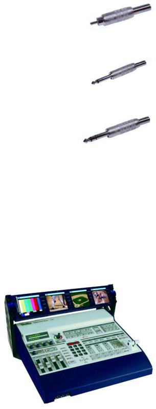
Introduction
Thank you for purchasing Datavideo’s SE-800 Digital Video Switcher. We think you will be amazed and pleased at what you can do with this advanced piece of technology. In order to get the most out of your new switcher, we recommend that you spend some time getting familiar with this manual, as it will describe in detail all the functions of this unit. In addition, you’ll find some useful background information on video and audio, and some detailed examples of ways to use your new switcher.
You might want to immediately take a look at the Quick Start section on page 15 for a quick overview.
Product Overview
Now you can shoot, mix, and edit, all within the DV25 format. Datavideo SE-800 is a 4 input channel digital switcher, featuring four multi-format inputs for each channel (your choice of DV (DV25), Component YUV, S- video (Y/C), or Composite video) and an SDI Overlay port that will allow you to use your PC as a character generator and/or graphics source. The full size control panel includes 30 user programmable macro function keys that let you play back preset transitions and effects instantly by pressing a single key.
Built in high quality Datavideo format converters provide simultaneous analog and digital audio and video outputs. A Dual channel TBC with YUV 4:2:2 Frame synchronizer for Composite, S (Y/C) and Component Y.U.V. inputs and outputs assures stable and high quality video from virtually any source. The SE-800 can serve as a sync reference for analog cameras, video projectors, scan converters, etc.
A built in R.G.B. Color Processor and a Color Corrector for each input video, with settings that are saved, allow you to fine tune your video. Programmable digital effects include A/B Rolls, A/B Dissolves, ChromaKeying, Mosaic, Picture in Picture, Strobe, Fades, and Wipes.
A four stereo input mixer with stereo microphone inputs and automatic Audio follow Video switching can take care of most any audio needs.
The RS-232 Control Port enables a remote control front panel thru PC-RS232 port or connection of the Datavideo RMC-90. SDI ports for serial digital video connect to an expansion PC SDI graphics card for video overlays of text and graphics from a PC.
The SE-800 comes complete with a carrying case for increased protection in the field.
What is a switcher?
A switcher is something or someone that allows or facilitates switching.
In this case, the switching that happens is among 4 video and 7 audio sources. And if just switching were the only requirement, then this piece of equipment would be like a row of light switches. But no: to be truly useful in a production environment, a video switcher has to provide for numerous ways to go from one video source to another (transitions), ways to adjust the look of the video (color processor and special effects), to deal with audio, and to keep the whole thing synchronized, looking good.
5
What is a frame synchronizer?
A frame synchronizer is a digital device that stores a frame of video in its memory and releases it at a very precise moment. These little devices are essential if you want to make a seamless switch from one video source to another. If the sources you are switching between are not synchronized with each other, the video image falls apart at the transition moment, and the result is not pretty.
The SE-800 has a full frame synchronizer (also known as a time base corrector or TBC) at its Main and Sub Source inputs (2 total) to insure switches without distortion and smooth, well-regulated video at its output. In addition to its digital memory, a TBC also has controls that affect the look of the video that passes through it. These controls are known as processing amplifiers, or proc amps; they control brightness, contrast, color, and tint, though these may have different names in different applications.
For more information on some of these technical aspects, see the Appendix Tech Notes on page 53
Possible applications
You may already have some uses in mind for the SE-800. There’s a real good chance that by browsing through this manual, you will find some applications you didn’t think of or expect. Take a look at the Sample Applications section (page 45); we describe 3 sample uses for the SE-800: a cable weather/news show, a city council meeting, and a club video performance.
Product registration
Go on line www.datavideo-tek.com/product_reg.htm for product registration
See the warranty card for warranty period
REGISTRATION CARD QUESTIONS
SE-800 REGISTRATION CARD – Please return this card for product warranty registration
Serial Number:
Where did you purchase:
Your name:
Your mailing Address:
Email address:
May we include you in our mailing list to learn about new Datavideo products? Yes/no
Why did you buy the SE-800?
What video editing software programs do you use?
What computer platforms and operating systems do you use?
Do you have a COMPONENT video recorder or player?
What video sources will you use with the SE-800?
Where will you use your SE-800?
6
Tech support
Datavideo maintains three offices worldwide to support this and other products.
Datavideo Technologies Co., LTD.
7F, No. 352, Sec. 2, Chung Shan Rd
Chung Ho City, Taipei Hsien, Taiwan R.O.C.
Tel: 886-2-2246-7979
Email: info@datavideo.com.tw
Datavideo Corporation USA
12300-U East Washington Blvd.
Whittier CA 90606 USA
Tel: (562) 696-2324
Email: contactus@datavideo-tek.com
Datavideo Technologies Europe BV
Californiedreef 26
3565 BL Utrecht, the Netherlands
Tel: +31 30 261 9656
Email: info@datavideo.nl
Datavideo Technologies China Co.
2F-D, No 2, Lane 777, West Guang-zhong Rd Zhabei District, Shang-Hai, China
Tel: 86 21 5603-6599 Email: info@datavideo.cn
What’s in the box?
1.AC / DC Power Adaptor * 1
2.AC Cord * 1
3.Carrying Case * 1
4.1.8M IEEE 1394 Firewire 6 to 4 Cable * 2 (Not equipped for SE-800 AV)
5.0.3M IEEE 1394 Firewire 6 to 4 Cable adaptor * 4 (Not equipped for SE-800 AV)
6.1.2M S-Video Cable * 2
7.GPI Cable * 1
8.Instruction Manual * 1
7
Installation, Connections, Set up
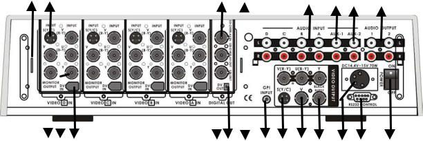
Rear Panel Connections
1b |
1a |
2 |
3 |
6 |
7 |
8 |
9 |
|||||
|
|
|
|
|
|
|
|
|
|
|
|
|
|
|
|
|
|
|
|
|
|
|
|
|
|
|
|
|
|
|
|
|
|
|
|
|
|
|
|
|
|
|
|
|
|
|
|
|
|
|
|
|
|
|
|
|
|
|
|
|
|
|
|
|
1c 1d 1e |
4 |
5 |
11a |
10 |
11b 11c 11d |
12 |
13 |
14 |
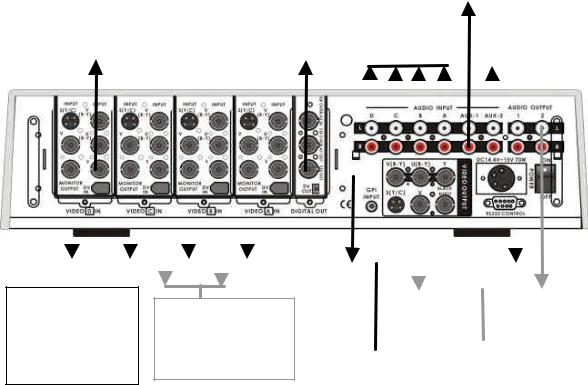
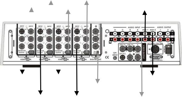
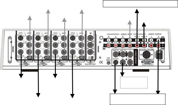
1.Video inputs, Channels A, B, C, D. 1a. S-Video (Y/C) input
1b. Composite video input (BNC)
1c. Monitor output, composite video (BNC)
1d. Component (YUV) video inputs (BNC)
1e. DV input (Firewire 6-pin with cable power 14.5VDC)
2.SDI (SMPTE 259M) Overlay input (BNC)
3.SDI (SMPTE 259M) Overlay out (BNC)
4.SDI (SMPTE 259M) Out (BNC)
5.DV output (Firewire 6-pin with cable power 14.5VDC)
6.Audio line inputs, channels A, B, C, D (RCA)
7.Stereo Aux-1 audio inputs (RCA)
8.Stereo Aux-2 audio inputs (RCA)
9.Two Stereo Audio outputs (RCA)
10.GPI input
11.Video outputs
11a. Component (YUV) video out (BNC)
11b. S-video (Y/C) out
11c. Composite video out (BNC)
11d. Black burst out (BNC)
12.DC Power input 15V 4.5A
13.RS-232 Control
14.Power switch
8
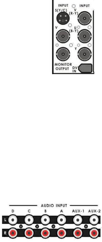
1.Video In (Channels A, B, C, and D are all set up the same way)
a.S-Video (Y/C) input: takes a standard 4 pin S-video cable from the output of a VCR, camera, DVD player, etc.
b.Composite video input: takes a BNC connector from the composite output of a VCR, camera, DVD player, etc.
c.Monitor output: Even though this is in the input section, it is a composite video output, using a BNC connector of whatever signal is present at the selected input of that channel (using the Input Format selectors on the front panel, page 8). Connect this output to a video monitor for use as a preview.
d.Y.U.V. input: This input takes analog component video (Y.U.V.) into the switcher through 3 BNC connectors. (See Connecting
Video Sources for more information on connecting these ports to a device.)Most DVD players these days, for example, have analog component outputs (in addition to composite and S-video); these outputs are found on Betacam, DVCPro, and DVCam decks.
e.DV in: 6-pin DV (a.k.a. FireWire, iLink, IEEE 1394) cable, from the DV port of a camcorder, DV Bank, DV deck, etc.
Note: Please don’t connect the S (Y/C) and YUV cable to video input jacks at same time.
2.SDI Overlay In: BNC connector for bringing in a Serial Digital video signal from a computer graphics card, which will automatically be overlaid on the output mix of the SE-800. For more information, see Using SDI, page 14.
3.SDI Overlay Out: BNC. For more information, see Using SDI, page 14.
4.SDI Out: BNC connector carrying the serial digital video output signal of the SE800 to SDI equipment such as TV wall, .SDI Video Recorder.
5.DV Out: 6 pin DV connector carrying the DV version of the Video output signal of the SE-800.
6.Audio Inputs: a stereo pair of RCA connectors for each line level, unbalanced analog audio signal associated with each input channel.
7.Aux 1/2 (Music): Two RCA stereo pair for a line level auxiliary analog audio
source, such as a CD player or tape deck.
9
8.Audio Output: Two RCA stereo pairs of line level analog audio, carrying the signal present at the output of the audio mixer section (see Controls and Operations, page 22).
9.GPI input: 1/8-inch (3.5mm) mini jack for remote trigger control. For more information, see GPI Trigger and
External Trigger Using GPI on page 14.
10.Video Output. These ports carry the Main video output of the SE-800.
a.Y.U.V. video out: These BNC connectors carry the analog component Main video signal, and would typically be connected to a master recorder (Betacam, DVCPro, or DVCam, for example), component video monitor, or a satellite uplink. (See Connecting Video Sources, page
12 for more information on connecting these ports to a device.)
b.S-video out: standard 4 pin S-video (Y/C) connector, typically connected to a VCR, projector, or monitor.
c.Composite video out: BNC connector, typically connected to a program monitor.
d.Black Burst out: BNC connector carrying a black burst signal (derived from the SE-800’s internal TBCs), used to provide a sync source to any video devices connected to the SE-800 that may require sync for proper operation.
11.Power: Operate this gently with a slight flourish.
12.RS-232 control: Please read the Appendix of RS-232 Protocol on page 67 for more information.
13.DC Input: connect the power supply that came with the SE-800, and only the power supply that came with the SE-800, here, and plug the other end into an electrical outlet, preferably on a surge suppressor (to protect the SE-800 from random power spikes that can fry its delicate insides).
15.MIC inputs L and R: accepts 1/4 Inch mono plugs, carrying high impedance signals from one or two mono
microphones. With high impedance MIC, the longer the cable from microphone to the SE-800, the more noise is introduced into the signal. If you are using an audio mixer (to combine more than two sources),
connect the mixer’s line level output to the SE-800’s Aux inputs.
10
16.Headphones: accepts a stereo 1/4 inch plug for stereo headphones. The signal present at the Headphones jack is controlled by the Headphone controls switches and level on the front panel. For more information, see Controls and Operations page 22 and Output and Monitor, page 13.
Some General Notes on Installation
There are a few other things to be aware of when you are installing and integrating the SE-800. Please make sure you have read the Warnings and Precautions section on page 3.
The SE-800 sends and receives both analog and digital signals. Digital signals are carried through the DV and SDI cables; all the rest (except the GPI, RS-232 connections) are analog. One of the beauties of digital is that most of the cautions described below, regarding cable lengths, impedance, crossing power cords, and adaptors, are not an issue. The cautions below, with the exception of physical damage, apply only to cables carrying analog video or audio.
It is quite possible these days to buy whatever cable length and connector you need for your set up. Not so long ago, they had to be assembled individually with wire strippers and solder, but now you can easily find them in most electronics and video supply stores. We strongly recommend you use analog video and audio cables that are roughly the right length to connect between components. The longer the cable, the more noise and deterioration of the video signal can be introduced. We strongly recommend that you check the integrity of each analog cable before installation by using a continuity tester (available from most electronic and video supply stores). Cables can go bad over time, with use, by someone walking on them, carts rolling over them, or even for no apparently good reason. It will happen eventually. Have a continuity tester handy and save yourself some troubleshooting headaches.
Make sure you don’t run video/audio cables and power lines together, on top of each other, or across each other. This is another good way to introduce noise and signal degradation.
Cable connectors will eventually become dirty. The dirt can cause a bad connection or introduce noise in the signal. Get some electrical contacts cleaning products, such as those made by Caig Labs (www.caig.com), and use them regularly to avoid problems.
Use adaptors if you must, but keep in mind that each connector is one more accident waiting to happen, one more place the signal can be degraded or broken.
Finally, for some interesting and entertaining examples of how to connect and integrate the SE-800 into a variety of set ups, take a look at the brief Quick Start section and the more in depth explanations in Sample Applications on page 15.
11
Power up State
When you first power up the SE-800, you will need to make channel assignments and set audio levels. Transition and effect settings are not retained please refer to Preset Bank on Page 35 for function keys setup (see Using Transitions, page 35 and Using Effects, page 41 for details).
At power up, channel A will be the selected Main Video Source and channel B will be the selected Sub Video Source.
Settings that are retained are: input formats for all channels; color correction settings; background color; and transitions or effects that have been saved into the Preset Bank.
Connecting Video Sources
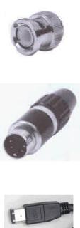
There are three types of plugs used for video signals on the SE-800: BNC, S-video, and DV.
BNC connectors look like this on the cable end. The connector slides over the connector on the SE-800 and is locked in place with a push in and clockwise turn. The big virtue of these connectors, which are the standard for almost all professional video applications, is that they lock in place and cannot be accidentally dislodged.
S-video plugs (also known as Y/C) have 4 tiny pins in them, which carry a separated Y (luminance) and C (chroma) video signal and provide a much better quality video signal than composite. These plugs have a tiny bar in them to assure correct alignment in the socket. They need to be pressed firmly in place, but very carefully, as the little pins can bend easily. Align plug and socket and push straight in, firmly.
DV plugs come in 4 pin and 6 pin connector sizes. The SE-800 uses the 6-pin variety. The 6-pin size is typically found on computer interfaces, hard drives, CD burners, etc. You’ll notice that one side of the plug is indented. This fits into the socket on the SE-800 one way, and one way only. It is a tight fit, for security and stability, so push straight and firmly, but
don’t force it without first making sure it is correctly oriented. If you need to run a DV cable longer than 20 meters (roughly 65 feet), you must use a DV repeater, such as Datavideo’s VP-332 or VP-314 (page 62), to avoid signal loss caused by the distance. You can also use Datavideo’s DV Repeater /DA (distribution amplifier) to have more than one DV output from the switcher. Add the DV Repeater/DA and you have five DV outs.
Connecting Audio Sources
The SE-800 uses 2 kinds of plugs for audio connections: RCA and 1/4 inch jack plugs. There are lots of different names for these plugs. Fortunately for us all, they are not easily confused in the size and shape departments, so we’ll show you some pictures.
12
RCA plugs (also sometimes known as phono plugs, cinch, or tulips) are used for line level audio, such as the connections between a CD player and amp. The SE-800 uses these in stereo pairs, white for left and red for right, at the audio input and output sections.
1/4 inch jack plugs got their name, some say, because they used to be used to manually patch together phone lines in the old central switchboard days. They come in mono and stereo configurations: the mono has one dark band around the plug, the stereo has two. The SE-800 uses mono plugs for microphone inputs and a stereo plug for headphones.
If you need to use balanced audio inputs or outputs, for low impedance microphones or connections with other professional audio gear, you need to use an impedance matching device to convert low to high impedance (and/or vice versa). For example Datavideo BAC-03 (on page 62)
Outputs and Monitors
Your particular set up and application for the SE-800 will determine what video and audio devices you connect to the outputs. Take a look at the Sample Applications, page 15 for some examples. While all the outputs of the SE-800 are very high quality, keep in mind that the video quality of the various formats, in descending order, goes like this: SDI (serial digital), Y.U.V. (analog component), DV, Y/C (S-video), and composite. Audio outputs are all line level, suitable for connecting to an amp, VCR, or video projector (for example).
We can’t stress enough the importance of good monitoring systems. If something doesn’t look or sound right at the last stage of the signal path, the Main output, it can only be easily corrected if you can pinpoint where in the signal path the problem is being introduced.
Certain set ups will benefit greatly by being able to monitor the video of each input channel, as well as the Main output. High quality headphones allow you to hear the audio with far fewer intermediate steps and far more accuracy, thanks to the Headphone controls on the front panel, than going through an amp and speakers. We suggest both methods of monitoring, and listening to the sound through a video monitor’s speakers is also a good idea. Needless to say, if you are outputting to a record deck, you should be able to easily monitor the output of that device as well.
Connecting a Datavideo TLM-404 4” x 4 TFT LCD for four input video channels monitoring, page 60.
13
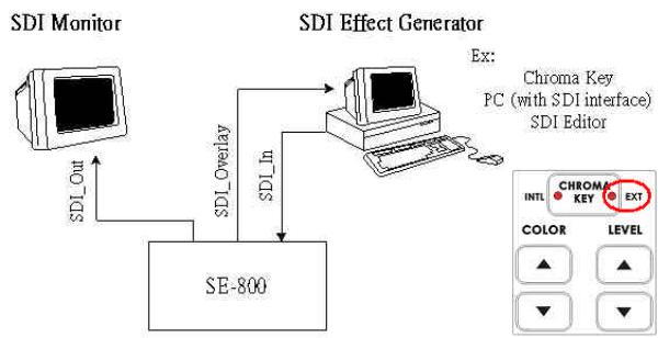
Using SE-800 SDI Overlay interface for CG Text overlay
Using SDI interface (270 Mbps, SMPTE 259M standard) and the EXT Chroma-Key effect on SE-800 to communicate with a PC SDI CG overlay card and perform a text overlay for the output video, page 45.
GPI Trigger
A GPI (General Purpose Interface) trigger is connected here by means of a mini plug (1/8”). This device allows you to make the SE-800 do certain things at the specific moment you press the trigger, such as making transitions and effects happen. For more information on what you can do with the GPI Trigger, see
Using Transitions, page 35, and Using Effects, page 41.
RS-232 control
•Connects a Datavideo SE-800 Remote Control Panel RMC-90, page 61.
•Connects to PC RS-232 serial interface for remote controlled by PC application software. Refer to the Appendix detail of RS-232 Remote Control Protocol, page 67.
14
Quick Start
We’ve made three sample application set ups for using the Switcher: Production studio; Multi-camera event (city council meeting, church service, etc); and Performance (club VJ, concert visuals, etc.). Pick the one that most closely approximates your initial intended use, follow the block diagram to make the video and audio connections, and jump in to using the controls. For more in-depth information on specific connections, controls, and functions, please see the appropriate section of this manual.
Sample Applications |
|
|
|
|
|
|
|
|
|
|
|
|
|
|
|
|
|
|
|
||||
|
|
|
|
|
|
|
|
|
|
|
|
|
|
Connect CD Player or |
|||||||||
|
|
|
|
|
|
|
|
|
|
|
|
|
|
|
|
|
|
|
|||||
|
|
|
|
|
|
|
|
|
|
|
|
|
|
|
|
|
|
|
other tape player, for |
||||
|
|
|
|
|
|
|
|
|
|
Connect Studio Mixer, VCR |
|||||||||||||
|
|
|
|
|
|
|
|
|
|
|
background music |
||||||||||||
|
|
|
|
|
|
|
|
|
|
|
|
|
|
|
|
|
|
|
|||||
|
|
|
|
|
|
|
|
|
|
|
|
|
|
|
|
|
|
|
|
|
|
|
|
|
Studio Camera on |
|
|
|
|
|
|
|
|
|
|
|
|
|
|
|
|
|
|
|
|||
|
weather talent with |
|
|
|
Studio Camera |
|
|
|
|
|
|
|
|
|
|
Weather talent |
|||||||
|
green/blue screen |
|
|
|
on Anchor |
|
|
|
|
|
|
|
|
|
|
||||||||
|
|
|
|
|
|
|
|
|
|
|
|
|
|
mic, Anchor mic |
|||||||||
|
|
|
|
|
|
|
|
|
|
|
|
|
|
|
|
|
|
|
|
|
|
|
|
|
|
|
|
|
|
|
|
|
|
|
|
|
|
|
|
|
|
|
|
|
|
|
|
|
|
|
|
|
|
|
|
|
|
|
|
|
|
|
|
|
|
|
|
|
|
|
|
|
|
|
|
|
|
|
|
|
|
|
|
|
|
|
|
|
|
|
|
|
|
|
|
|
|
|
|
|
|
|
|
|
|
|
|
|
|
|
|
|
|
|
|
|
|
|
|
|
|
|
|
|
|
|
|
|
|
|
|
|
|
|
|
|
|
|
|
|
|
|
|
|
|
|
|
|
|
|
|
|
|
|
|
|
|
|
|
|
|
|
|
|
|
|
|
|
|
|
|
|
|
|
|
|
|
|
|
|
|
|
|
|
|
|
|
|
|
|
|
|
|
|
|
|
|
|
|
|
|
|
|
|
|
|
|
|
|
|
|
|
|
|
|
|
|
|
|
|
|
|
|
|
|
|
|
|
|
|
|
|
|
|
|
|
|
|
|
|
|
|
|
|
|
|
|
|
|
|
|
|
|
|
|
|
|
|
|
|
|
|
|
|
|
|
|
|
|
|
|
|
|
|
|
|
|
|
|
|
|
|
|
|
|
|
|
|
|
|
|
|
|
|
|
|
|
|
|
|
|
|
|
|
|
|
|
|
|
|
|
|
|
|
|
|
|
|
|
|
|
|
|
|
|
|
|
|
|
|
|
|
|
|
|
Video Pass thru to a preview monitor or Datavideo TLM-404 4”x4 TFT LCD Display
Connect DV input sources, such as Datavideo DV Bank for background video
To Master |
|
|
|
Connect a program |
|
Recorder Deck |
|
|
|
Monitor |
|
|
|
|
|
|
|
|
|
|
Production studio: cable weather/news show
Text on diagram: This is but one of a nearly infinite number of possible production studio set-ups. It shows mixing a live green/blue screen camera with background footage, such as in a weather segment of a news show, and recording the result to a master recorder.
Do this:
Connect the recorder, input, and monitor devices as shown.
Turn on all peripherals, then power up the SE-800. You can tell that the initialization cycle has completed when the Main Video Source LEDs (4.) and others are lit.
Jump to the next sections to finish set up procedures and then explore the other basic functions described below.
15
|
|
DV Camera 2 |
DV Camera 4 |
|
|
|
|
||||
Connect CD Player or other tape |
|||||||||||
DV Camera 1 |
|
|
|
|
|||||||
|
DV Camera 3 |
player, for background music |
|||||||||
|
|||||||||||
|
|
|
|
||||||||
|
|
|
|
|
|
|
|
|
|
|
|
|
|
|
|
|
|
|
|
|
|
|
|
|
|
|
|
|
|
|
|
|
|
|
|
|
|
|
|
|
|
|
|
|
|
|
|
|
|
|
|
|
|
|
|
|
|
|
|
|
|
|
|
|
|
|
|
|
|
|
|
|
|
|
|
|
|
|
|
|
|
|
|
|
|
|
|
|
|
|
|
|
|
|
|
Preview |
Preview |
|
|
|
Moderator mic |
|
Monitor 1 |
Monitor 3 |
|
|
|
Council mic |
|
To DV |
||||||
|
|
|
|
Audience mic |
||
|
|
Recorder Deck |
|
|
||
Preview |
Preview |
|
|
|
||
|
|
|
||||
|
|
|
|
|||
|
|
From Audio Mixer, VCR… |
||||
Monitor 2 |
Monitor 4 |
|
|
|||
|
|
|
|
|||
Multi-camera event: city council meeting
Text on diagram: This multi-camera event could just as easily be a church service, Queen for a Day pageant, school play, or jazz concert; the general idea of the set up remains the same. It assumes multiple live camera feeds, analog and digital and multiple audio sources being recorded to a master recorder, in this case a DV deck.
Do this:
Connect the recorder, input, and monitor devices as shown.
Turn on all peripherals, then power up the SE-800. You can tell that the initialization cycle has completed when the Main Video Source LEDs (4.) and others are lit.
Jump to the next sections to finish set up procedures, and then explore the other basic functions described below.
16
DV Bank 2 |
DV Camera on |
|
dance floor4 |
||
|
DV Bank 1
DVD Player
Preview |
Preview |
Monitor 1 |
Monitor 3 |
Preview |
Preview |
Monitor 2 |
Monitor 4 |
Connect CD Player for background music
From Club |
|
Moderator mic |
Audio Mixer. |
|
Audience mic |
|
|
|
To club video system
To VTR recorder and program monitor
Live Performance Mix: Dance club VJ
Text on diagram: This diagram shows one of many possible club VJ set ups, but could be adapted to any performance event, such as a lecture/demonstration, mixed media performance, or even live music video production; it assumes multiple audio and video inputs, an audience viewing monitor, and simultaneous recording of the mix.
Do this:
Connect the recorder, input, and monitor devices as shown.
Turn on all peripherals, then power up the SE-800. You can tell that the initialization cycle has completed when the Main Video Source LEDs (4.) and others are lit.
Jump to the next sections to finish set up procedures, and then explore the other basic functions described below.
17

3 |
4 |
5 |
6 |
7 |
8 |
1 
2 
24 |
9 |
|
10 |
||
23 |
||
|
||
22 |
11 |
|
|
||
21 |
|
|
20 |
19 |
18 |
16 |
17 |
15 |
14 |
12 |
|
|
|
|
13 |
||||
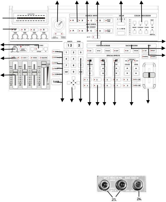
1. |
Audio meters |
|
|
19. |
Cursor Keys |
|
||
2. |
Audio input selectors and level controls |
|
20. |
Transition mode selectors |
||||
3. |
Joy stick and mode selector |
|
|
21. |
Audio faders |
|
||
4. |
Main Video source selector |
|
|
22. Audio Input channel selectors |
||||
5. |
Sub video source selector |
|
|
23. |
Headphone level control |
|||
6. |
Audio follow video switch |
|
|
24. |
Voice sync adjustment |
|||
7. |
Input format selector |
|
|
25. |
Microphone input Left/Right |
|||
8. |
Color processor |
|
|
26. |
Headphone jack |
|
||
9.Border control
10.Background control
11.Mode selectors
12.T-Bar
13.Chroma key control
14.Special effects: Picture in Picture
15.Special effects: Paint controls
16.Special effects: Mosaic controls
17.Preset Banks F1 to F30
18.Numeric Keypad
18
Selecting video input formats and adjusting audio levels
(Numbers refer to the Front Panel illustration above)
*. Verify that there is a valid source at each input you’ve connected by using the Main Source Select buttons (4.) to select a channel and view the output on the main monitor.
For each input channel (A, B, C, D): press the top Input Format button (7.) to select the channel, then press the bottom button to select the proper video format. DV = digital video through FireWire (a.k.a. iLink or IEEE 1394); V = composite video; S = S-video; YUV = component video.
For each input channel, use the Audio Input Selectors (22.) to engage a channel; set the level using the rotary pot below the channel button so that the LEDs in the Audio Meters (1.) peak occasionally to +6 or +9 and there is no audible distortion. Make sure the A+V button (6.) is not lit so you can monitor and adjust audio from channels that aren’t selected on the Main Source bus. Adjust any other audio input levels you will be using, for example microphones, Aux in from a mixer, etc.
Use the Audio Channel Selector buttons (22.) and Faders (21.) to set the audio output levels so that there is no audible distortion and they peak occasionally to +3 or +6.
Using Video and Audio Monitors
We’ll save the speech on how important monitoring is for another section. Suffice it to say that without reliable video and audio monitors, you won’t be able to tell what’s what in your mix.
The SE-800 provides the ability to easily and reliably monitor video and audio at both the input and output stages.
Each input channel video can be monitored by connecting to the channel’s Monitor Output, with either one monitor per channel as in example set ups 2 and 3 above (page 16, 17), or to a passive switch box as in example set up 1, page 15.
You should have a video monitor displaying the Main Output. This could be a composite monitor, for example, connected to the V plug (Composite) in the Video Output section (11c, page10), or to the composite output of a VCR connected to the Video Output, or even, by using Datavideo DV Repeater to provide multiple parallel DV outputs, a DV recorder and monitor.
Input audio can be monitored at the Headphone jack (26.), using the Headphone controls (23.) to set the level and the button to cycle through input busses. With the input bus set to Video (VCR), use the Audio Input selectors (2.) to audition individual sources.
For output audio monitoring with headphones, set the Headphone selector to MASTER; to monitor through an amplifier and speakers, make sure the MASTER button is lit in the Audio Faders (21.) section.
For more information, see Controls and Operations, page 22.
19
Cutting between sources
The simplest way to cut (switch) between source video inputs: use the Video Main Source buttons (4.) to select which input goes to the program monitor (output). Look at the results on your program or record monitor.
Dissolving between sources
Select the Main Video Source (4.) by pressing the appropriate channel button. The LED for the channel you have selected should be lit and you should see that source on the program monitor.
Select the Sub Video Source (5.) you want to dissolve to.
Make sure the Mode Selector (11.) is on Video (the LED on the button will be lit).
With nothing selected in the Transitions (20.) controls (no LEDs lit on any of the buttons means none are selected. If one is selected at power up, press it to deselect.), the default transition is dissolve. Move the T-Bar (12.) to the opposite position and watch the dissolve happen on the program monitor. You can stop the dissolve part way through and watch a mix of the sources.
Or:
Select the Fade transition button (20.) by pressing it until it is lit. Set the speed for the transition using the SPD key on the Keypad (18.) to change the read out in the Speed window, on the right above the Keypad (1 is slowest, 9 is fastest). Hit the Take-button (20.) and watch the transition automatically happen. If you want to switch automatically between the audio channels associated with each source, make sure the A+V button (6.) is lit. You should see the resulting transition on your program monitor.
Other transitions between sources
Select Main and Sub sources as above.
Press the Wipe key (20.) so it is lit. Use the Keypad (18.) to select the wipe you wish to use. Wipe styles are numbered from 01 to 24 and displayed in the left window above the Keypad.
At this point you can either use the T-Bar to perform the wipe manually or set the speed on the keypad as above and use the Take-button to do auto-wipe.
For more information, see Using Transitions, page 35.
Effects
There are two places on the SE-800 where you can add effects: in the Special Effects section (1416.) and in the Auto plays section (20.). Some of these work on a single source, and some need two sources to work. Select a Main Video source and try the following:
In the Auto play section; select Freeze to grab a still frame of the Main Source video. Hit the Take button to cut to the Sub Video Source or move the T-Bar to manually dissolve to the Sub Video Source.
Again, in the Auto play section, press the MISC button à01 buttons à and then Take button to apply a strobe effect (automatic successive freeze frames) to the selected Main Source Video. Choose a speed from the Keypad (18.): 1 is fastest (more freeze frames per second) and 4 is slowest. Press the MISC button à02 buttons à and then Take button to apply a black and white video effect
In the Special Effects section, press the Mosaic (16.) button so that the LED on the button is lit. As you can see, this pixilated the video, or turns it into blocky chunks. Select the size of the pixel blocks by
20
pressing the up and down arrow keys; sizes are numbered 1-8 and displayed in the Effects window above the Keypad. Alternately, you can enter numbers 1-8 on the Keypad. There are 3 options for how much of the image is affected; PIP/Mosaic effect can be selected by pressing the PIP button in Mosaic mode, press the PIP “Up”, “Down” arrow keys for Mosaic/PIP picture size which can be positioned using the Joystick (3.). Press the Joystick Mode Selector button, below the Joystick, so that the Position Control LED is lit. Have fun positioning the Mosaic-ed window anywhere you want.
Next, try the Paint effect (15.). Press the button to engage the effect, and the LED lights. There are 4 levels of intensity to this effect, with 1 being the least intense and 4 the most effected. You can enter the numbers 1-4 on the Keypad or press the up and down arrows beneath the Paint effect button to change levels. The level number is displayed in the Effects window above the Keypad.
PIP effect (14.), which stands for Picture in Picture. As you might guess, this effect requires a Main and Sub Video Source. Assuming you have valid inputs on Channel A and B, select Channel A as the Main Source and Channel B as the Sub Source. When you engage the effect by pressing the PIP button (and verifying that the LED on the button is lit), you will have Channel A as the Main Source (you are, of course, watching a program monitor!) and Channel B as a smaller window inset. There are two choices for window size (1 is largest), displayed in the Speed window above the Keypad. Change these by pressing the up and down arrow keys beneath the Effect selection button. You can position this window using the Joystick (3.), with the button set to Position Control (LED is lit). Experiment with different window borders by first turning on the Border control (9.), then trying different sizes, colors, and softness levels.
For more information, see Using Effects, page 41
This concludes our Quick Start section. By now, you should have a good idea of some of the capabilities of your new SE-800 Digital Video Switcher!
21
Controls and Operations
SE-800 Front Panel
3 |
4 |
5 |
6 |
7 |
8 |
1 
2 
24 |
9 |
|
10 |
||
23 |
||
|
||
22 |
11 |
|
|
||
21 |
|
|
20 |
19 |
18 |
17 |
15 |
14 |
13 |
12 |
|
|
|
|
16 |
|
|||||
1. |
Audio meters |
|
|
19. |
Cursor Keys |
|
|
||
2. |
Audio input selectors and level controls |
|
20. |
Transition mode selectors |
|
||||
3. |
Joy stick and mode selector |
|
|
21. |
Audio faders |
|
|
||
4. |
Main Video source selector |
|
|
22. |
Audio channel selectors |
|
|||
5. |
Sub video source selector |
|
|
23. |
Headphone |
|
|
||
6. |
Audio follow video switch |
|
|
24. |
Voice sync adjustment |
|
|||
7. |
Input format selector (Setup video) |
|
|
25. |
Microphone input Left/Right |
||||
8. |
Color processor |
|
|
26. |
Headphone jack |
|
|
||
9.Border control
10.Background control
11.Mode selectors
12.T-Bar
13.Chroma key control
14.Special effects: Picture in Picture
15.Special effects: Paint controls
16.Special effects: Mosaic controls
17.Preset Banks F1 to F30
18.Numeric Keypad
22
 Loading...