


HD 4-CHANNEL DIGITAL
VIDEO SWITCHER
SE-650
Instruction Manual
|
|
Table of Contents |
|
FCC COMPLIANCE STATEMENT........................................................................................................... |
5 |
||
WARNINGS AND PRECAUTIONS ......................................................................................................... |
5 |
||
WARRANTY........................................................................................................................................ |
6 |
||
STANDARD WARRANTY................................................................................................................................. |
6 |
||
THREE YEAR WARRANTY ............................................................................................................................... |
6 |
||
DISPOSAL ........................................................................................................................................... |
|
7 |
|
CHAPTER .............................................................................................................1 |
INTRODUCTION |
8 |
|
1.1 |
F .......................................................................................................................................EATURES |
8 |
|
1.2 |
S ............................................................................................................................YSTEM DIAGRAM |
9 |
|
CHAPTER ...................................................................................2 CONNECTIONS AND CONTROLS |
10 |
||
2.1 |
R ..................................................................................................................................EAR PANEL |
10 |
|
2.2 |
F ................................................................................................................................RONT PANEL |
12 |
|
CHAPTER ........................................................................................................3 |
NETWORK SETUP |
18 |
|
3.1 |
S ..................................................................................WITCHER SETUP WITH A WINDOWS COMPUTER |
18 |
|
3.2 |
I ........................NSTALLING THE SWITCHER IMAGE IMPORT/EXPORT SOFTWARE TO A WINDOWS COMPUTER |
19 |
|
3.2.1 ...................................................................................................... |
Router Based DHCP Setup |
20 |
|
3.2.2 ................. |
Setting the Target IP Address with the Switcher Image Import/Export Software |
21 |
|
CHAPTER ..................................................................................................................4 |
OSD MENU |
23 |
|
4.1 |
S ..........................................................................................................................................TART |
23 |
|
4.1.1 ............................................................................................................................... |
Transition |
23 |
|
4.1.2 ....................................................................................................................................... |
Type |
23 |
|
4.1.3 ........................................................................................................................... |
Wipe Effects |
23 |
|
4.1.4 .................................................................................................................................... |
Border |
23 |
|
4.1.5 .................................................................................................................................. |
Position |
24 |
|
4.1.6 ..................................................................................................................................... |
Matte |
24 |
|
4.2 |
K ..........................................................................................................................................EYER |
24 |
|
4.2.1 ...................................................................................................................................... |
Keyer |
24 |
|
4.2.2 ......................................................................................................................... |
Keyer Control |
24 |
|
4.2.3 .............................................................................................................................. |
Key Source |
25 |
|
4.2.4 ............................................................................................................................... |
Fill Source |
25 |
|
4.2.5 ................................................................................................................................. |
CK Setup |
25 |
|
4.2.6 ...................................................................................................................................... |
Mask |
26 |
|
4.3 |
P .........................................................................................................................................-IN-P |
26 |
|
4.3.1 .......................................................................................................................... |
P-In-P Source |
26 |
|
4.3.1 .................................................................................................................................. |
Position |
26 |
|
4.3.2 .................................................................................................................................... |
Border |
27 |
|
4.3.3 ........................................................................................................................................ |
Crop |
27 |
|
|
|
2 |
|
4.4 |
P-IN-P KEYER ................................................................................................................................ |
27 |
|
4.4.1 |
P-In-P Source.......................................................................................................................... |
27 |
|
4.4.2 |
Keyer ...................................................................................................................................... |
28 |
|
4.4.3 |
Keyer Control ......................................................................................................................... |
28 |
|
4.4.4 |
CK Setup................................................................................................................................. |
28 |
|
4.4.5 |
Mask ...................................................................................................................................... |
28 |
|
4.5 |
LOGO ........................................................................................................................................... |
29 |
|
4.5.1 |
Logo Image ............................................................................................................................ |
29 |
|
4.5.2 |
Logo Control........................................................................................................................... |
29 |
|
4.5.3 Logo Source (Logo Src)........................................................................................................... |
29 |
||
4.5.4 |
Fill Source............................................................................................................................... |
30 |
|
4.5.5 |
Mask ...................................................................................................................................... |
30 |
|
4.5.6 |
Logo Insertion ........................................................................................................................ |
30 |
|
4.6 |
STILLS........................................................................................................................................... |
31 |
|
4.6.1 |
Load Still................................................................................................................................. |
31 |
|
4.6.2 |
Save Still................................................................................................................................. |
32 |
|
4.6.3 |
Grab Still ................................................................................................................................ |
32 |
|
4.6.4 |
Freeze..................................................................................................................................... |
32 |
|
4.6.5 Export/Import Still Images to/from the PC............................................................................ |
32 |
||
4.6.6 |
Loading still images ............................................................................................................... |
38 |
|
4.7 |
USER MEMS.................................................................................................................................. |
39 |
|
4.7.1 |
Load Memory......................................................................................................................... |
39 |
|
4.7.2 |
Save Memory ......................................................................................................................... |
39 |
|
4.7.3 |
Load Clip ................................................................................................................................ |
39 |
|
4.7.4 Loading the existing Clip for Stinger Transition Effect .......................................................... |
40 |
||
4.7.5 Importing the Clip for Stinger Transition Effect from the PC................................................. |
40 |
||
4.7.6 How to Create the PNG Sequence for Stinger Transition Effect ............................................ |
42 |
||
4.7.7 Important things to note while creating Stinger Transition Effects ...................................... |
48 |
||
4.8 |
INPUTS ......................................................................................................................................... |
49 |
|
4.8.1 |
Input 1-4 ................................................................................................................................ |
49 |
|
4.8.2 |
Freeze..................................................................................................................................... |
49 |
|
4.8.3 |
Crosspoint .............................................................................................................................. |
49 |
|
4.9 |
OUTPUTS ...................................................................................................................................... |
50 |
|
4.9.1 |
Outputs .................................................................................................................................. |
50 |
|
4.9.2 |
Audio...................................................................................................................................... |
50 |
|
4.9.3 |
Tally Mode ............................................................................................................................. |
51 |
|
4.9.4 |
Multiviewer............................................................................................................................ |
51 |
|
4.10 |
SETUP .......................................................................................................................................... |
51 |
|
4.10.1 |
Standard............................................................................................................................ |
52 |
|
4.10.2 |
Menu Mode....................................................................................................................... |
52 |
|
4.10.3 |
Menu Preference............................................................................................................... |
52 |
|
4.10.4 |
Auto Save .......................................................................................................................... |
52 |
|
4.10.5 |
Factory Default.................................................................................................................. |
52 |
|
|
|
3 |
|
4.10.6 |
Reset Names...................................................................................................................... |
52 |
|
4.10.7 |
Language........................................................................................................................... |
52 |
|
4.10.8 |
Software ............................................................................................................................ |
52 |
|
CHAPTER 5 |
APPLICATIONS............................................................................................................. |
53 |
|
5.1 |
CHROMAKEYER .............................................................................................................................. |
53 |
|
5.2 |
LOGO INSERTION ............................................................................................................................ |
53 |
|
5.3 |
STILL IMAGES................................................................................................................................. |
54 |
|
5.3.1 Export/Import Still Images to/from the PC............................................................................ |
54 |
||
5.3.2 Loading still images ............................................................................................................... |
60 |
||
5.4 |
STINGER TRANSITION EFFECT ............................................................................................................ |
61 |
|
5.4.1 Loading the existing Clip for Stinger Transition Effect .......................................................... |
61 |
||
5.4.2 Importing the Clip for Stinger Transition Effect from the PC................................................. |
62 |
||
5.4.3 How to Create the PNG Sequence for Stinger Transition Effect ............................................ |
64 |
||
5.4.4 Important things to note while creating Stinger Transition Effects ...................................... |
69 |
||
5.5 |
USER MEMORY.............................................................................................................................. |
70 |
|
5.5.1 Export/Import User Memory Preset to/from the PC ............................................................. |
70 |
||
5.5.2 Loading User Memory Preset ................................................................................................ |
72 |
||
CHAPTER 6 |
APPENDICES ................................................................................................................ |
73 |
|
APPENDIX 1 |
TALLY OUTPUTS ...................................................................................................................... |
73 |
|
APPENDIX 2 |
FIRMWARE UPGRADE............................................................................................................... |
74 |
|
APPENDIX 3 |
FREQUENTLY-ASKED QUESTIONS................................................................................................ |
75 |
|
APPENDIX 4 |
DIMENSIONS .......................................................................................................................... |
76 |
|
APPENDIX 5 |
SPECIFICATIONS ...................................................................................................................... |
77 |
|
SERVICE AND SUPPORT.................................................................................................................... |
80 |
||
Disclaimer of Product & Services
The information offered in this instruction manual is intended as a guide only. At all times, Datavideo Technologies will try to give correct, complete and suitable information. However, Datavideo Technologies cannot exclude that some information in this manual, from time to time, may not be correct or may be incomplete. This manual may contain typing errors, omissions or incorrect information. Datavideo Technologies always recommend that you double check the information in this document for accuracy before making any purchase decision or using the product. Datavideo Technologies is not responsible for any omissions or errors, or for any subsequent loss or damage caused by using the information contained within this manual. Further advice on the content of this manual or on the product can be obtained by contacting your local Datavideo Office or dealer.
4

FCC Compliance Statement
This device complies with part 15 of the FCC rules. Operation is subject to the following two conditions:
(1)This device may not cause harmful interference, and
(2)This device must accept any interference received, including interference that may cause undesired operation.
Warnings and Precautions
1.Read all of these warnings and save them for later reference.
2.Follow all warnings and instructions marked on this unit.
3.Unplug this unit from the wall outlet before cleaning. Do not use liquid or aerosol cleaners. Use a damp cloth for cleaning.
4.Do not use this unit in or near water.
5.Do not place this unit on an unstable cart, stand, or table. The unit may fall, causing serious damage.
6.Slots and openings on the cabinet top, back, and bottom are provided for ventilation. To ensure safe and reliable operation of this unit, and to protect it from overheating, do not block or cover these openings. Do not place this unit on a bed, sofa, rug, or similar surface, as the ventilation openings on the bottom of the cabinet will be blocked. This unit should never be placed near or over a heat register or radiator. This unit should not be placed in a built-in installation unless proper ventilation is provided.
7.This product should only be operated from the type of power source indicated on the marking label of the AC adapter. If you are not sure of the type of power available, consult your Datavideo dealer or your local power company.
8.Do not allow anything to rest on the power cord. Do not locate this unit where the power cord will be walked on, rolled over, or otherwise stressed.
9.If an extension cord must be used with this unit, make sure that the total of the ampere ratings on the products plugged into the extension cord do not exceed the extension cord rating.
10.Make sure that the total amperes of all the units that are plugged into a single wall outlet do not exceed 15 amperes.
11.Never push objects of any kind into this unit through the cabinet ventilation slots, as they may touch dangerous voltage points or short out parts that could result in risk of fire or electric shock. Never spill liquid of any kind onto or into this unit.
12.Except as specifically explained elsewhere in this manual, do not attempt to service this product yourself. Opening or removing covers that are marked “Do Not Remove” may expose you to dangerous voltage points or other risks, and will void your warranty. Refer all service issues to qualified service personnel.
13.Unplug this product from the wall outlet and refer to qualified service personnel under the following conditions:
a.When the power cord is damaged or frayed;
b.When liquid has spilled into the unit;
c.When the product has been exposed to rain or water;
d.When the product does not operate normally under normal operating conditions. Adjust only those controls that are covered by the operating instructions in this manual; improper adjustment of other controls may result in damage to the unit and may often require extensive work by a qualified technician to restore the unit to normal operation;
e.When the product has been dropped or the cabinet has been damaged;
f.When the product exhibits a distinct change in performance, indicating a need for service.
5

Warranty
Standard Warranty
•Datavideo equipment are guaranteed against any manufacturing defects for one year from the date of purchase.
•The original purchase invoice or other documentary evidence should be supplied at the time of any request for repair under warranty.
•The product warranty period begins on the purchase date. If the purchase date is unknown, the product warranty period begins on the thirtieth day after shipment from a Datavideo office.
•All non-Datavideo manufactured products (product without Datavideo logo) have only one year warranty from the date of purchase.
•Damage caused by accident, misuse, unauthorized repairs, sand, grit or water is not covered under warranty.
•Viruses and malware infections on the computer systems are not covered under warranty.
•Any errors that are caused by unauthorized third-party software installations, which are not required by our computer systems, are not covered under warranty.
•All mail or transportation costs including insurance are at the expense of the owner.
•All other claims of any nature are not covered.
•All accessories including headphones, cables, and batteries are not covered under warranty.
•Warranty only valid in the country or region of purchase.
•Your statutory rights are not affected.
Three Year Warranty
•All Datavideo products purchased after July 1st, 2017 are qualified for a free two years extension to the standard warranty, providing the product is registered with Datavideo within 30 days of purchase.
•Certain parts with limited lifetime expectancy such as LCD panels, DVD
drives, Hard Drive, Solid State Drive, SD Card, USB Thumb Drive, Lighting, Camera module, PCIe Card are covered for 1 year.
•The three-year warranty must be registered on Datavideo's official website or with your local Datavideo office or one of its authorized distributors within 30 days of purchase.
6

Disposal
For EU Customers only - WEEE Marking
This symbol on the product or on its packaging indicates that this product must not be disposed of with your other household waste. Instead, it is your responsibility to dispose of your waste equipment by handing it over to a designated collection point for the recycling of waste electrical and electronic equipment. The separate collection and recycling of your waste equipment at the time of disposal will help to conserve natural resources and ensure that it is recycled in a manner that protects human health and the environment. For
more information about where you can drop off your waste equipment for recycling, please contact your local city office, your household waste disposal service or the shop where you purchased the product.
CE Marking is the symbol as shown on the left of this page. The letters "CE" are the abbreviation of French phrase "Conformité Européene" which literally means "European Conformity". The term initially used was "EC Mark" and it was officially replaced by "CE Marking" in the Directive 93/68/EEC in 1993. "CE Marking" is now used in all EU official documents.
7
Chapter 1 Introduction
The datavideo SE-650 is a small, cost-effective, HD digital video switcher with easy-to-use professional features. It offers two HD SDI and two HDMI inputs. Output options include one user assignable HD SDI, two HDMI outputs.
The SE-650 also features an audio mixer with microphone and unbalance RCA audio inputs; more features include Chroma Keyer, Luma Keyer, PIP, Wipe Generator, Still stores and Tally.
1.1 Features
•4 video Input : HD-SDI x 2 + HDMI x 2
-Frame Sync on each input
•3 Video Outputs : HD-SDI x 1 + HDMI x 2
•Audio input : Stereo RCA (L/R) x 1 + Microphone x 2
•Audio Output : Stereo RCA (L/R) x 1 + Stereo headphone mini Jack x 1
•Audio Mixer : MIC x 2 + Stereo x 1 + internal Digital embedded x 1
•Flexible Mix/Effects Processor with
-1 Upstream Keyer, supporting Chroma Key & Linear/Luma Key
-1 Upstream PIP, supporting Chroma Key & Luma Key Modes as well as unkeyed mode
-Wipe Generator
32 Wipe Patterns, including Circle & Heart
Borders & Softness Control
-Wipe, Mix & Cut Transitions
-Full M/E Preview function
-Logo insertion
•Any Input (1-4) can be used as a Frame store (Stills Store)
•Assignable Outputs
-Program (w/ DSK)
-Clean Program (w/o DSK)
-Clean Preview (w/o DSK)
-Multiview
-One of the input signals
•XPT (Cross Point Assignment)
•Tally Output
8
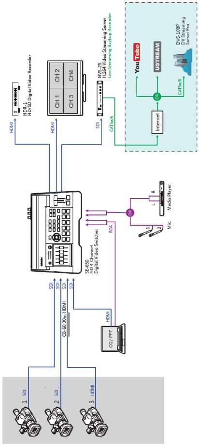
1.2 System Diagram
9
Chapter 2 Connections and Controls
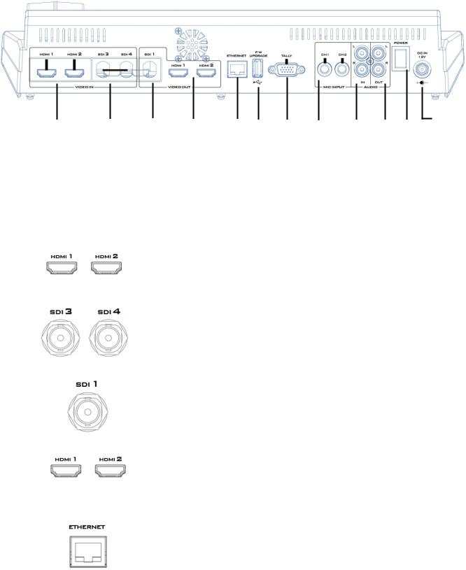
2.1 Rear Panel
1 |
2 |
3 |
4 |
5 |
6 |
7 |
8 |
9 |
10 |
12 |
11 |
1 |
HDMI Video Input 1-2 |
|
7 |
|
TALLY Output Port |
2 |
HD-SDI Video Input 3-4 |
|
8 |
MIC IN – CH1/CH2 |
|
3 |
HD-SDI Video Output 1 |
|
9 |
Audio Input – Stereo RCA (Left/Right) |
|
4 |
HDMI Video Output 1-2 |
|
10 |
Audio Output – Stereo RCA (Left/Right) |
|
5 |
Ethernet Port |
|
11 |
|
Power Switch |
6 |
USB F/W Upgrade Port |
|
12 |
|
DC IN |
|
|
|
|||
1 |
|
HDMI Video Input 1-2 |
|||
|
|
The SE-650 provides two HDMI video input channels for connecting |
|||
|
|
HDMI video sources. |
|
||
|
|
|
|||
2 |
|
HD-SDI Video Input 3-4 |
|||
|
|
The SE-650 provides two HD-SDI video input channels for connecting |
|||
|
|
HD-SDI video sources. |
|
||
|
|
|
|||
3 |
|
HD-SDI Video Output 1 |
|||
|
|
The SE-650 provides an HD-SDI video output channel which can be |
|||
|
|
connected to an HD-SDI video display. |
|||
|
|
|
|||
4 |
|
HDMI Video Output 1-2 |
|||
|
|
The SE-650 provides two HDMI video output channels which can be |
|||
|
|
connected to any HDMI video monitors. HDMI 1 is user assignable |
|||
|
|
and HDMI 2 outputs Multiview display. |
|||
|
|
|
|
||
5 |
|
Ethernet Port |
|
||
|
|
The Ethernet port allows the user to transfer files to and from the |
|||
|
|
switcher on the PC remotely. See Chapter 3 for details on how you |
|||
|
|
can utilize this port or perform system setup using this port. |
|||
|
|
Note: The SE-650 has a default IP address of 192.168.1.101. |
|||
|
|
|
|
|
|
|
|
10 |
|
|
|
6 |
|
|
USB F/W Upgrade Port |
|
|
|
|
|
|
USB port for firmware upgrade. Please refer to the Firmware |
|||
|
|
|
Upgrade section for the procedure. |
|||
|
|
|
|
|
|
|
7 |
|
|
TALLY Output Port |
|
|
|
|
|
|
Sends Red, and Green tally signals to each channel. |
|||
|
|
|
Red indicates On-Air, and Green indicates next camera source. Tally |
|||
|
|
|
output port can connect other Datavideo peripheral devices such as |
|||
|
|
|
ITC-100, ITC-200, AM-100 or other monitor models, allowing the |
|||
|
|
|
peripheral device to communicate with the SE-650 or send tally |
|||
|
|
|
signal to be displayed on the monitor. |
|||
|
|
|
|
|
|
|
8 |
|
|
MIC IN – CH1/CH2 |
|
|
|
|
|
|
Two Channels of unbalanced MIC input. |
|||
|
|
|
Left |
Right |
States |
|
|
|
|
Channel |
Channel |
|
|
|
|
|
MIC1 |
MIC2 |
MIC 1(L) and MIC 2(R) are respectively |
|
|
|
|
|
|
connected to left and right channels. |
|
|
|
|
MIC1 |
Not |
When MIC 1 is connected to the left |
|
|
|
|
|
Connected |
channel and MIC 2 is not connected to |
|
|
|
|
|
|
the right channel, the right channel |
|
|
|
|
|
|
switch will replicate MIC 1 signal onto |
|
|
|
|
|
|
the right channel thus both channels are |
|
|
|
|
|
|
MIC 1 input signals. |
|
|
|
|
Not |
MIC2 |
When no MIC signal is connected to the |
|
|
|
|
Connected |
|
left channel and only MIC 2 is connected |
|
|
|
|
|
|
to the right channel, MIC 2 signal will |
|
|
|
|
|
|
not be replicated onto the left channel |
|
|
|
|
|
|
which will thus be grounded. |
|
|
|
|
Not |
Not |
When no MIC is connected to the two |
|
|
|
|
Connected |
Connected |
channels, the left channel switch will |
|
|
|
|
|
|
ground the left channel to prevent noise |
|
|
|
|
|
|
from being generated. |
|
|
|
|
|
|||
9 |
|
|
Audio Input – Stereo RCA (Left/Right) |
|||
|
|
|
Connects unbalanced analog audio source (stereo) for streaming and |
|||
|
|
|
recording. |
|
|
|
|
|
|
|
|||
10 |
|
|
Audio Output – Stereo RCA (Left/Right) |
|||
|
|
|
Unbalanced analog audio output (stereo) for monitoring the |
|||
|
|
|
selected audio input source. |
|||
|
|
|
|
|
|
|
|
|
|
|
11 |
|
|
11 |
Power Switch |
|
Power switch ON/OFF |
12 |
DC IN |
|
DC in socket connects the supplied 12V / 19W PSU. The connection |
|
can be secured by screwing the outer fastening ring of the DC In plug |
|
to the socket. |
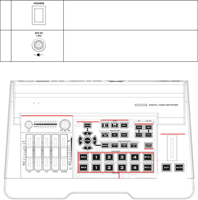
2.2 Front Panel
Volume Control |
|
|
|
|
|
|
|
|
|
|
|
|
|
|
|
|
|
|
|
|
Switcher |
|
Transition |
|
|
|
|
|
|
|
|
|
|||||
|
|
|
|
|
|
|
|
PIP/Keyer |
|
|||||||||
|
|
|
|
Settings |
|
Effects |
|
|
|
|
||||||||
|
|
|
|
|
|
|
|
|
|
|
|
|
|
|
|
|
|
|
|
|
|
|
|
|
|
|
|
|
|
|
|
|
|
|
|
|
|
|
|
|
|
|
|
|
|
|
|
|
|
|
|
|
|
|
|
|
|
|
|
|
|
|
|
|
|
|
|
|
|
|
|
|
|
|
|
|
|
|
|
|
|
|
|
|
|
|
|
|
|
|
|
|
|
|
|
|
|
|
|
|
|
|
|
|
|
|
|
|
|
|
|
|
|
|
|
|
|
|
|
|
|
|
|
|
|
|
|
|
|
|
|
|
|
|
|
|
|
|
|
|
|
|
|
|
|
|
|
|
|
|
|
|
|
|
|
|
|
|
|
|
|
|
|
|
|
|
|
|
|
|
|
|
|
|
|
|
|
|
|
|
|
|
|
|
|
|
|
|
|
|
|
|
|
|
|
|
|
|
|
|
|
|
|
|
|
|
|
|
Transition
Program/Preview
Switcher Settings |
|
Transition Methods |
Menu browsing buttons |
|
T-Bar (manual transition) |
RESET button |
|
CUT button |
User Memory |
|
AUTO transition button |
Transition Effects |
|
Program / Preview Outputs |
WIPE transition effect selection |
|
Program row |
TRANS BG – Background transition |
|
Preview row |
MIX Enable/Disable button |
|
Volume Control |
WIPE transition effect Enable/Disable |
|
Volume adjustment sliders |
|
|
Headphone jack |
PIP/Keyer |
|
|
PIP Enable/Disable buttons |
|
Audio meter |
Keyer Enable/Disable buttons |
|
Headphone volume control knob |
Logo Enable/Disable button |
|
|
|
12 |
|
Switcher Keyboard Descriptions
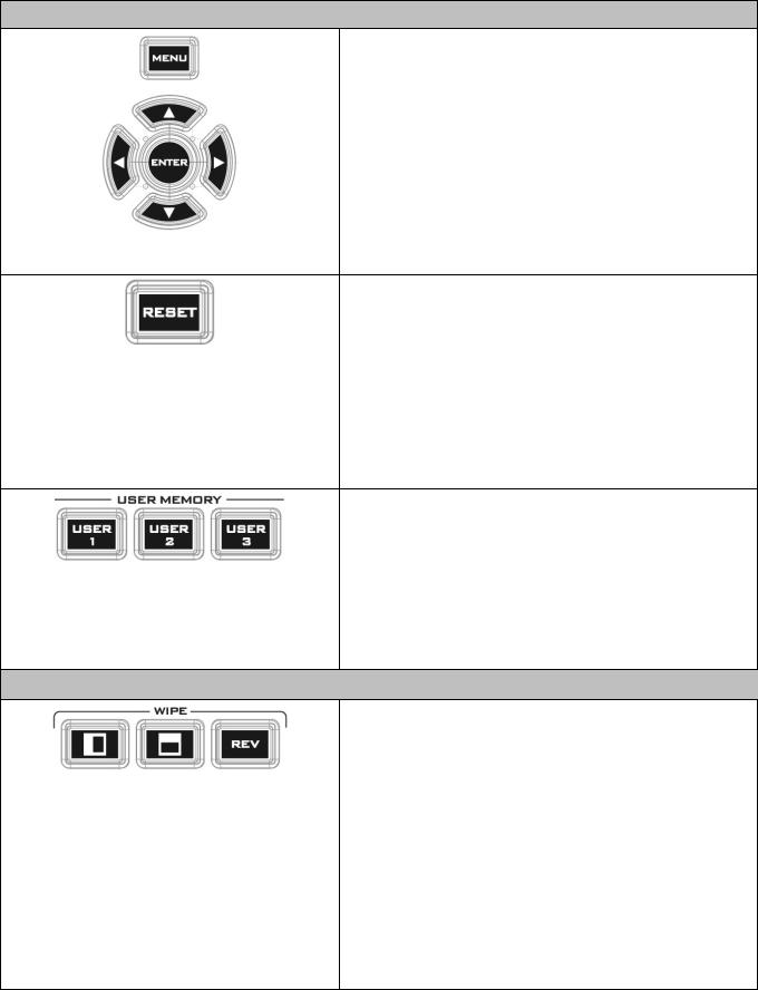
Menu browsing buttons
Press the MENU button to gain access to the menu; use the up/down/left/right arrow buttons to browse through the menu and press ENTER button to select an option or MENU button again to exit.
Reset Button
Mode 1 - When in Menu Select mode (left hand column of the OSD menu), pressing the 'Reset' button will reset all current menu items to their factory defaults.
Mode 2 - When in a Sub-Menu, pressing the 'Reset' button will reset the current menu line only.
User Memory
User Memory buttons 1-3 allow the user to quickly recall and load previously saved switcher settings with a single button press. This includes PIP, Keyer and DSK settings. The switcher loads settings saved to User Memory 0 as default settings used at boot up. See the User Memory section for more information.
Transition Effects
WIPE Transition Effect Selection
Each Wipe button consists of black and white colors. The white represents the current Program image and the black represents the WIPE-IN image. There are a total of 2 WIPE presets offered on the SE-650; the WIPE buttons allow the user to make a selection directly from the control panel for the first 2 and remaining 30 WIPE effects are selectable from the menu (Start).
Pressing the REV button reverses the direction of the
WIPE.
13
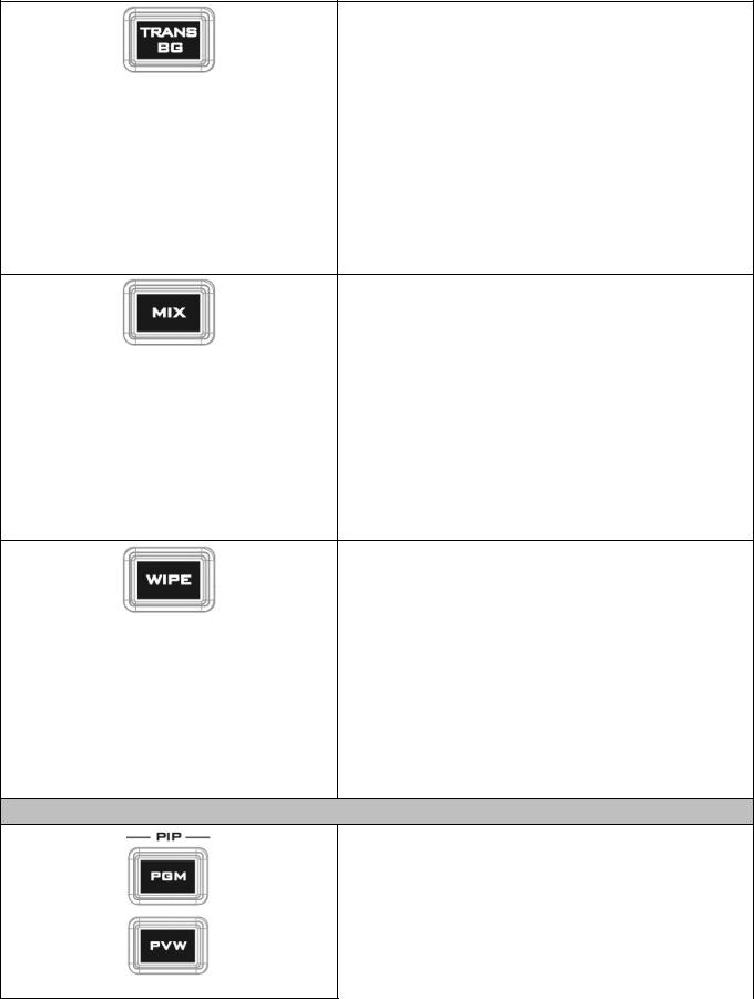
TRANS BG – Background Transition
The TRANS BG button enables Background Transition between Program / Preview. This feature is primarily used in Chromakeyer effect. When enabled, foreground and background will be switched together during transition. The background will be locked when the TRANS BG is disabeld, thus only the foreground is switched during the transition and the background will remain unchanged. If you would like to use the switcher function, please enable the “TRANS BG” function.
MIX Enable/Disable button
A MIX, also known as a dissolve, is a transition wherein the Program video is replaced by the Preview video at a smooth rate, and at the same time. Pressing the MIX button will enable the MIX transition effect and automatically disable the WIPE button. To activate the MIX effect, simply press the AUTO button or move the
T-Bar.
Transition time of the MIX Effect can be configured in the OSD MENU by selecting Start Transition.
WIPE Transition Effect Enable/Disable button
Pressing the WIPE button enables the WIPE transition effect after which the WIPE transition effect can be selected. To trigger the WIPE transition effect, simply press the AUTO button or move the T-Bar.
Wipe transition effect selection, border and position can be configured in the OSD menu (Start).
Note: When WIPE and MIX buttons are enabled at the same time, the SE-650 enters the Clip Transition mode.
PIP/Keyer
PIP Enable/Disable buttons
Picture in Picture puts the selected Sub Video Source in a window on the Main Program view, with control over window size and placement. For PIP configuration, please refer to the PIP section.
PIP PGM: Shows the configured PIP on multiview and
PGM outputs.
14
PIP PVW: Shows the configured PIP on PVW and multiview outputs. Holding down this button also allows selection of the PIP source from the Preview Source row. The selected source button will flash.
Note: You are also allowed to apply the chromakey effect to the PIP window. Please refer to the PIP section for chromakey configurations.
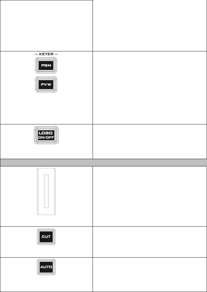
Keyer Enable/Disable buttons
KEYER PGM: Enables the key (Chroma / Luma / Linear) on multiview and PGM output
KEYER PVW: Enables Keyer on PVW and multiview outputs. Press and hold this button until the Preview Source row starts to flash and then select Keyer KEY or FILL sources from the Preview Source row.
Please refer to the Keyer section for keyer configurations.
Logo Enable/Disable button
The LOGO ON/OFF button enables the configured Logo on PVW and PGM outputs. Please configure the logo image source in the OSD. Refer to the Logo section for configuration details.
Transition Methods
T-Bar (Manual Transition)
T-Bar is used to manually perform a transition. PVW and PGM views can be transitioned at your preferred speed. To include the transition effect, simply press the
WIPE or MIX button, after which the Transition Effect will be trigger as you move the T-Bar.
CUT button
Pressing the Cut button performs immediate manual switch between PVW and PGM views without any transition effect.
AUTO button
Pressing the Auto button automatically transitions PVW and PGM views according to the selected speed and the configured transition effect. The AUTO transition effect can be configured in the Start option.
15
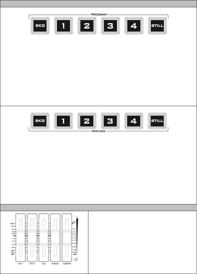
Program / Preview Outputs
Program Source Row
Pressing the number buttons along the PROGRAM row selects a video source for the PGM view.
BKG button: Pressing the BKG button will switch the background to the Matte background or color bars.
Still button: Pressing the STILL button will switch the Main Program view to a still picture, which can be selected in the OSD menu.
Note: Pressing the STILL button repeatedly alternates the Main Program view between Still 1 and Still 2 pictures.
Preview Source Row
Pressing the number buttons along the PROGRAM row selects a video source for the PGM view.
BKG button: Pressing the BKG button will switch the background to the Matte background or color bars.
Still button: Pressing the STILL button will switch the Main Program view to a still picture, which can be selected in the OSD menu.
Note: Pressing the STILL button repeatedly switches the Main Program view between Still 1 and Still 2 pictures.
Volume Control
Volume Adjustment Sliders
Sliders to control audio levels for the Main audio mixer.
MIC 1: Unbalanced MIC IN
MIC 2: Unbalanced MIC IN
AUX: RCA audio input (analog)
Digital: HDMI or SDI audio input (digital)
Master: Main audio output
16
Headphone Jack
Headphones jack accepts a stereo mini jack plug for stereo headphones. The headphone volume is controlled by the Headphone volume control knob.
Audio Meters
LED style meters, which show the signal strength at the Main Program Audio Output. The signal measured is determined by the level set with the Master slider. The LEDs turn red at +10 dB to indicate clipping distortion.
Audio Volume |
-20 |
|
-10 |
-8 |
|
-4 |
|
0 |
|
|
4 |
8 |
|
10 |
||||
(dBV) |
|
|
|
|
|
|
||||||||||||
|
|
|
|
|
|
|
|
|
|
|
|
|
|
|
|
|
|
|
LED Color |
|
G |
|
G |
G |
|
G |
|
G |
|
Y |
Y |
R |
|||||
Range (dBV) |
-20 |
|
-12 |
-11 |
|
-9.5 |
-8.5 |
|
-6.5 |
-5.5 |
-3 |
-2 |
1 |
2 |
5.5 |
6.5 |
8 |
9+ |
G: Green Y: Yellow |
|
R: Red |
|
|
|
|
|
|
|
|
|
|
|
|
|
|
||
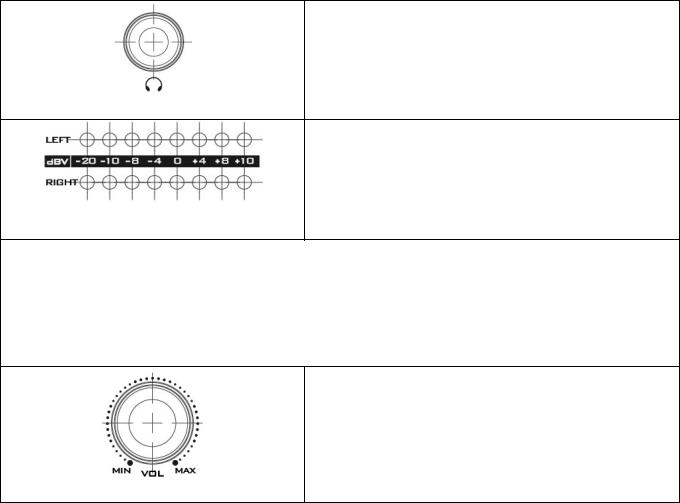
Headphone Volume Control Knob
Headphone volume control knob controls Headphone level with the MIN representing the minimum volume and MAX representing the maximum volume.
17
Chapter 3 Network Setup
The Ethernet port on the back panel of the SE-650 allows the user to import Still/Clip image or User memory using the Switcher Image Import/Export software discussed in Chapter 5. This chapter discusses direct connection between the SE-650 and your Windows computer as well as the remote setup in detail. Please note that the Switcher Image Import/Export software must be installed on your Windows-based computer before using this feature.
3.1Switcher Setup with a Windows Computer
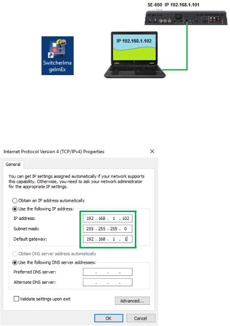
When new from the factory the SE-650 will initially have a static IP address of 192.168.1.101. The unit can be directly connected to a Windows-based computer using an RJ-45 ethernet cable. The following set up should allow you to initially configure the unit before moving it to an existing DHCP / LAN network.
•An RJ-45 Ethernet cable.
•Windows 7/8/10 laptop or PC.
•The Datavideo Switcher Image Import/Export software.
Instructions
1.First connect the SE-650 and the Windows computer together using an RJ-45 ethernet cable.
2.Turn on the Windows computer and set it to static IP setup within the Windows Network and Sharing Centre. In our example below the computer is given the following IP settings so that the computer matches the same IP range as the switcher.
3. Now install the Switcher Image Import/Export software to the computer.
18
3.2Installing the Switcher Image Import/Export software to a Windows Computer
The SE-650 can be connected to a simple IP network and accessed using Windows-based software. If you have not already set up the SE-650 with a computer then please follow the instructions in the previous section.
Please download the latest software from the Datavideo SE-650 web page. See: www.datavideo.com
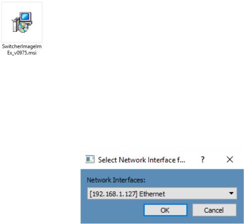
The install executable file [.msi] will be called SwitcherImageImEx_vXXXX.msi
The vXXXX represents the latest version number.
Double click this .msi file then follow the on screen install wizard prompts.
Once installed launch the Switcher Image Import/Export software.
The Switcher Image Import/Export software has a built-in IP finder, which is designed for PC with multiple Ethernet cards or DHCP network environment. Please note IP finder can only find devices that are on the same network domain as the PC. If you cannot remember your device IP, please press the RESET button to restore the default network settings. Upon launch of the Switcher Image Import/Export software, you will be prompted to select one Ethernet Interface Card.
Once selected, click OK to start the scanning process.
Note: Please make sure the selected interface card is on the same network domain as the SE-650 device.
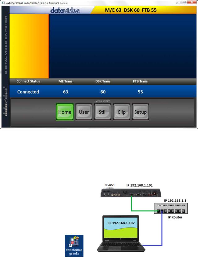
Once the SE-650 device is found, the software will connect with the switcher hardware over the IP set up described in the previous section. If the connection is successfully established, on the software user interface as shown in the diagram below, the Connect Status will show “Connected” (will display Not Connected if disconnected).
19
3.2.1 Router Based DHCP Setup
The computer software can also access the SE-650 over an existing TCP/IP LAN type network. In order to initially set up the SE-650, you may need the assistance of your local I.T. specialist to help with the network settings. To help guide you, we have included a simplified network setup example below, further advice may be available through your dealer locally or your Datavideo regional office.
To create this simple dedicated SE-650 IP network you will need:
•An IP router which can assign/give IP addresses.
•Two RJ-45 patch leads.
•Windows 7/8/10 laptop or PC.
•The IP router Administrator login and password.
•The Datavideo Switcher Image Import/Export software.
Instructions
1.First connect the router to the SE-650 and the Windows computer using two RJ-45 patch leads.
2.Turn on the Windows computer and set it to DHCP setup within the Windows Network and Sharing Centre.
3.Now click the Windows start button and run the CMD prompt window.
20
4.At the command line > : _ type IPCONFIG and press enter.
5.The DEFAULT GATEWAY number displayed should be the router’s current IP address.
6.Enter the DEFAULT GATEWAY IP address into the address bar of the computer’s web browser.
7.The web browser should display the login window for the router. Enter the router’s login and/or password.
The login details may be written on a sticker on the router itself or noted in the manual for the router.
8.Once logged into the router we need to change the router to supply IP addresses in the 192.168.1.xxx range. Use the router’s LAN Setup or Configure LAN option to set the router’s IP address as 192.168.1.1 and click save / apply.
9.Now reboot the router and power ON the SE-650.
10.Log into the router again using the web browser and the router’s new IP address 192.168.1.1
11.Use the router’s LAN Setup or Configure LAN option again, within this option there should be another option called Address Reservation or Client List.
12.The two devices connected to the router should be listed here, the computer and the SE-650.
13.The computer, because it is set for DHCP, will already have an IP address automatically assigned to it in this list.
14.The SE-650 will also be listed with its default IP address of 192.168.1.101 if it is not changed.
15.Click save / apply then reboot the router again.
16.Close the web browser and CMD windows.
17.Now install the Switcher Image Import/Export software to the computer.
3.2.2 Setting the Target IP Address with the Switcher Image Import/Export Software
Click Setup button in the MENU SELECT pane and the current IP Network settings are shown alongside the software version.
21
If the network settings are wrong then you may not be able to access the SE-650. Always keep a note of the last IP settings used and change these settings carefully to avoid problems.
Target IP address – This IP address is the location on the local network, or the internet, where the software can talk to the SE-650. By clicking the Target IP address you can enter a new address, once entered click Save Setup. The next time the Image Import/Export Software is opened, it will try to contact the switcher on this new Target IP address.
Network – This option in the yellow menu column allows you to change the network options on the SE-650. When delivered from the factory the default static IP settings should be:
Addr Mode: Static (a manually set IP address that does not change even after power cycling the SE-650 unit)
Target IP address: 192.168.1.101
Network Mask: 255.255.255.0 Gateway: 192.168.1.1
DHCP Setup - If the IP set up method is changed to DHCP then each time the SE-650 is started, it may be given a different IP address by the network. Only use this method if you know how to find the SE650 on the internal IP network. A device on the network (usually a router or server) will automatically assign an IP address to the SE-650. The other settings such as IP address, Subnet Mask and Gateway may appear blank within the Switcher Image Import/Export software as these would be automatically set by network router/DHCP server.
22
Chapter 4 OSD Menu
The switcher’s OSD menu allows the user to perform several configurations of image effects, such as Picture-in-Picture, keyers, downstream keys, still pictures and etc. The user can also configure the I/O by selecting the Inputs and Outputs options. In addition, in the setup option, the user is allowed to set the menu color, size, position and language.
The OSD Menu offers the user basic and advanced modes. The basic mode is generally a condensed version of the advanced menu mode. The following sub-sections will show you the various options available in these two modes.
4.1 Start
Start |
Transition |
M/E |
60 |
|
|
|
|
|
|
|
|
|
|
|
|
|
Type |
|
MIX |
|
|
|
|
|
|
|
|
|
|
|
|
|
|
|
|
|
|
|
|
|
Wipe Effects |
Wipe |
1 |
Soft |
0% |
Width |
1% |
|
Border |
Luma |
100% |
Sat |
80% |
Hue |
0 |
|
Position |
X |
0% |
Y |
0% |
|
|
|
|
|
|
|
|
|
|
|
Matte |
Luma |
100% |
Sat |
80% |
Hue |
0 |
4.1.1 Transition
The Transition sub-option allows the user to set the MIX effect duration, in frames. If the M/E is set to a value of 50 then the transition will take effect over a period of 50 frames or roughly 2 seconds. When the AUTO button is pressed, the transition will take the current M/E value defined by the user setting.
4.1.2 Type
The SE-650 provides three major types of transition effect, which are MIX, WIPE and Clip. Please note in addition to selecting the transition effect on the OSD menu, you are also allowed to press the MIX button, WIPE button or press MIX and WIPE buttons at the same time to enable the respective transition effects.
•If MIX is selected, set the transition duration in the “Transition” sub-option.
•If WIPE is selected, set the relevant WIPE settings in the “WIPE Effects” sub-option.
•If Clip, also known as the Stinger Effect, is selected, please load the clip in the “User Mems” sub-option.
4.1.3 Wipe Effects
This sub-option allows the user to select the Wipe Effect and configure the wipe’s border softness and width.
•Wipe – Selection of a WIPE effect from a set of 32 WIPE transition effects.
•Soft – A low value results in a solid edge border and a high value gives a soft diffused border.
•Width – A low value results in a thin border and a high value gives a wide border.
4.1.4 WIPE Border
In this sub-option, the user will be allowed to fine-tune the border color by adjusting the Luma,
Saturation and Hue values.
23
Note: Enable the WIPE border by setting the border width (Width) to a value greater than 0. The WIPE border is disabled when the border width is set to 0.
4.1.5 Position
Position allows the user to adjust the center position of some wipes (e.g Circle & Elipse). X represents the horizontal position and Y is the vertical position.
Horizontal Position (X)
Positive value moves the wipe center to the right. Negative value moves the wipe center to the left.
Zero value positions the wipe center at the screen center
Vertical Position (Y)
Positive value moves the wipe center up.
Negative value moves the wipe center down.
Zero value positions the wipe center at the screen center.
4.1.6 Matte
The user can configure the Matte by adjusting Luma, Saturation and Hue in this sub-option.
4.2 Keyer
Keyer of the SE-650 provides the user with the capability of image keying.
Advanced mode options
Keyer |
Keyer |
|
Chroma |
|
|
|
Self |
|
|
|
Priority |
|
Top |
||||
|
Keyer Ctrl |
|
Lift |
|
|
0% |
|
|
Gain |
|
1.0 |
|
|
Opac |
|
100% |
|
|
Key Source |
|
Input 1 |
|
|
|
Fill |
Black |
|
|
|
|
|
||||
|
|
|
|
|
|
|
|
|
|
|
|
|
|
||||
|
CK Setup |
|
CK Auto |
|
|
|
Hue |
140 |
|
|
Luma |
101% |
|
||||
|
|
|
K Range |
160 |
|
|
K Fgnd |
10% |
|
|
K Bgnd |
90% |
|
||||
|
|
|
Hi-Light |
|
|
0% |
|
|
Lo-Light |
|
0% |
|
|
Bg-Supp |
|
OFF |
|
|
|
|
|
|
|
|
|
|
|
|
|
||||||
|
|
|
|
|
|
|
|
|
|
|
|
|
|
|
|||
|
Mask |
|
Left |
0% |
|
|
Right |
0% |
|
|
|
|
|
|
|||
|
|
|
Top |
|
|
0% |
|
|
Bot |
|
0% |
|
|
|
|
|
|
4.2.1 Keyer
There are three keying modes available: Linear, Luma, and Chroma.
Linear keying mode is usually chosen for sharp images. For non-sharp images, please select Luma keying. Chroma keying mode allows you to remove the green or blue backdrop from the image.
After the keying mode is chosen, select Self if only one source is enabled for the keyer, which is Key source. Select Split if two sources are enabled for the keyer, which are Key and Fill sources.
Priority sets the key image to either the top layer or bottom layer.
4.2.2 Keyer Control
“Keyer Control” adjusts lift, gain and opacity of the key image. Lift adjusts the dark/black areas of the key image.
24
 Loading...