


HD 12-Channel
DIGITAL VIDEO SWITCHER
SE-3200
Instruction Manual
|
|
Table of Contents |
|
FCC COMPLIANCE STATEMENT.......................................................................................... |
6 |
||
WARNINGS AND PRECAUTIONS........................................................................................ |
6 |
||
WARRANTY ...................................................................................................................... |
|
7 |
|
STANDARD WARRANTY................................................................................................................. |
7 |
||
THREE YEAR WARRANTY............................................................................................................... |
7 |
||
DISPOSAL ......................................................................................................................... |
|
8 |
|
CHAPTER 1 |
INTRODUCTION............................................................................................ |
9 |
|
1.1 |
SYSTEM ARCHITECTURE ................................................................................................... |
10 |
|
1.2 |
MAIN UNIT OVERVIEW.................................................................................................... |
11 |
|
1.3 |
CONTROL PANEL OVERVIEW ............................................................................................. |
13 |
|
1.4 |
CONNECTING THE POWER SUPPLY ..................................................................................... |
15 |
|
CHAPTER 2 |
PREPARATION............................................................................................ |
16 |
|
2.1 |
CONNECTING DEVICES..................................................................................................... |
16 |
|
Connecting the Video and Audio Input Devices................................................................ |
16 |
||
When linking via tally connection..................................................................................... |
17 |
||
Connecting the Video and Audio Output Devices............................................................. |
17 |
||
Connecting to a Network.................................................................................................. |
18 |
||
2.2 |
MULTI VIEW.................................................................................................................. |
18 |
|
CHAPTER 3 NETWORK AND SOFTWARE SETUP FOR SWITCHER ..................................... |
21 |
||
3.1 |
SWITCHER SETUP WITH A WINDOWS COMPUTER.................................................................. |
21 |
|
3.2 |
INSTALLING THE SWITCHER IMAGE IMPORT/EXPORT SOFTWARE TO A WINDOWS COMPUTER ........ |
22 |
|
Installation........................................................................................................................ |
22 |
||
Router Based DHCP Setup................................................................................................. |
26 |
||
Setting the Target IP Address with the Switcher Image Import/Export Software............ |
27 |
||
CHAPTER 4 |
OSD MENU................................................................................................. |
30 |
|
4.1 |
START .......................................................................................................................... |
36 |
|
Transition.......................................................................................................................... |
37 |
||
Type .................................................................................................................................. |
|
37 |
|
Wipe Effects...................................................................................................................... |
37 |
||
WIPE Border...................................................................................................................... |
37 |
||
Position ............................................................................................................................. |
|
37 |
|
Matte ................................................................................................................................ |
|
38 |
|
4.2 |
KEYER .......................................................................................................................... |
38 |
|
Keyer ................................................................................................................................. |
|
38 |
|
Keyer Control .................................................................................................................... |
39 |
||
Key Source......................................................................................................................... |
39 |
||
2
Fill Source.......................................................................................................................... |
40 |
|
Invert................................................................................................................................. |
41 |
|
Mask ................................................................................................................................. |
41 |
|
4.3 |
CHROMA ...................................................................................................................... |
41 |
Keyer ................................................................................................................................. |
41 |
|
Key Source......................................................................................................................... |
41 |
|
CK Setup............................................................................................................................ |
42 |
|
Mask ................................................................................................................................. |
43 |
|
4.4 P-IN-P ......................................................................................................................... |
43 |
|
Keyer ................................................................................................................................. |
43 |
|
Position ............................................................................................................................. |
44 |
|
Border ............................................................................................................................... |
44 |
|
Shade Matte (Dual Color Border) ..................................................................................... |
45 |
|
Crop................................................................................................................................... |
46 |
|
4.5 |
FLEX SRC....................................................................................................................... |
46 |
Flex Screen ........................................................................................................................ |
46 |
|
Quick ................................................................................................................................. |
47 |
|
4.6 |
INPUTS ......................................................................................................................... |
48 |
Input.................................................................................................................................. |
49 |
|
Proc Amp........................................................................................................................... |
49 |
|
Audio................................................................................................................................. |
49 |
|
Crosspoint ......................................................................................................................... |
49 |
|
Audio XPT.......................................................................................................................... |
49 |
|
4.7 |
OUTPUTS ...................................................................................................................... |
50 |
Outputs ............................................................................................................................. |
50 |
|
Multiviewer....................................................................................................................... |
51 |
|
Tally Mode ........................................................................................................................ |
51 |
|
GPI Out.............................................................................................................................. |
52 |
|
4.8 |
AUDIO.......................................................................................................................... |
52 |
Audio................................................................................................................................. |
52 |
|
PGM Audio........................................................................................................................ |
53 |
|
Analog Out........................................................................................................................ |
53 |
|
4.9 |
FILES............................................................................................................................ |
53 |
User Mems........................................................................................................................ |
54 |
|
|
Load Memory................................................................................................................ |
54 |
|
Save Memory ................................................................................................................ |
54 |
Still .................................................................................................................................... |
54 |
|
|
Load Still........................................................................................................................ |
54 |
|
Save Still ........................................................................................................................ |
55 |
|
Grab Still........................................................................................................................ |
56 |
|
Loading still images....................................................................................................... |
56 |
Clip .................................................................................................................................... |
57 |
|
|
Load Clip........................................................................................................................ |
57 |
|
|
3 |
|
Clip Settings................................................................................................................... |
58 |
|
|
Loading the existing Clip for Stinger Transition Effect.................................................. |
58 |
|
4.10 |
SETUP .......................................................................................................................... |
58 |
|
Standard ........................................................................................................................... |
59 |
||
Menu Mode ...................................................................................................................... |
59 |
||
Menu Preference .............................................................................................................. |
59 |
||
Level.................................................................................................................................. |
|
59 |
|
Keyboard........................................................................................................................... |
60 |
||
Auto Save.......................................................................................................................... |
60 |
||
Factory Default ................................................................................................................. |
60 |
||
Language .......................................................................................................................... |
60 |
||
Network |
............................................................................................................................ |
60 |
|
Software |
............................................................................................................................ |
60 |
|
CHAPTER 5 |
BASIC OPERATION...................................................................................... |
61 |
|
5.1 |
VIDEO SWITCHING .......................................................................................................... |
61 |
|
Program and Preset rows ................................................................................................. |
61 |
||
Black and MATTE View ..................................................................................................... |
61 |
||
Flex Output ....................................................................................................................... |
62 |
||
Still button ........................................................................................................................ |
62 |
||
5.2 |
TRANSITIONS ................................................................................................................. |
62 |
|
WIPE Selection MENU....................................................................................................... |
64 |
||
REV Button........................................................................................................................ |
65 |
||
5.3 |
MANAGING STILL PICTURES.............................................................................................. |
65 |
|
Grabbing & Saving a Still to memory ............................................................................... |
65 |
||
Loading an existing Still from memory ............................................................................. |
66 |
||
Deleting a saved Still from memory.................................................................................. |
66 |
||
FS – Frame Store Button ................................................................................................... |
66 |
||
Export/Import Still Images to/from the PC....................................................................... |
67 |
||
|
How to use .................................................................................................................... |
67 |
|
5.4 PERFORMING A STINGER TRANSITION ................................................................................. |
70 |
||
Loading a Clip from memory ............................................................................................ |
70 |
||
How to Create the PNG Sequence for Stinger Transition Effect ....................................... |
70 |
||
|
Adobe After Effects....................................................................................................... |
71 |
|
|
Adobe Media Encoder CC ............................................................................................. |
73 |
|
|
Important things to note while creating Stinger Transition Effects ............................. |
76 |
|
Importing the Clip for Stinger Transition Effect from the PC............................................ |
77 |
||
CHAPTER 6 |
ADVANCED OPERATION ............................................................................. |
80 |
|
6.1 PICTURE-IN-PICTURE AND DOWNSTREAM KEY ..................................................................... |
81 |
||
Picture-In-Picture .............................................................................................................. |
81 |
||
|
Assigning a video source to a PIP window.................................................................... |
82 |
|
|
Assigning a video source to a PIP window using shortcut keys.................................... |
83 |
|
4
Downstream Key............................................................................................................... |
83 |
|
6.2 PLACING TEXT ON THE VIDEO USING LUMA KEY ..................................................................... |
84 |
|
6.3 INSERTION OF PEOPLE ONTO BACKGROUNDS (CHROMA KEY) .................................................. |
86 |
|
6.4 DISPLAYING A VARIETY OF SOURCES AT THE SAME TIME .......................................................... |
89 |
|
Basic Flex™ Output (Four PIP Windows)........................................................................... |
89 |
|
Assigning a video source to a PIP window using shortcut keys.................................... |
92 |
|
Simultaneously Display up to Eight PIP Windows ............................................................ |
92 |
|
CHAPTER 7 |
APPENDICES............................................................................................... |
95 |
APPENDIX 1 |
TALLY OUTPUTS ...................................................................................................... |
95 |
APPENDIX 2 |
GPI / GPO CONNECTIONS ....................................................................................... |
97 |
APPENDIX 3 |
FIRMWARE UPDATE................................................................................................. |
98 |
T-Bar Re-Calibration ......................................................................................................... |
98 |
|
APPENDIX 4 |
FREQUENTLY-ASKED QUESTIONS.............................................................................. |
100 |
APPENDIX 5 |
DIMENSIONS & WEIGHT......................................................................................... |
101 |
APPENDIX 6 |
SPECIFICATIONS .................................................................................................... |
102 |
SERVICE AND SUPPORT ................................................................................................ |
104 |
|
Disclaimer of Product & Services
The information offered in this instruction manual is intended as a guide only. At all times, Datavideo Technologies will try to give correct, complete and suitable information. However, Datavideo Technologies cannot exclude that some information in this manual, from time to time, may not be correct or may be incomplete. This manual may contain typing errors, omissions or incorrect information. Datavideo Technologies always recommend that you double check the information in this document for accuracy before making any purchase decision or using the product. Datavideo Technologies is not responsible for any omissions or errors, or for any subsequent loss or damage caused by using the information contained within this manual. Further advice on the content of this manual or on the product can be obtained by contacting your local Datavideo Office or dealer.
5

FCC Compliance Statement
This device complies with part 15 of the FCC rules. Operation is subject to the following two conditions:
(1)This device may not cause harmful interference, and
(2)This device must accept any interference received, including interference that may cause undesired operation.
Warnings and Precautions
1.Read all of these warnings and save them for later reference.
2.Follow all warnings and instructions marked on this unit.
3.Unplug this unit from the wall outlet before cleaning. Do not use liquid or aerosol cleaners. Use a damp cloth for cleaning.
4.Do not use this unit in or near water.
5.Do not place this unit on an unstable cart, stand, or table. The unit may fall, causing serious damage.
6.Slots and openings on the cabinet top, back, and bottom are provided for ventilation. To ensure safe and reliable operation of this unit, and to protect it from overheating, do not block or cover these openings. Do not place this unit on a bed, sofa, rug, or similar surface, as the ventilation openings on the bottom of the cabinet will be blocked. This unit should never be placed near or over a heat register or radiator. This unit should not be placed in a built-in installation unless proper ventilation is provided.
7.This product should only be operated from the type of power source indicated on the marking label of the AC adapter. If you are not sure of the type of power available, consult your Datavideo dealer or your local power company.
8.Do not allow anything to rest on the power cord. Do not locate this unit where the power cord will be walked on, rolled over, or otherwise stressed.
9.If an extension cord must be used with this unit, make sure that the total of the ampere ratings on the products plugged into the extension cord do not exceed the extension cord rating.
10.Make sure that the total amperes of all the units that are plugged into a single wall outlet do not exceed 15 amperes.
11.Never push objects of any kind into this unit through the cabinet ventilation slots, as they may touch dangerous voltage points or short out parts that could result in risk of fire or electric shock. Never spill liquid of any kind onto or into this unit.
12.Except as specifically explained elsewhere in this manual, do not attempt to service this product yourself. Opening or removing covers that are marked “Do Not Remove” may expose you to dangerous voltage points or other risks, and will void your warranty. Refer all service issues to qualified service personnel.
13.Unplug this product from the wall outlet and refer to qualified service personnel under the following conditions:
a. When the power cord is damaged or frayed;
6

b.When liquid has spilled into the unit;
c.When the product has been exposed to rain or water;
d.When the product does not operate normally under normal operating conditions. Adjust only those controls that are covered by the operating instructions in this manual; improper adjustment of other controls may result in damage to the unit and may often require extensive work by a qualified technician to restore the unit to normal operation;
e.When the product has been dropped or the cabinet has been damaged;
f.When the product exhibits a distinct change in performance, indicating a need for service.
Warranty
Standard Warranty
Datavideo equipment is guaranteed against any manufacturing defects for one year from the date of purchase.
The original purchase invoice or other documentary evidence should be supplied at the time of any request for repair under warranty.
The product warranty period beings on the purchase date. If the purchase date is unknown, the product warranty period begins on the thirtieth day after shipment from a Datavideo office.
All non-Datavideo manufactured products (product without Datavideo logo) have only one year warranty from the date of purchase.
Damage caused by accident, misuse, unauthorized repairs, sand, grit or water is not covered under warranty.
Viruses and malware infections on the computer systems are not covered under warranty.
Any errors that are caused by unauthorized third-party software installations, which are not required by our computer systems, are not covered under warranty.
All mail or transportation costs including insurance are at the expense of the owner.
All other claims of any nature are not covered.
All accessories including headphones, cables, batteries, metal parts, housing, cable reel and consumable parts are not covered under warranty.
Warranty only valid in the country or region of purchase.
Your statutory rights are not affected.
Three Year Warranty
All Datavideo products purchased after July 1st, 2017 qualify for a free two years extension to the standard warranty, providing the product is registered with Datavideo within 30 days of purchase.
7

Certain parts with limited lifetime expectancy such as LCD panels, DVD drives, Hard Drive, Solid State Drive, SD Card, USB Thumb Drive, Lighting, Non-PCIe Card and third party provided PC components are covered for 1 year.
The three-year warranty must be registered on Datavideo's official website or with your local Datavideo office or one of its authorized distributors within 30 days of purchase.
Disposal
For EU Customers only - WEEE Marking
This symbol on the product or on its packaging indicates that this product must not be disposed of with your other household waste. Instead, it is your responsibility to dispose of your waste equipment by handing it over to a designated collection point for the recycling of waste electrical and electronic equipment. The separate collection and recycling of your
waste equipment at the time of disposal will help to conserve natural resources and ensure that it is recycled in a manner that protects human health and the environment. For more information about where you can drop off your waste equipment for recycling, please contact your local city office, your household waste disposal service or the shop where you purchased the product.
CE Marking is the symbol as shown on the left of this page. The letters "CE" are the abbreviation of French phrase "Conformité Européene" which literally means "European Conformity". The term initially used was "EC Mark" and it was officially replaced by "CE Marking" in the Directive
93/68/EEC in 1993. "CE Marking" is now used in all EU official documents.
8
Chapter 1 Introduction
SE-3200 is a 12 channel professional digital video switcher with real Full 1080p/60 (3G) High Definition support, featuring 12 digital inputs including 8 SDI and 4 HDMI inputs with embedded audio, 6 SDI and 3 HDMI outputs for connecting HD recorder, external monitors and etc.
SE-3200 is a lightweight switcher solution with the main unit mountable on the 19 inch rack. The control keyboard panel can be placed on a flat surface or built inside an outdoor broadcast van.
The SE-3200 also has powerful, easy-to-use effects, such as Chroma / Luma Key, DSK, PIP, DVE / Wipe Generator, still stores, and logo insertion.
Major five features
Up to 8 PIP windows with four displaying FLEX sources
Flexible combinations of 4 USKs and 2 DSKs
Original 1080p (3G) operation
Supports 4 broadcast quality chromakeyers and 50 virtual studio background images
16 stinger transitions
Summary of all features
A total of 12 Video Input Interfaces (8 x SDI / 4 x HDMI)
9 Video Outputs (6 x SDI / 3 x HDMI)
4 Upstream Keyers, supporting Chroma key & Linear / Luma key
4 PIP (assignable to any of keyers)
2 DSK supporting Linear & Luma Key Modes
2 Logo insertions (Animation logo with adjustable position and size / logo size is determined by the imported file)
Wipe, Mix, DVE, Cut and Stinger Transitions
32 Wipe patterns including Circle & Heart, and Border & Softness Control
Clip player (150 Frames) for Stinger Transitions
Any Input (1-12) can be used as a Frame store (Stills Store)
Support XPT (Cross Point Assignment)
4 x XLR Analogue Audio Inputs
2 x XLR De-embedded Analogue Audio Outputs
Tally output
USB Port for FW upgrade
9
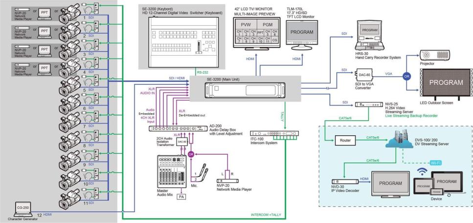
1.1 System Architecture
10
1.2 Main Unit Overview
The power button starts and shuts down both the SE-3200 main unit and its attached keyboard.
The front panel on the SE-3200 main unit has a grille for two airflow cooling fans. Please do not block or cover this grille as the unit may overheat. This grille should also be kept free of dust.
The front panel can be removed by removing the four thumbscrews. A soft brush or cloth can then be used to clean the grille before attaching it back to the unit.
11
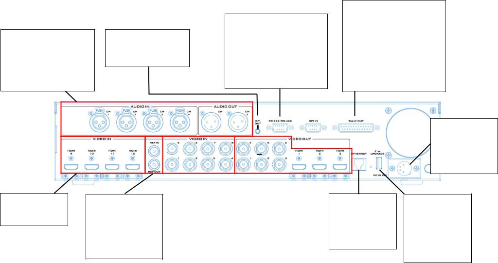
AUDIO OUT
Supports two channels of the XLR Balanced Audio output.
AUDIO IN
Supports four channels of the XLR Balanced Audio Input.
See Section 4.8 Audio for audio setup.
GPI OUT
The GPI socket can be used for simple external control.
See Appendix 2 for more details.
RS-232/422 REMOTE
In addition to the Ethernet port for remote control, you can also connect your PC to this port for controlling the SE-3200 with the Switcher Image Import/Export Software. See Sections 3.2, 5.3 and 5.4 for details.
Please check with your local Datavideo office for advice on this connection.
TALLY OUT
The SE-3200 Tally Output port provides bicolour tally information to a number of other Datavideo products, such as the ITC100 eight channel talkback system or the Datavideo TLM range of monitors.
Tally OUT can also be configured to an audio mixer port for receiving external audio signals.
See Appendix 1 for more details.
DC IN
Connect the supplied 12 V PSU to this 4 PIN XLR socket
Pin 1 = GND ( - ) Pin 2 = NC
Pin 3 = NC
Pin 4 = VCC ( + )
HDMI Video Inputs 9 – 12
HDMI Video Inputs 9-12 The HDMI inputs are labelled 9~12.
SYNC I/O
The HS-3200 can be synchronized with other studio equipment such as cameras. REF IN accepts Tri-level or Black Burst sync. REF LOOP can be used to pass the sync signal to other studio equipment such as cameras or recorders.
|
|
|
|
|
|
SDI Video Inputs 1 – 8 |
|
SDI/HDMI Video Outputs |
|||
The lower row of |
|
The SDI/HDMI video outputs |
|||
SD/HD-SDI inputs are |
|
are user-defined outputs. Each |
|||
labelled 1~4. The upper |
|
of these outputs has the |
|||
row of SD/HD SDI inputs |
|
option to be: |
|||
are labelled 5~8. |
|
|
Multiview |
||
|
|
|
|
Program |
|
|
|
||||
|
|
|
|
Preview |
|
|
|
|
|
Program + DSK |
|
|
|
|
|
Clean Program |
|
|
|
|
|
Clean Preview |
|
|
|
|
Input 1 – 12 |
||
|
|
|
|
|
|
Ethernet Port
Used to connect the switcher to the PC or laptop so that the unit can be controlled remotely via PC software (Switcher
Image Import/Export Software).
USB FW Upgrade Port
Connect the USB drive containing the switcher’s latest firmware files to this port and start the firmware upgrade process on the OSD MENU.
Note: See Firmware Update section for details.
12

1.3 Control Panel Overview
Perform video switching and other relevant controls on the Control Panel.
User Memory Buttons |
|
|
|
|
|
|
|
|
|
User Memory buttons 1/2 allow |
|
|
|
|
|
|
|
|
|
the user to quickly recall and load |
|
|
|
|
|
|
|
|
|
previously saved switcher |
|
OSD Menu Control |
|
Keyer Selection |
|
|
Logos 1 & 2 |
|
|
settings with a single button |
|
|
|
|
|
||||
|
|
|
|
Logo insertion on |
|
|
|||
|
Menu control buttons for |
|
Enabling the pre-assigned |
|
|
|
|
||
press. |
|
|
|
|
|
||||
|
|
|
|
preview and program |
|
|
|||
|
opening the OSD menu on |
|
keyers (Chroma, Luma, |
|
|
|
|
||
|
|
|
|
|
|
||||
|
|
|
|
|
outputs once enabled. |
|
|
||
Press and hold the SHIFT button |
|
the monitor and navigating |
|
Linear, DSK and PIP) on |
|
|
|
|
|
|
|
|
|
|
|
DSK Selection |
|||
and then press USER 1 or 2 |
|
through the OSD menu. |
|
Program and Preset views. |
|
|
|
|
|
|
|
|
|
|
|
Enabling DSK on preview |
|||
|
|
|
|
|
|
|
|
||
button to switch to User Memory |
|
|
|
|
|
|
|
|
|
|
|
|
|
|
|
|
|
and program outputs. |
|
|
|
|
|
|
|
|
|
||
3 or 4. |
|
|
|
|
|
|
|
|
|
|
|
|
|
|
|
|
|
|
|
|
|
|
|
|
|
|
|
|
|
|
|
|
|
|
|
|
|
|
|
|
|
|
|
|
|
|
|
|
|
|
|
|
|
|
|
|
|
|
|
|
|
|
|
|
|
|
|
|
|
|
|
|
Transition Effect |
|
|
|
|
|
|
|
|
|
|
|
|
|
|
|
|
Selection |
|
|
|
|
|
|
|
|
|
|
|
|
|
|
|
|
Selection of 2D and |
|
|
|
|
|
|
|
|
|
|
|
|
|
|
|
|
3D transition effects. |
Frame Store |
|
|
|
|
|
|
|
|
|
|
|
|
|
|
|
|
|
|
|
|
|
|
|
|
|
|
|
|
|
|
|
||
Press the FS button |
|
|
|
|
|
|
|
|
|
|
|
|
|
|
|
|
and then press a |
|
|
|
|
|
|
|
|
|
|
|
|
|
|
Transition Type |
|
channel button on |
|
|
|
|
|
|
|
|
|
|
|
|
Selection |
|||
the Preview row to |
|
|
|
|
|
|
|
|
|
|
|
|
|
|
Selection of Clip, MIX |
|
switch the selected |
|
|
|
|
|
|
|
|
|
|
|
|
|
|
or WIPE transition |
|
channel to a pre- |
|
|
|
|
|
|
|
|
|
|
|
|
|
|
effect. |
|
|
|
|
|
|
|
|
|
|
|
|
|
|
||||
loaded still picture. |
|
|
|
|
|
|
|
|
|
|
|
|
|
|
|
|
|
|
|
|
|
|
|
|
|
|
|
|
|
|
|||
|
|
|
|
|
|
|
|
|
|
|
|
|
|
|
||
|
|
|
|
|
|
|
|
|
|
|
|
|
|
|
|
|
|
|
|
|
|
|
|
|
|
|
|
|
|
|
|
|
FTB – Fade To Black |
|
|
|
|
|
|
|
|
|
|
|
|
|
|
|
|
|
|
|
|
|
|
|
|
|
|
|
|
|
|
|
|
|
Fades the program |
|
|
|
|
|
|
|
|
|
|
|
|
|
|
|
|
view to black once |
|
|
|
|
|
|
|
|
|
|
|
|
|
|
|
||
|
|
|
|
|
|
|
|
|
|
|
|
|
|
|
|
pressed. |
|
|
|
|
|
|
|
|
|
|
|
|
|
|
|
|
|
|
|
|
|
|
|
|
|
|
|
|
|
|
|
|
|
|
|
|
|
|
|
|
|
|
|
|
|
|
|
|
|
|
|
T-Bar – Manual |
|
|
|
|
|
Program Row (PGM) |
|
Preview Row (PVW) |
|
Transition |
|
CUT |
|
AUTO TAKE |
|
|
Selection of program |
|
Selection of preview |
|
Move the T-Bar up or |
|
A hard cut between |
|
Press to trigger |
|
|
|
|
|
|
||||||
|
video source. |
|
video source. |
|
down to switch between |
|
video sources. |
|
automatic transition. |
|
|
|
|
|
|
|
Preview and Program. |
|
|
|
|
|
|
|
|
|
|
|
|
|
|
|
|
|
|
|
|
|
|
|
|
|
|
13
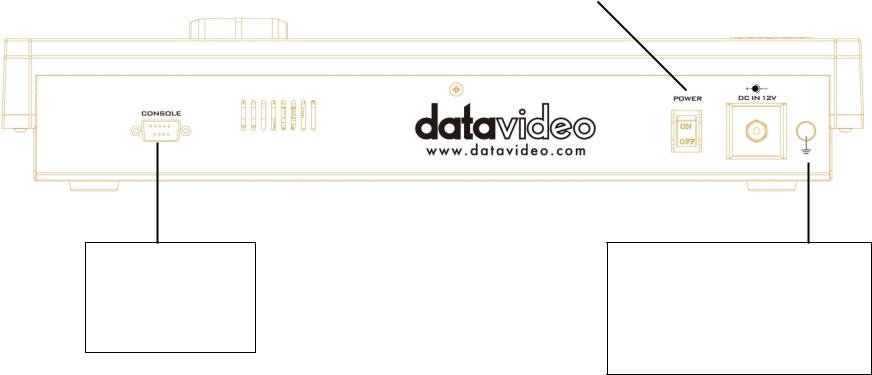
CONSOLE
This 9pin D-Sub connector is used to connect the Control Panel / Keyboard to the rear of the SE-3200 Main Processing unit.
The power button |
|
DC IN 12V |
|
starts and shuts down |
|
Connect the supplied |
|
the control panel / |
|
12V PSU to the power |
|
keyboard power. |
|
socket. |
|
|
|
|
|
|
|
|
|
Grounding Terminal
When connecting this unit to any other component, make sure that it is properly grounded by connecting this terminal to an appropriate point. When connecting, use the socket and be sure to use wire with a crosssectional area of at least 1.0 mm2.
14
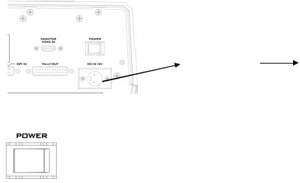
1.4 Connecting the Power Supply
Connect the DC output plug of the supplied AC adapter to the DC IN 12V connector on the rear of the switcher and then connect the AC adapter to a power supply.
AC Adapter |
Power Supply |
|
|
To start, turn ON the power switch.
To shut off the machine, simply turn OFF the power switch.
15
Chapter 2 Preparation
In this chapter, we will describe various essential devices to be connected to the switcher in order to complete the system setup. If you possess the skills for setting up the production system, feel free to skip this chapter and proceed to Chapter 5: Basic Operation.
2.1 Connecting Devices
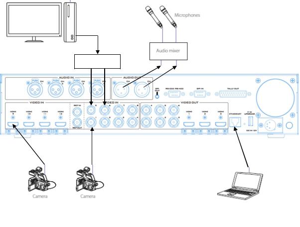
Connecting the Video and Audio Input Devices
Connect cameras, computers and other video input devices to the video input connectors on the rear of the unit and connect an audio mixer to audio input connectors.
Computer for text input
TC-200
Computer for remote control of the switcher
16
When linking via tally connection
Connect the switcher’s tally connector to the tally connector on a commercially available tally box.
Tally Box
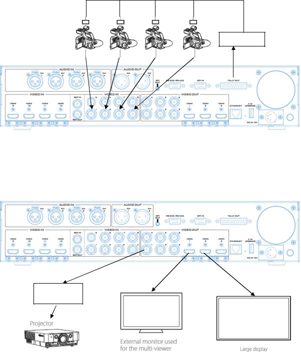
Connecting the Video and Audio Output Devices
Connect projectors, large displays and other video output devices to the video output connectors on the rear of the switcher.
SDI-to-HDMI
Converter
17
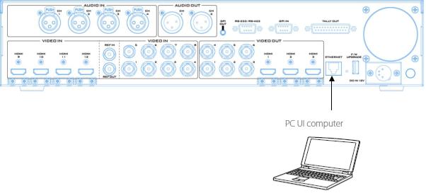
Connecting to a Network
Use the Ethernet Port to connect the switcher to the PC with the Image Import/Export Software installed.
For details on the Switcher Image Import/Export Software, see Chapter 3.
2.2 Multi View
The SE-3200 Multi view output can be supplied from the HDMI or SDI outputs, see Chapter 4 (4.7) for configuring the outputs. The Multi view shows monitoring images for Preview (PVW), Program (PGM) and Inputs 1~12. The Multi view can also show audio level bars overlaid on the Program image. This confirms the analogue XLR audio input is being received and embedded to the selected Program output(s).
SE-3200 Multi-view is supplied from the HDMI connection(s) on the rear panel and available across multiple HDMI monitors (not supplied). Since a variety of multi-image layouts is available, these HDMI outputs can be used to monitor video and audio in a number of different configurations. The layout of the multi view can also be changed. The sources can be swapped around using the cross point section of the Inputs menu. For each setup, embedded audio level indication is available on the Preview and Program windows.
The diagrams below depict four different multi-view layouts available on the SE-3200.
18
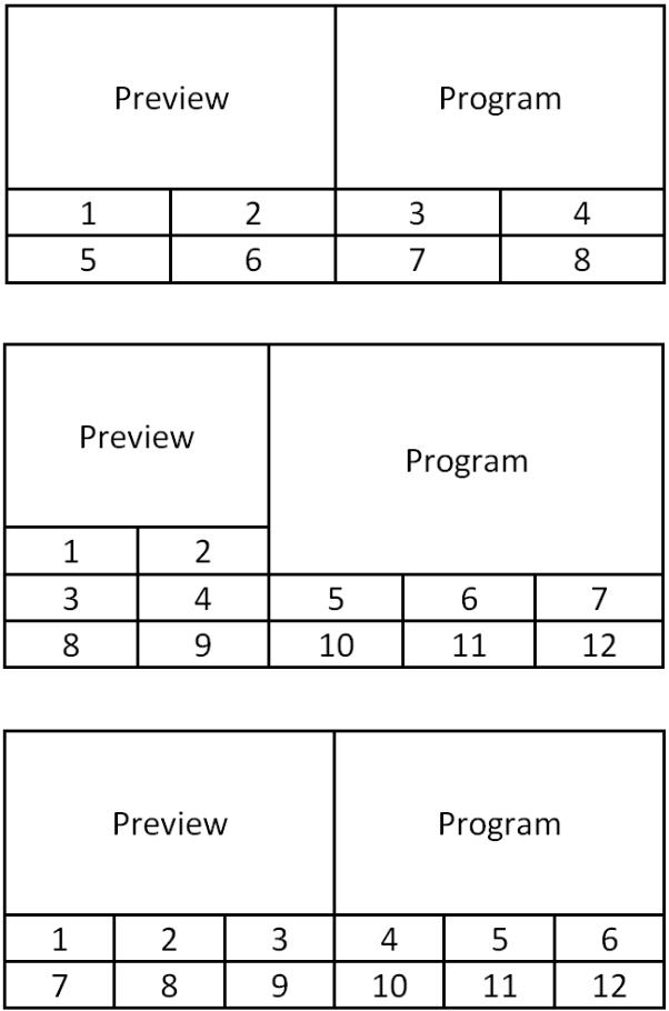
Mode 1:
Mode 2:
Mode 3:
19

Mode 4:
A Red tally indication box is shown around the selected Program source. This video image is also seen at the switcher’s selected Program output(s). A Green tally indication box is shown around the selected Preview source. This will be the image source to be mixed to, wiped in or cut to next depending on the user’s preference.
20
Chapter 3 Network and Software Setup for Switcher
The Ethernet port on the back panel of the SE-3200 allows the user to import Still/Clip image or User memory using the Switcher Image Import/Export software. This chapter discusses direct connection between the SE-3200 and your Windows computer as well as the remote setup in detail. Please note that the Switcher Image Import/Export software must be installed on your Windows-based computer before using this feature.
Section 3.1 discusses how you can establish direct connection between the SE-3200 and a Windows computer. In Section 3.2, we will show you how to access the SE-3200 on the PC with the Switcher Image Import/Export software.
3.1 Switcher Setup with a Windows Computer
When new from the factory the SE-3200 will initially have a static IP address of 192.168.100.101. The unit can be directly connected to a Windows-based computer using an RJ-45 ethernet cable. The following set up should allow you to initially configure the unit before moving it to an existing DHCP / LAN network.
An RJ-45 Ethernet cable.
Windows 7/8/10 laptop or PC.
The Datavideo Switcher Image Import/Export software.
Instructions
1.First connect the SE-3200 and the Windows computer together using an RJ-45 ethernet cable.
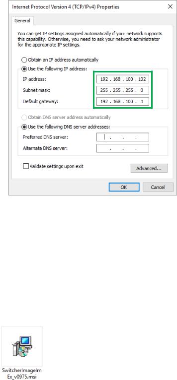
2.Turn on the Windows computer and set it to static IP setup within the Windows Network and Sharing Centre. In our example, the computer is given the following IP settings so that the computer matches the same IP range as the switcher.
21
3. Now install the Switcher Image Import/Export software to the computer.
3.2 Installing the Switcher Image Import/Export software to a Windows Computer
The SE-3200 can be connected to a simple IP network and accessed using Windows-based software. If you have not already set up the SE-3200 with a computer then please follow the instructions in the previous section.
Please download the latest software from the Datavideo SE-3200 web page. See: www.datavideo.com
The install executable file [.msi] will be called
SwitcherImageImEx_vXXXX.msi
The vXXXX represents the latest version number.
Double click this .msi file then follow the on screen install wizard prompts.
Installation
1.Download SwitcherImageImEx_vx.x.x.msi from the product page and save it on the local disk.
2.Click the installation file icon to start the Setup Wizard.
3.Click “Next”
22
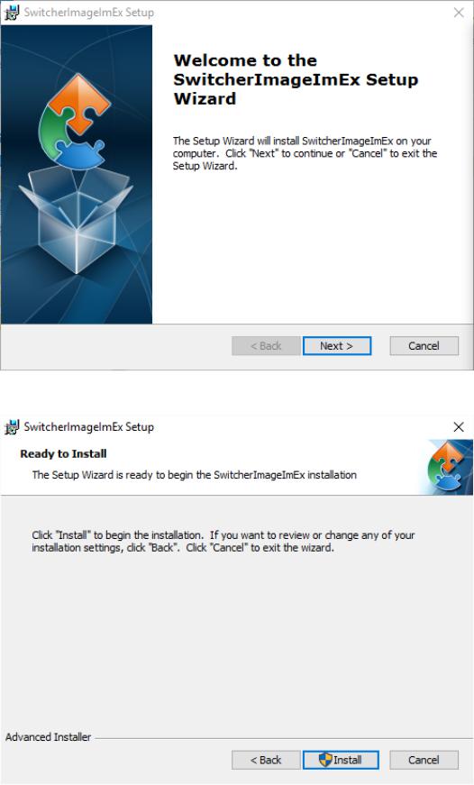
4. Click “Install”
5.When you see the safety warning requesting for permission to allow an unknown publisher to make changes to the PC, please click “Yes” to continue.
23
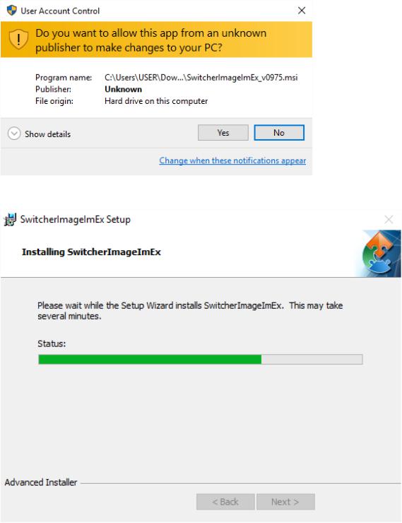
6. Wait for the installation to finish.
7.After the setup is complete, you will see the following window; check “Launch SwitcherImageImEX” and click “Finish” to open the program.
24
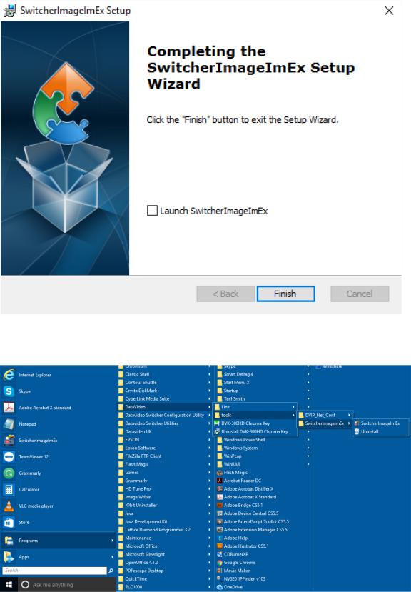
8.After the setup is finished, a shortcut will be created in Start Menu > Programs > datavideo > tools > SwitcherImageImEx
9. Click SwitcherImageImEx to open the program.
The Switcher Image Import/Export software has a built-in IP finder, which is designed for PC with multiple Ethernet cards or DHCP network environment. Please note IP finder can only find devices that are on the same network domain as the PC. If you cannot remember
25
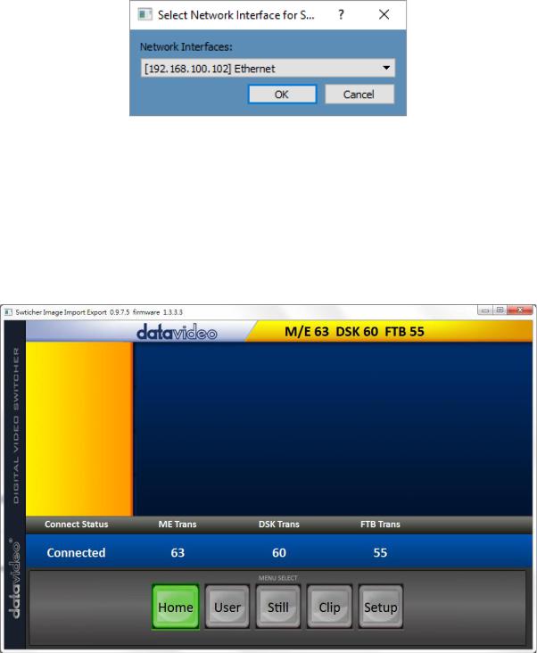
your device IP, simply open the OSD menu and then go to the Setup sub menu to restore the default network settings. Upon launch of the Switcher Image Import/Export software, you will be prompted to select one Ethernet Interface Card.
Once selected, click OK to start the scanning process.
Note: Please make sure the selected interface card is on the same network domain as the SE-3200 device.
Once the SE-3200 device is found, the software will connect with the switcher hardware over the IP set up described in the previous section. If the connection is successfully established, on the software user interface as shown in the diagram below, the Connect Status will show “Connected” (will display Not Connected if disconnected).
Router Based DHCP Setup
The computer software can also access the SE-3200 over an existing TCP/IP LAN type network. In order to initially set up the SE-3200, you may need the assistance of your local I.T. specialist to help with the network settings. To help guide you, we have included a simplified network setup example below, further advice may be available through your dealer locally or your Datavideo regional office.
26
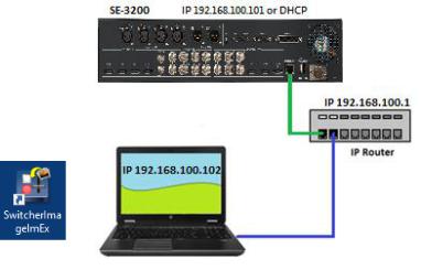
To create this simple dedicated SE-3200 IP network you will need:
An IP router which can assign/give IP addresses.
Two RJ-45 patch leads.
Windows 7/8/10 laptop or PC.
The IP router Administrator login and password.
The Datavideo Switcher Image Import/Export software.
Instructions
1.First connect the router to the SE-3200 and the Windows computer using two RJ-45 patch leads.
2.Turn on the Windows computer and set it to DHCP setup within the Windows Network and Sharing Centre.
3.Now click the Windows start button and run the CMD prompt window.
4.At the command line > : _ type IPCONFIG and press enter.
5.The DEFAULT GATEWAY number displayed should be the router’s current IP address.
6.Press the MENU button on the SE-3200 control panel to open the OSD menu on the connected Multiview monitor. Open the Network sub menu of the Setup menu and then change the Addr Mode to DHCP from the default Static IP. Move to the SAVE option and then press the ENTER button to save new settings.
7.Reboot the SE-3200 and after the machine is rebooted, open the Network sub menu by following the instructions outlined in the previous step. The IP Addr option should show an IP address assigned randomly by the router thus having identical network domain as the router. If you see an IP address of 0.0.0.0 in the IP Addr field, it is likely that the router requires longer time to assign an IP address to the connected devices. Close the Network sub menu and reopen after 30-60 seconds, you should be able to see the newly assigned IP address.
8.Now install the Switcher Image Import/Export software to the computer.
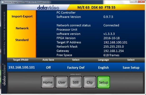
Setting the Target IP Address with the Switcher Image Import/Export Software
Click Setup button in the MENU SELECT pane and the current IP Network settings are shown alongside the software version.
27
If the network settings are wrong then you may not be able to access the SE-3200. Always keep a note of the last IP settings used and change these settings carefully to avoid problems.
Target IP address – This IP address is the location on the local network, or the internet, where the software can talk to the SE-3200. By clicking the Target IP address you can enter a new address, once entered click Save Setup. The next time the Image Import/Export Software is opened, it will try to contact the switcher on this new Target IP address.
Network – This option in the yellow menu column allows you to change the network options on the SE-3200. When delivered from the factory the default static IP settings should be:
Addr Mode: Static (a manually set IP address that does not change even after power cycling the SE-3200 unit)
Target IP address: 192.168.100.101
Network Mask: 255.255.255.0
Gateway: 192.168.100.1
DHCP Setup - If the IP set up method is changed to DHCP then each time the SE-3200 is started, it may be given a different IP address by the network. Only use this method if you know how to find the SE-3200 on the internal IP network. A device on the network (usually a router or server) will automatically assign an IP address to the SE-3200. The other settings such as IP address, Subnet Mask and Gateway may appear blank within the Switcher Image Import/Export software as these would be automatically set by network router/DHCP server.
28
The software supports multiple languages which are English, Traditional Chinese and Simplified Chinese.
Note: The latest software version can be downloaded from the product page. To update the software, it is recommended to remove the existing program first. Click “Start Menu > Programs > datavideo > tools > Uninstall” to remove the program. If the program is not removed, the user will be prompted that the PC already contains the same program during the reinstallation process. Click “Remove” to remove SwitcherImageImEx from your computer.
29

Chapter 4 OSD MENU
The switcher’s OSD menu allows the user to perform several configurations of image effects, such as Picture-in- Picture, chroma key, subtitle overlay, still pictures and etc. The user can also configure the I/O by selecting different input and output options. In addition, in the setup menu, the user is allowed to set the menu color, size, position and language.
The OSD Menu can be opened in basic or advanced mode. The basic mode is generally a condensed version of the advanced menu mode. The following sub-sections will show you the various options available in these two modes.
Overview
|
Main |
|
|
Sub-Options |
|
|
|
Parameters |
|
|
Options |
|
|
|
|
|
|
||
|
|
|
|
|
|
|
|
|
|
|
|
|
|
Transition |
|
M/E |
Mix Effect (0 - 9999 Default: 15) |
||
|
|
|
|
|
DSK |
Downstream Key Effect (0 - 9999 Default: 15) |
|||
|
|
|
|
(Duration) |
|
||||
|
|
|
|
|
FTB |
Fade-to-Black Effect (0 - 9999 Default: 60) |
|||
|
|
|
|
|
|
|
|||
|
|
|
|
|
|
|
DVE |
|
|
|
|
|
|
Type |
|
Clip |
|
|
|
|
|
|
|
|
Wipe |
|
|
||
|
|
|
|
|
|
|
|
|
|
|
|
|
|
|
|
|
Mix |
|
|
|
|
|
|
|
|
|
Wipe |
Wipe Effect Presets (1 - 32 Default: 1) |
|
|
|
|
|
Wipe Effects |
|
Soft |
Border Softness (0 - 100% Default: 0%) |
||
|
|
|
|
|
|
|
Width |
Border Width (0 - 100% Default: 1%) |
|
Start |
|
|
|
|
Luma |
Border Color Luma (0 - 100% Default: 100%) |
|||
|
|
|
|
Border |
|
Sat |
Border Color Saturation (0 - 100% Default: |
||
|
|
|
|
|
80%) |
|
|||
|
|
|
|
|
|
|
|
|
|
|
|
|
|
|
|
|
Hue |
Border Color Hue (0 - 355 +/-5 Default: 0) |
|
|
|
|
|
Position |
|
X |
Horizontal Position (0 - 1600% Default: 0%) |
||
|
|
|
|
|
Y |
Vertical Position (0 - 1600% Default: 0%) |
|||
|
|
|
|
|
|
|
|||
|
|
|
|
|
|
|
Luma |
Background Matte Luma (0 - 100% Default: |
|
|
|
|
|
|
|
|
100%) |
|
|
|
|
|
|
|
|
|
|
|
|
|
|
|
|
Matte |
|
Sat |
Background Matte Saturation (0 - 100% |
||
|
|
|
|
|
|
|
Default: 80%) |
||
|
|
|
|
|
|
|
|
||
|
|
|
|
|
|
|
Hue |
Background Matte Hue (0 - 355 +/-5) |
|
|
|
|
|
|
|
|
DSK 2 |
|
|
|
|
|
|
|
|
|
DSK 1 |
|
|
|
|
|
|
Keyer |
|
Key 4 |
Keyer Selection (Default: Key 4) |
||
|
|
|
|
|
Key 3 |
||||
|
|
|
|
|
|
|
|
|
|
Keyer |
|
|
|
|
Key 2 |
|
|
||
|
|
|
|
|
|
|
Key 1 |
|
|
|
|
|
|
|
|
|
Chroma |
|
|
|
|
|
|
Keyer Ctrl |
|
Luma |
Type of Keyer (Default: Linear) |
||
|
|
|
|
|
|
|
Linear |
|
|
30
 Loading...