

Page 1
Application Specific Discretes
A.S.D.
FEATURES
n DEDICATED THYRISTOR STRUCTURE FOR
CAPACITANCE DISCHARGE IGNITION
OPERATION
n HIGH PULSE CURRENT CAPABILITY
240A @tp= 10µs
BENEFITS
n SPACE SAVING THANKS TO MONOLITHIC
FUNCTION INTEGRATION
n HIGH RELIABILITY WITH PLANAR
TECHNOLOGY
TM
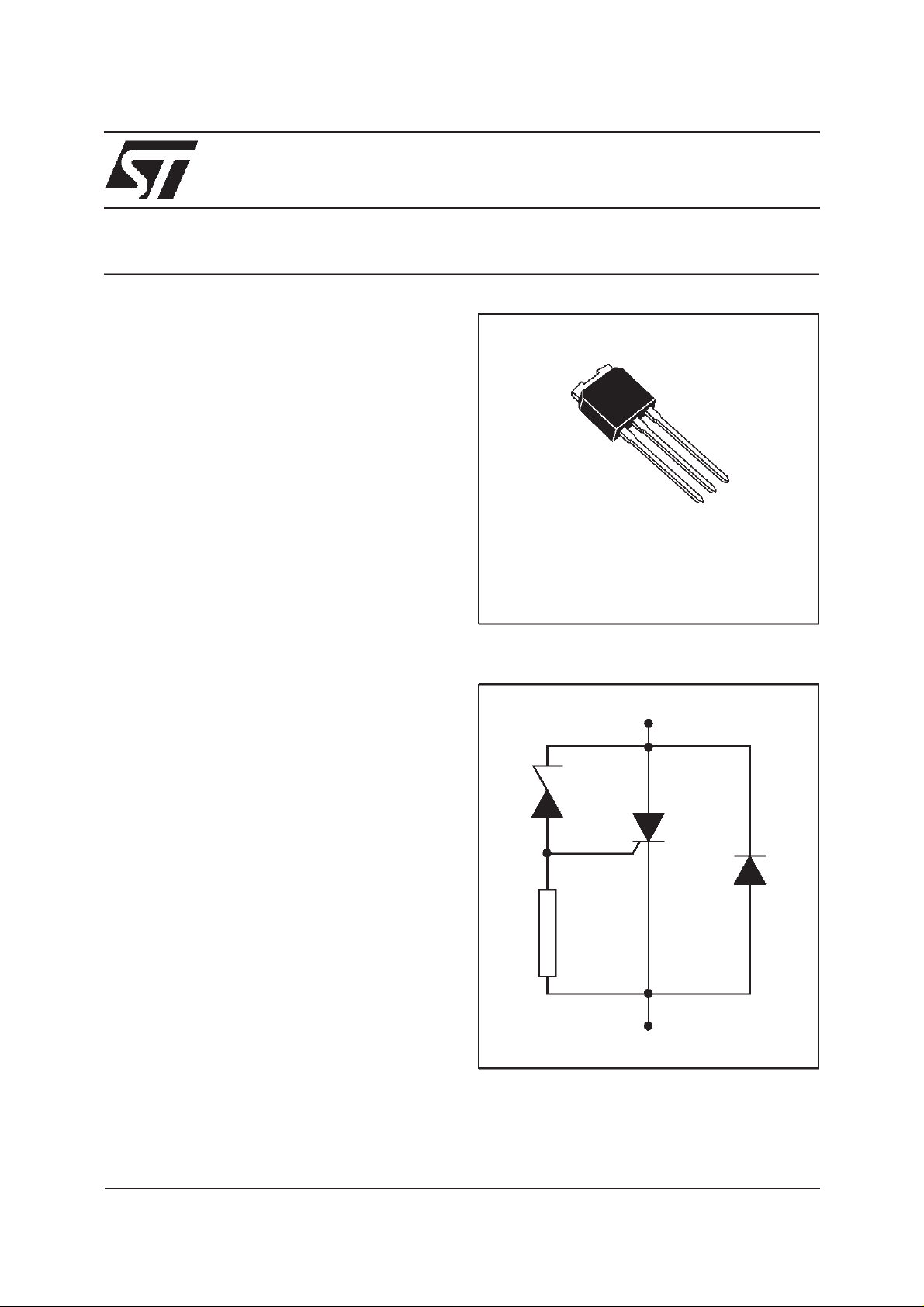
FLC10-200H
FIRE LIGHTER CIRCUIT
TAB
3
2
1
IPAK
DESCRIPTION
The FLC10 series have been developed especially for high powercapacitance dischargeoperation. The main applications are gas lighter or
ignitor such as :
cookers / gas boilers / gas hobs...
It uses a high performance planar diffused technology adapted to high temperature and rugged
environmental conditions.
Th : Thyristor for switching operation.
Z : Zener diode to set the thresholdvoltage.
D : Diodefor reverseconduction.
R :2kΩresistor.
FUNCTIONAL DIAGRAM
pin 2
Z
Th
D
R
pin 1/3 (*)
(*)Pin1 and Pin3 must be shorted together in
the application circuit layout.
Jun 2000 - Ed: 5D
1/7
Page 2
FLC10-200H
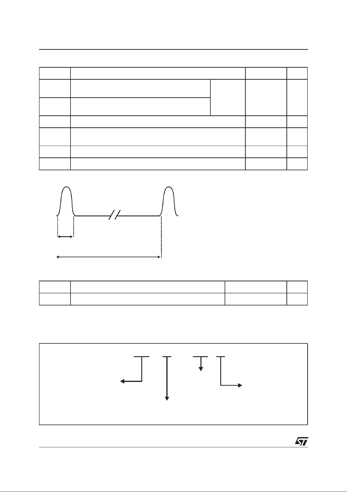
ABSOLUTE RATINGS (limiting values)
Symbol Parameter Value Unit
I
TRM
I
FRM
dI/dt
Tstg
Tj
Repetitive surge peak on state current for thyristor
-30°C ≤ T
amb
≤ 120°C
Repetitive surge peak on state current for diode
-30°C ≤ T
amb
≤ 120°C
Critical rate of rise time on state current -30°C ≤ T
Storage junction temperature range
Maximum junction temperature
amb
tp =10µs
( note 1)
≤ 120°C
240 A
200 A/µs
- 40 to + 150
+ 125
Toper Operating temperature range -30 + 120 °C
T
L
Note 1: Test current waveform
Maximum lead temperature for soldering during 10s 260 °C
10µs
200ms
°C
THERMAL RESISTANCE
Symbol Parameter Value Unit
Rth(j-a) Thermal resistance junction to ambient 100 °C/W
ORDERING INFORMATION
FLC 10 - 200 H
RM
200: V = 200V
FIRE LIGHTER CIRCUIT
CIRCUIT NUMBER:
SCR + diode + Zener + Resistance
High PowerVersion
2/7
PACKAGE H: IPAK
Page 3
FLC10-200H
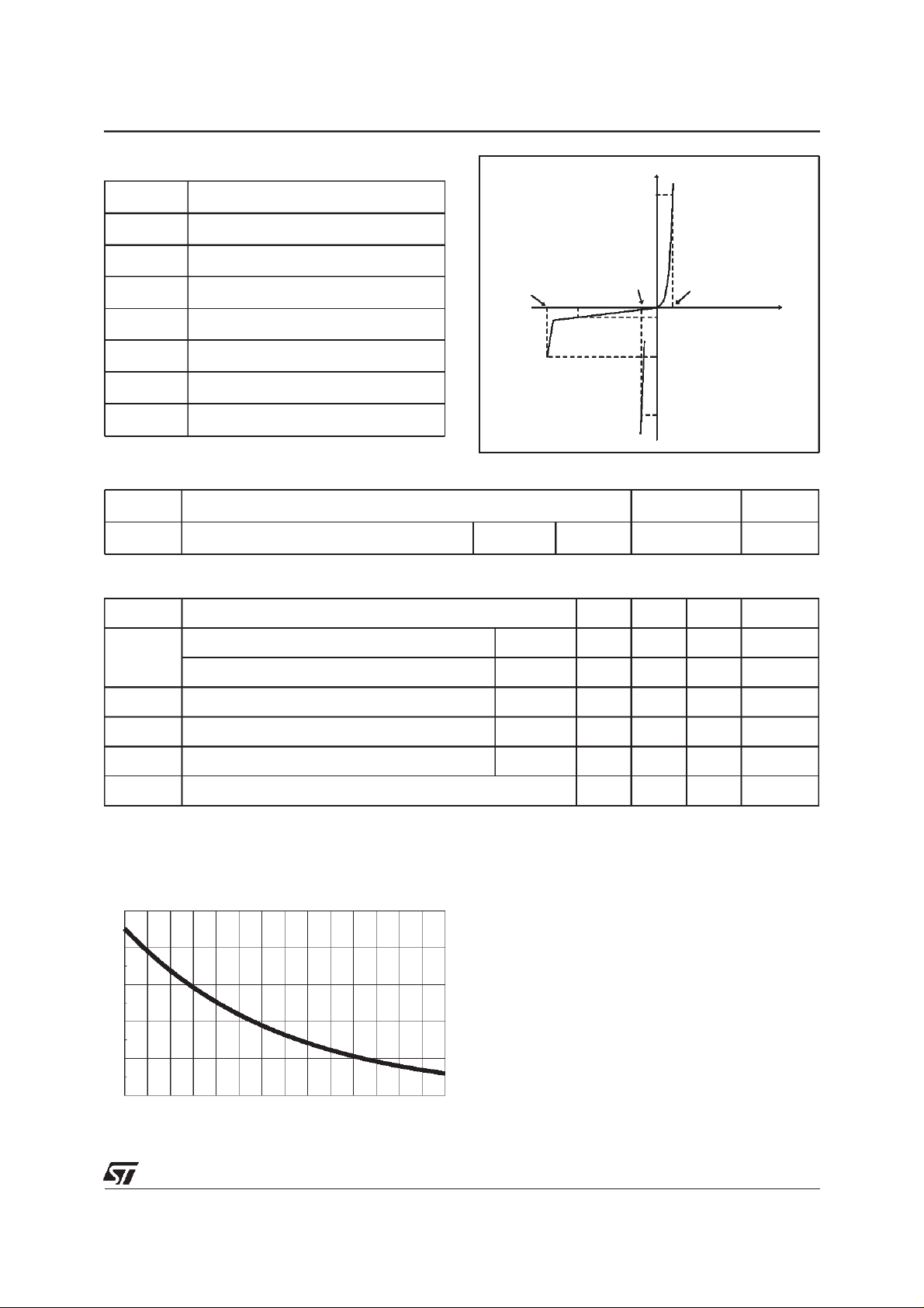
ELECTRICAL CHARACTERISTICS
Symbol Parameters
V
V
V
V
I
I
RM
αT
RM
BO
T
F
BO
Stand-off voltage
Breakover voltage
On-state voltage
Diode forward voltagedrop
Breakover current
Leakage current
Temperature coefficient for V
BO
V
BO
V
RM
I
I
F
V
T
I
RM
I
BO
I
V
F
T
DIODE (D) PARAMETER
Symbol Test Conditions Value Unit
V
F
IF=2A tp≤500µsTj=25°C Max. 1.7 V
THYRISTOR (Th) and ZENER (Z) PARAMETERS
V
Symbol Test conditions Min Typ Max Unit
I
RM
VRM= 200 V Tj =25°C10µA
Tj = 125°C 100 µA
V
BO
I
BO
V
T
at I
at V
BO
BO
Tj =25°C 200 225 250 V
Tj =25°C 0.5 mA
IT=2A tp≤500µsTj=25°C 1.7 V
αT 0.3 V/°C
Fig.1: Relative variation of breakover current
versus junctiontemperature.
k = I (Tj) / I (25°C)BO BO
2.5
2
1.5
1
0.5
0
-20 0 20 40 60 80 100
Tj (°C)
3/7
Page 4

FLC10-200H
Fig. 2: BASIC APPLICATION
Rs Ds
AC
Ic
Ic
t
c
Th
Z
MAINS
The applications of the lighter using the capacitance discharge topology operate in 2phases :
PHASE 1
The energy coming from the mains is stored into
thecapacitorC.Forthat, theACvoltageis rectified
by the diode Ds.
COMPONENT CHOICE
D
R
PHASE 2
At the end of the phase 1, the voltage across the
capacitor C reaches the avalanche threshold of
the zener. Thena current flowsthrough the gate of
the thyristor Th which fires.
The firing of the thyristor causes an alternating
current to flow through the capacitor C.
The positive parts of this current flow through C,
Th and the primary of the HV transformer.
The negative parts of the current flow through C,
D and t he primaty of the HV transformer.
RS RESISTOR CALCULATION
The Rs resistor allows, in addition with th e capacitor C, to adjust the spark frequency and to limi t the
current from themains. Itsvalue shall allow the thyristor Th tofireeven in worst case conditions. Inthis
borderline case, thesystem must fire with the lowest value of RMS mains voltage whilethe breakdown
voltage and current of the FLC are at the maximum.
The maximumRs value is equal to :
Rs
max
( min. ) [ max .( .( ))]
AC BO amb
=
−+−2125α
kI
.*
BO
VVTT
* : see fig 1
4/7
Page 5

Fig. 3 : Spark frequency versus Rs and C
FLC10-200H
F (Hz)
20
10
5
3
2
1
4.7 6.8 10 12 15 18 22 27 30
The couple Rs/C can be chosen with the previous
curve. Keep in mind the Rs maximum limit for
which the system would not work when the AC
Vac=220Vrms,Vbo=225V,Tamb=25°C
C=0.47
C=0.47
µ
µ
F
F
C=1
C=1
µ
µ
F
F
µ
µ
F
F
C=3.3
Ω
Rs (k )
C=2.7
µ
F
C=2.2
µ
F
C=1.5
C=1.5
µ
F
mains is minimum. The next curve shows the behavior with Rs=15kΩ and C=1µF.
Fig. 4: Voltage across the capacitance with Rs = 15kΩ,C=1µF and VBO= 225V.
5/7
Page 6

FLC10-200H
PEAK CURRENT LIMIT
This co mponen t i s des igned t owiths tan d
I
= 240A for a pulse duration of 10µsforan
TRM
ambient temperature of120°C inrepetitivesurge
(see note 1, page 2).
Fig. 5: Peak current limit versus pulse duration.
I (A)
TRM
300
280
260
240
220
200
The curv e of peak current v ers us th e pulse
duration allows us t o verify if the application
is w ithin the FLC operating limit.
Tj max :120°C
180
6 8 10 12
tp (µs)
POWER LOSSES (For 10µs, see note1)
To evaluate the power losses, please use the following equations :
For the thyristor : P = 1.18 x I
For the diode : P = 0.67 x I
F(AV)
T(AV)
+ 0.106 I
+ 0.035 I
2
T(RMS)
2
F(RMS)
14
6/7
Page 7

PACKAGE MECHANICAL DATA
IPAK
E
B2
H
L1
L
B6
G
L2
B3
B
V1
B5
FLC10-200H
REF. DIMENSIONS
Millimeters Inches
Min. Typ. Max. Min. Typ. Max.
A 2.2 2.4 0.086 0.094
A1 0.9 1.1 0.035 0.043
A
C2
A1
C
A3
A3 0.7 1.3 0.027 0.051
B 0.64 0.9 0.025 0.035
B2 5.2 5.4 0.204 0.212
B3 0.85 0.033
B5 0.3 0.035
D
B6 0.95 0.037
C 0.45 0.6 0.017 0.023
C2 0.48 0.6 0.019 0.023
D 6 6.2 0.236 0.244
E 6.4 6.6 0.252 0.260
G 4.4 4.6 0.173 0.181
H 15.9 16.3 0.626 0.641
L 9 9.4 0.354 0.370
L1 0.8 1.2 0.031 0.047
L2 0.8 1 0.031 0.039
V1 10° 10°
Type Marking Package Weight Base qty Delivery mode
FLC10-200H
Information furnishedis believedtobe accurate andreliable. However,STMicroelectronicsassumes no responsibilityfor theconsequences of
use ofsuch informationnor forany infringementof patentsor otherrights ofthird partieswhich mayresult fromits use. Nolicense isgranted by
implication or otherwise under any patent or patent rights of STMicroelectronics. Specifications mentioned in this publication are subject to
change without notice.This publication supersedes and replacesall information previously supplied.
STMicroelectronics products are not authorized foruse as critical components in life supportdevices or systems without express written approval of STMicroelectronics.
Australia - Brazil -China - Finland - France - Germany - Hong Kong - India - Italy - Japan - Malaysia
FLC10-200H IPAK 0.350g 75 Tube
The ST logoisa registered trademark of STMicroelectronics
2000STMicroelectronics - Printed inItaly -All rights reserved.
STMicroelectronics GROUP OF COMPANIES
Malta -Morocco - Singapore - Spain - Sweden -Switzerland - United Kingdom - U.S.A.
http://www.st.com
7/7
 Loading...