


ST/SV 3210 & ST/SV 3306
Operator’s Manual
CG Triumvirate is a trademark of Agfa Corporation.
Copyright Information:
Firmware (Software) Agreement
The enclosed Firmware (Software) resident in the EPROM’s is owned by Licensor or its suppliers and is licensed for used only on a single printer in the user’s Trade or Business.
The User agrees not to, and not to authorize or permit any other person or party to, duplicate or copy the EPROM’s or the information contained in the EPROM’s. The firmware (Software) is protected by applicable copyright laws and Licensor retains all rights not expressly granted. In no event will Licensor or its suppliers be liable for any damages or loss, including direct, incidental, economic, special, or consequential damages, arising out of the use or inability to use the Firmware (Software).
Information in this document is subject to change without notice and does not represent a commitment on the part of Datamax Barcode Products Corporation. No part of this manual may be reproduced or transmitted in any form or by any means, for any purpose other than the purchaser's personal use, without the expressed written permission of Datamax Corporation.
All rights reserved. Printed in the United States of America. © Copyright 2002 by Datamax Corporation
Part Number: 88-2240-01
Revision: E


Agency Compliance and Approvals:
UL1950 Information Technology Equipment
C22.2 No. 950-M93
C 
 US
US
Listed
EN60950
For 230 Volt Operation (Europe): Use a cord set, marked "HAR," consisting of a min H05VV-F cord which has a minimum 0.75 square mm diameter conductors, provided with an IEC 320 receptacle and a male plug for the country of installation rated 6A, 250V
Für 230 Volt (Europa): Benützen Sie ein Kabel, das mit "HAR" markiert ist, bestehend mindestens aus einem H05VV-F Kabel, das mindestens 0,75 Quadratmillimeter Drahtdurchmesser hat; sowie eine IEC320 Steckdose und einen für das Land geeigneten Stecker, 6A, 250 Volt.
As an Energy Star Partner, the manufacturer has determined that this product meets the Energy Star guidelines for energy efficiency.
The manufacturer declares under sole responsibility that this product conforms to the following standards or other normative documents:
EMC: EN55022 (1993) Class B EN50082-1 (1992) EN61000-3-2 (1995) EN61000-3-3 (1995)
IEC 801-2 (1991), 8kV CD; 15kV AD IEC 801-3 (1984), 3 V/m
IEC 801-4 (1988), 500V Signal Lines 1kV AC Power Lines
EN 55024 (1998) SV Model Only
Safety: This product complies with the requirements of EN 60950/A11:1997
Gost-R
FCC: This device complies with FCC CFR 47 Part 15 Class A.
þ Note: This equipment has been tested and found to comply with the limits for a Class A digital device, pursuant to Part 15 of the FCC Rules. These limits are designed to provide reasonable protection against harmful interference when the equipment is operated in a commercial environment. This equipment generates, uses, and can radiate radio frequency energy, and if not installed and used in accordance with the instructions in this manual, it may cause harmful interference to radio communications. Operation of this equipment in a residential area is likely to cause harmful interference in which case the user will be required to correct the interference at his own expense.
Important Safety Instructions:
This printer has been carefully designed to give many years of safe and reliable performance; however, as with all types of electronic equipment, there are some basic precautions that should taken to avoid personal injury or damage to the printer:
ØCarefully read the installation and operating instructions provided with this printer.
ØRead and follow all warning instruction labels on the printer.
ØPlace ST Model printers on a flat, firm surface; mount SV Model printers in a flat, rigid enclosure.
ØTo protect the printer from overheating, make sure no openings on the printer are blocked.
ØDo not place the printer on or near a heat source.
ØDo not use the printer near water and never spill liquid into it.
ØEnsure that the power source meets the ratings listed on the printer; if uncertain, check with your dealer, electrician, or utility company.
ØDo not place the power cord where it may be walked on. Should the power cord becomes damaged or frayed, replace it immediately.
ØOnly qualified, trained service technicians should attempt to repair this printer.

Contents
Printer Overview
1.0 About the Printer ........................................................... |
1 |
|
1.0.1 |
Standard Features........................................... |
2 |
1.0.2 |
Optional Features............................................ |
3 |
Getting Started
2.0 Unpacking the Printer ................................................... |
5 |
|
2.0.1 |
Inspection ........................................................ |
6 |
2.0.2 |
Additional Requirements ................................. |
6 |
Setting up the Printer
3.0 |
AC Voltage Configuration ............................................. |
7 |
|
3.1 |
Interfacing the Printer.................................................... |
8 |
|
3.2 |
Loading Ticket Stock................................................... |
10 |
|
|
3.2.1 |
ST Models ..................................................... |
10 |
|
3.2.2 |
SV Models ..................................................... |
12 |
3.3 |
Installing a Memory Module ........................................ |
13 |
|
3.4 |
Using the Front Panel ................................................. |
14 |
|
3.5 |
Resident Formats........................................................ |
17 |
|
|
3.5.1 |
Configuration Ticket....................................... |
17 |
|
3.5.2 |
Test Pattern Ticket ........................................ |
18 |
|
3.5.3 |
Internal Test Ticket ........................................ |
19 |
3.6 |
Resetting the Printer ................................................... |
20 |
|
|
3.6.1 |
Warm Reset .................................................. |
20 |
|
3.6.2 |
Factory Default Reset.................................... |
20 |
Adjusting and Maintaining the Printer
4.0 TOF Sensor Adjustment ............................................. |
21 |
4.0.1 ST Model ....................................................... |
22 |
i

|
4.0.2 |
SV Model ....................................................... |
23 |
4.1 |
Stock ID Selections..................................................... |
24 |
|
4.2 |
Start of Print & Cut/Tear Adjustment........................... |
26 |
|
4.3 |
Operational Database Modification............................. |
27 |
|
|
4.3.1 |
Database Modification Example .................... |
30 |
4.4 |
Maintenance ............................................................... |
31 |
|
|
4.4.1 |
Cleaning the Printhead .................................. |
32 |
|
4.4.2 Cleaning the Platen Roller............................. |
33 |
|
|
4.4.3 |
TOF Sensor Cleaning.................................... |
34 |
|
4.4.4 Ticket Detect Sensor Cleaning ...................... |
35 |
|
|
4.4.5 |
Interior Cleaning ............................................ |
36 |
|
4.4.6 |
Exterior Surface Cleaning.............................. |
36 |
Troubleshooting
5.0 |
Troubleshooting Tips .................................................. |
37 |
5.1 |
Hex Dump Mode ......................................................... |
41 |
Specifications
6.0 |
Specifications.............................................................. |
43 |
6.1 |
Approved Ticket Stocks .............................................. |
47 |
Appendix A
ASCII Control Code Chart................................................... |
49 |
Appendix B
Available Fonts and Barcodes ............................................ |
51 |
Appendix C
Cable Listings ..................................................................... |
61 |
Appendix D
SV Model Mounting Dimensions......................................... |
63 |
ii

Warranty Information.................................................. |
65 |
Glossary .......................................................................... |
69 |
Index................................................................................. |
73 |
iii

iv
Printer Overview
1.0About the Printer
ST (Table) Model |
SV (Vertical) Model |
The ST-3210, SV-3210, ST-3306 and SV-3306 printers, hereafter referred to as ‘the printer’, blend rugged design with state-of-the-art electronics and user-friendly features to redefine industry printer standards.
This printer is equipped with a 32-bit microprocessor and four megabytes of standard memory to process complicated formats quickly and easily. Auto-detecting communication ports ensure that interfacing to the host system is a simple task. In addition, the versatile front panel functions and automatic loading system will speed you through all setup changes.
This manual provides all the information necessary for the daily operation of the printer. To begin printing tickets, refer to the instructions included with the software package you have chosen. If you wish to write a custom program, visit our website at www.datamaxcorp.com for a copy of the DPL Programmer’s Manual (part number 88-2051-01) and the DTPL Programmer’s Manual (part number 88-2246-01).
ST/SV-3210 and ST/SV-3306 |
1 |

1.0.1Standard Features
This printer offers these standard features.
Printing:
ØDirect Thermal printing
ØOn-Demand and Batch printing modes
ØAutomatic ticket loading and top of form positioning
Ø3.375” x 11.375” Interior Fan-Fold Ticket Stock Platform (ST Models only)
ØIntegral Tearbar
ØLockable Side Cover (ST Models only)
ØDPL and DTPL programming language support
Memory:
Ø1 MB EPROM Program Memory
Ø4 MB DRAM Memory
Communication Interfaces:
ØOne RS-232 or RS-422 serial interface port.
ØOne Centronicsâ type parallel interface port.
Real-Time Clock:
ØA clock and counter circuit to keep the current time, date, and amount of inches printed for jobs requiring a time/date stamp as part of their format.
Scaleable Fonts:
ØDownloadable point sizes from 4 to 999. (Varieties of typefaces are available for use from third party vendors.)
2 |
ST/SV-3210 and ST/SV-3306 |

1.0.2Optional Features
This printer offers these optional features.
Cutter and Tray (ST Models only):
ØA factory-installed device that will cut stock with a maximum thickness of .008 inch (.2 mm) and a minimum thickness of .0025 inch (.06 mm). The tray attaches to the front of the printer to collect cut tickets, and is capable of stacking a minimum of 100, 3.5-inch (88.9 mm) wide tickets, ranging in lengths from 2.0 inches (50.8 mm) to 5.63 inches (142.9 mm).
Flash Memory Modules:
ØRemovable, permanent storage devices for use with graphics, fonts, and ticket formats, available in different sizes. Order according to module size needed:
|
Part Number |
|
Memory Module Size |
ST Printer |
SV Printer* |
256 Kbytes |
78-2166-01 |
DPO78-2443-01 |
512 Kbytes |
78-2166-02 |
DPO78-2443-02 |
1 Mbytes |
78-2166-03 |
DPO78-2443-03 |
2 Mbytes |
78-2166-04 |
DPO78-2443-04 |
*A Qualified Installer is required for the installation of this option.
Roll Hanger (ST Models only):
ØAn interior mounting option allowing the printer to use 7-inch outer diameter (177.8 mm) rolled stock wound on 2-inch (50.8 mm) diameter cores. Order part number 12-2978-01.
External Keyboard Support:
ØConnection for the DMX Passport™ external keyboard system. Order part number 61-2159-xx
LAN Interface:
ØAn interface that connects the printer to most LAN networks. Order part number 78-2278-01.
ST/SV-3210 and ST/SV-3306 |
3 |

4 |
ST/SV-3210 and ST/SV-3306 |
Getting Started
2.0Unpacking the Printer
Inspect the shipping container(s) for damage; if evident, notify the shipping carrier to report the nature and extent of the damage before proceeding.
The printer is carefully packaged to avoid any damage during transit. In order to operate the printer, you will need to remove the packaging materials placed there for shipment. Complete the following steps prior to connecting power or attempting to load ticket stock.
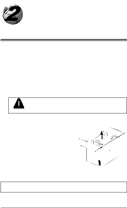
ΠCarefully open the shipping container and remove the printer.
Never rest the SV model printer “end-down” on any surface. Damage to the connectors on the bottom of
CAUTION the printer can occur.
• Remove the printer from the plastic shipping bag.
Ž Carefully remove the tape that extends over the Printhead Latch. (On SV Model printers also remove the tape that covers the interface connectors.)
þ Note: Save all packaging materials in the event that shipping the printer is ever required.
ST/SV-3210 and ST/SV-3306 |
5 |
2.0.1Inspection
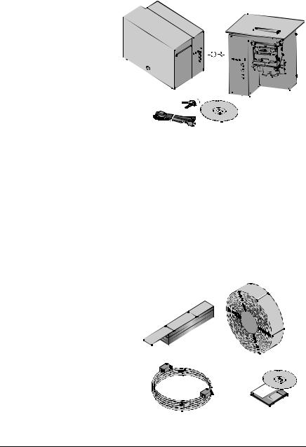
After removing and inspecting the printer, check the remaining contents of the container. In addition to this manual, the following items should be included:
Ø Ticket Printer Ø Power cord
Ø Keys (ST Models only)
Ø Accessories CD
Ø Special or additionally purchased items.
2.0.2Additional Requirements
The following items are necessary for generating printed tickets using the printer. For advice on which stock and software is best suited for your needs, contact your customer representative.
ØSerial or parallel interface cable
ØApplicable ticket stock
Ø Applicable software
6 |
ST/SV-3210 and ST/SV-3306 |
Setting up the Printer
This section details the connections, loading methods, memory module installation, and resident ticket formats of the printer.
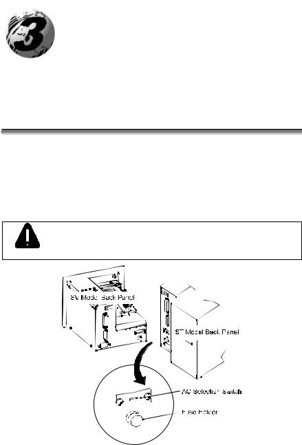
3.0AC Voltage Configuration
Depending upon the configuration of the AC Selection Switch and fuse, the printer is capable of either 115 or 230 VAC single-phase operation.
Before connecting power, check the voltage configuration: (1) locate the AC Selection Switch and Fuse Holder (containing the fuse) on the Back Panel, then (2) referencing the table below, ensure that the AC Selection Switch setting and fuse rating correspond to your AC Source Voltage.
Failure to verify the AC Selection Switch setting and fuse
rating can result in personal injury and/or printer damage.
CAUTION
AC Source Voltage |
AC Selection Switch |
Required Fuse Rating |
105 – 125 VAC |
115 VAC |
1.6 amp / 250V slow-blow |
210 – 250 VAC |
230 VAC |
0.8 amp / 250V slow-blow |
|
|
|
ST/SV-3210 and ST/SV-3306 |
7 |

3.1Interfacing the Printer
Interfacing the printer to the host computer can be made through either a parallel or a serial cable (see Appendix C for cable requirements). Communication port selection is automatic: the first port to receive data is set ‘active’ by the printer. To change an active port, cycle the power ‘Off’ and ‘On’ or perform a Warm Reset (see Section 3.6.1).
Parallel Interface Port:
The parallel interface supports Centronicsâ parallel communications.
Serial Interface Port:
The serial interface supports either RS-232 or RS-422 communications. The following menu-selectable serial port settings must be configured to match those of the host computer; see Section 4.3.
∙Baud Rate
∙Word Length (including Parity, which defaults to either of the following):
8-bit word with no parity
7-bit word with even parity
þ Note: If unable to establish communications, see Section 5 for help.
8 |
ST/SV-3210 and ST/SV-3306 |

Printer power and interface connections:
Follow these instructions to connect the printer.
Œ Turn ‘Off’ the power to the Host Computer.
•Verify that the Printer’s AC Configuration has been set; see Section 3.0.
ŽConnect the interface cable securely between the Printer and Host communication ports.
•Verify that the Power Switch is in the ‘Off’ position and connect the AC Power Cord to the AC Power Connector, then to the AC Outlet.
•Turn ‘On’ the Printer and then the Host Computer.
þ Note: Ensure the printer’s Power Switch is ‘Off’ before connecting the AC Power Cord or the interface cable; also, turn ‘Off’ the power to the host system before connecting the interface cable.
ST/SV-3210 and ST/SV-3306 |
9 |
3.2Loading Ticket Stock
Both printers feature an automatic ticket loading and positioning mechanism, although the initial loading instructions differ slightly according to model and options.
3.2.1ST Models
Œ Plug in and turn ‘On’ the printer.
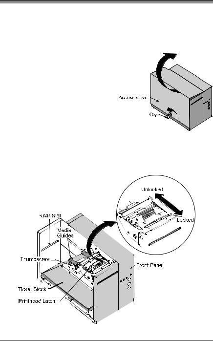
•Insert the Key and unlock the Access Cover.
Ž Raise the Access Cover (for convenience the cover may be removed by sliding it forward and then up).
•Place fanfold ticket stock (with the TOF Mark facing down; see Section 4.0) in the bottom of the printer or if using an external supply, route the stock through either the Bottom or Rear Slots.
(Continued next page)
10 |
ST/SV-3210 and ST/SV-3306 |
To use roll ticket stock, the stock must be mounted on the optional Roll Hanger, as shown. (See Section 6 for stock requirements.)
þ Note: To use an internal fanfold ticket source on a printer equipped with the Roll Hanger option, first remove the Roll Hanger by unscrewing it from the printer. Store the hanger in a safe place for future use.
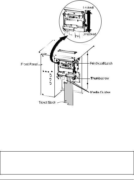
•Loosen the Thumbscrew and adjust the Media Guides to fit the width of the ticket stock: the guides should be positioned close enough to stop side-to-side ticket movement, but not so tight to cause friction or bowing of the ticket stock (see below). Tighten the Thumbscrew to secure the guides in place.
‘Slide the ticket stock through the Media Guides. The motor will start; continue sliding the tickets. The printer will grab the leading edge of the stock and complete the positioning process. Close the Access Cover.
þNotes: If automatic loading doesn’t occur:
1)Ensure that the Printhead Latch is locked.
2)Press the PAUSE button (the On-Line Indicator should be ‘Off’ now).
3)Repeatedly press the F2 button while gently pushing the stock forward until the printer grabs the ticket.
4)Press the PAUSE button (to return to the on-line mode).
If the ticket was not fed to a proper position, the TOF Sensor may need adjustment; see Section 4 for details.
ST/SV-3210 and ST/SV-3306 |
11 |
3.2.2SV Models
Œ Plug in and turn ‘On’ the printer.
•Place fanfold ticket stock in the bottom of the enclosure, bring the stock up to the Media Guides. (The TOF Mark should be facing away from the Printhead Latch; see Section 4.) Ensure that the Printhead Latch is locked.
ŽLoosen the Thumbscrew and adjust the Media Guides to fit the width of the ticket stock as described in Step 5 of Section 3.2.1.
•Slide the ticket stock through the Media Guides. The motor will start; continue feeding the tickets. The printer will grab the leading edge of the stock and complete the positioning process. If this process fails, see the note below.
þNotes: If automatic loading fails to occur, see the note at the end of
Section 3.2.1.
If the ticket did not feed to a proper position, the TOF Sensor may need adjustment; see Section 4 for details.
12 |
ST/SV-3210 and ST/SV-3306 |
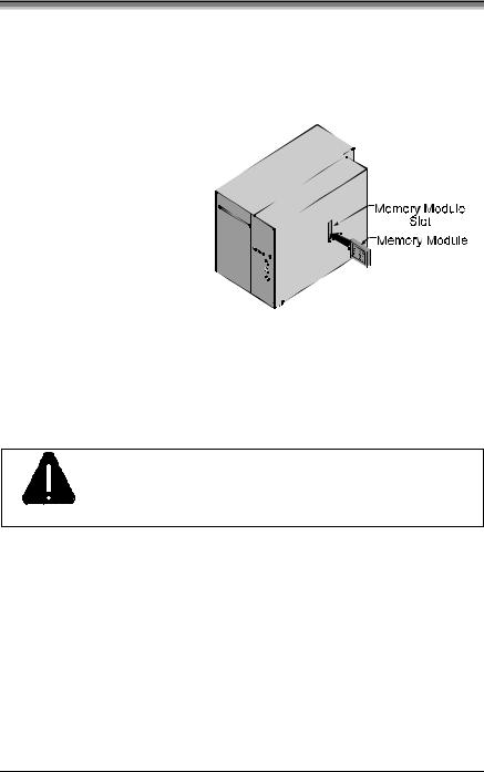
3.3Installing a Memory Module
Optional Flash Memory Modules offer convenient, non-volatile storage of formats, fonts and graphics. Refer to the DPL Programmer’s Manual (part number 88-2051-01) for programming and use details. To install a module:
Œ Turn ‘Off’ the printer.
• Place the Memory Module’s ‘write protect’ switch into the desired position (in  the ‘On’ position the module cannot be
written to).
Ž Carefully insert the Memory Module into the Memory Module Slot.
• Turn the printer ‘On’.
To avoid damage to the Memory Module or the printer, only use modules designed for this printer and always
turn the printer ‘Off’ before inserting or removing the
CAUTION module.
ST/SV-3210 and ST/SV-3306 |
13 |
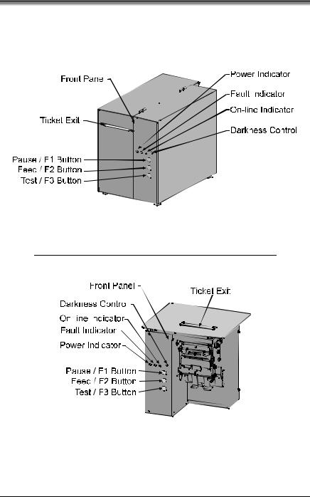
3.4Using the Front Panel
The Front Panel on both models is comprised of a ticket exit, darkness control, three indicator lights, and three dual-purpose buttons.
ST Models
SV Models
(Continued next page)
14 |
ST/SV-3210 and ST/SV-3306 |

Ticket Exit
The printed tickets are expelled from this opening.
Darkness Control
The Darkness Control will adjust the darkness of the printing on the tickets: turning the control clockwise darkens the print and turning the control counterclockwise lightens the print. This darkness function can also be controlled through software commands.
Indicators
For a brief period (approximately 20 seconds) after power-up, all three indicators will remain on while the printer performs internal diagnostics.
POWER: Turning ‘On’ the power switch lights this indicator.
FAULT: During normal operation, this indicator will flash briefly as the printer receives data from the host system; however, if a fault is detected this indicator stays on. A fault can have several different causes; see Section 5 for details.
ON-LINE: In the on-line mode, this indicator lights to denote that the printer is ready to accept data. Pressing the PAUSE button while tickets remain to print causes the indicator to flash repeatedly. This indicator remains off in the off-line mode.
Dual-Purpose Buttons
Depending upon the printer’s mode, the buttons function as follows:
On-Line Mode Button Functions (the On-Line Indicator is ‘On’)
PAUSE: Press this to temporarily stop printing (pause mode) or to enter the off-line mode.
Press this button in pause mode to resume printing from the point stopped; or, if in off-line mode press to return to the on-line mode.
FEED: Press this button to advance the ticket stock to the next print position.
TEST: This button is inactive in the on-line mode.
ST/SV-3210 and ST/SV-3306 |
15 |

Power-Up and Off-Line Mode Button Functions (the On-Line Indicator is ‘Off’)
Ø F2: |
Three functions: |
(a)Press momentarily to advance ticket stock, or to manually load ticket stock.
(b)Press and hold during power-up to print a Configuration and Test Pattern Ticket, and enter Character Dump mode.
(c)Press and hold to enter the Operational Database Modification mode; see Section 4.3 for details.
Ø F3: |
Two functions: |
(a)Press and hold to enter the Start of Print and Cut/Tear Adjustments; see Section 4.2 for details.
(b)Press momentarily to print an Internal Test Ticket; see Section 3.5.3.
ØF1 + F3: Press these simultaneously to perform a Warm Reset
and return to the on-line mode.
Ø F1 + F2: Press these simultaneously to print a Test Pattern Ticket; see Section 3.5.2.
Ø F2 + F3: Press these simultaneously to print a Configuration Ticket; see Section 3.5.1.
Ø F1 + F2 + F3: Press and hold these during power-up to reset the printer to the default settings; see Section 3.6.2.
16 |
ST/SV-3210 and ST/SV-3306 |
 Loading...