


PE Series
Operator’s Manual

CG Triumvirate is a trademark of Agfa Corporation.
CG Times, based upon Times New Roman under license from The Monotype Corporation.
SEAQ is a trademark of Datamax Barcode Products Corporation.
As an Energy Star Partner, Datamax Corporation has determined that this product meets the Energy Star guidelines for energy efficiency.
Firmware (Software) Agreement: The enclosed Firmware (Software) resident in the EPROM’s is owned by Licensor or its suppliers and is licensed for used only on a single printer in the user’s Trade or Business. The User agrees not to, and not to authorize or permit any other person or party to, duplicate or copy the EPROM’s or the information contained in the EPROM’s. The firmware (Software) is protected by applicable copyright laws and Licensor retains all rights not expressly granted. In no event will Licensor or its suppliers be liable for any damages or loss, including direct, incidental, economic, special, or consequential damages, arising out of the use or inability to use the Firmware (Software).
Information in this document is subject to change without notice and does not represent a commitment on the part of Datamax Barcode Products Corporation. No part of this manual may be reproduced or transmitted in any form or by any means, for any purpose other than the purchaser's personal use, without the expressed written permission of Datamax Corporation.
© Copyright 1998 by Datamax Corporation
All rights reserved. Printed in the United States of America.
88-2082-01 Rev. C1
Agency Compliance and Approvals
UL: UL1950 Safety of Information Technology Equipment
1. Nur für Gebrauch innerhalb eines Gebäudes geeignet.
Für 230 Volt (Europa): Benützen Sie ein Kabel, das mit "HAR" markiert ist, bestehend mindestens aus einem H05VV-F Kabel, das mindestens 0,75 Quadratmillimeter Drahtdurchmesser hat; sowie eine IEC320 Steckdose und einen für das Land geeigneten Stecker, 6A, 250 Volt.
1.This unit is intended for indoor use only.
2.Disconnect power supply cord in case of emergency.
3.When power supply cord is not provided; for proper power supply cord selection please see below:
CE: This product complies with requirements of the Low Voltage Directive 73/23/EEC and the provisions of the EMC Directive 89/336/EEC.
For 230 Volt Operation (Europe): Use a cord set, marked "HAR," consisting of a min H05VV-F cord which has a minimum 0.75 square mm diameter conductors, provided with an IEC 320 receptacle and a male plug for the country of installation rated 6A, 250V
For 120 Volt Operation (Domestic):
FCC: This device complies with FCC CFR 47 Part 15 Class A.
Note: This equipment has been tested and found to comply with the limits for a Class A digital device, pursuant to Part 15 of the FCC Rules. These limits are designed to provide reasonable protection against harmful interference when the equipment is operated in a commercial environment. This equipment generates, uses, and can radiate radio frequency energy, and if not installed and used in accordance with the instructions in this manual, it may cause harmful interference to radio communications. Operation of this equipment in a residential area is likely to cause harmful interference in which case the user will be required to correct the interference at his own expense.
Important Safety Instructions
This printer has been carefully designed to give you many years of safe, reliable performance. As with all electrical equipment, there are a few basic precautions you should take to avoid hurting yourself or damaging the printer.
Carefully read the installation and operating instructions provided with your printer.
Read and follow all warning instruction labels on the printer.
Mount the printer to a flat, firm, solid surface.
To protect your printer from overheating, make sure all openings on the printer are not blocked.
Do not place the printer on or near a heat source.
Do not use your printer near water, or spill liquid into it.
Be certain that your power source matches the rating listed on your printer. If you are unsure, check with your dealer or with your local power company.
Do not place the power cord where it will be walked on. If the power cord becomes damaged or frayed replace it immediately.
Do not insert anything into the ventilation slots or openings on the printer.
Only qualified, trained service technicians should attempt to repair your printer.
Contents
Printer Overview
1.0 |
Introduction ........................................................................ |
1 |
|
1.1 |
About This Printer............................................................... |
2 |
|
|
1.1.1 |
Standard Features.................................................... |
2 |
|
1.1.2 |
Optional Features.................................................... |
3 |
Getting Started
2.0 |
Before Using This Printer..................................................... |
5 |
2.1 |
General Overview............................................................... |
7 |
Setting Up the Printer
3.0 |
Introduction ........................................................................ |
9 |
3.1 |
Connecting the Printer.......................................................... |
9 |
3.2 |
Loading Media................................................................... |
10 |
3.3 |
Loading Ribbon (Thermal Transfer)..................................... |
13 |
3.4 |
Ribbon Removal ................................................................ |
15 |
3.5 |
Installing a FLASH Cartridge .............................................. |
17 |
3.6 |
Printing a Configuration Label............................................. |
19 |
3.7 |
Configuration Label Explanation.......................................... |
22 |
3.8 |
Test Pattern Label .............................................................. |
23 |
3.9 |
Applicator Connection........................................................ |
24 |
3.10 |
Options Port....................................................................... |
26 |
i
Using Your Printer
4.0 |
Using the Printer’s Front Panel ............................................ |
28 |
|
4.1 |
Accessing the Menu Tree ................................................... |
30 |
|
|
4.1.1 |
Basic Functions ........................................................ |
30 |
|
4.1.2 |
Advanced Setup ....................................................... |
32 |
Printer Adjustments
5.0 |
Introduction ....................................................................... |
42 |
5.1 |
Media Sensor Adjustment................................................... |
42 |
5.2 |
Media Width Adjustment.................................................... |
43 |
5.3 |
Label Start of Print ............................................................. |
44 |
5.4 |
Label Presentation.............................................................. |
44 |
5.5 |
Setting Start of Print and Peel Position................................. |
45 |
5.6 |
Controlling Print Quality..................................................... |
46 |
Maintenance
6.0 |
Introduction ....................................................................... |
48 |
6.1 |
Cleaning Schedule.............................................................. |
49 |
6.2 |
Cleaning the Printhead ........................................................ |
50 |
6.3 |
Cleaning the Platen Roller................................................... |
51 |
Troubleshooting
7.0 |
Introduction ....................................................................... |
52 |
7.1 |
Troubleshooting Tips ......................................................... |
52 |
7.2 |
Error Messages .................................................................. |
56 |
7.3 |
Character Dump Mode ....................................................... |
61 |
ii
Appendices
Appendix A |
|
ASCII Control Chart.................................................................. |
A-1 |
Appendix B |
|
Available Fonts and Barcodes.................................................... |
B-1 |
Human-Readable Fonts.............................................................. |
B-2 |
Barcode Fonts........................................................................... |
B-5 |
Appendix C |
|
Cable Listing ............................................................................ |
C-1 |
Appendix D |
|
Applicator Port Test Box........................................................... |
D-1 |
Appendix E |
|
Error Codes .............................................................................. |
E-1 |
Appendix F |
|
Printer Specifications................................................................. |
F-1 |
Printer Dimensions .................................................................... |
F-4 |
Media Specifications................................................................. |
F-5 |
Media and Ribbon Basics .......................................................... |
F-6 |
Appendix G |
|
Menu Tree................................................................................ |
G-1 |
Appendix H |
|
Warranty Information................................................................. |
H-1 |
iii
Printer Overview
1.0 Introduction
The PE Series, hereafter referred to as the printer, is a high quality, high volume, extremely durable print engine, designed exclusively for use with label applicator systems.
Available in a wide range of configurations, the printer offers both direct thermal or thermal transfer printing and comes equipped with many popular bar codes, nine resident fonts, a smooth bit-mapped font (CG Triumvirate ) and a scaleable font (CG Triumvirate Bold Condensed ).
This manual provides all the information necessary to operate the printer. To print labels or tags, simply refer to the instructions included with the software you have chosen to create your labels.
Right-Hand Model |
Left-Hand Model |
Figure 1-1 PE Series Print Engines
PE Series Operator’s Manual |
1 |

1.1About This Printer
This printer offers the following standard and optional features:
1.1.1 Standard Features
Advanced Technology
This printer utilizes the Intel I960 32 Bit RISC Microprocessor and Datamax application specific integrated circuitry (ASIC). The ASIC design includes highly integrated components, along
with the Datamax proprietary SEAQ Circuit, which maintains printhead thermal control to provide consistent print quality.
Interfaces
This printer is equipped with two serial data communication interfaces that support RS-232, RS-422, or RS-485 and one Centronics® parallel data communication interface. The printer is easily connected to any host using one of the cable configurations listed in Appendix C.
Control Panel
The detachable/rotatable printer control panel has one liquid crystal display (LCD), three LEDs, three primary operational keys and six additional menu keys.
2 |
PE Series Operator’s Manual |
1.1.2 Optional Features
300 DPI
This factory installed option provides a printhead resolution of 300 dots per inch with a 4.16 inch print width and 1MB DRAM.
Left-Hand
Left-hand label output model for system configuration flexibility.
Memory Expansion
On-board memory DRAM expansion to 4 MB total for expanded print length, temporary image storage and scaleable font character cache.
FLASH Cartridge
A removable module used for permanent storage of custom fonts, format and graphics. Available in 256K, 512K, 1 MB and
2 MB sizes.
Ribbon Saver
This factory installed option eliminates ribbon waste when feeding past non-printed label areas.
PE Series Operator’s Manual |
3 |
4 |
PE Series Operator’s Manual |

Getting Started
2.0Before Using This Printer
Unpacking the Printer
The printer was carefully packaged to avoid any damage during transit. Before opening, closely inspect the box for damages. In the event of shipping damage, contact the carrier immediately regarding it’s nature and extent.
In order to operate the printer you will need to remove the packaging materials that are placed inside the printer for shipment. Complete the following steps before connecting power. It may be helpful to refer to Figure 2-2 when removing the packing material.
n Remove the printer from the box.
o Remove the printer from the plastic bag.
p Remove the tape that extends over the printhead assembly.
q Remove the piece of foam between the printhead and platen.
rRemove the tape that covers the J-Hook on the Ribbon Take-Up Hub.
;Note: Save all packaging materials in the event that shipping the printer is ever required.
PE Series Operator’s Manual |
5 |
Inspecting the Printer
After removing the printer from the box, check the remaining contents of the package. In addition to this manual, the following items should be present:
label printer installation guide sample print labels
power cord
any special or additional items purchased
Additional Requirements
The following items are necessary for generating labels with your printer. Contact your dealer or a technical support representative for advice on media and software.
Serial or parallel interface cable (see Appendix C).
Applicable media (see Appendix F).
Applicable software
6 |
PE Series Operator’s Manual |
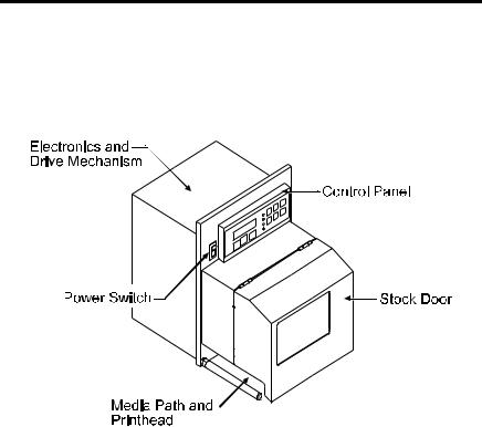
2.1General Overview
The following illustrations show the major components of your printer. It may be helpful to refer back to this section for the names and locations of the printer’s various parts.
Figure 2-1 Right-Hand Model, External Front View
PE Series Operator’s Manual |
7 |

Figure 2-2 Right-hand Model, Interior Front View
Figure 2-3 Right-Hand Model, Media Path
8 |
PE Series Operator’s Manual |
Setting Up the Printer
3.0Introduction
This chapter explains how to connect the printer to the host, load media and print a configuration label.
3.1Connecting the Printer
; Note: Ensure that the printer’s power switch is ‘off’ when connecting the AC power cord or any interface cable.
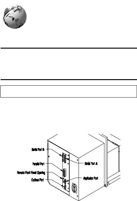
Connect the AC power cord to the back of the printer before plugging into a properly grounded outlet. The printer can be connected to the host computer with a parallel or serial cable, (see Appendix C). The applicator connections should also be made at this time. The figure below shows the position of the interface ports.
Figure 3-1 Connecting the Printer
PE Series Operator’s Manual |
9 |
3.2Loading Media
This section explains the loading of media.
nMove the Head-Lift Lever ‘up’ to raise the printhead, as shown in Figure 3-2.
Figure 3-2 Head-Lift Lever
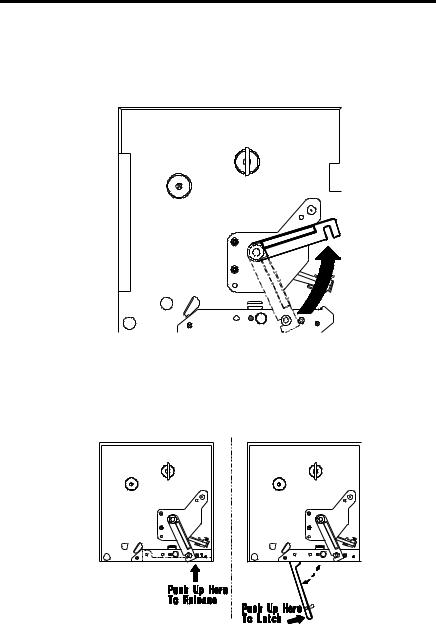
oPush ‘up’ on the hinged Drive Plate at the point shown in Figure 3-3. This will release the plate, allowing it to swing down.
Figure 3-3 Opening and Closing the Drive Plate
10 |
PE Series Operator’s Manual |
pPeel the first 12 inches of label material from the liner and discard.
;Note: If you wish to leave the label attached to the liner do not thread the media through the Drive Plate.
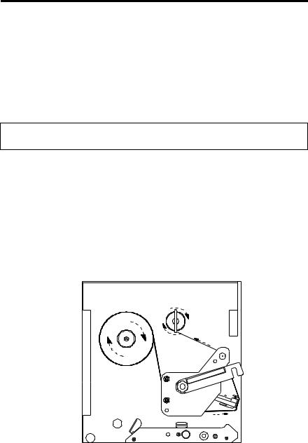
Figure 3-4 Media Loading
qFeed the liner as shown in Figure 3-4. Be sure that the liner passes through the “fingers” of the Label Edge Sensor. Continue feeding the liner, bringing it under the Drive Plate Hinge Pin (see Figure 3-5). Pull through removing any slack.
;Note: When using narrow media, it may be necessary to adjust the position of the Label Edge Sensor to ensure detection. This is done by turning the Edge Sensor Adjustment Knob (see Figure 2-3).
PE Series Operator’s Manual |
11 |
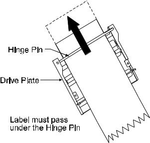
Figure 3-5 Media Loading (detail)
rTo close, raise the Drive Plate back up, until the plate snaps into place. See Figure 3.3.
sLower the Head-Lift Lever until the printhead is locked in the down position.
12 |
PE Series Operator’s Manual |
3.3Loading Ribbon (Thermal Transfer)
The printer can use two methods to create an image on the media. The first method, called direct thermal, uses specially treated label stock containing dyes that turn black with heat and pressure.
The second method is thermal transfer, which involves the transfer of ink from a ribbon substrate onto the media with heat and pressure. The ink is transferred to the label stock as it passes between the printhead and the platen roller. To use this method, set the printer to “transfer” before printing.
; Note: Ribbon should never be used with direct thermal stock. Using this stock with a ribbon will result in poor quality print.
Complete the following steps to load ribbon:
n Unlatch and raise the printhead.
oSlide the ribbon roll onto the Ribbon Supply Hub with the leader coming over the top of the roll. Ensure that the ribbon roll is pushed back fully against the flange at the base of the Ribbon Supply Hub.
p Thread the ribbon along the path as shown in Figure 3-6.
Figure 3-6 Ribbon Loading Path
PE Series Operator’s Manual |
13 |
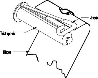
qRemove the J-Hook from the Ribbon Take-up Hub, ( as a convenient option you may use an empty ribbon core to rewind the spent ribbon, if using this method do not reinstall the J-Hook).
rWhile holding the Ribbon Take-up Hub, rotate the J-Hook to unlatch it.
sRaise the J-Hook away from the hub and place the end of the ribbon over the take-up hub.
Figure 3-7 J-Hook
tSlide the J-Hook back into place as shown in Figure 3-7. While holding the Ribbon Take-up Hub, rotate the J-Hook until it latches. Turn the Ribbon Take-up Hub several times to secure the ribbon.
uLower the Head Lift Lever until the printhead is locked in the down position.
14 |
PE Series Operator’s Manual |
3.4Ribbon Removal
Removal of a Partially Used Roll of Ribbon
Complete the following steps to remove and save a ribbon:
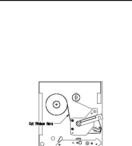
n Cut the ribbon at the point shown in Figure 3-8.
oTurn the Ribbon Take-up Hub until the end of the ribbon has cleared the printhead area.
pGrasp the roll of used ribbon and slide the used ribbon straight off the Ribbon Take-up Hub. Discard the used ribbon.
qGrasp the roll of unused ribbon, pull and slide the unused ribbon from the Ribbon Supply Hub, storing it for future use.
Figure 3-8 Ribbon Cutting Point
PE Series Operator’s Manual |
15 |
Removal of a Completely Used Ribbon
Complete the following steps to remove a completely used ribbon:
n Unlatch and raise the printhead.
oRotate the Ribbon Take-up Hub, winding it until the ribbon clears the media path.
p Rotate the J-Hook, unlatch and remove.
qGrasp the roll of used ribbon and pull it straight off of the Ribbon Take-up Hub and discard.
|
r Pull the empty ribbon supply core from the Ribbon |
Supply |
Hub. Save the core for later use on the Ribbon |
Take-Up |
Hub or discard. |
16 |
PE Series Operator’s Manual |
3.5Installing a FLASH Cartridge
FLASH cartridges provide the same features as DRAM, with the added benefit of providing permanent storage for custom fonts, label formats and images. FLASH memory is essentially a non-volatile, electronically erasable PROM. A write protect switch on the cartridge is used to safeguard stored data against accidental erasure.
To install a memory cartridge:
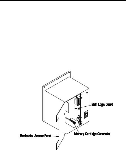
n Turn ‘off’ and unplug the printer.
oRemove the two screws securing the Electronics Access Panel and open to reveal the connector, see figure below.
Figure 3-9 FLASH Cartridge Connector Location
PE Series Operator’s Manual |
17 |
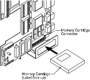
pHolding the FLASH Cartridge with the label facing up, insert it into the connector, see Figure 3-10. Push firmly, but do not force it, doing so could damage the cartridge and socket.
Figure 3-10 Inserting the Memory Cartridge
qClose the Panel and secure it with the screws. Plug in and turn ‘on’ the printer. The printer will refer to the FLASH Cartridge as Module B.
18 |
PE Series Operator’s Manual |

3.6Printing a Configuration Label
Before beginning, load the printer with 4” wide media or configure the Label Width Adjustment in the Advanced Setup Menu to meet your label width, (for thermal transfer, also use a matching ribbon.
For direct thermal labels, be sure that “Direct” has been selected in the "Print Method"). See Section 4 for more setup information. To print a Configuration Label:
n Turn the printer ‘Off”.
oPress and hold the ‘Feed’ button while turning the printer ‘On’.
p Release the ‘Feed’ button after the printer display reads
‘DYNAMIC RAM DIAGNOSTICS’...
After a brief period, the labels will be printed. (If the labels are not printed, see Section 7). Referring to Figure 3-11, the Configuration Label contains two types of information. The first type is printer setup data. The second is a pattern, testing the print circuitry. In addition, a special connector can be used to test communications, see Section 4 on Serial Loopback for more details.
; Note: After running the Configuration Label, the printer will enter Character Dump Mode and must be reset in order to run a label application. To reset, power the printer ‘Off’ and then ‘On’. For Character Dump Mode information see Section 7.
PE Series Operator’s Manual |
19 |

COMMUNICATION OPTIONS |
|
|||
INPUT PORT _ _ _ _ _ |
PORT A |
|||
BAUDRATE |
_ _ _ _ |
9600 |
|
|
PARITY _ _ _ _ _ _ _ |
NONE |
|||
WORD LENGTH _ _ _ |
8 BIT |
|||
STOP BITS |
_ _ _ _ _ _ _ |
1 |
|
|
PROTOCOL |
|
|
BOTH |
|
CONTROL CODES |
STANDARD |
|||
OPERATION |
|
|
|
|
PAUSE MODE |
_ _ _ _ _ |
DISABLE |
||
FEEEDBACK MODE _ _ |
DISABLE |
|||
TEST MODE |
_ _ _ _ _ |
DISABLE |
||
LABEL OPTIONS |
|
|
|
|
HEAT SETTING |
_ _ _ _ _ _ _ _ 10 |
|||
PRINT SPEED |
|
_ _ _ _ _ _ _ _ _ 6.0 IPS |
||
SLEW SPEED _ _ _ _ _ _ _ _ _ _ 8.0 IPS |
||||
BACKFEED SPEED _ _ _ _ _ _ _ 5.0 IPS |
||||
ROW ADJUST _ _ _ _ _ _ _ _ _ _ |
0 in |
|||
COLUMN ADJUST _ _ _ _ _ _ _ |
0 in |
|||
LABEL WIDTH _ _ _ _ _ _ _ _ _ |
410 in |
|||
CONT. LABEL LEN _ _ _ _ _ _ _ |
0 in |
|||
PRESENT DIST |
_ _ _ _ _ _ _ _ |
320 in |
||
PE INFORMATION |
|
|
||
LOW RIBBON INCHES _ _ _ _ |
20 |
|||
PRINTER MODEL _ _ _ _ _ _ _ |
RIGHT |
|||
TUE FEBRUARY 17 , 1998 |
14:07 048 |
|||
DATABASE INFORMATION |
|
|
||
SECURITY _ _ _ _ _ _ _ _ _ _ NONE |
||||
VER: HA - 02 . 30 02/07/98 |
|
|
||
ROM CHECKSUMS |
|
|
||
U39 47-2081-03K |
|
|
||
U37 47-2080-03K |
|
|
||
U38 47-2166-01B |
|
|
||
U40 47-2067-01B |
|
|
||
SYSTEM RAM CHECKS _ _ _ _ _ |
GOOD |
SYSTEM RAM SIZE _ _ _ _ _ _ _ _ 512 KBYTES |
|
SERIAL LOOPBACK CHECK_ _ _ _ _ |
GOOD* |
CTS & DTR LOOPBACK CHECK_ _ _ _ _ |
GOOD* |
BASIC FUNCTIONS |
|
|
|
|
|
PRINT METHOD _ _ _ _ _ _ _ |
|
TRANSFER |
|||
SELECT TOF |
_ _ _ _ _ _ _ _ |
GAP |
|
||
DARKNESS _ _ _ _ _ _ _ _ _ _ |
|
33 |
|
||
CUTTER _ _ _ _ _ _ _ _ _ _ _ _ |
|
DISABLE |
|||
RIBBON SAVER _ _ _ _ _ _ _ DISABLE |
|||||
INTERNAL BATCH _ _ _ _ _ |
|
DISABLE |
|||
CONVERSION |
_ _ _ _ _ _ _ _ |
DECIMAL |
|||
TOP ADJUST _ _ _ _ _ _ _ _ _ |
|
64 |
|
||
COMPATABILITY |
|
|
|
|
|
DPI EMULATION |
|
|
203 |
|
|
OFFSET BIAS |
|
|
|
220 |
|
HARDWARE |
|
|
|
|
|
BATTERY LEVEL _ _ _ _ _ _ _ |
GOOD |
|
|||
THERMISTOR ADC _ _ _ _ _ _ |
|
65 |
|
||
REFLECTIVE ADC _ _ _ _ _ _ _ |
|
0 |
|
||
TRANSMISSIVE ADC _ _ _ _ _ |
|
165 |
|
||
PAPEROUT ADC _ _ _ _ _ _ _ _ |
|
0 |
|
||
INSTALLED OPTIONS |
|
|
|
|
|
RIBBON SAVER _ _ _ _ _ _ _ _ |
NO |
|
|||
CUTTER _ _ _ _ _ _ _ _ _ _ _ _ NO |
|
||||
PE SIGNALLING |
|
|
|
|
|
PE APPLY HW |
_ _ _ _ _ _ _ _ _ |
|
DISABLE |
||
PE EXT SIGNAL _ _ _ _ _ _ _ _ |
|
LOW PULSE |
|||
RIBBON LOW ACTIVE |
_ _ _ _ |
LOW |
|||
BACKFEED CONTROL |
_ _ _ _ |
20ms |
|||
COUNTER INFORMATION |
|
|
|
||
ABSOLUTE VALUES |
02-10-98 |
|
|||
LENGTH _ _ _ _ _ _ _ |
11644 INCHES |
|
|||
MEMORY CONFIGURATION |
|
|
|
||
INTERNAL MODULE _ _ _ _ _ _ _ _ |
32 |
||||
SCALABLE FONTS _ _ _ _ _ _ _ _ _ |
0 |
||||
SYMBOL SET _ _ _ _ _ _ PC-850 MODIFIED
* ONLY PRESENT WITH SPECIAL TEST PLUG
Figure 3-11 Configuration Label
; Note: Your Configuration Label may vary due to the printer configuration or the printer firmware version.
20 |
PE Series Operator’s Manual |
 Loading...