


E-4203 / E-4204 / E-4304
w/USB
Operator’s Manual
Copyright Information:
CG Triumvirate is a trademark of Agfa Corporation.
CG Times based upon Times New Roman under license from the Monotype Corporation.
Windows is a registered trademark of the Microsoft Corporation.
All other brand and product names are trademarks, service marks, registered trademarks, or registered service marks of their respective companies.
Firmware (Software) Agreement
The enclosed Firmware (Software) resident in the Printer is owned by Licensor or its suppliers and is licensed for used only on a single printer in the user’s Trade or Business. The User agrees not to, and not to authorize or permit any other person or party to, duplicate or copy the Firmware or the information contained in the non-volatile or programmable memory. The firmware (Software) is protected by applicable copyright laws and Licensor retains all rights not expressly granted. In no event will Licensor or its suppliers be liable for any damages or loss, including direct, incidental, economic, special, or consequential damages, arising out of the use or inability to use the Firmware (Software).
Information in this document is subject to change without notice and does not represent a commitment on the part of Datamax Barcode Products Corporation. No part of this manual may be reproduced or transmitted in any form or by any means, for any purpose other than the purchaser's personal use, without the expressed written permission of Datamax Corporation.
All rights reserved. Printed in the United States of America.
© Copyright 2002 by Datamax Corporation
Part Number: 88-2304-01
Revision: A

Agency Compliance and Approvals:
UL1950 Information Technology Equipment
C22.2 No. 950-M93
C US
Listed
EN60950
For 230 Volt Operation (Europe): Use a cord set, marked "HAR," consisting of a min H05VV-F cord which has a minimum 0.75 square mm diameter conductors, provided with an IEC 320 receptacle and a male plug for the country of installation rated 6A, 250V
Für 230 Volt (Europa): Benützen Sie ein Kabel, das mit "HAR" markiert ist, bestehend mindestens aus einem H05VV-F Kabel, das mindestens 0,75 Quadratmillimeter Drahtdurchmesser hat; sowie eine IEC320 Steckdose und einen für das Land geeigneten Stecker, 6A, 250 Volt.
As an Energy Star Partner, the manufacturer has determined that this product meets the Energy Star guidelines for energy efficiency.
The manufacturer declares under sole responsibility that this product conforms to the following standards or other normative documents:
EMC: |
EN 55022 |
(1993) Class A |
|
EN 50024 |
(1998) |
Safety: This product complies with the requirements of EN 60950 /A11:1997
Gost-R
FCC: This device complies with FCC CFR 47 Part 15 Class A.
; Note: This equipment has been tested and found to comply with the limits for a Class A digital device, pursuant to Part 15 of the FCC Rules. These limits are designed to provide reasonable protection against harmful interference when the equipment is operated in a commercial environment. This equipment generates, uses, and can radiate radio frequency energy, and if not installed and used in accordance with the instructions in this manual, it may cause harmful interference to radio communications. Operation of this equipment in a residential area is likely to cause harmful interference in which case the user will be required to correct the interference at his own expense.
Important Safety Instructions
This printer has been carefully designed to provide many years of safe, reliable performance. As with all electrical equipment, there are a few basic precautions you should take to avoid hurting yourself or damaging the printer:
Carefully read the installation and operating instructions provided with your printer.
Read and follow all warning instruction labels on the printer.
Place the printer on a flat, firm, solid surface.
To protect your printer from overheating, make sure all openings on the printer are not blocked.
Do not place the printer on or near a heat source.
Do not use your printer near water, or spill liquid into it.
Be certain that your power source matches the rating listed on your printer. If you are unsure, check with your dealer or with your local power company.
Do not place the power cord where it will be walked on. If the power cord becomes damaged or frayed replace it immediately.
Do not insert anything into the ventilation slots or openings on the printer.
Only qualified, trained service technicians should attempt to repair your printer.

Printer Overview |
|
|
1.0 |
Introduction......................................................... |
1 |
1.1 |
About this Printer ................................................ |
2 |
|
1.1.1 Standard Features ..................................... |
2 |
|
1.1.2 Optional Features ...................................... |
3 |
Getting Started |
|
|
2.0 |
Before using the Printer....................................... |
5 |
Setting Up the Printer |
|
|
3.0 |
Introduction......................................................... |
7 |
3.1 |
Connecting the Printer ........................................ |
7 |
|
3.1.1 Power Connection ...................................... |
7 |
|
3.1.2 Interface Connection .................................. |
8 |
|
3.1.3 Interface Cables ......................................... |
8 |
3.2 |
Adjusting the Media Sensor................................. |
9 |
3.3 |
Loading Media..................................................... |
12 |
|
3.3.1 Loading Media for Peel Configuration ......... |
14 |
3.4 |
Loading Ribbon................................................... |
15 |
3.5 |
Flash Memory Expansion .................................... |
17 |
Using the Front Panel |
|
|
4.0 |
Introduction......................................................... |
19 |
4.1 |
Lights.................................................................. |
19 |
4.2 |
Buttons ............................................................... |
20 |
4.3 |
Normal Mode - Button Functions ......................... |
20 |
4.4 |
Printer Setup Mode - Button Functions................ |
21 |
|
4.4.1 Printer Setup Menu List.............................. |
22 |
|
4.4.2 Menu Items and Values.............................. |
23 |
|
4.4.3 Step by Step Modification........................... |
26 |
4.5 |
Label Alignment .................................................. |
28 |
|
4.5.1 Label Alignment = YES .............................. |
28 |
|
4.5.2 Label Alignment = AUTO............................ |
29 |
|
i |
|

|
4.5.3 Label Alignment = NO ................................ |
29 |
|
4.5.4 Label Alignment Troubleshooting ............... |
30 |
4.6 |
Calibration Mode – Button Functions ................... |
34 |
|
4.6.1 Auto Media Sensor Calibration.................... |
35 |
|
4.6.2 Manual Media Sensor Calibration ............... |
36 |
4.7 |
Internal Labels .................................................... |
37 |
|
4.7.1 Database Configuration/Dot Check Labels.. 37 |
|
|
4.7.2 Test Label .................................................. |
39 |
|
4.7.3 Hex Dump Label ........................................ |
39 |
Maintenance and Adjustments |
|
|
5.0 |
Introduction......................................................... |
41 |
5.1 |
Cleaning the Printhead........................................ |
42 |
5.2 |
Media Width Adjustment ..................................... |
43 |
5.3 |
Ribbon Width Adjustment.................................... |
44 |
5.4 |
Fine Printhead Adjustment .................................. |
45 |
5.5 |
Printhead Replacement....................................... |
46 |
5.6 |
Darkness Adjustment .......................................... |
47 |
5.7 |
Resetting to the Factory Defaults......................... |
47 |
5.8 |
Downloading Firmware and Fonts ....................... |
47 |
Troubleshooting |
|
|
6.0 |
Introduction......................................................... |
49 |
6.1 |
Troubleshooting Tips .......................................... |
49 |
Specifications |
|
|
Mechanical ................................................................ |
53 |
|
Printing...................................................................... |
53 |
|
Media/Ribbon ............................................................ |
54 |
|
Communications........................................................ |
54 |
|
Fonts......................................................................... |
54 |
|
Embedded Bar Codes ............................................... |
54 |
|
Approved Media......................................................... |
55 |
|
ii

Appendix A |
|
ASCII Control Code Chart .......................................... |
57 |
Appendix B |
|
Embedded Fonts and Barcodes................................. |
59 |
Appendix C |
|
Warranty Information ................................................. |
69 |
Glossary................................................................... |
73 |
Index........................................................................... |
79 |
iii

iv
1.0Introduction
The E-4203, E-4204, and E-4304 (hereafter referred to as ‘the printer’) are user-friendly printing devices that blend quality and durability into an affordable package. The printer, available in direct and optional thermal transfer configurations, uses a unique front panel design to simplify operation, while its RS232 serial and parallel interfaces allow easy connection to your host system.
Direct Thermal Model |
Thermal Transfer Model |
This manual provides all the information necessary to operate the printer.
To print labels or tags simply refer to the instructions included with the software you have chosen to create the labels. A Windows printer driver can be found on our website (www.datamaxcorp.com) or on the Datamax Accessories CD-ROM. If you wish to write a custom program, a copy of the E-Class Programmer’s Manual (part number 88-2265-01) can also be found on the Accessories CD-ROM.
E-4203/E-4204/E-4304 |
1 |

1.1About this Printer
This printer offers the following standard and optional features:
1.1.1 Standard Features
Printing
¾Direct Thermal Printing
¾On Demand and Batch Printing
¾203 or 300 DPI Printhead (model dependant)
¾AGFA Scalable Font Engine
Memory
¾1 MB FLASH Memory
¾2 MB DRAM Memory
Interfaces
¾RS-232 serial interface
¾Centronics parallel interface
¾USB Port
Operational
¾Simple Media Loading
¾Media Tearbar
¾Fan-fold media compatible from rear of printer
¾1inch (25mm) internal media supply core
2 |
E-4203/E-4204/E-4304 |

1.1.2 Optional Features
Adjustable Media Sensor
The Adjustable Media Sensor allows the printer to detect the position of the gap, notch, or reflective mark at many locations across the media.
External Media Supply Stand
The External Media Supply Stand allows the printer to use large media supply rolls, up to 8-inches in diameter and wound on one to three inch cores. (Not available for the E-4304.)
FLASH Memory Expansion
The FLASH Expansion cartridges are used for permanent storage of custom fonts, formats and graphics. The FLASH memory cartridges cannot be used in conjunction with the ILPC option.
Heavy Duty Power Supply
The Heavy Duty Power Supply is available for use in high demand applications. This power supply will also increase the E-4203’s print speed capability to 4 IPS.
ILPC
The International Language Print Capability consisting of one of the following:
¾CG-Times (western European) Scalable font
¾Kanji Gothic B Scalable font
¾Simplified Chinese GB Scalable font
Media Cutter
The Media Cutter automatically cuts your tag or label media after printing. This device mounts easily onto the front of the printer.
E-4203/E-4204/E-4304 |
3 |

Present Sensor
The Present Sensor allows the printer to be configured for “one up” printing. With the sensor installed, the printer will not print the next label until the previously printed label has been removed from the printer.
Thermal Transfer
The Thermal Transfer option allows the printer to use ribbon. The ink/wax from the ribbon transfers to the media to create an image with exceptional clarity and scanability.
4 |
E-4203/E-4204/E-4304 |
2.0Before Using the Printer
Removing the Packaging
Inspect the shipping container(s) for damage; if damage is evident notify the shipping company to report the nature and extent of the damage.
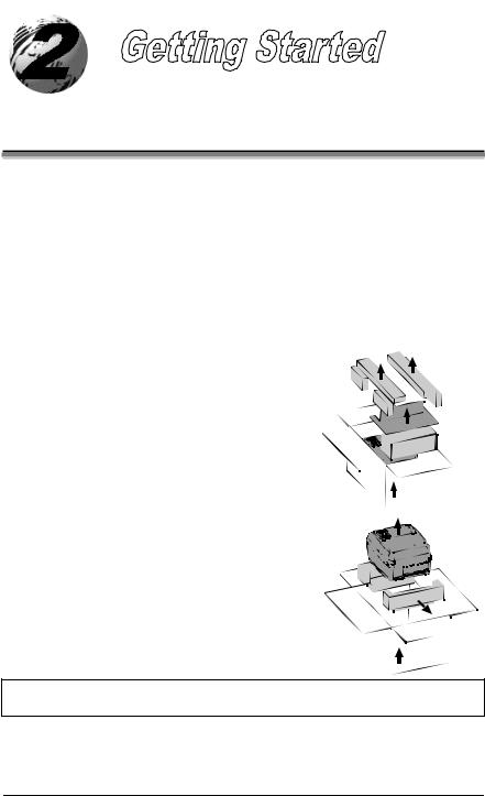
The printer is carefully packaged to avoid any damage during transit. In order to operate the printer you will need to remove the packaging materials (i.e., tape and foam) that were placed in the printer for shipment. Complete the following steps prior to connecting power or attempting to load media.
¾ Ensure that the arrow on the box is pointing up, and then open the box.
¾ Remove the packing foam, cardboard divider, and power supply box.
¾ Lift the printer from the box and remove the packing foam.
¾ Remove the printer from the plastic bag.
; Note: It is a good idea to save all packaging materials in the event that shipping the printer is ever required.
E-4203/E-4204/E-4304 |
5 |
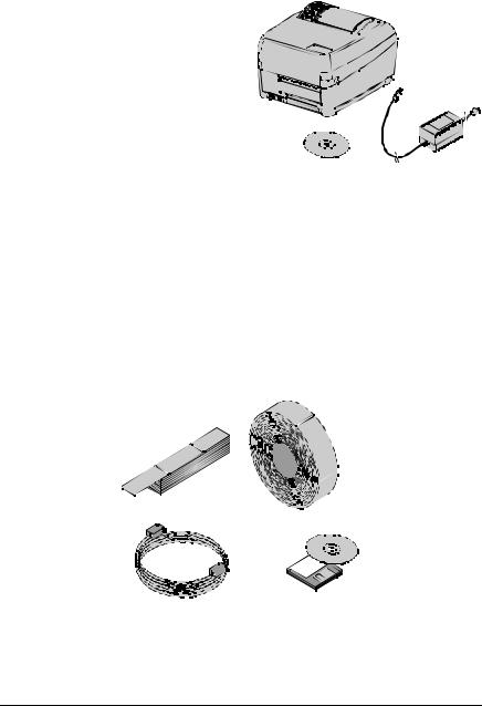
Inspecting the Printer
After removing the printer from the packaging material, check the contents. The following items should be included:
¾ Printer
¾ Power supply
¾ Accessories CD-ROM
¾ Any special or additionally purchased items.
Additional Requirements
The following items are necessary for generating labels from your printer. Contact your customer support representative for advice on which media and software may best be suited for your application.
¾USB, Serial, or parallel cable
¾Applicable media
¾Applicable software
6 |
E-4203/E-4204/E-4304 |
3.0Introduction
This chapter explains how to connect your printer, load media (and ribbon, if equipped for thermal transfer), and print a configuration label.
3.1 Connecting the Printer
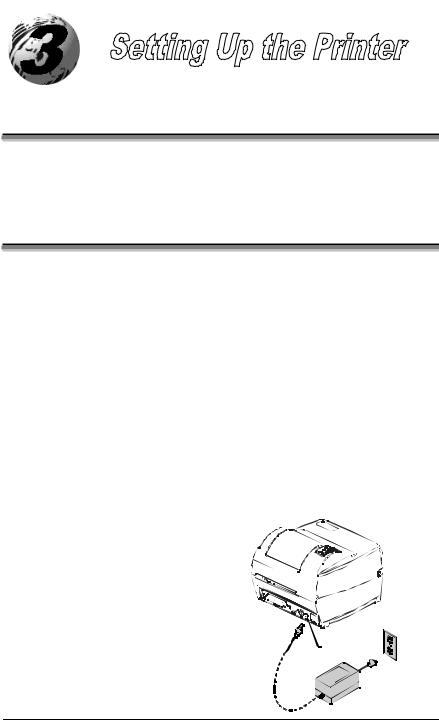
3.1.1 Power Connection
The printer is powered by an external power supply that connects as shown below. Several different power supplies are available depending upon the printer model.
Model |
Auto-Ranging |
Power Supply Part Number* |
|
E-4203 |
No |
110V: 50-2024-01 |
|
220V: 50-2034-01 |
|||
|
|
||
E-4203 with the 4 IPS option |
Yes |
50-2050-01 |
|
E-4204 |
Yes |
50-2050-01 |
|
E-4304 |
Yes |
50-2050-01 |
*An optional Heavy Duty Power Supply (50-2049-01), designed for use in high-demand applications, is available for use with all models; see Specifications for details.
Ensure that the power supply shipped with your printer is compatible with your electrical service.
Power
Connection
E-4203/E-4204/E-4304 |
7 |
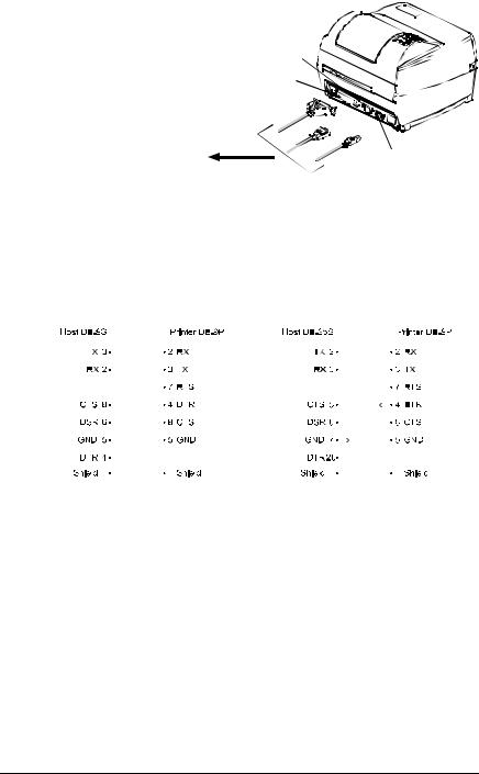
3.1.2 Interface Connection
The printer can be connected to the host via a USB, serial or parallel cable.
Serial
Connection
Parallel
Connection
-OR-
 To Host

 -OR-
-OR-
USB
Connection
3.1.3 Interface Cables
Choose one connection method that will best serve your purpose:
yTo connect the printer to the host’s serial (RS-232C) interface use an acceptable cable configuration, as shown below (contact your reseller for ordering information).
|
|
|
|
|
|
|
|
|
|
|
|
|
|
|
|
|
|
|
|
|
|
|
|
|
|
|
|
|
|
|
|
|
|
|
|
|
|
|
|
|
|
|
|
|
|
|
|
|
|
|
|
|
|
|
|
|
|
|
|
|
|
|
|
|
|
|
|
|
|
|
|
|
|
|
|
|
|
|
|
|
|
|
|
|
|
|
|
|
|
|
|
|
|
|
|
|
|
|
|
|
|
|
|
|
|
|
|
|
|
|
|
|
|
|
|
|
|
|
|
|
|
|
|
|
|
|
|
|
|
|
|
|
|
|
|
|
|
|
|
|
|
|
Part # 32-2300-01 |
Part # 32-2301-01 |
|
||||||||||
yTo connect the printer to the host’s parallel interface use a Centronics parallel cable.
yTo connect the printer to the host’s USB interface use a standard USB cable.
Note that the printer has a unique feature: When connected via more than one interface, it will automatically connect to the first port (serial, parallel, or USB) that transmits valid data. After this connection has been made, the printer’s power must be cycled ‘Off’ and ‘On’ to change the interface connection.
8 |
E-4203/E-4204/E-4304 |

3.2Adjusting the Media Sensor
The printer is available with a Fixed-Position Media Sensor or an Adjustable Media Sensor. To identify the type of sensor in your printer:
1.Open the cover.
2.Push down the Printhead Latch and raise the Printhead Carrier Assembly.
The Fixed-Position Media Sensor, shown below, cannot be moved. If your printer has this type of sensor, proceed to ‘Loading Media’ (Section 3.3).
Printhead
Carrier Assembly


 Fixed-Position Media Sensor
Printhead Latch
The Adjustable Media Sensor (AMS), shown below, may need to be positioned.
Printhead
Carrier Assembly
Printhead Latch |
Adjustable Media Sensor |
|
E-4203/E-4204/E-4304 |
9 |
The position of the AMS is important for the proper detection of media and the label top of form (TOF). The table below indicates suggested sensor positions for various media types.
Adjustable Media Sensor Position
|
Media Type |
Suggested Sensor Placement |
TOF Sensing Used |
|
|
Continuous* |
Near the center of the media |
Continuous |
|
|
Die-cut |
Near the center of the label |
Gap |
|
|
Notched |
Near the center of the notch |
Gap |
|
|
Reflective |
Near the center of the black mark |
Reflective |
|
*Label TOF for continuous media is set via the Front Panel (CONT FORM LENGTH) or software; see Section 4.4.2.
To properly position the AMS, you will need to know where the TOF mark is located on your media. (For more information on media, see Specifications).
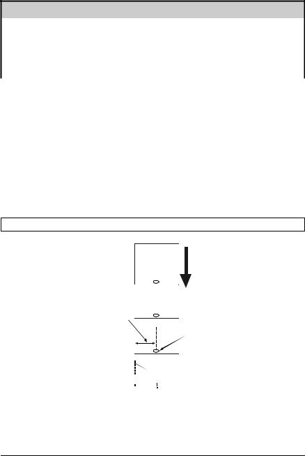
Depending of your media type, take a measurement from the left-justified media edge across to the center of the TOF mark as suggested in the table above. The following example illustrates the measurement of notched media.
; Note: Reflective marks are placed on the underside of the media.
Media
Movement
Measurement
Notch

 Left-Justified
To simplify the adjustment, the AMS uses Reference Letter designators that correspond to the following TOF mark distances:
10 |
E-4203/E-4204/E-4304 |
Reference |
Distance of the TOF Mark Distance from the Media Edge |
|
Letter |
(inches) |
(millimeters) |
A |
.180 |
4.6 |
B |
.500 |
12.7 |
C |
.750 |
19.1 |
D |
1.00 |
25.4 |
E |
1.25 |
31.8 |
F |
1.50 |
38.1 |
G |
1.75 |
44.5 |
H |
2.00 |
50.8 |
I |
2.25 |
57.2 |
J |
2.50 |
63.5 |
K |
2.75 |
69.9 |
L |
3.00 |
76.2 |
Position the Adjustable Media Sensor as follows:
1. Based on the measurement made earlier, choose the Reference Letter that best corresponds to the location of your TOF mark.


 Reference
 Letters


 Setting Window
Top Slide


 Bottom
 Slide
Slide


Setting Window
 Reference Letters
E-4203/E-4204/E-4304 |
11 |
2.Use a finger to move the Bottom Slide until your selected Reference Letter appears in the Setting Window of the slide.
3.Use a finger to move the Top Slide until your selected Reference Letter appears in the Setting Window of the slide.
;Note: The Top and Bottom Slides must be positioned over the same Reference Letter for proper media sensor function.
4.Proceed to ‘Loading Media’ (Section 3.3).
3.3Loading Media
Load media into the printer as follows:
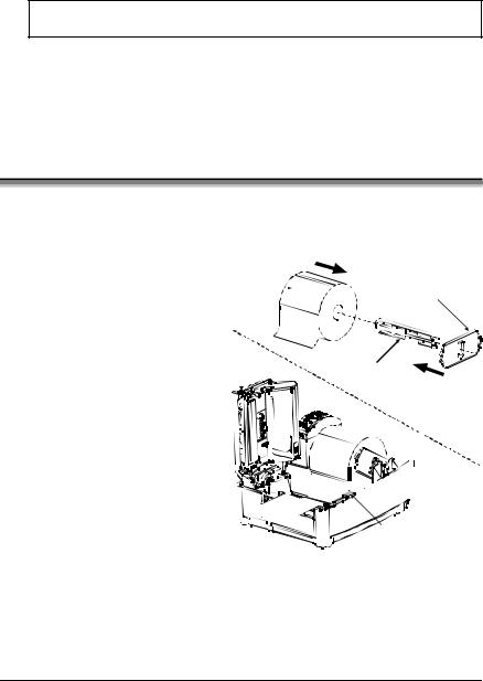
1.With the Cover open and the Printhead Carrier Assembly raised, remove the Media Hub and insert it through the Roll Media (with the labels spilling forward).
2.Place the Media Hub Flange (with its smooth side toward the media) onto the Media Hub.
3.Place the Media Hub, flange, and media onto the Standoffs in the printer.
4. Route the media through the printer, as shown below.
|
Roll |
|
|
|
Media Hub Flange |
|||||||||||
|
|
|
||||||||||||||
Media |
|
|
(smooth side toward media) |
|||||||||||||
Printhead |
|
|
|
|
|
|
|
|
|
|
|
|
|
|||
|
|
|
|
|
|
|
|
|
|
|
|
|
||||
Media |
||||||||||||||||
Carrier |
||||||||||||||||
|
|
|
Hub |
|||||||||||||


 Standoff
Printhead
Latch
12 |
E-4203/E-4204/E-4304 |
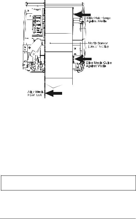
5. Slide the Media Guide and Media Hub Flange to the edge of the media.
6.Close the Printhead Carrier Assembly and press down until it locks into place.
7. Close the cover and press the Feed button several times to position the media and ensure proper tracking.
(If the printer does not correctly sense the top of each label, as denoted by the FAULT Light, it may be necessary to perform the Calibration Procedure, Section 4.6.)
; Note: The printer is factory set to use 4-inch media (and ribbon, if thermal transfer equipped). When using a different width of media/ribbon, please refer to Chapter 5.
E-4203/E-4204/E-4304 |
13 |
3.3.1 Loading Media for Peel Configuration
1. Open the cover.
2. Push the Printhead Latch down and raise the Printhead Carrier Assembly.
3. Place a roll of media (labels facing up) on the Media Hub and insert them into the printer. Slide the Media Hub Flange with its smooth side towards media onto the Media Hub.
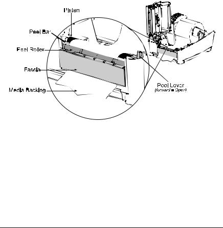
4. Pull the Peel Lever forward to the ‘Open’ position.
5. Remove 6 (152 mm) of labels from the backing. Route the Media Backing over the Platen and Peel Bar and behind the Peel Roller and Fascia as shown below.
6. Push the Peel Lever back to the ‘Closed’ position.
7.Close the Printhead Carrier Assembly and press down until it locks into place.
8. Close the cover and press the Feed button several times to advance the media and ensure proper tracking. The labels will separate automatically as it is fed through the printer. (If the printer does not correctly sense the top of each label, as denoted by the FAULT Light, it may be necessary to perform the Calibration Procedure, Section 4.6.)
14 |
E-4203/E-4204/E-4304 |
3.4 Loading Ribbon
Ribbon is required with thermal transfer media. If your printer is equipped with the thermal transfer option and if you will be using thermal transfer media, load ribbon as follows:
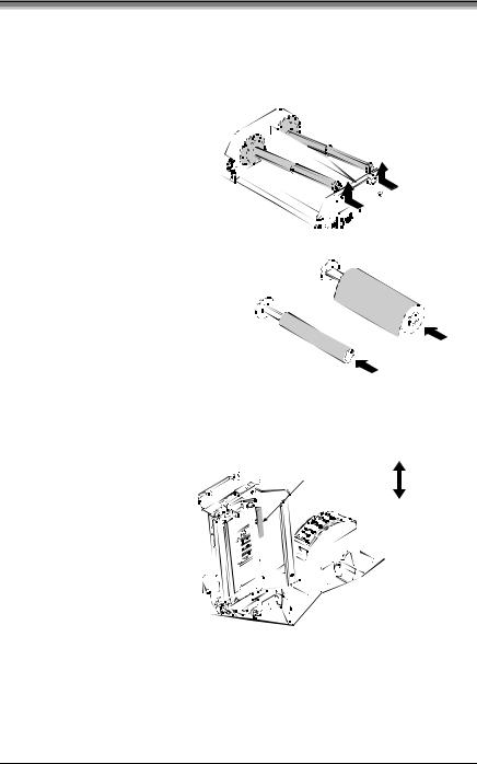
1. Open the cover.
2. Remove both Ribbon Hubs.


 Push in and lift


 to remove the Hubs
3. Slide a roll of Ribbon onto one of the Ribbon Hubs and an Empty Core onto the other hub.
Slide a Ribbon onto a Hub and |
Ribbon |
|||
an Empty Core onto a Hub |
|
|
||
|
|
|
|
|
Empty Core |
|
|
||
|
|
|||
|
|
|||
4. Push the Printhead Latch down and raise the Printhead Carrier Assembly.
5. Slide the Media Type Switch into the ‘Transfer’ position.
Direct
Media Type Switch
Transfer
E-4203/E-4204/E-4304 |
15 |
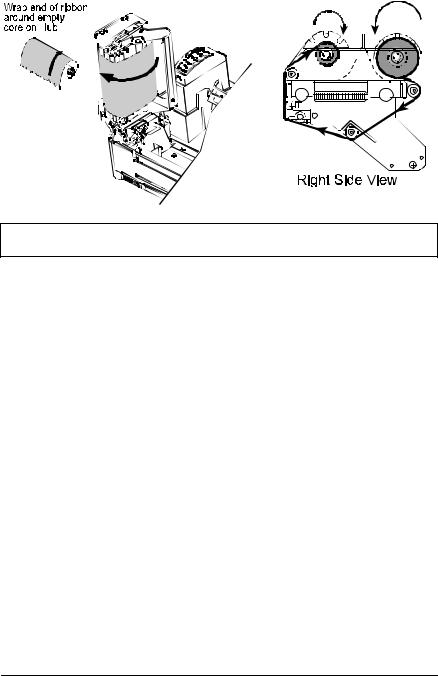
6. Place the Ribbon Hubs back into the printer and route the ribbon through the Printhead Carrier Assembly, as shown below.
; Note: Ensure the inked side of the ribbon faces the media and NOT the printhead.
7. The ‘Media Type’ setting within the printer’s setup must be set to ‘Thermal Transfer’ to print using a ribbon. See Section 4.4.
16 |
E-4203/E-4204/E-4304 |
3.5Flash Memory Expansion
The printer can be equipped with the optional Flash Memory Expansion. This additional memory can be used to store label formats and fonts (for font downloading instructions, see Section 5.8).
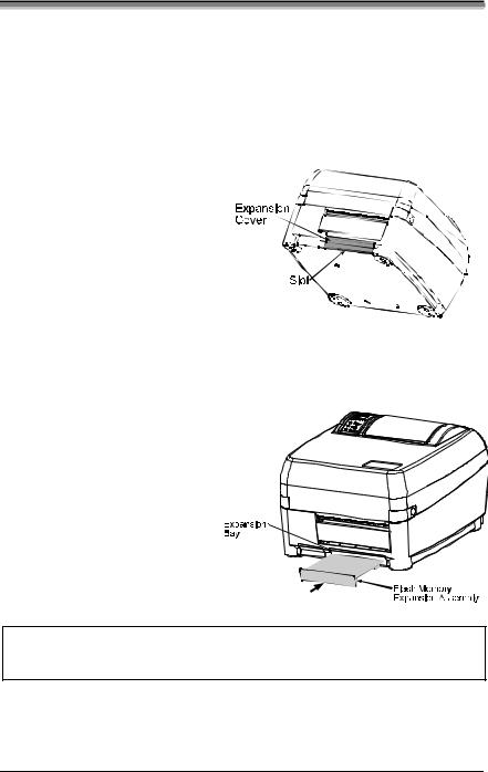
To install the Flash Memory Expansion:
1. Turn the power off and unplug the printer. Remove any installed media from the printer.
2. Using a coin, flathead screwdriver, or similar object, insert it into the Slot on the underside of the printer and gently pry the Expansion Cover from the printer.
3. With its connector facing down, as shown, gently insert the Flash Memory Expansion Assembly into the Expansion Bay until the assembly is firmly seated.
4. Plug in and turn on the printer.
; Note: When using a blank expansion module for the first time, the printer will automatically format it upon power-up; this initial format can take up to one minute to perform.
E-4203/E-4204/E-4304 |
17 |

18 |
E-4203/E-4204/E-4304 |
 Loading...