

Page 1
Operator’s Manual
Page 2

Page 3

Copyright Information
CG Triumvirate is a trademark of Agfa Corporation.
CG Times based upon Times New Roman under license from the Monotype Corporation.
Windows is a registered trademark of the Microsoft Corporation.
All other brand and product names are trademarks, service marks, registered trademarks, or registered
service marks of their respective companies.
Limitation of Liability
In no event shall Datamax-O’Neil be liable to the purchaser for any indirect, special or consequential
damages or lost profits arising out of or relating to Datamax-O’Neil’s products, or the performance or a
breach thereof, even if Datamax-O’Neil has been advised of the possibility thereof. Datamax-O’Neil’s
liability, if any, to the purchaser or to the customer of the purchaser hereunder shall in no event exceed
the total amounts paid to Datamax-O’Neil hereunder by the purchaser for a defective product.
In no event shall Datamax-O’Neil be liable to the purchaser for any damages resulting from or related to
any failure or delay of Datamax-O’Neil in the delivery or installation of the computer hardware, supplies or
software or in the performance of any services.
Some states do not permit the exclusion of incidental or consequential damages, and in those states the
foregoing limitations may not apply. The warranties here give you specific legal rights, and you may have
other legal rights which vary from state to state.
Firmware (Software) Agreement
The enclosed Firmware (Software) resident in the Printer is owned by Licensor or its suppliers and is
licensed for used only on a single printer in the user’s Trade or Business. The User agrees not to, and
not to authorize or permit any other person or party to, duplicate or copy the Firmware or the
information contained in the non-volatile or programmable memory. The firmware (Software) is
protected by applicable copyright laws and Licensor retains all rights not expressly granted. In no event
will Licensor or its suppliers be liable for any damages or loss, including direct, incidental, economic,
special, or consequential damages, arising out of the use or inability to use the Firmware (Software).
Information in this document is subject to change without notice and does not represent a commitment on
the part of Datamax-O’Neil Corporation. No part of this manual may be reproduced or transmitted in any
form or by any means, for any purpose other than the purchaser's personal use, without the expressed
written permission of Datamax-O’Neil Corporation.
All rights reserved
Copyright © 2010, Datamax-O’Neil
Part Number: 88-2348-01, Revision C
Important Safety Instructions
This printer has been carefully designed to provide years of safe reliable performance. As with all types of
electrical equipment, however, there are a few basic precautions that should be taken to avoid personal
injury or damage to the device:
• Carefully read the installation and operating instructions provided with the printer.
• Read and follow all warning and instruction labels on the printer.
• Place the printer on a flat, stable surface.
• Do not insert anything into the ventilation slots or openings on the printer.
• Do not place the printer on or near a heat source.
• Do not use the printer near water. Never spill liquid into the printer.
• Be certain the power source is within the voltage rating and frequency listed for the printer. If you
are unsure, check with your dealer, an electrician, or local power company.
• Do not place the power cord where it can be stepped on. If the power cord becomes damaged or
frayed, replace it immediately.
• Only qualified, trained service technicians should attempt to repair the printer.
Page 4
Agency Compliance and Approvals
C US
Listed
UL60950-1, First Edition, Information Technology Equipment
CSA C22.2 No. 60950-1-03, First Edition
IEC 60950-1 :2001, First Edition
The manufacturer declares under sole responsibility that this product conforms to the
following standards or other normative documents:
EMC: EN 55022 (2006) Class A
EN 50024 (1998)
Safety: This product complies with the requirements of IEC 60950-1:2001, First Edition
Gost-R
GB4943-2001, GB9254-1998, GB17625-1-2003
FCC: This device complies with FCC CFR 47 Part 15 Class A.
Note: This equipment has been tested and found to comply with the limits for a Class A digital
device, pursuant to Part 15 of the FCC Rules. These limits are designed to provide
reasonable protection against harmful interference when the equipment is operated in a
commercial environment. This equipment generates, uses, and can radiate radio
frequency energy, and if not installed and used in accordance with the instructions in
this manual, it may cause harmful interference to radio communications. Operation of
this equipment in a residential area is likely to cause harmful interference in which case
the user will be required to correct the interference at his own expense.
Page 5

s
t
n
e
t
n
o
C
C
C
G
e
t
G
e
t
G
e
t
1.1 Introduction ........................................................................................................ 1
1.2 Unpacking the Printer ........................................................................................... 1
o
o
t
i
n
t
i
n
t
i
n
g
g
g
n
n
S
t
S
t
S
e
t
e
t
a
r
t
e
d
.
a
r
t
a
r
.
t
e
d
.
.
t
e
d
.
.
n
n
.
.
.
.
.
.
.
.
.
.
.
t
t
.
.
.
.
.
.
.
.
.
.
.
.
.
.
.
.
.
.
.
s
s
.
.
.
.
.
.
.
.
.
.
.
.
.
.
.
.
.
.
.
.
.
.
.
.
.
.
.
.
.
.
.
.
.
.
.
.
.
.
.
.
.
.
.
.
.
.
.
.
.
.
.
.
.
.
.
.
.
.
.
.
.
.
.
.
.
.
.
.
.
.
.
.
.
.
.
.
.
.
.
.
.
.
.
.
.
.
.
.
.
.
.
.
.
.
.
.
.
.
.
.
.
.
.
.
.
.
.
.
.
.
.
.
.
.
.
.
.
.
.
.
.
.
.
.
.
.
.
.
.
.
.
.
.
.
.
.
.
.
.
.
.
.
.
.
.
.
.
.
.
.
.
.
.
.
.
.
.
.
.
.
.
.
.
.
.
.
.
.
.
.
.
.
.
.
.
.
.
.
.
.
.
.
.
.
.
.
.
.
.
.
.
.
.
.
.
.
.
.
.
.
.
.
.
.
.
.
.
.
.
.
.
.
.
.
.
.
.
.
.
.
.
.
.
.
1
.
.
.
.
.
1
.
.
.
.
.
1
P
r
i
n
t
e
r
S
e
t
u
p
.
.
.
.
.
.
.
.
.
.
.
.
.
.
.
.
.
.
.
.
.
.
.
.
.
.
.
.
.
.
.
.
.
.
.
.
.
.
.
.
.
.
.
.
.
.
.
.
.
.
.
.
.
.
.
.
.
.
.
.
.
.
.
.
.
.
.
.
.
.
.
.
.
.
.
.
.
.
.
.
.
.
.
.
.
P
r
i
n
t
e
r
S
e
t
u
p
.
.
.
.
.
.
.
.
.
.
.
.
.
.
.
.
.
.
.
.
.
.
.
.
.
.
.
.
.
.
.
.
.
.
.
.
.
.
.
.
.
.
.
.
.
.
.
.
.
.
.
.
.
.
.
.
.
.
.
.
.
.
.
.
.
.
.
.
.
.
.
.
.
.
.
.
.
P
r
i
n
t
e
r
S
e
t
u
p
.
.
.
.
.
.
.
.
.
.
.
.
.
.
.
.
.
.
.
.
.
.
.
.
.
.
.
.
.
.
.
.
.
.
.
.
.
.
.
.
.
.
.
.
.
.
.
.
.
.
.
.
.
.
.
.
.
.
.
.
.
.
.
.
.
.
.
.
.
.
2.1 Introduction ........................................................................................................ 3
2.2 Connecting the Printer .......................................................................................... 3
2.2.1 Power Connections ..................................................................................... 3
2.2.2 Interface Connections ................................................................................. 4
2.3 Identifying the Media Sensor.................................................................................. 5
2.3.1 Positioning the Adjustable Media Sensor ........................................................ 6
2.4 Loading Media...................................................................................................... 7
2.4.1 Peeling...................................................................................................... 9
2.5 Loading Ribbon .................................................................................................. 10
P
r
i
n
t
e
r
O
p
e
r
a
t
i
o
n
.
.
.
.
.
.
.
.
.
.
.
.
.
.
.
.
.
.
.
.
.
.
.
.
.
.
.
.
.
.
.
.
.
.
.
.
.
.
.
.
.
.
.
.
.
.
.
.
.
.
.
.
.
.
.
.
.
.
.
.
.
.
.
.
P
r
i
n
t
e
r
O
p
e
r
a
t
i
o
n
.
.
.
.
.
.
.
.
.
.
.
.
.
.
.
.
.
.
.
.
.
.
.
.
.
.
.
.
.
.
.
.
.
.
.
.
.
.
.
.
.
.
.
.
.
.
.
.
.
.
.
.
.
.
.
.
P
r
i
n
t
e
r
O
p
e
r
a
t
i
o
n
.
.
.
.
.
.
.
.
.
.
.
.
.
.
.
.
.
.
.
.
.
.
.
.
.
.
.
.
.
.
.
.
.
.
.
.
.
.
.
.
.
.
.
.
.
.
.
.
.
3.1 Introduction ...................................................................................................... 13
.
.
.
.
.
.
.
.
.
.
.
.
.
.
.
.
.
.
.
.
.
.
.
.
.
.
.
.
.
.
.
.
.
.
.
.
.
.
.
.
.
.
.
.
.
.
.
.
.
.
.
.
.
.
.
.
.
.
.
.
.
.
.
.
.
.
.
.
.
.
.
.
.
.
.
.
.
.
.
.
.
.
.
.
.
.
.
.
.
.
.
.
.
.
.
.
.
.
.
.
.
.
.
.
.
.
.
.
.
.
.
.
.
.
.
3
.
.
.
.
.
.
3
.
.
.
.
.
3
.
.
1
3
.
.
1
3
.
.
.
1
3
3.2 Indicator Lights.................................................................................................. 13
3.3 Multi-Function Buttons........................................................................................ 14
Ready Mode Functions ........................................................................................ 14
Delayed Power-Up Functions................................................................................ 14
3.4 Printer Configuration Tools .................................................................................. 15
3.5 Printer Configuration Utility (DMXConfig) ............................................................... 16
3.6 Windows Driver.................................................................................................. 18
3.7 Media Calibration ............................................................................................... 20
3.7.1 Quick Calibration...................................................................................... 20
3.7.2 Empty Calibration..................................................................................... 20
i
Page 6

3.7.3 Standard Calibration................................................................................. 21
3.8 Internal Labels................................................................................................... 23
3.8.1 Database Configuration Label..................................................................... 23
3.8.2 Test Label ............................................................................................... 23
3.8.3 Hex Dump Label....................................................................................... 24
M
a
i
n
t
e
n
a
n
c
e
a
n
d
A
d
j
u
s
t
m
e
n
t
s
.
.
.
.
.
.
.
.
.
.
.
.
.
.
.
.
.
.
.
.
.
.
.
.
.
.
.
.
.
.
.
.
.
.
.
.
.
.
.
.
.
.
.
.
.
.
.
.
.
.
.
.
.
.
.
.
.
.
.
M
a
i
n
t
e
n
a
n
c
e
a
n
d
A
d
j
u
s
t
m
e
n
t
s
.
.
.
.
.
.
.
.
.
.
.
.
.
.
.
.
.
.
.
.
.
.
.
.
.
.
.
.
.
.
.
.
.
.
.
.
.
.
.
.
.
.
.
.
.
.
.
.
.
.
.
M
a
i
n
t
e
n
a
n
c
e
a
n
d
A
d
j
u
s
t
m
e
n
t
s
.
.
.
.
.
.
.
.
.
.
.
.
.
.
.
.
.
.
.
.
.
.
.
.
.
.
.
.
.
.
.
.
.
.
.
.
.
.
.
.
.
.
.
.
4.0 Introduction ...................................................................................................... 25
4.1 Cleaning the Printhead........................................................................................ 26
4.2 Media Width Adjustment ..................................................................................... 28
4.3 Printhead Adjustment ......................................................................................... 29
4.4 Printhead Replacement ....................................................................................... 30
4.5 Downloading Firmware and Fonts ......................................................................... 31
T
r
o
u
b
l
e
s
h
o
o
t
i
n
g
.
.
.
.
.
.
.
.
.
.
.
.
.
.
.
.
.
.
.
.
.
.
.
.
.
.
.
.
.
.
.
.
.
.
.
.
.
.
.
.
.
.
.
.
.
.
.
.
.
.
.
.
.
.
.
.
.
.
.
.
.
.
.
.
.
.
T
r
o
u
b
l
e
s
h
o
o
t
i
n
g
.
.
.
.
.
.
.
.
.
.
.
.
.
.
.
.
.
.
.
.
.
.
.
.
.
.
.
.
.
.
.
.
.
.
.
.
.
.
.
.
.
.
.
.
.
.
.
.
.
.
.
.
.
.
.
.
.
.
T
r
o
u
b
l
e
s
h
o
o
t
i
n
g
.
.
.
.
.
.
.
.
.
.
.
.
.
.
.
.
.
.
.
.
.
.
.
.
.
.
.
.
.
.
.
.
.
.
.
.
.
.
.
.
.
.
.
.
.
.
.
.
.
.
.
5.0 Introduction ...................................................................................................... 33
5.1 Troubleshooting Tips........................................................................................... 33
S
p
e
c
i
f
i
c
a
t
i
o
n
s
.
.
.
.
.
.
.
.
.
.
.
.
.
.
.
.
.
.
.
.
.
.
.
.
.
.
.
.
.
.
.
.
.
.
.
.
.
.
.
.
.
.
.
.
.
.
.
.
.
.
.
.
.
.
S
p
e
c
i
f
i
c
a
t
i
o
n
s
.
.
.
.
.
.
.
.
.
.
.
.
.
.
.
.
.
.
.
.
.
.
.
.
.
.
.
.
.
.
.
.
.
.
.
.
.
.
.
.
.
.
.
.
.
.
S
p
e
c
i
f
i
c
a
t
i
o
n
s
.
.
.
.
.
.
.
.
.
.
.
.
.
.
.
.
.
.
.
.
.
.
.
.
.
.
.
.
.
.
.
.
.
.
.
.
.
.
.
I
n
t
e
r
n
a
l
M
e
n
u
.
.
.
.
.
.
.
.
.
.
.
.
.
.
.
.
.
.
.
.
.
.
.
.
.
.
.
.
.
.
.
.
.
.
.
.
.
.
.
I
n
t
e
r
n
a
l
M
e
n
u
.
.
.
.
.
.
.
.
.
.
.
.
.
.
.
.
.
.
.
.
.
.
.
.
.
.
.
.
.
.
.
I
n
t
e
r
n
a
l
M
e
n
u
.
.
.
.
.
.
.
.
.
.
.
.
.
.
.
.
.
.
.
.
.
.
.
.
.
.
.
.
.
.
.
.
.
.
.
.
.
.
.
.
.
.
.
.
.
.
.
.
.
.
.
.
.
.
.
.
.
.
.
.
.
.
.
.
.
.
.
.
.
.
.
.
.
.
.
.
.
.
.
.
.
.
.
.
.
.
.
.
.
.
.
.
.
.
.
.
.
.
.
.
.
.
.
.
.
.
.
.
.
.
.
.
.
.
.
.
.
.
.
.
.
.
.
.
.
.
.
.
.
.
.
.
.
.
.
.
.
.
.
.
.
.
.
.
.
.
.
.
.
.
.
.
.
.
.
.
.
.
.
.
.
.
.
.
.
.
.
.
.
.
.
.
.
.
.
.
.
.
.
.
.
.
.
.
.
.
.
.
.
.
.
.
.
.
.
.
.
.
.
.
.
.
.
.
.
.
.
.
.
.
.
.
.
.
.
.
.
.
.
.
.
.
.
.
.
.
.
.
.
.
.
.
.
.
.
.
.
.
.
.
.
.
.
.
.
.
.
.
.
.
.
.
.
.
.
.
.
.
.
.
.
.
.
.
.
.
.
.
.
.
.
.
.
.
.
.
.
.
.
.
.
.
.
.
.
.
.
.
.
.
.
.
.
.
.
.
.
.
.
.
.
.
.
.
.
.
.
.
.
.
.
.
.
.
.
.
.
.
.
.
.
.
.
.
.
.
.
.
.
.
.
.
.
.
.
.
.
.
.
.
.
.
.
.
.
.
.
.
.
.
.
.
.
.
.
.
.
.
.
.
.
.
.
.
.
.
.
.
.
.
.
.
.
.
.
.
.
.
.
.
.
.
.
.
.
.
.
.
.
.
.
.
.
.
.
.
.
.
.
.
.
.
.
.
.
.
.
.
.
.
.
.
.
.
.
.
.
.
.
.
.
.
.
.
.
.
.
.
2
5
.
.
.
.
.
.
2
5
.
.
.
2
5
.
.
3
3
.
.
3
3
.
.
.
3
3
.
.
3
5
.
.
3
5
.
.
.
3
5
.
.
3
9
.
.
3
9
.
.
.
3
9
B.1 Buttons............................................................................................................. 39
B.2 Printer Setup Mode - Button Functions .................................................................. 39
B.2.1 Printer Setup Menu List............................................................................. 41
B.2.2 Menu Items and Values............................................................................. 42
B.2.3 Step by Step Modification of the Printer Setup.............................................. 45
B.3 Label Alignment ................................................................................................. 46
B.3.1 Label Alignment = YES.............................................................................. 46
B.3.2 Label Alignment = AUTO ........................................................................... 47
B.3.3 Label Alignment = NO............................................................................... 47
B.3.4 Label Alignment Troubleshooting ................................................................ 48
B.4 Calibration Mode – Button Functions ..................................................................... 50
ii
Page 7

B.4.1 Auto Media Sensor Calibration.................................................................... 51
B.4.2 Manual Media Sensor Calibration ................................................................ 52
.
.
.
.
.
.
.
.
.
.
.
.
.
.
.
.
.
.
.
.
.
.
.
W
i
r
e
d
a
n
d
W
i
r
e
l
e
s
s
S
e
t
u
p
.
.
.
.
.
.
.
.
.
.
.
.
.
.
.
.
.
.
.
.
.
.
.
.
.
.
.
.
.
.
.
.
.
.
.
.
.
.
.
.
.
.
.
.
.
.
.
.
.
.
.
.
.
.
.
.
.
.
W
i
r
e
d
a
n
d
W
i
r
e
l
e
s
s
S
e
t
u
p
.
.
.
.
.
.
.
.
.
.
.
.
.
.
.
.
.
.
.
.
.
.
.
.
.
.
.
.
.
.
.
.
.
.
.
.
.
.
.
.
.
.
.
.
.
.
.
.
.
W
i
r
e
d
a
n
d
W
i
r
e
l
e
s
s
S
e
t
u
p
.
.
.
.
.
.
.
.
.
.
.
.
.
.
.
.
.
.
.
.
.
.
.
.
.
.
.
.
.
.
.
.
.
.
.
.
.
.
.
.
.
.
.
.
C.1 Network Card Reset............................................................................................ 53
C.2 Network Card Setup ........................................................................................... 53
C.3 Network Card Setup - Wireless (Infrastructure Mode).............................................. 54
C.4 Printer’s Internal Web Pages................................................................................ 55
C.5 DMX Config Utility .............................................................................................. 59
C.6 Installing the Printer Driver.................................................................................. 61
.
.
.
.
.
.
.
.
.
.
.
.
.
.
.
.
.
.
.
.
.
.
.
.
.
.
.
.
.
.
5
3
.
.
.
.
.
.
.
.
.
5
3
.
.
.
5
3
G
G
G
l
o
s
s
a
r
y
.
.
.
.
.
.
.
.
.
.
.
.
.
.
.
.
.
.
.
.
.
.
.
.
.
.
.
.
.
.
.
.
.
.
.
.
.
.
.
.
.
.
.
.
.
.
.
.
.
.
.
.
.
.
.
.
.
.
.
.
.
.
.
.
.
.
.
.
.
.
.
.
.
.
.
.
.
.
.
.
.
.
.
.
.
.
.
.
.
.
.
.
.
.
.
.
l
o
s
s
a
r
y
.
.
.
.
.
.
.
.
.
.
.
.
.
.
.
.
.
.
.
.
.
.
.
.
.
.
.
.
.
.
.
.
.
.
.
.
.
.
.
.
.
.
.
.
.
.
.
.
.
.
.
.
.
.
.
.
.
.
.
.
.
.
.
.
.
.
.
.
.
.
.
.
.
.
.
.
.
.
.
.
.
.
.
.
.
.
.
.
l
o
s
s
a
r
y
.
.
.
.
.
.
.
.
.
.
.
.
.
.
.
.
.
.
.
.
.
.
.
.
.
.
.
.
.
.
.
.
.
.
.
.
.
.
.
.
.
.
.
.
.
.
.
.
.
.
.
.
.
.
.
.
.
.
.
.
.
.
.
.
.
.
.
.
.
.
.
.
.
.
.
.
.
.
.
.
.
.
.
.
.
.
.
.
.
.
.
.
.
.
.
.
.
.
.
.
.
.
.
.
.
.
.
6
3
.
.
.
6
3
.
.
.
6
3
iii
Page 8

Page 9
d
e
t
r
a
t
S
g
n
i
t
t
e
G
G
G
1
1
1
1
.
1
1
.
1
1
.
1
The E-Class Mark II printer (hereafter referred to as “the printer”) is user-friendly thermal printing device that
blends quality and durability in an affordable package to meet all of your labeling needs. This manual provides
the information necessary to operate and maintain the printer.
To begin printing labels or tags, refer to the instructions included with your software labeling program. For
your convenience, a Windows printer driver can be found on the Accessories CD-ROM, or it can be
downloaded from our website at http://www.datamax-oneil.com
formats, a copy of the Class Series 2 Programmer’s Manual also is included for your reference, or the manual
can be downloaded.)
1
.
2
1
.
2
1
.
2
I
n
t
r
o
d
u
c
t
k
k
u
k
u
i
c
t
i
c
t
i
i
n
g
i
n
g
i
n
g
I
n
t
r
o
n
n
t
p
p
p
d
r
o
d
a
c
a
c
a
c
I
n
U
n
U
U
e
e
o
n
o
n
o
t
t
t
n
h
h
h
t
t
e
P
e
P
e
P
t
t
r
r
r
n
i
n
i
i
n
t
e
r
i
n
i
n
t
e
r
t
e
r
g
g
S
S
t
t
r
a
r
a
. (If you wish to write custom programs or
t
t
e
e
d
d
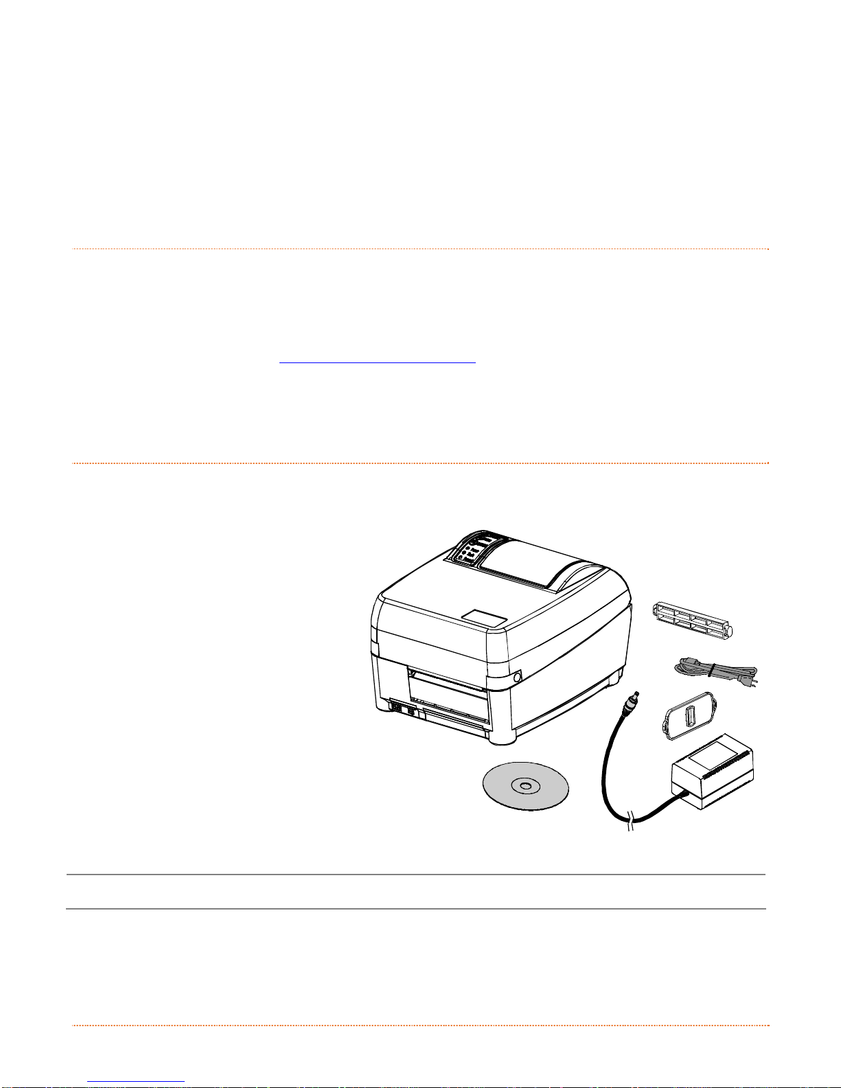
After removing the printer from the packaging material, check the contents of the box. In addition to the
printer, the following items should be present:
Power Supply
Accessories CD-ROM
Media Hub and Flange
Any special or additionally
ordered items
Additional Requirements
The following items are necessary to
generate labels:
Parallel, Serial, USB, or (if
equipped for LAN connectivity)
an Ethernet cable; see Section
2.2.2 for details.
Applicable media; see Appendix
A for details.
Contact customer support or your sales
representative for advice on the media
and software that may best be suited for
your application.
312
Chapter 1 – Getting Started 1
It is a good idea to save all packaging material for future use.
Page 10

2 Chapter 1 – Getting Started
Page 11
p
u
t
e
S
r
e
t
n
i
r
P
r
P
P
2
2
2
2
.
1
2
.
1
2
.
1
This section explains how to connect your printer, load media (including ribbon, i f equipped for thermal
transfer operation) and print a configuration label.
2
.
2
2
.
2
2
.
2
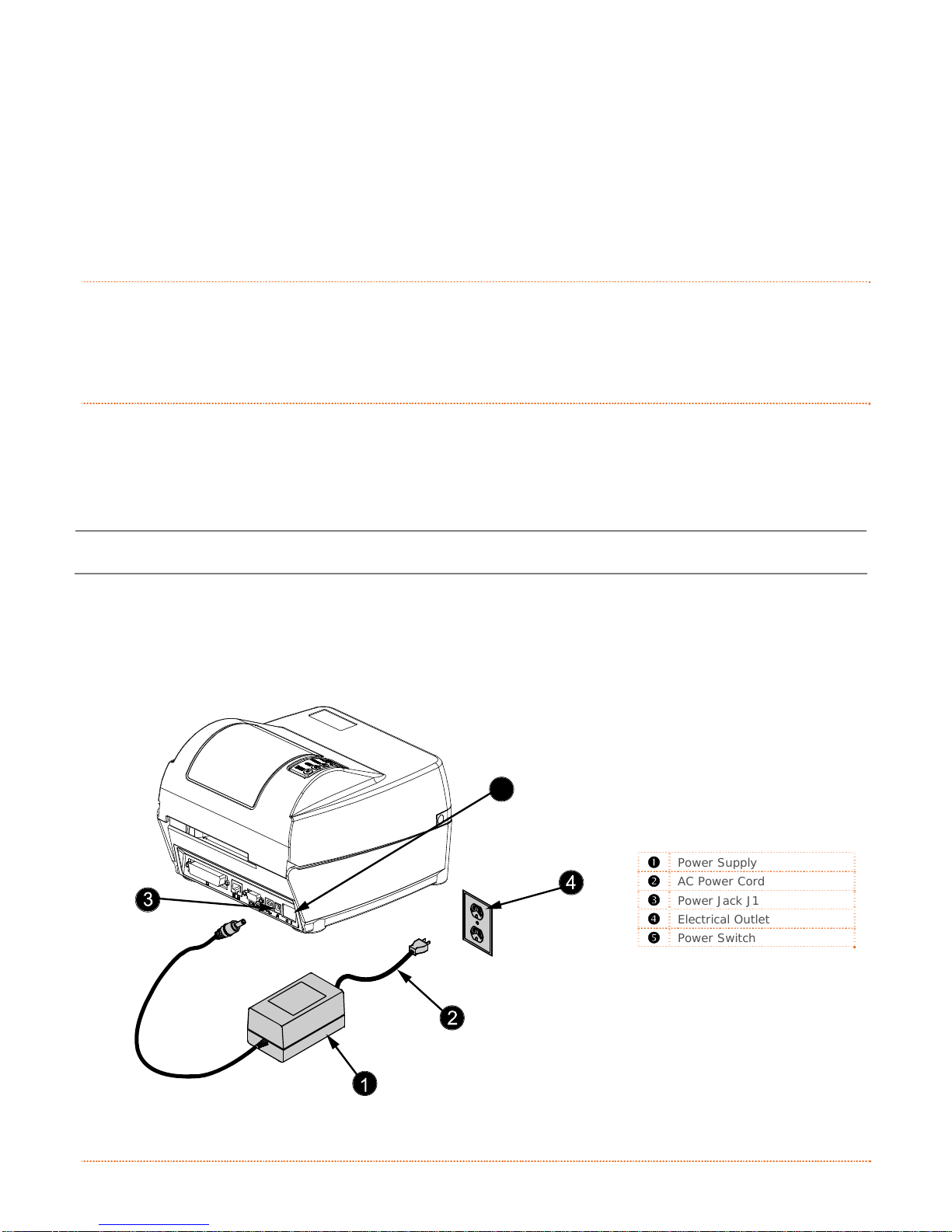
2.2.1 Power Connections
The printer is powered by an external auto-ranging power supply, which connects between the printer and an
electrical outlet. Ensure that the operating ranges of the power supply are compatible with your electrical
service (see Appendix A for details) then connect power as follows:
I
I
I
C
C
C
n
t
n
t
n
t
o
n
o
o
n
n
r
o
d
u
c
t
c
c
u
c
u
i
c
t
i
c
t
i
t
i
n
t
i
n
t
i
n
r
o
d
r
o
d
n
e
n
e
n
e
r
o
o
o
g
g
g
n
n
n
t
i
i
t
t
n
n
h
h
h
e
e
e
e
t
e
t
P
r
i
n
P
t
r
i
n
t
r
i
n
t
P
e
e
e
r
r
r
r
r
S
S
e
e
t
t
u
u
p
p
Before connecting power to the printer, ensure that the Power Switch is in the OFF (O) position.
a) Connect the Power Supply Plug to Jack J1 of the pri n ter.
b) Connect the AC Power Cord to the Power Supply.
c) Connect the AC Power Cord to an Electrical Outlet.
312
5
Power Supply
AC Power Cord
Power Jack J1
Electrical Outlet
Power Switch
Chapter 2 – Printer Setup 3
Page 12
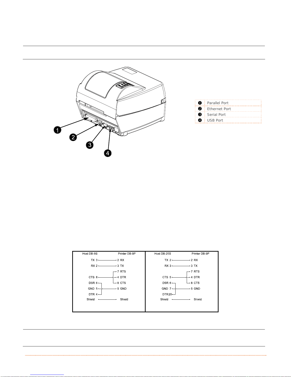
2.2.2 Interface Connections
The printer can be connected to the host system via the parallel, serial and USB ports.
Before connecting interface cables to the printer, ensure that the Power Switch is in the OFF (O) position.
312
Cable Requirements
Choose the correct cable when interfacing the printer to the host:
The Parallel Port supports parallel communications via a 36-pin male connector. Unidirectional
(forward channel) communications is supported when a Centronics
bidirectional communications (forward and reverse channels) is supported when an IEEE 1284
compliant cable and supporting host software is used.
The Ethernet Port (optional) supports Wired or Wireless LAN communications (see Appendix C
for information).
The Serial Port supports RS-232C communications via a DB-9 connector with specific pin-outs
(interface cable part numbers and pin-outs are given below; contact your reseller to order). Serial
port settings are menu-selectable and must match the host settings (see Section B.2).
Parallel Port
Ethernet Port
Serial Port
USB Port
IEEE 1284 cable is used, and
Part # 32-2483-01
The USB Port supports serial communications and requires a standard USB interface cable.
The printer automatically establishes communications with the first port through which valid data is
received. Afterward, a timeout period must be exceeded (or power must be cycled OFF and ON) to change
the established communications port.
4 Chapter 2 – Printer Setup
Part # 32-2301-01
Page 13

2
.
3
I
d
e
n
t
i
f
y
i
n
g
t
h
e
M
e
d
i
a
S
e
n
s
o
r
2
.
3
I
d
e
n
t
i
f
y
i
n
g
t
h
e
M
e
d
i
a
S
e
n
2
.
3
I
d
e
n
t
i
f
y
i
n
g
t
h
e
M
e
d
i
a
The printer is available with a Stationary or an Adjustable Media Sensor. Press the Printhead Latch and then
raise the Printhead Carrier Assembly to determine the type of sensor, and positioning requirement if any:
The Stationary Media Sensor (shown below) is immovable; if the printer is equipped with this
type of sensor, proceed to Section 2.4.
312
i
S
e
n
s
s
o
o
r
r
Printhead Latch
Printhead Carrier Assembly
Stationary Media Sensor
The Adjustable Media Sensor (shown below) requires positioning; if the printer is equipped with
this type of sensor, proceed to Section 2.3.1.
312
Printhead Latch
Printhead Carrier Assembly
Adjustable Media Sensor
Chapter 2 – Printer Setup 5
Page 14
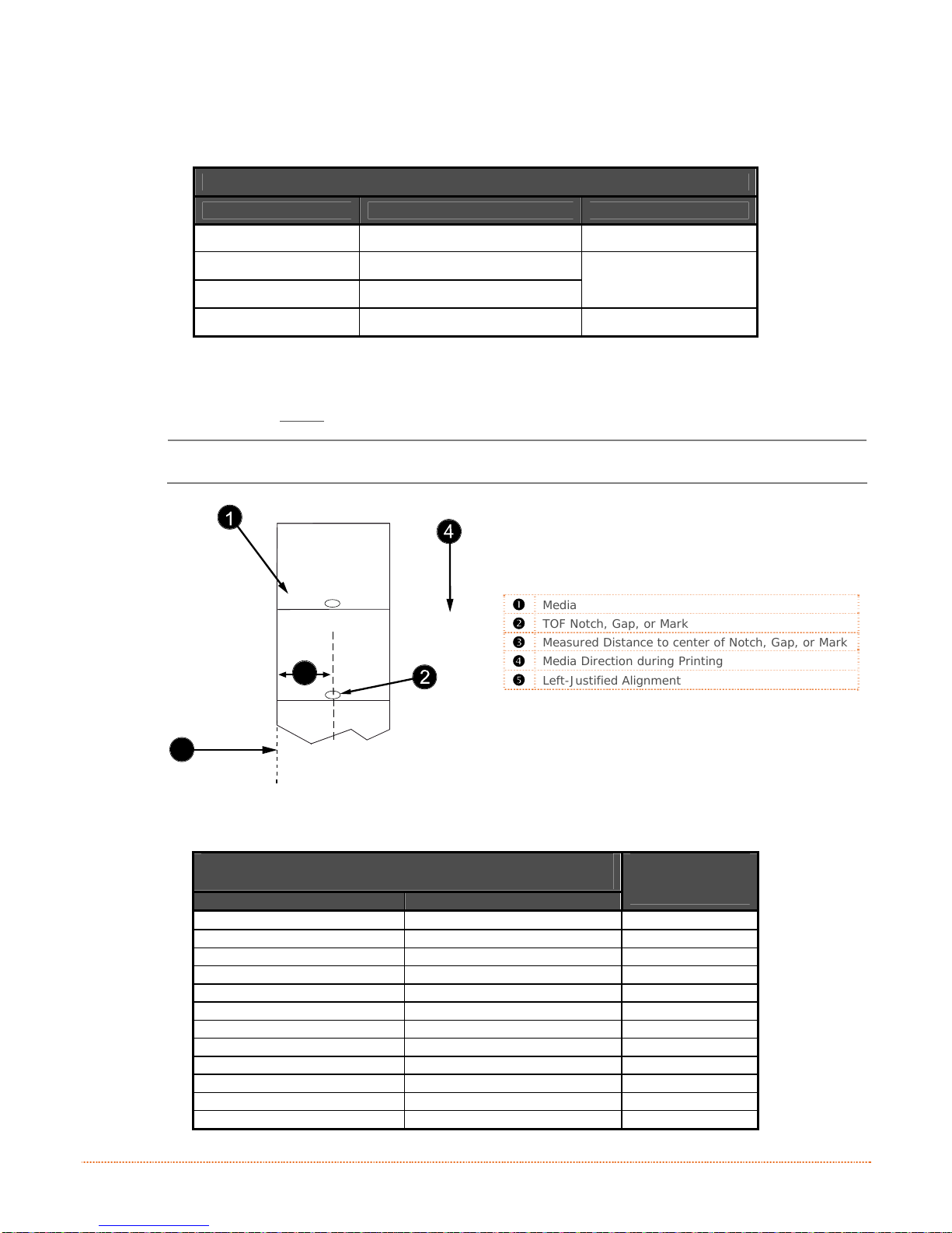
2.3.1 Positioning the Adjustable Media Sensor
The Adjustable Media Sensor (AMS) allows the printer to accept a wider variety of media configurations. The
table below defines general AMS positions for various media and Top of Form (TOF) types.
AMS Positioning
Media Type Sensor Location TOF Sensing Method
Continuous Center of the Media Continuous
Die-Cut Center of the Label
Notched Center of the Notch
Reflective Center of the Mark Reflective
Position the AMS as follows:
a) Measure from the left edge of the media (as oriented in the direction of movement during
printing) to the center
Reflective media must be placed into the printer with the TOF Marks facing downward.
of the TOF Notch, Gap, or Mark (see example below).
312
Media
TOF Notch, Gap, or Mark
Measured Distance to center of Notch, Gap, or Mark
Media Direction during Printing
3
Left-Justified Alignment
Gap
5
b) In the table below find the number closest to the TOF Notch, Gap, or Mark measurement made
above, and then select the corresponding AMS Reference Letter.
Measured Distance to center of Notch, Gap, or Mark
(inches) (millimeters)
.18 5 A
.50 13 B
.75 19 C
1.00 25 D
1.25 32 E
1.50 38 F
1.75 45 G
2.00 51 H
2.25 57 I
2.50 64 J
2.75 70 K
3.00 76 L
AMS
Reference
Letter
6 Chapter 2 – Printer Setup
Page 15
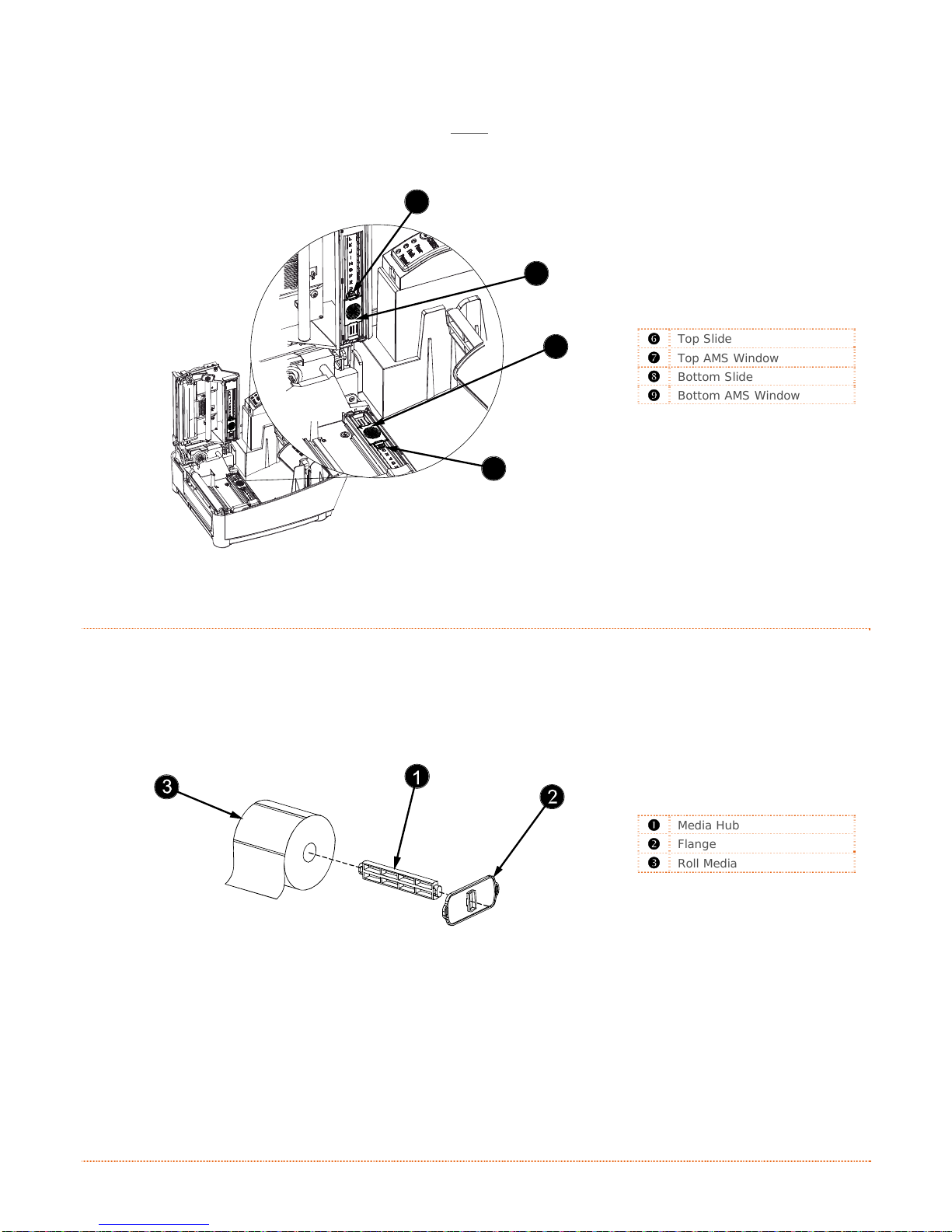
c) Sli de the Top A MS Window over the Reference Letter determined in Step b, above.
d) Slide the Bottom AMS Window over the same
e) Load media; see Section 2.4.
312
Reference Letter.
7
e
6
Top Slide
8
Top AMS Window
Bottom Slide
Bottom AMS Window
9
2
.
2
.
2
.
Load media as follows:
4
L
o
a
d
i
n
4
L
o
4
a
L
o
a
a) Slide the Media Hub through the Roll Media core.
b) With the Roll Media positioned so that the labels will unwind forward over the top, slide the Flange
(smooth side in) onto the Media Hub.
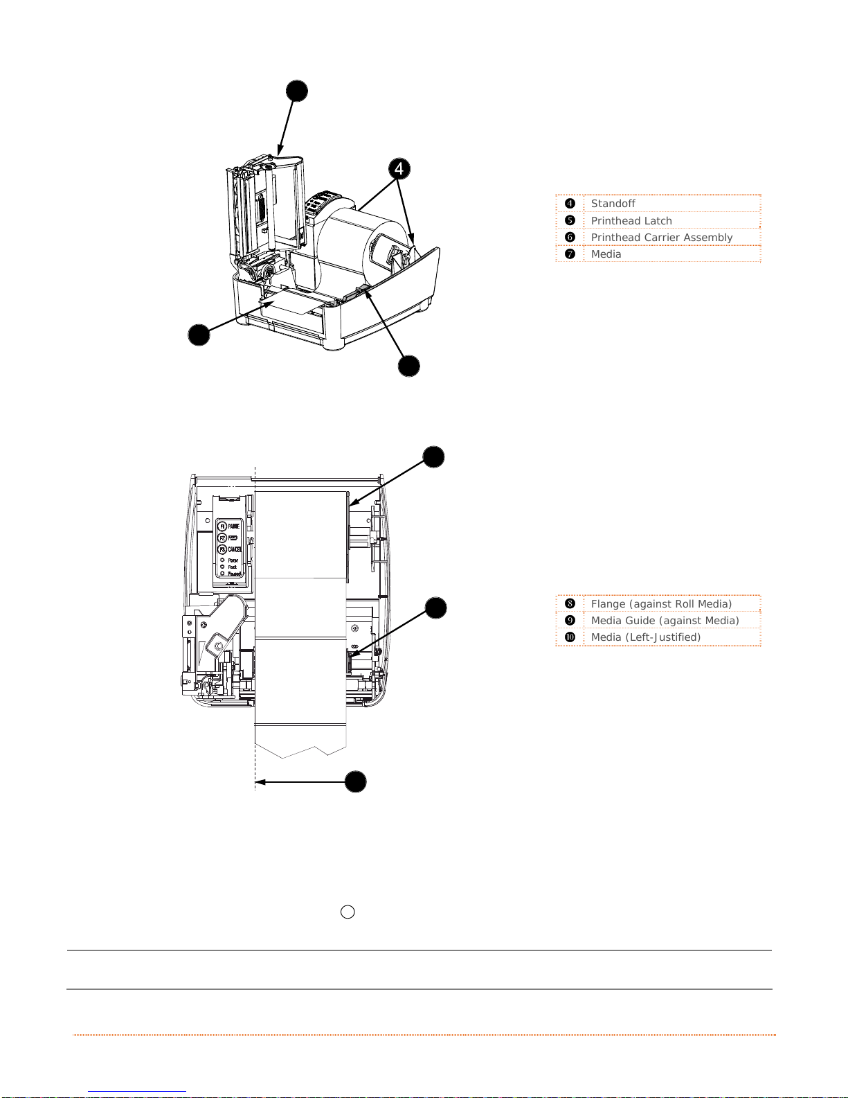
c) Press the Printhead Latch and raise the Printhead Carrier Assembly.
d) Lower the Media Hub onto the Standoffs in the printer.
d
d
g
i
n
g
i
n
g
M
M
M
e
e
e
d
d
d
i
a
i
a
i
a
312
Media Hub
Flange
Roll Media
Chapter 2 – Printer Setup 7
Page 16
312
6
Standoff
Printhead Latch
Printhead Carrier Assembly
Media
7
5
e) Route Media through the printer, as shown.
312
8
Flange (against Roll Media)
9
10
Media Guide (against Media)
Media (Left-Justified)
f) Slide the Roll Media completely leftward and then position the Flange against the roll.
g) Slide the Media leftward and then position the Media Guide lightly against the side of the media.
h) Lower the Printhead Carrier Assembly and press downward until locked.
F2
i) Close the cover and press the
Button several times to advance media (if the Fault Light
illuminates, see Section 3.7.)
The printer is factory set to use 4-inch long gap media. If using another media length or type (for
example, continuous media), printer setup must be reconfigured; see Section 3.4
.
8 Chapter 2 – Printer Setup
Page 17
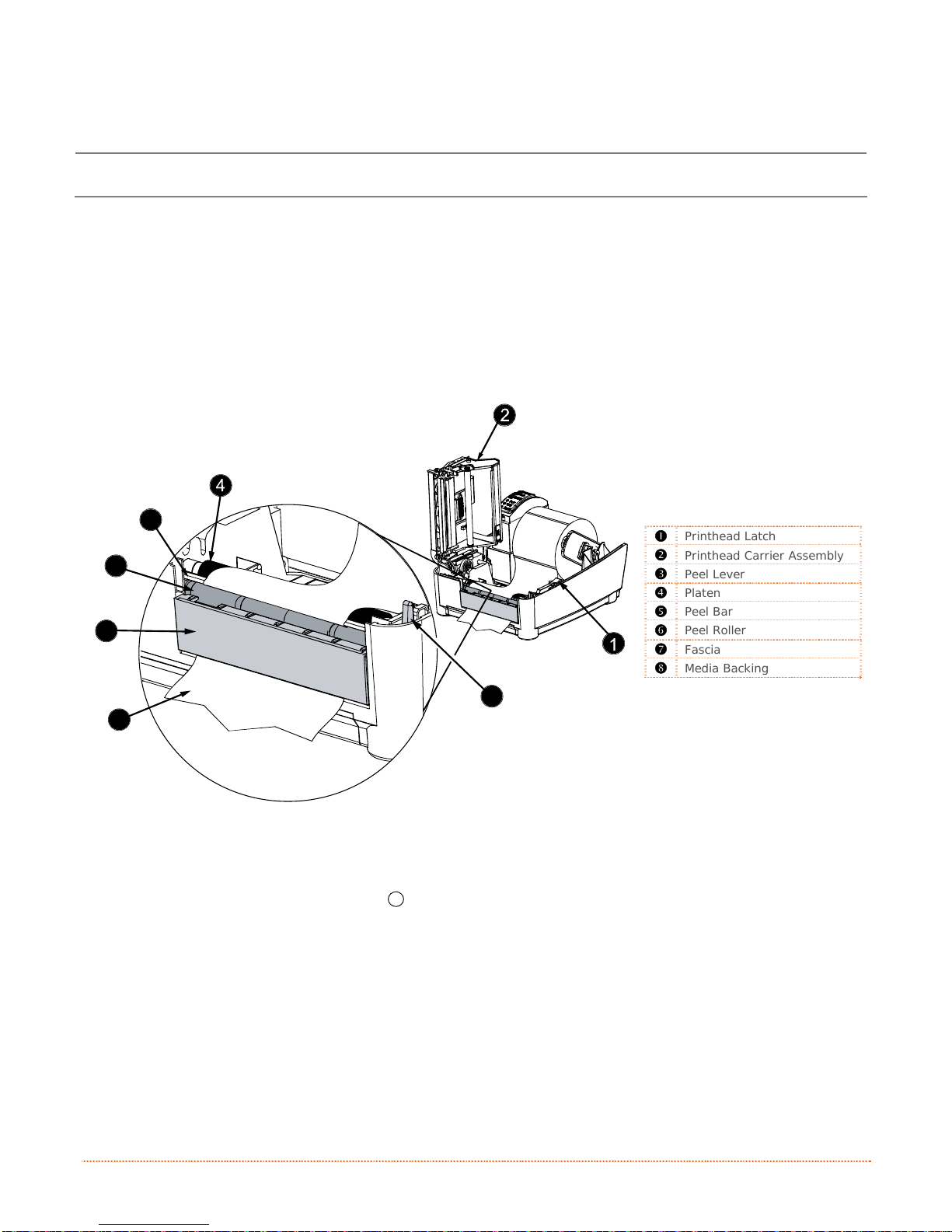
2.4.1 Peeling
Load media for peeling (if the printer is equipped with the option) as follows:
6
7
8
When using the Peel Mechanism do not exceed a print speed of 4 IPS.
a) Load media as described in Section 2.4.
b) Press the Printhead Latch and raise the Printhead Carrier Assembly.
c) Pull the Peel Lever forward.
d) Remove about 6 inches (150mm) of label material from the Media Backing.
e) Route the Media Backin g over the Platen and Peel Bar, and then behind the Peel Roller and Fascia,
as shown below.
312
5
Printhead Latch
Printhead Carrier Assembly
Peel Lever
Platen
Peel Bar
Peel Roller
Fascia
Media Backing
3
f) Push the Peel Lever backward.
g) Lower the Printhead Carrier Assembly and press downward until locked.
h) Close the cover then press the
separate automatically from the backing (if the Fault Light illuminates, see Section 3.7.)
Chapter 2 – Printer Setup 9
F2
Button several times to advance the media. The labels will
Page 18
2
.
5
L
o
a
d
i
n
g
R
i
b
b
o
n
2
.
5
L
o
a
d
i
n
g
R
i
b
2
.
5
L
o
a
d
i
n
g
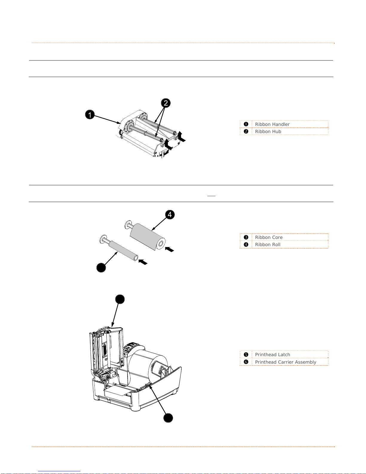
Ribbon, required when printing on thermal transfer media, is loaded as follows:
If equipped with the thermal transfer option, the printer is factory set to use ribbon; see Section 3.4 to
change this setting if using direct thermal media.
a) If installed in the Ribbon Handler, remove the Ribbon Hubs.
b
R
i
b
b
o
o
n
n
312
Ribbon Handler
Ribbon Hub
b) Slide a Ribbon Roll (with the leader positioned as shown below) onto a Ribbon Hub, and slide a
Ribbon Core onto the remaining Ribbon Hub.
Ensure the inked side of the ribbon faces toward the media, not the printhead.
312
3
c) Press the Printhead Latch and raise the Printhead Carrier Assembly.
312
Ribbon Core
Ribbon Roll
6
10 Chapter 2 – Printer Setup
Printhead Latch
Printhead Carrier Assembly
5
Page 19
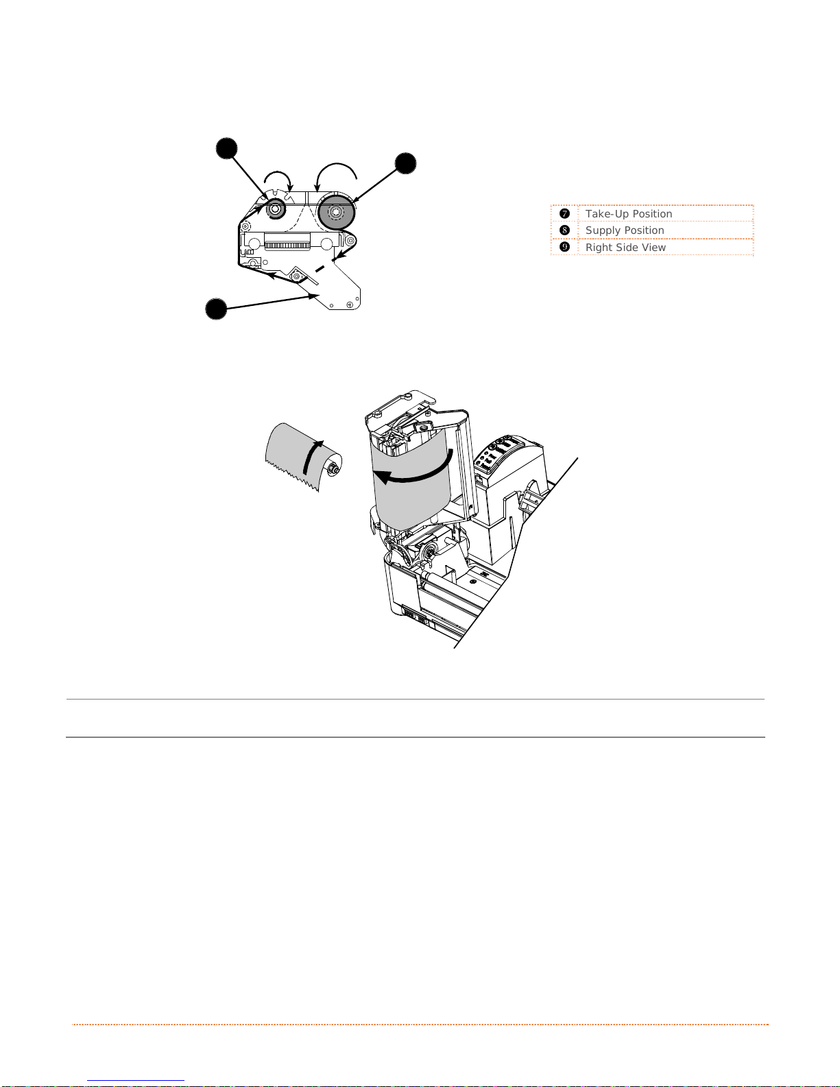
d) Place the Ribbon Hub with the Core into the Take-Up Position in the Ribbon Handler and place the
Ribbon Hub with the Ribbon Roll into the Supply Position. Route the ri bbon from the supply roll
around the Printhead Carrier Assembly to the take-up roll, as shown below.
312
7
8
Take-Up Position
Supply Position
Right Side View
9
e) Affix the leader of the ribbon to the Core using tape. Rotate the Ribbon Hub several times to
secure the ribbon.
312
f) Lower the Printhead Carrier Assembly and press downward until locked.
Media Type (in the Setup Menu) must be set to Thermal Transfer when using ribbon; see Section 3.4.
Chapter 2 – Printer Setup 11
Page 20

12 Chapter 2 – Printer Setup
Page 21

e
t
n
i
r
P
r
P
P
3
3
3
3
.
1
3
.
1
3
.
1
The Front Panel consists of three indicator lights
and multi-function buttons, as detailed in the
following sections.
I
n
t
r
o
d
u
c
t
I
n
t
r
o
I
n
d
t
r
o
d
u
u
c
c
i
t
i
t
i
r
o
o
o
n
n
n
i
i
n
n
t
t
e
e
r
r
r
O
O
O
p
p
p
e
e
e
r
r
r
a
a
a
t
t
t
i
i
i
o
o
o
n
n
n
3
.
2
I
n
d
i
c
a
t
o
r
L
i
g
h
t
s
3
.
2
I
n
d
i
c
a
t
o
r
L
i
3
.
2
I
n
d
i
c
a
t
o
Three Indicator Lights provide a quick visual reference of printer operations and conditions, as defi ned below:
All three indicators will be ON during power-up initialization and following a reset.
g
r
L
i
g
(Normal power-up)
Normal Mode
h
h
t
s
t
s
Power
Fault
Paused
Indicates the printer is on
Indicates a top of form or mechanical
error has occurred
Solid On:
‘Paused’ stat e
Blinking:
receiving data from the host
Indicates the printer is in the
Indicates the printer is
Chapter 3 – Printer Operation 13
Page 22
3
3
3
.
3
M
u
l
t
i
-
F
u
n
c
t
i
o
n
B
u
t
t
o
n
s
.
3
M
u
l
t
i
-
F
u
n
c
t
i
o
n
B
u
t
.
3
M
u
l
t
i
-
F
u
n
c
t
i
o
n
B
u
t
t
t
o
o
n
n
s
s
Three buttons (F1, F2, and
F3
perform different functions depending upon the mode of the printer:
)
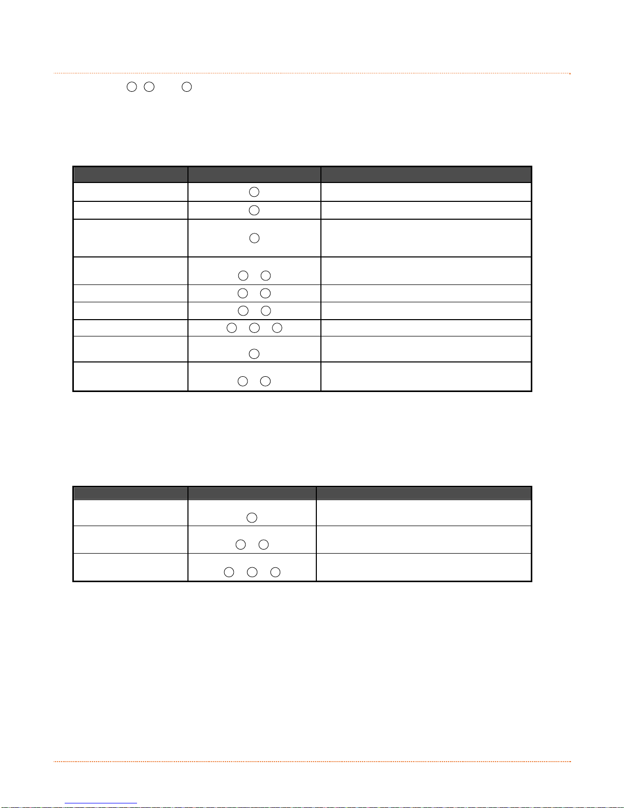
Ready Mode Functions
Control, calibration, and test functions can be performed when the printer is idle. Initiate the desired function
by pressing the respective button (or button combination) as detailed below.
Function Button(s) Description
Pause
Feed Media / Clear Fault
Cancel
Soft Reset
Print Test Label
Print Configuration Label
Print Ethernet Label
Quick Calibration
Empty Calibration
F1
F2
F3
Press and Hold
F1
Press and Hold
Press and Hold
F3
F1
+
F2
F1
+
F2
F3
+
+ F2 +
F2
F2
F1
+
F3
Pauses and un-pauses the printer
Feeds one label or clears fault condition
Cancels the current batch of labels. Press the
PAUSE Button to print the next batch of labels in
the print buffer.
Resets the printer
Prints the Test Label
Produces Database Configuration and Test Label
Prints the printers Ethernet configuration
Performs Quick Calibration; see Section 3.7.1.
Performs Empty Calibration; see Section 3.7.2.
Delayed Power-Up Functions
Some system functions can be initiated during power-up, as detailed below. Initiate the desired function by
turning ON the printer and, while all 3 lights are ON, pressing and holding the respective button combination
until all lights turn OFF.
Function Button(s) Description
Hex Dump
Level 1 Reset
Level 2 Reset
Press and Hold
F2
Press and Hold
Press and Hold
F1
F3
F1
+
+ F2 +
F3
Enters Hex Dump Mode; see Section 3.8.3.
Resets the printer to a saved configuration file.
Resets the printer to the factory default settings.
14 Chapter 3 – Printer Operation
Page 23

3
.
4
P
r
i
n
t
e
r
C
o
n
f
i
g
u
r
a
t
i
o
n
T
o
o
l
s
3
.
4
P
r
i
n
t
e
r
C
o
n
f
i
g
u
r
a
t
i
o
n
T
3
.
4
P
r
i
n
t
e
r
C
o
n
f
i
g
u
r
a
t
i
o
The printer contains many user adjustable parameters. These parameters are configurable using a few
methods. The table below lists the most popular ways of configuring the printer and the advantages of each.
Choose the method that best addresses your application.
Method Description Pros Cons For More Info
DMXConfig (located on the
Accessories CD-ROM) is a
Windows based configuration
DMXConfig
Program*
Internal Web
Pages*
utility that allows the user to
make changes to the existing
printer setup via a direct
connection to the host computer’s
serial, USB, or parallel
connection.
Internal web pages are simple
HTML pages that can be accessed
with any web browser via the
optional Ethernet port.
n
o
T
o
o
l
s
o
l
s
Easy to use, gives the
user the most control
of the printer.
Easy to use. Printer
can be configured from
any host connected to
the network regardless
of physical location or
host operating system.
No additional software
required.
Software must be
installed on a Windows
based host computer.
Printer must be
equipped with an
Ethernet option.
Depending on the
complexity of the
network, initial
connection may not be
possible until network
parameters are set via
another method.
See
Section 3.5
See
Appendix C.4
Windows
Driver
Internal Menu
System
DPL
Programming
Commands
* Recommended methods
The Windows printer driver
(located on the Accessories CDROM).
Internal menu system uses the
front panel buttons to navigate to
desired printer settings. Feedback
is printed directly on the label
stock.
DPL Programming Language
commands can be built into
custom label formats or sent
individually to the printer.
Many applications
require use of driver
for printing from 3
party applications. This
can be an all in one
solution for some users
that do not require
advanced setups.
No host or software
required.
DPL commands can be
built directly into label
formats which can
configure the printer
on the fly.
rd
Requires installation of
a driver on a Windows
based host.
Only basics parameters
can be configured.
Complicated
procedure.
Requires loading of
label and ribbon (if
equipped).
DPL programming
knowledge needed.
See
Section 3.6
See
Appendix B
See the
Class Series 2
Programmer’s
Manual
Chapter 3 – Printer Operation 15
Page 24

3
.
5
P
r
i
n
t
e
r
C
o
n
f
i
g
u
r
a
t
i
o
n
U
t
3
.
5
P
r
i
n
t
e
r
C
o
n
f
i
g
u
r
a
t
i
o
3
.
5
P
r
i
n
t
e
r
C
o
n
f
i
g
u
r
DMXConfig (located on the Accessories CD-ROM) is a Windows-based configuration utility that allows the
user to make changes to the existing printer setup via a direct connection to the host computer’s serial,
USB, or parallel ports.
DMXConfig Features:
Allows Real-Time Control/Query of Printer Configuration
Define and Save Optimal Configurations for Applications
Saved Configurations can be Shared with other Printers and Sent via Email
Download Files, Formats and Fonts
Query Memory Modules
Be sure to use the DMXConfig utility located on the Accessories CD-ROM that is included with your
A new feature of DMXConfig allows the use of Datamax-O’Neil Windows Driver for bidirectional
communications and configuration. Before this feature can be used, a small setting change must be made to
the printer driver’s properties.
Right-click on the printer driver icon and select Properties. Click on the Advanced Tab and select "Print directly
to the printer", then click OK.
printer. Older versions might not operate correctly with some printers. For the latest version please
visit our web site at http://www.datamax-oneil.com
a
n
t
i
o
n
i
U
t
i
U
t
i
(
D
M
X
C
o
n
f
i
g
)
l
i
t
y
(
D
M
X
C
o
l
i
t
y
(
D
M
l
i
t
y
X
C
o
n
n
f
i
g
)
f
i
g
)
16 Chapter 3 – Printer Operation
Page 25

Once you have installed the DMXConfig utility:
1. Connect the host to the printer with a
serial or parallel cable.
2. Turn ON the printer.
3. Launch the DMXConfig utility.
4. Query the printer by using the Query
Printer toolbar button (top-left). This
will connect to the printer and get the
current printer settings.
5. At this point you may browse the tabs
and make any changes necessary to the
printer configuration. Once complete,
send the new settings to the printer
using the Configure Printer toolbar
button.
(The example below illustrates changing the
Media Type setting to Thermal Transfer.
Other parameters can be changed using this
procedure as well.)
6. Select the Media Settings tab then in
the Media Type drop-down box select
Thermal Transfer.
7. Send the settings to the printer using
the Configure Printer toolbar button.
The printer is now configured to use
thermal transfer media. You may close the
DMXConfig utility and begin printing using
ribbon.
Chapter 3 – Printer Operation 17
Page 26

3
.
6
W
i
n
d
o
w
s
D
r
i
v
e
r
3
.
6
W
i
n
d
o
w
s
D
r
3
.
6
W
i
n
d
o
w
s
The Windows driver is located on the Accessories CD-ROM included with your printer. For the latest version
please visit our web site at http://www.datamax-oneil.com
Installing the Windows Driver:
Place the Accessories CD-ROM included with your printer
into your computers CD-ROM drive.
Once the CD-ROM starts select Install Windows Driver
from the main menu and follow the instructions on the
screen to install.
When prompted, select your printer from the list, (i.e.
Datamax E-4xxx). Continue to follow the on-screen
instructions to install the driver.
i
D
r
v
e
r
i
v
e
r
18 Chapter 3 – Printer Operation
Page 27

Important Notes:
The Windows driver functions the same as any other Windows printer. While built-in help files provide
information on all settings, there are some important setting parameters that should be observed for trouble
free printing:
Page Setup Tab: Stock
It is important that the Stock setting matches the
size of the label you are using. If you cannot find a
match for your label click New and enter the
dimensions of your label.
Options Tab: Print Speed & Printhead Temperature
These two settings will have the greatest effect on
print quality. Some label stocks will require more
heat and slower print speeds to generate a quality
image.
The Windows application software used to create the label format will likely have a "Page Setup" screen. This
will also need to match the size of the label you are using.
Chapter 3 – Printer Operation 19
Page 28

3
.
7
M
e
d
i
a
C
a
l
i
b
r
a
t
i
o
n
3
.
7
M
e
d
i
a
C
a
l
i
b
r
3
.
7
M
e
d
i
a
C
a
Calibration ensures correct media detection.
3.7.1 Quick Calibration
Quick Calibration should be performed as part of the media loading routine to fine-tune the sensing
parameters.
This calibration is not necessary when using continuous stock.
Calibrate the printer as follows:
1. Ensure that the printer is ON and in an idle state (i.e., not off-line) with media loaded, the media sensor
2. Press and hold the
3.7.2 Empty Calibration
Empty Calibration calibrates the media sensor for the Out of Stock condition. Calibrate the printer as follows:
1. Ensure that the printer is ON and in an idle state with media removed.
2. Press and hold the
Media containing large gaps may require a change in the Paper Out Distance before proceeding;
see Section 3.5.
adjusted, and the sensor type selected.
the data. There are two possible outcomes:
Upon completion, one of the following lights will flash five times to denote the result of the auto
calibration attempt:
Power Light = Successful calibration.
Fault Light = Unsuccessful calibration, try again. If the calibration continues to fail, proceed to Section
3.7.3.
a
l
i
b
r
a
F2
Button until one label has been output then release. Wait for the printer to process
F2
F1
Buttons for a few seconds.
+
t
i
o
n
t
i
o
n
20 Chapter 3 – Printer Operation
Page 29

3.7.3 Standard Calibration
The Standard Calibration can be performed using the DMXConfig Utility (see Section 3.5), or via the front
panel buttons (see Appendix B).
Once you have installed the DMXConfig utility and the printer is properly loaded with media, proceed with
calibration as follows:
1. Connect the host to the printer with a serial
or parallel cable.
2. Turn ON the printer.
3. Launch the DMXConfig utility.
4. Query the printer by using the Query Printer
toolbar button (top-left). This will connect to
the printer and get the current printer
settings.
5. Select the Sensor Calibration Tab and then
click the Media Calibration Wizard button.
When prompted click OK to start the
calibration wizard.
6. The Calibration Wizard will now prompt you to
Load Stock. Ensure that media is properly
loaded in the printer then close the printhead
and click OK.
Chapter 3 – Printer Operation 21
Page 30

7. The Calibration Wizard will now prompt you to
Load Backing. Peel off a few labels and
position the backing material in the media
sensor. Close the printhead and click OK.
8. The Calibration Wizard will now prompt you to
Remove Stock. Remove media and backing
from the printer. Close the printhead and click
OK.
9. The Calibration Wizard will now respond with
Passed Calibration; click OK. Reinstall media.
Close the printhead and press the
to test the calibration. Each press of the
Button labels should advance one label.
If the calibration was unsuccessful, retry the
procedure beginning at Step 5.
F2
Button
F2
22 Chapter 3 – Printer Operation
Page 31

3
.
8
I
n
t
e
r
n
a
l
L
a
b
e
l
s
3
.
8
I
n
t
e
r
n
a
l
L
a
3
.
8
I
n
t
e
r
n
a
The following section details the resident information and test labels.
b
l
L
a
b
e
e
l
s
l
s
3.8.1 Database Configuration Label
The Database Configuration Label provides information
including the printer firmware version, memory allocations,
enabled options, and label-counter data.
Print a Database Configuration Label as follows:
Load with media (4 inch wide) and ribbon (if printing with
thermal transfer media), then press the
simultaneously.
F2
F3
Buttons
+
3.8.2 Test Label
The Test Label can be used to evaluate the current settings for print quality, label tracking, and print
positioning.
Print a Test Label as follows:
With the printer loaded with media (4-inch wide), and ribbon (if thermal
transfer printing), simultaneously press the
F1
+ F2
Buttons.
Inconsistent patterns and streaks can indicate a dirty printhead; see Section 4.1 for cleaning instructions.
Chapter 3 – Printer Operation 23
Page 32

3.8.3 Hex Dump Label
The Hex Dump Label is a useful tool in the diagnosis of problems including communi cations handshaking and
DPL syntax errors. To generate a Hex Dump Label the printer enters into Hex Dump Mode. In this mode, all
data sent to the printer will be immediately output in hexadecimal code, along with the printable ASCII
equivalents. To decode this information, the Class Series 2 Programmer’s Manual is an essential reference. As
a final note, many software programs use bit mapping to construct the label, making diagnosis of this data
difficult. Contact Datamax-O’Neil Technical Support with any questions.
Enter Hex Dump Mode and print a Hex Dump Label as follows:
With the printer OFF, loaded with media (at least 4 inches wide) and ribbon (if printing with thermal transfer
media), press and hold the
Paused Light turns OFF. Now, all data received by the printer will be output in hexadecimal code, as shown
below.
F2
Button while turning the printer ON. Continue holding the F2 Button until the
To exit Hex Dump Mode, turn the printer OFF.
24 Chapter 3 – Printer Operation
Page 33

d
n
a
e
c
n
a
n
e
t
n
i
M
M
M
a
a
a
i
i
n
n
t
t
e
e
n
n
a
a
n
n
c
c
e
e
a
a
n
n
d
d
4
4
4
4
.
0
4
.
0
4
.
0
This section details the cleaning, adjusting, and troubleshooting tips for the printer. The following table
outlines the recommended maintenance schedule for the various printer parts.
I
n
I
n
I
n
Printhead
Platen Roller
Peel-Off Roller
A
A
A
t
r
o
d
u
c
t
i
o
t
r
o
d
t
u
r
o
d
u
Area Method Interval
n
c
t
i
o
n
c
t
i
o
n
Turn OFF the printer before cleaning the printhead.
Use solvent* applied with a cotton swab to clean
the printhead from end to end.
Turn OFF the printer. Rotate the platen roller and
clean it thoroughly with solvent* applied with a
cotton swab.
Rotate the peel-off roller and clean it thoroughly
with solvent* applied with a cotton swab.
d
d
j
j
u
u
s
s
t
t
m
m
m
t
s
u
j
d
e
e
e
n
n
t
t
s
After every roll of media.
After every roll of media.
After every roll of media.
s
s
t
n
Media Path Solvent* After every roll of media.
Peel/Tear Bar Solvent* As needed
Media Sensor Blown air or brush Monthly
Exterior Mild detergent or desktop cleaner. As needed
Interior Brush or vacuum cleaner As needed.
* A solvent containing isopropyl alcohol is recommended for use.
Isopropyl alcohol is a flammable solvent; always take the proper precautions when using this substance.
Chapter 4 – Maintenance and Adjustments 25
Page 34

4
.
1
C
l
e
a
n
i
n
g
t
h
e
P
r
i
n
t
h
e
a
d
4
.
1
C
l
e
a
n
i
n
g
t
h
e
P
r
i
n
t
4
.
1
C
l
e
a
n
i
n
g
t
h
e
P
Never use a sharp, hard, or abrasive object on the printhead.
If print quality declines (symptoms can include unreadable bar codes or streaks through text and graphics),
the typical cause is debris buildup on the printhead which, left unattended, can lead to premature dot failure.
Depending upon the supplies and printing parameters used, different cleaning methods are recommended.
h
r
i
n
t
h
e
e
a
a
d
d
Proper cleaning is critical. To maintain peak performance of the printer,
Datamax-O’Neil offers a complete line of cleaning products including
pens, cards, films and swabs. To learn more visit our website at
http://www.datamaxcorp.com/clean/
Cotton Swab Procedure
If printing with direct thermal media or thermal transfer media with wax ribbon, clean the pri nthead as
follows:
a) Turn OFF the Power Switch and unplug the printer. Press the Printhead Latch and then raise the
Printhead Carrier Assembly. Wait briefly for the printhead to cool.
b) Remove media and ribbon. Using a Cotton Swab moistened (not soaked) with isopropyl alcohol,
thoroughly clean the Printhead.
312
Streaks can indicate a dirty or a faulty printhead.
26 Chapter 4 – Maintenance Adjustments
3
Printhead Latch
Printhead Carrier Assembly
Printhead
Cotton Swab with Solvent
Page 35

Cleaning Card Procedure
If printing with direct thermal media, thermal transfer media with wax/resin ribbon combinations, or if the
Cotton Swab technique was not successful, clean the printhead as follows:
a) Press the Printhead Latch and then raise the Printhead Carrier Assembly. Wait briefly for the
Printhead to cool.
b) Remove media and ribbon then place a Cleaning Card under the Printhead (part number 70-2013-
01).
c) Lower the Printhead Carrier A ssembly and press downward until locked. Turn the Media Width
Thumbwheel counterclockwise as far as possible.
d) Close the cover then press
e) After the cleaning card has been run through the printer, reinstall media (and ribbon, if needed).
Plug in and turn ON the printer. Run a few sample labels and examine them. If streaking is still
present, use the Cleaning Film Procedure, below; otherwise, this completes cleaning.
F2
Button to initiate cleaning.
Cleaning Film Procedure
If printing with thermal transfer media and resin ribbon, when printing with a Heat Val ue of 22 or higher, or
when other methods prove unsuccessful, clean the printhead as follows:
a) Press the Printhead Latch and then raise the Printhead Carrier Assembly. Wait briefly for the
Printhead to cool.
b) Remove media and ribbon then place a sheet of Cleaning Film under the Printhead (part number
70-2087-01).
c) Lower the Printhead Carrier A ssembly and press downward until locked. Turn the Media Width
Thumbwheel counterclockwise as far as possible.
d) Close the cover then press
e) After the cleaning film has been run through the printer, turn OFF the Power Switch and unplug
the printer. Open the cover then raise the Printhead Assembly and wait briefly for the
Printhead to cool. Using a cotton swab moistened (not soaked) with isopropyl alcohol, clean the
Printhead then allow it to dry.
f) Reinstall media (and ribbon, if needed). Plug in and turn ON the printer. Run a few sample labels
and examine them. If streaking is still present, the Printhead may need to be replaced; see
Section 4.4.
F2
Button to initiate cleaning.
Chapter 4 – Maintenance and Adjustments 27
Page 36

4
.
2
M
e
d
i
a
W
i
d
t
h
A
d
j
u
s
t
m
e
n
t
4
.
2
M
e
d
i
a
W
i
d
t
h
A
d
j
u
s
t
4
.
2
M
e
d
i
a
W
i
d
t
h
A
d
The Media Width Thumbwheel adjusts the printer to accept various widths of media. Adjust for narrow media
by turning the Media Width Thumbwheel to the left (clockwise); conversely, adjust for wide media by turning
the Thumbwheel to the right (counterclockwise).
m
j
u
s
t
m
312
e
e
n
n
t
t
Media Width Thumbwheel
Printhead Carrier Assembly
Perform the media width adjustment as follows:
The reference numbers on the Media Width Thumbwheel do not correspond to specific media widths.
a) Load media into the printer. Print and examine a label (press the
b) If the printing appears too light on the right-hand side of the label (see example below), then
move the Media Width Thumbwheel counterclockwise. Print another label and examine it; make
additional adjustments as necessary.
F2
F1
Buttons simultaneously).
+
Direction
of Media
Movement
Example 1 – Too much adjustment
28 Chapter 4 – Maintenance Adjustments
If the media begins tracking too far right, the Media Width Thumbwheel should be adjusted clockwise.
Example 2 – Correct adjustment
Page 37

4
.
3
P
r
i
n
t
h
e
a
d
A
d
j
u
s
t
m
e
n
t
4
.
3
P
r
i
n
t
h
e
a
d
A
d
j
u
s
t
4
.
3
P
r
i
n
t
h
e
a
d
A
d
j
The Printhead Adjustment Screw, located on top of the Printhead Carrier Assembly, is used to mechanically
adjust print quality. Printhead placement is factory-set and should not need further adjustment; however,
with the different types and thicknesses of media, readjustment may be necessary when print quality suffers.
Printhead Adjustment should only be performed after attempting to improve print quality through the use of
other print quality controls (see Section 3.5).
To adjust the printhead, turn the Printhead Adjustment Screw until optimum print quality is obtained (some
trial and error may be necessary). Do not over tighten the Printhead Adjustment Screw.
u
s
t
m
m
312
e
e
n
n
t
t
3
Printhead Adjustment Set Screw
Printhead Carrier Assembly
Hex Screwdriver
Chapter 4 – Maintenance and Adjustments 29
Page 38

4
.
4
P
r
i
n
t
h
e
a
d
R
e
p
l
a
c
e
m
e
n
t
4
.
4
P
r
i
n
t
h
e
a
d
R
e
p
l
a
c
e
4
.
4
P
r
i
n
t
h
e
a
d
R
e
p
l
If the Printhead becomes damaged, replace it as follows:
Always follow proper Electro Static Discharge procedures when replacing the printhead.
If equipped with a Ribbon Handler, it is not necessary to remove the assembly as an access hole
has been provided.
a) Turn OFF the printer.
b) Loosen the Printhead Screw until it disengages from the Printhead.
c) Press the Printhead Latch and then raise the Printhead Carrier Assembly.
a
c
m
e
m
312
e
e
n
n
t
t
Printhead Latch
Printhead Carrier Assembly
Printhead Screw
Flathead Screwdriver
3
d) Remove the Printhead Cable from the Printhead Connector and then remove the Printhead.
312
7
5
Printhead
Printhead Connector
Printhead Cable
6
e) Carefully connect the Printhead Cable to the Printhead Connector of the new Printhead.
f) Position the Printhead in the Printhead Carrier Assembly and, after ensuring the Printhead Cable is
not pinched, tighten the Printhead Screw.
g) Clean then allow the Printhead to dry before use; see Section 4.1.
30 Chapter 4 – Maintenance Adjustments
Page 39

4
.
5
D
o
w
n
l
o
a
d
i
n
g
F
i
r
m
w
a
r
e
a
n
d
F
4
.
5
D
o
w
n
l
o
a
d
i
n
g
F
i
r
m
w
a
r
e
a
4
.
5
D
o
w
n
l
o
a
d
i
n
g
F
i
r
m
w
a
The operating programs and fonts for the printer are stored in Flash memory on the Main PCB. When program
updates and/or new features are added, they can be downloaded to the printer as follows:
1. Identify the new version for your model of printer from the Datamax-O’Neil FTP site at ftp.datamaxoneil.com and download it onto your computer’s hard drive or a floppy disk.
2. Ensure that the printer is connected to the host and that the power is ON. Using the DOS copy command,
enter:
Other programs (e.g., hyper-terminal and certain Windows Driver programs) may also be used to download
3. The Paused Light will flash during the download.
4. Following a successful download, the Paused Light will illuminate then the printer reset. The previous
If the printer fails to boot-up after an unsuccessful download, turn OFF the power. Simultaneously press and
hold the
this file.
printer setup will be unaffected unless substantial firmware data structure changes have occurred. Print a
Database Configuration Label to verify your new firmware version.
Following an unsuccessful download, the Fault Light will illuminate then the printer will reset. The
original firmware will remain operational. If the printer fails to reset, cycle power OFF and ON.
Try re-sending the file to the printer. If the failure continues, check the following possible causes:
An invalid or corrupted file is being downloaded - Ensure the file being downloaded is correct and
applicable for your printer model.
Possible communications error - Check the cable connection between the host and printer and
ensure that a quality, shielded cable is used.
Possible Flash memory problem - Call for service.
F1
+ F3
copy filename.zg lpt1/b
Buttons while powering ON the printer. Now, try downloading the file to the printer again.
n
r
e
a
n
d
d
o
F
o
F
o
n
n
n
t
s
s
t
t
s
Chapter 4 – Maintenance and Adjustments 31
Page 40

32 Chapter 4 – Maintenance Adjustments
Page 41

g
n
i
t
o
o
h
s
e
l
b
u
o
r
T
T
T
5
5
5
5
.
0
5
.
0
5
.
0
Occasionally, situations arise that require troubleshooting. Possible problem situations and potential solutions
are listed below. Contact a qualified technician for problems that persist or problems not covered in this
section.
5
.
1
5
.
1
5
.
1
The following section lists the symptoms and the associated page numbers of the topics covered. While not
every situation is addressed, you may find some tips helpful. After a correction action is taken press the FEED
Button to clear the alarm.
Unacceptable print quality:
The printer does not print or prints several labels at once:
The ribbon does not advance (the paper advances, but ribbon does not):
I
n
t
r
o
d
u
I
n
t
r
I
n
t
r
T
r
o
u
T
r
o
u
T
r
o
u
Dirty printhead: Clean the printhead (see Section 4.1).
The temperature setting may be incorrect for the media being used: Use the software program or
DPL commands adjust the Heat Setting and Print Speed.
A mismatched incorrect ribbon/media combination is being used: Check the types being used.
Faulty printhead: Replace it (see Section 4.4) or call for service.
The labels are incorrectly loaded: See the loading instructions on the inside cover of the printer, or
in Section 2.4.
The media is not calibrated: Calibrate it (see Section 3.7).
If equipped, the Adjustable Media Sensor may need to be repositioned (see Section 2.3.1).
The media sensor or sensor circuitry may be defective: Call for service.
The ribbon may be installed incorrectly: Ensure that the inked side of the ribbon faces the labels.
With most ribbons this can be verified by rubbing paper against the ribbon; the ink should smudge
the paper. Or, if using label stock, the sticky side of a label will pull off the ink.
A mismatched ribbon/paper combination is resulting in an insufficient amount of friction between
paper and ribbon: Ensure that the correct type of ribbon is being used with the media.
o
o
b
b
b
d
d
c
u
c
u
c
l
e
s
l
e
s
l
e
s
t
t
h
h
h
t
r
r
i
o
i
o
i
o
o
o
o
o
o
n
n
n
o
t
o
t
o
t
i
n
i
n
i
n
u
u
g
T
g
T
g
T
b
b
i
p
i
p
i
p
s
s
s
l
l
e
e
s
s
h
h
o
o
o
o
t
t
i
i
n
n
g
g
Chapter 5 – Troubleshooting 33
Page 42

Skips every other label (print quality is good, but every other label is skipped):
The label is formatted too close to the top edge of the label: Leave white space equal to 8-dot
rows (about .02 inch [.5mm]) at the top of the label.
The media is not calibrated: Calibrate it (see Section 3.7).
If equipped, the Adjustable Media Sensor may need to be repositioned (see Section 2.3.1).
The media sensor or media sensor circuitry may be defective: Call for service.
Unable to print rotations:
The characters are formatted outside the dimensions of the label: Check that the row/column
values provide enough room for the height of the image being printed.
Light print on the right side of the label:
The media width adjustment is set for narrow media: Adjust the media width (see Section 4.2).
The printhead is not properly aligned: Call for service.
The printhead carrier assembly is not latched down: Latch it.
Printer fails to power ON:
The AC wall outlet may be faulty: Try another outlet.
A fuse may be blown: Call for service.
The power supply may be faulty: Replace it.
Possible defective power switch: Call for service.
Label advances 1-2 inches before a fault indication:
The ribbon may be incorrectly installed. Ensure that the inked side of the ribbon faces the labels.
With most ribbons this can be verified by rubbing paper against the ribbon; the ink should smudge
the paper. Or, if using label stock, the sticky side of a label will pull off the ink.
A mismatched ribbon/paper combination is resulting in an insufficient amount of friction between
paper and ribbon: Ensure that the correct type of ribbon is being used with the media.
Label advances 16 inches before a fault indication:
Labels move excessively from side to side during printing:
The media may not be properly loaded: Reload it (see Section 2.4). When loading media ensure
that the media hub and media guide are against the media and that gaps or marks in the labels
are in line with the media sensor.
If equipped, the Adjustable Media Sensor may need to be repositioned (see Section 2.3.1).
The media sensor or media sensor circuitry may be defective: Call for service.
The media may not be properly loaded: Reload it (see Section 2.4). When loading media ensure
that the media hub and media guide are against the media and that gaps or marks in the labels
are in line with the media sensor.
The media width adjustment may not be properly set: Readjust it for the label width (see Section
4.2).
34 Chapter 5 – Troubleshooting
Page 43

i
f
i
c
e
p
S
p
S
p
S
A
A
A
Mechanical
Width 8.77 inches (22.3 cm)
Depth 10.0 inches (25.4 cm)
Height 7.05 inches (17.9 cm)
Weight 5.2 pounds (2.4 kg)
e
e
c
c
i
i
f
f
i
i
c
c
c
a
a
a
t
t
t
i
i
i
o
o
o
n
n
n
s
s
s
Operating Temperature
AC Input Voltage
Printing
Print Method Direct Thermal; Thermal Transfer (optional)
Print Speed
Resolution
Tear Bar Tear up
DRAM Memory 16MB
FLASH Memory 4MB
40 to 95 F (4 to 35 C)
Power Supply
105 VAC to 250 VAC / 50-60 Hz
E-4205e: 1 - 5 IPS (25.4 - 127mm/s)
E-4304e: 1 - 4 IPS (25.4 - 101.6mm/s)
E-4205e: 203 DPI (8 dots/mm)
E-4304e: 300 DPI (11.8 dots/mm)
Appendix A – Specifications 35
Page 44

Media / Ribbon
Media Types Rol l-Fed, Die-Cut, Continuous, Fan-Fold
Max. Media Width 4.3 inches (109mm)
Min. Media Width 0.75 inches (19mm)
Max. Print Width
Print Length Range
Media Thickness Range
Media Supply Roll Capacity 5 inches (127mm) O.D. on a 1 inch (25.4mm) core
Ribbon Width Range 1.0 - 4.3 inches (25 - 110mm)
E-4205e: 4.25 inches (108mm)
E-4304e: 4.12 inches (106mm)
.375 – 100 inches (9.5 - 2540mm); min length of 1 .25 inches
(31.8mm) with optional Cutter.
.0025 - .01 inches (.064 - .254mm); up to .007 inches (.117mm) with
optional Cutter;
Ribbon Roll Capacity
Matched to media: approx. 361 feet (110m) long with a 1.5 inch
(38mm) O.D. on a .5 inch core
Communications
Interface Ports (standard) USB, RS-232 (DB-9), & IEEE 1284 compliant Parallel (36 pin)
Baud Speed 600 to 38,400 bits per second (BPS)
Handshaking Xon/Xoff, CTS, DTR
Parity Even, Odd, or None
Stop Bits 1 or 2
Data Bits 7 or 8
Fonts
9 Bit Mapped Fonts rotated 0, 90, 180, and 270 degrees.
Embedded Bar Codes
32 embedded barcodes (see the Class Series 2 Programmer’s Manual for a detailed listing).
36 Appendix A – Specifications
Page 45

A
Approved Media
To achieve optimum print quality and maximum printhead life, Datamax-O’Neil specifies the use of DatamaxO’Neil brand media and ribbons. These supplies are specially formulated for use in our printers; use of other
supplies may affect the print quality, performance, and life of the printer or its components. For a current list
of approved media and ribbons for use in direct thermal and thermal transfer applications, please contact a
Media Representative at (407) 523-5650.
I
G
F
H
J
E
D
C
Description Max
B
[1]
Min
[1]
A Label width 4.09 1.00
B Backing width 4.30 1.00
C Gap between labels .25 .10
D Label length 24
E Total thickness .010
[3]
.375
[6]
.0025
[4]
F Notch opening width .50 .20
Distance from the edge of the media to
the media sensor aperture (left justified)
G
.175
.125
with the Adjustable Media Sensor option 2.94 .125
H Reflective mark width
I Distance between reflective marks 24
J Reflective mark length .25 .10
[1]
Units of measure are in inches.
[2]
The reflective (black) mark must be carbon based, placed on the backside of the
stock, and the reflectance shall be less than 10% at wavelengths of 950 and 640
nm.
[3]
The label length may vary up to 99 inches with printable area not exceeding the
maximum label length.
[4]
This distance is inclusive of the minimum gap between labels. Min length of 1.25
inches (31.8mm) with optional Cutter installed.
[5]
This distance is inclusive of the minimum reflective mark.
[6]
.007 inches (.117mm) w/Standard Cutter, .005 inches (.127mm) w/LD Cutter
[2]
4.10 .50
[3]
.375
[5]
Appendix A – Specifications 37
Page 46

38 Appendix A – Specifications
Page 47

u
n
u
u
u
n
n
n
e
e
e
c
t
c
t
c
n
n
i
o
n
s
o
o
n
n
s
s
i
t
i
u
u
I
I
I
B
B
B
B
.
1
B
.
1
B
.
1
Three buttons (PAUSE, FEED, and CANCEL) perform different functions based on the printer’s mode:
Normal: Normal printer functions; see Section 3.3.
Printer Setup: Allows changes to the operational settings; see Section B.2.
Calibration: Allows media calibration for the correct sensing of the top of form; see Section B.4.
B
.
2
B
.
2
B
.
2
B
u
t
t
o
n
s
B
u
t
B
P
P
P
t
u
t
t
r
i
n
r
i
n
r
i
n
o
n
s
o
n
s
t
e
r
S
t
e
r
S
t
e
r
S
n
n
e
t
u
e
t
u
e
t
u
t
t
p
p
p
e
e
M
M
M
o
o
o
r
r
d
d
d
e
e
e
n
n
-
-
-
B
B
B
a
a
u
t
u
t
u
t
t
t
t
l
o
o
o
l
n
n
n
M
M
F
F
F
M
l
a
n
r
e
t
n
In Setup Mode, the buttons control the settings of such items as media type, communications, and options as
detailed below.
It is recommended that Setup Mode not be entered if in Peel Mode or with the optional Present
Sensor enabled; depending on label size, this can cause unpredictable results.
Faults are disabled during Setup Mode, but can occur while printing test labels.
If, at any time, you wish to discard your changes and revert back to the previous values, simply
turn OFF power to the printer.
If you wish to restore the factory default values, press and hold the
F1
+ F2 + F3 Buttons.
Appendix B – Internal Menu 39
Page 48

To change Printer Setup, proceed as follows:
F1
(Press and hold during power-up until the Paused Light turns off)
Printer Setup Mode
Prints the ‘Printer Setup Menu List’, see section B.2.1
F1
Press and
F2
(
Release
Press and hold to advance to the desired menu
F2
(
item by counting the number of Fault Light flashes
Prints the ‘Test Label’ for “test”
F3
Saves the current values
F3
F1
+
and resumes
Feeds one la bel for “test”
)
Normal Mode
)
Printer Setup Procedure
Increments item’s value
F1
Press and
F2
(
Release
Press and
F2
(
Hold
F3
Decrements item’s value
Accepts the current
F3
F1
+
values for “test”
When adjusting CONT FORM LENGTH, LABEL WIDTH, or ALIGN LENGTH, momentarily pressing F1 or F2 will
change the value by 1, while holding either button down until the Fault Light flashes will change the value
by ten per flash.
(Current Item and Value is printed)
Selects the next menu item
)
“Direct Select” menu item
)
(e.g., 9 Faul t L i ght flashes = Baud Rate ,
menu item #9; see Section B.2.2)
40 Appendix B – Internal Menu
Page 49

B.2.1 Printer Setup Menu List
The Printer Setup Menu List label, shown below, contains the printer’s current values for each menu item that
can be modified via the front panel (see Section B.2.2 for detailed item descriptions).
The Menu Item Numbers correspond to the item’s position in the Menu List for selection when pressing the
Button during the Printer Setup Procedure. For example: to directly select the BAUD RATE Menu Item, press
and hold the
F2
Button for 9 flashes of the Fault Light, or for LABEL LENGTH hold F2 for 12 flashes, etc.
Menu Item
Numbers
Values
Menu
Items
1) DIRECT THERMAL = MEDIA TYPE
2) GAP = SENSOR TYPE
3) AUTO = PRESENT SENSOR
4) AUTO = CUTTER
5) IMPERIAL =UNITS OF MEASURE
6) 0 = ROW ADJUST
7) 0 = COLUMN ADJUST
8) 0 = PRESENT ADJUST
9) 9600 BPS = BAUD RATE bps
10) 8 = DATA BITS.
11) STANDARD CODES = CONTROL CODES
12) 100 = LABE LENGTH .01 in
13) 426 = LABEL WIDTH .01 in
14) 511 = SCALEABLE FONT CACHE 1KB
15) 1024 = INTERNAL MODULE
16) AUTO = PRESENT DISTANCE
17) NO = LABEL ALIGNMENT
18) 1 = ALIGNMENT LENGTH .01 in
19) DPL = INPIT MODE
20) STANDARD = DPL EMULATION
21) 10 = HEAT
22) MULTIPLE LABEL = IMAGING MODE
23) STANDARD = FAULT HANDLING
24) ENABLED = HEAT COMMAND
25) ENABLED = SPEED COMMANDS
F2
When using narrow media, the Menu Items column may be truncated.
Appendix B – Internal Menu 41
Page 50

B.2.2 Menu Items and Values
The table below details the Printer Setup Menu List with a brief description of the item’s function and possible
values, where an asterisk (*) denotes the default setting.
1) MEDIA TYPE
Sets printing for direct thermal
(no ribbon) or thermal transfer
(with ribbon) media.
Possible Values:
* DIRECT THERMAL
THERMAL TRANSFER
4) CUTTER
Enables/Disables the optional
Media Cutter feature.
Possible Values:
* AUTO
NO
YES
7) COLUMN ADJUST
Shifts the horizontal start of
print position (in xxx dots).
Possible Values:
Range: 0 – 255; nominal =
*128
(0 = close to edge; 255 =
farthest from edge)
10) DATA BITS
Sets the serial data word length
(Must match the host setting).
Possible Values:
* 8
7
2) SENSOR TYPE
Selects the sensor type used to
detect the media Top Of Form
(TOF) mark.
Possible Values:
* EDGE: gap / notch TOF marks
REFL (Reflective): black marks
CONT (Continuous): no TOF
marks
5) UNITS OF MEASURE
Sets the printer to interpret
measurements as metric or
imperial values.
Possible Values:
* Imperial
Metric
8) PRESENT ADJUST
Specifies an additional amount to
feed the label after printing.
Possible Values:
Range: 0 – 255; nominal = *128
(0 = close to edge; 255 = farthest
from edge)
11) CONTROL CODES
Allows code selection listed in
Class Series 2 Programmer’s
Manual.
Possible Values:
* (STD) Standard Codes
(ALT) Alternate Codes
3) PRESENT SENSOR
Enables/Disables the optional
Present Sensor feature.
Possible Values:
* AUTO
NO
YES
6) ROW ADJUST
Shifts the vertical start of print
position (in xxx dots).
Possible Values:
Range: 0 – 255; nominal = *128
(0 = close to edge; 255 = farthest
from edge)
9) BAUD RATE
Sets the serial port baud rate.
(Must match the host setting).
Possible Values:
600 to 38.4k; default = *9600
BPS
12) LABEL LENGTH
Sets the page (label) size when the
SENSOR TYPE is set to continuous
media.
Possible Values:
Range: 0 – 9999; default = *100
(Units = .01 inch)
42 Appendix B – Internal Menu
Page 51

13) LABEL WIDTH
Sets the label width.
Possible Values:
Range: 75 – 426; default =
*426
(Units = .01 inch)
14) SCALABLE FONT
Sets the number of memory
blocks to allocate for scalable
fonts.
Possible Values:
Range: 0 – 128; default = *64
(Units = 4K Bytes)
16) PRESENT DISTANCE
Sets label stopping (and in
certain cases the starting)
location for different printer
configurations.
17) LABEL ALIGNMENT
Sets the label alignment method.
Possible Values:
YES (user manually determines
Possible Values:
AUTO (printer determines ALIGN
AUTO (Automatically sets the
stop location. Installed
*NO (no Label Alignment used)
options will be “autosensed” and the
appropriate stop
position will
automatically be set.
Host commands are
ignored.)
*HOST (Sets stop position
according to options
installed. If no options
are installed the printer
sets stop location to
the next label’s start of
print. Host commands
will override.)
19) INPUT MODE
Selects between the standard or template
interpretation of incoming data.
Possible Values:
* DPL (printer constructs the label using the
standard DPL commands)
LINE (printer constructs the label using a
preloaded template form)
ALIGN LENGTH)
LENGTH)
20) DPL EMULATION
This instructs the firmware to process specific DPL
data (Start of Print, DPI, and Imaging function)
according to the selected printer emulation.
Possible Values:
* STANDARD
ALLEGRO (Allegro Emulation)
P PLUS (Prodigy Plus Emulation)
PRODIGY (Prodigy Emulation)
15) INTERNAL MODULE
Sets the number of memory
blocks to allocate for the internal
RAM module.
Possible Values:
Range: 0 – 128; default = *128
(Units = 4K Bytes)
18) ALIGNMENT LENGTH
Leading edge distance of two
successive labels. Must be entered
if LABEL ALIGNMENT is set to Yes
(see Section B.3).
Possible Values:
0 – 999; default =100*
(Units = .01 inch)
Appendix B – Internal Menu 43
Page 52

21) HEAT
Controls the “burn-time” of the printhead. This is
the equivalent of Heat Setting on most label
software programs.
Possible Values:
Range: 0 – 30; default = *10
23) FAULT HANDLING
When a fault condtions is detected, printing stops
and the
corrected, the FEED Button must be pressed to
clear the fault. The label in process is not reprinted.
Possible Values:
YES or NO; default = *NO
(NO = NO REPRINT disabled, reprinting will occur.)
Fault Light illumintes. After the problem is
25) SPEED COMMANDS
This command causes the printer to ignore DPL
speed commands; instead, speed values are
controlled via the menu setting.
Possible Values:
* ENABLED
DISABLED
22) IMAGING MODE
This command instructs the printer whether to preimage the label format:
Possible Values:
* Multiple label (The printer images multiple labels
as memory permits, achieving the
fastest throughput; however, if
time stamping, the time will reflect
the moment the label is imaged
rather than when actually printed.)
Single label (The printer images the next label
only after the previous label has
been successfully printed. Single
processing provides time-stamps
that are more accurate, but it
slows label throughput time.)
24) HEAT COMMANDS
This command causes the printer to ignore DPL
Heat commands; instead, the Heat value is
controlled via the menu setting.
Possible Values:
* ENABLED
DISABLED
The items in the Printer Setup Menu List are stored in non-volatile memory.
44 Appendix B – Internal Menu
Page 53

B.2.3 Step by Step Modification of the Printer Setup
The following is an example of Printer Setup modification. Although this example will detail how to modify the
serial Baud Rate, the same method can be used to change any of the printer’s menu item settings.
It is recommended that the Setup Mode not be entered while in Peel Mode or with the optional Present
1. With media loaded, press and hold the F1 Button while powering ON the printer. Continue to hold the
2. Press and hold the F2 Button and count 9 flashes of the Fault Light, then release it. The following printout
Sensor enabled; depending on label size, this can cause unpredictable results.
button until the Paused Light turns OFF, and then release the button.
should be produced:
3. Press the F2 Button one time to increment to the 19200 bps value. The following printout should be
produced:
4. At this point you will accept the current values for test and exit the Printer Setup Procedure by
F3
F1
simultaneously and briefly pressing the
If you wish to discard your changes and revert back to the previous values simply turn OFF power to the
printer before Step 5.
Buttons. Wait until the Paused Light goes OFF.
+
5. Now you can save your changes and resume Normal Mode by simultaneously and briefly pressing the
F3
F1
6. To confirm that your changes have been made press the
Buttons. Wait until the Paused Light goes OFF.
+
F2
+ F3
Buttons simultaneously, this will print the
Database Configuration Label. The label should show the new Baud Rate value of 19200.
Appendix B – Internal Menu 45
Page 54

B
.
3
L
a
b
e
l
A
l
i
g
n
m
e
n
t
B
.
3
L
a
b
e
l
A
l
i
g
n
B
.
3
L
a
b
e
l
A
The Label Alignment function is intended for use when the label length is less than the distance between the
printhead and the media sensor or where label waste at power-up is a concern. Label Alignment (see table
below) is not recommended for label lengths greater than 6.5 inches or for media containing 2 or more form
lengths.
The Label Alignment function is chosen via the menu system or by host commands. The three possible modes,
YES, AUTO, and NO, are detailed in the following sections.
B.3.1 Label Alignment = YES
In this mode, the operator must supply an ALIGN LENGTH value. This value must
be physically measured from leading edge to leading edge of two successive
labels, as shown. The measurement must be as accurate as possible. For very
short labels, errors as small as 0.01 inches can result in noticeable print
variations on the labels located between the media sensor and the printhead.
The measured value must be sent to the printer via the host computer or entered
using the Printer Setup Mode (see Section B.2).
Then, in Normal Mode, press and hold the
printer will align the label to the top of form position.
If media with a different label length is subsequently loaded, the ALIGN LENGTH must be recalculated and
re-entered.
m
l
i
g
n
m
Multiple length labels NO
e
n
t
e
n
t
Label Stock Label Alignment Setting
Continuous NO
6.5 inches or less YES or AUTO
6.5 inches or more NO
F2
Button (about 4 seconds). The
46 Appendix B – Internal Menu
Page 55

B.3.2 Label Alignment = AUTO
In this mode, the printer automatically calculates the ALIGN LENGTH thus eliminating the need to physically
measure the label. This mode is usually preferred in applications that require frequent media changes to labels
of different lengths.
To perform an Auto Alignment, in Normal Mode press and hold the FEED Button (about 4 seconds). The
printer will advance labels to calculate the label length. Following the calculation, the printer will save the
measurement and align to the top of form position. Auto Alignment can result in wasted labels during the
measurement process (the longer the label, the greater the waste).
Special Case Auto Alignment when the Present Sensor enabled -
If the printer is equipped with the Present Sensor option and that feature is enabled, while the label length
is being calculated the printer will pause and illuminate the Paused Light after each movement. You must
press the PAUSE Button for the alignment to continue. This allows you to remove any labels as required;
however, labels should not be forcibly removed since they may not actually be positioned for removal but
only at an interim position required for measurement.
B.3.3 Label Alignment = NO
When Label Alignment is not enabled (i.e., set to NO), printing begins at the current label positi on without
alignment, assuming the label is at the start of print position. Additionally, if the label length is short, labels
between the printhead and the media sensor may be unused.
Appendix B – Internal Menu 47
Page 56

B.3.4 Label Alignment Troubleshooting
If you experience label alignment problems, the following table offers possibl e causes and solutions.
Problem Possible Cause Solution
Attempting to
perform Label
Alignment results in
no paper movement.
First label is wasted
during alignment. All
labels thereafter
print to the correct
start of print
position.
Label Alignment is
incorrect. Pressing
the FEED Button
successively results
in a short label
length, one-inch.
With the Present
Sensor enabled, Label
Alignment cannot be
performed without a
Label Length.
Alignment Length is
too long.
~OR~
For labels whose
length and stop
position cause them to
stop between labels on
the media sensor, the
alignment function can
result in wasted labels.
Label Alignment
Length is not correct.
The default Label
Alignment Length is
1.00”, and will result
in this behavior when
any larger label length
is used without setting
the appropriate
length.
Set Label Alignment to AUTO, press and hold the FEED Button until
media moves for the automatic length measurement.
~OR~
Re-measure the Label Alignment Length. Use Printer Setup Mode to
enter the new length. Print a Database Configuration label to ensure
the new length has been set.
Set Label Alignment to AUTO, press and hold the FEED Button until
paper moves for automatic Label Alignment length measurement.
~OR~
Re-measure Label Alignment Length, use Menu Setup to set new
length, ensure desired length has been set.
~OR~
Obtain a slightly different label Alignment Length measurement.
Using the Label Alignment AUTO mode, hold the FEED Button to
force an alignment and label measurement. Ensuring slack in the
label stock may result in a slightly different measurement. The
Alignment Length may also be set manually via the Setup Menu.
Increasing or decreasing the value by 1 or 2 units (in./100) may
help to prevent the wasted labels; however, this may result in
incorrect print positions for labels that are short in length.
Set Label Alignment to AUTO. Press and hold the FEED Button until
paper moves for automatic Label Alignment Length measurement.
Measure the label length and use the Setup Menu to set the new
length. Print a Database Configuration label to ensure the new
length has been set.
~OR~
Label Alignment is
incorrect. Pressing
the FEED Button
successively results
in a label length
longer than actual,
one-inch.
Label Alignment
Length is not correct.
The default Label
Alignment Length is
1.00”, and will result
in this behavior when
any larger label length
is used without setting
the appropriate
length.
48 Appendix B – Internal Menu
Set Label Alignment to AUTO. Press and hold the FEED Button until
paper moves for automatic Label Alignment length measurement.
Measure the label length and use the Setup Menu to set the new
length. Print a Database Configuration label to ensure the new
length has been set.
~OR~
Page 57

+
Problem Possible Cause Solution
Tear Mode is
selected but the
label stop position
(present position) is
not far enough
forward.
Tear Mode is
selected but the
label stop position
(present position) is
too far forward.
The Fault Light
illuminates during
label alignment.
Another present
position has been
determined. Enabling
the Present Sensor
causes the label stop
position (present
position) to be
approximately 0.1”
behind the peel bar.
~OR~
The Present Adjust
value is not correct.
Another present
position has been
determined.
~OR~
The Present Adjust
value is not correct.
The label supply is
empty
Disable the Present Sensor.
Ensure the host computer is not providing a Present Distance
shorter than is required for the Tear Bar.
Use the Setup Menu to modify the Present Adjust value.
Ensure the host computer is not providing a Present Distance longer
than is required for the Tear Bar.
Use the Setup Menu to modify the Present Adjust value.
Load media.
~OR~
~OR~
~OR~
Appendix B – Internal Menu 49
Page 58

B
.
4
C
a
l
i
b
r
a
t
i
o
n
M
o
d
e
–
B
u
t
t
o
n
B
.
4
C
a
l
i
b
r
a
t
i
o
n
M
o
d
e
–
B
u
t
B
.
4
C
a
l
i
b
r
a
t
i
o
n
M
o
d
e
–
In Calibration Mode the buttons allow the printer to adjust to the media being used. Calibration can be
performed either automatically or manually, as detailed below.
Before calibrating, ensure that the Printhead Carri er Assembly is latched down, that the cover is
closed, and that the media sensor has been set for the appropriate media type.
To perform Calibration:
Faults are disabled during the Calibration Mode, but can still occur while printing test labels.
If at any time you wish to discard your changes and revert back to the previous calibration simply
turn OFF power to the printer.
F3
(Press and hold during power-up until the Paused Light turns off)
Calibration Mod e
F1
Auto Media Cal ibration(See Section B.4.1)
B
u
t
t
F
o
n
o
n
F
F
t
u
u
u
n
n
n
c
c
c
t
i
o
n
s
o
o
n
n
s
s
t
i
t
i
Press and
F2
(
Release
Press and hold until the
F2
(
Paused Light turns on
Prints the ‘Test Label’ for “test”
F3
Saves the current values
F3
F1
+
and resumes
Media Sensor Calibration
Analyze media
F1
F2
Analyze media backing mat erial or reflective mark
F3
Analyze no media condition
F1
+
Feeds one label for “test”
)
Normal Mode
(See Secti on B.4.2)
(The Fault Indi cator flashes during analysis)
Accepts the current
F3
analysis for “test”
)
50 Appendix B – Internal Menu
Page 59

B.4.1 Auto Media Sensor Calibration
Auto Media Sensor Calibration automatically establishes the optimum sensing val u es for the media you are
using in the printer.
Before calibrating, be sure the media sensor is set for the appropriate media type; also, ensure that the
To automatically calibrate the media sensor, proceed as follows:
1. With the desired media loaded, hol d the F3 Button while powering up the printer. Continue to hold the
2. Next press the
3. Upon completion, one of the following indicators will flash five times to denote the result of the auto
Printhead Carrier Assembly is latched down and the cover is closed.
button until the Paused Light turns OFF then release it.
F1
Button. The printer will feed approximately ten inches of media to calculate the TOF
Delta and Low values to be used.
calibration attempt:
Paused Light = Successful calibration. Proceed to Step 4.
Fault Light = Unsuccessful calibration. Proceed to Section B.4.2.
To discard the changes and revert to the previous calibration, turn OFF the printer before Step 4.
4. Now save the changes and resume Normal Mode by pressing the
until the Paused Light goes OFF before printing.
F3
F1
Buttons simultaneously. Wait
+
Appendix B – Internal Menu 51
Page 60

B.4.2 Manual Media Sensor Calibration
The Manual Media Sensor Calibration procedure should be used in cases where the printer continues to suffer
from media sensing problems after performing or attempting to perform the Auto Media Sensor Calibration.
Before calibrating, be sure the media sensor is set for the appropriate media type; also, ensure that the
To manually calibrate the media sensor, proceed as follows:
1. Hold the
2. Place the media with the backing attached (if any) over the medi a sensor (see Section 2.3 for the
3. Position the backing material or the black (refl ective) mark over the media sensor, close the Printhead
4. Remove all the material from the media sensor, close the Printhead Carrier Assembly, and then press the
5. Simultaneously and briefly press the
6. Use the
7. Now save the changes and resume Normal Mode by pressing the
Printhead Carrier Assembly is latched down and the cover is closed.
F3
Button and power-up the printer. Continue to hold the button until the Paused Light turns
OFF; then release the button. Next, press and hold the
F2
Button until the Paused Light illuminates; then
release the button.
F1
location), close the Printhead Carrier Assembly, and then press the
Button. The Fault Light will flash as
the material is analyzed.
F2
Carrier Assembly, and then press the
F3
Button. The Fault Light will flash as the condition is analyzed.
Button. The Fault Light will flash as the mark is analyzed.
F3
F1
Buttons to accept the calibration for test and exit the Media
+
Sensor Calibration. One of the following indicators will flash five times to denote the result of the manual
calibration attempt:
Paused Light = Successful calibration. Proceed to Step 6.
Fault Light = Unsuccessful calibration. Retry the procedure beginning at Step 1.
F2
Button to feed a label and the F3 Button to print a test label, in order to verify the current
calibration.
If you wish to discard the changes and revert back to the previous calibration simply turn OFF the printer
before Step 7.
F3
F1
Buttons simultaneously and
+
briefly. Wait until the Paused Light goes OFF.
52 Appendix B – Internal Menu
Page 61

s
s
e
l
e
r
W
W
W
i
i
i
r
r
r
e
e
e
d
d
d
a
a
a
n
n
n
d
d
d
W
W
W
i
i
i
r
r
e
e
l
l
e
e
s
s
s
s
C
C
C
C
.
1
C
.
1
C
.
1
It is recommended that the communication settings be reset to factory defaults to avoid any conflicts in
configuration. To reset the printer’s communication settings:
Turn ON the printer, and then when the three LEDs illuminate press and hold the
three lights turn OFF.
C
.
2
C
.
2
C
.
2
The Print Server makes IP requests at power-up, so before making a network connection to the printer
consider how your IP addressing needs to be assigned. The IP addressing of the Internal Ethernet Print Server
can be configured in one of two ways: Using a static IP Address or Using IP Discovery (DHCP, BootP, or RARP).
At factory default settings, IP DISCOVERY is enabled and the Wireless module is disabled.
1. With Printer Off, connect the network cable then turn ON Printer.
2. The printer will now s earch for a DHCP server. Allo w up to 90 se conds for the printe r to retrie ve an IP ad dress.
3. At this point it is re commended to print a N etwork Re port. This N etwork
Press the
4. Verify the printer has obtained a valid IP address for your network. If a
N
e
t
w
o
r
N
e
Once the previous steps have been successfully completed you may now use the IP Address to:
> Install a printer driver, and start p rinting from you r Wind ows applications; see Se ctio n C.6.
-or-
> If your printer is equipped with wireless capabilities, see Section C.3.
-or-
> Browse to the internal web pages for advanced configuration; see Section C.4.
t
N
e
t
N
e
t
w
N
e
t
N
e
t
Report is generated by the printer and lists important default information
such as the IP and MAC Addresses as well as SSID for wireless equipped
cards. To print the Network Report:
valid IP address was not obtained or you wish to use a different static
address, see Section C.5.
w
o
r
w
o
o
r
w
o
r
w
o
F1
+ F2 + F3
k
k
r
k
k
k
r
k
S
S
S
C
a
C
a
C
C
a
C
a
C
e
e
e
r
d
r
d
a
r
d
r
d
r
d
a
r
d
Buttons at the same time.
t
t
R
R
R
S
S
S
t
e
e
e
e
e
e
u
u
u
s
e
s
e
s
e
t
u
p
t
u
t
u
t
p
p
t
t
p
p
p
F2
F3
Buttons until all
+
The information of this label will vary
depending on your configuration and
firmware version.
Appendix C – Ethernet Setup 53
Page 62

C
.
3
N
e
t
w
o
r
k
C
a
r
d
S
e
t
u
p
-
W
i
r
e
l
C
.
3
N
e
t
w
o
r
k
C
a
r
d
S
e
t
u
p
-
C
.
3
N
e
t
w
o
r
k
C
a
r
d
S
e
t
u
After a successful setup is made via a wired connection, the Wireless connection (if equipped) can now be
configured in Infrastructure Mode using a static or DHCP issued IP address.
1. Open your web browser. Type in the IP Address of the prin ter.
The Default IP is: 192.168.10.26.
312
p
W
-
W
3
e
i
r
e
l
e
i
r
e
l
e
s
s
s
s
s
s
(
I
n
f
r
a
s
t
r
u
c
t
u
r
e
M
o
d
e
)
(
I
n
f
r
a
s
t
r
u
c
t
u
r
e
M
o
(
I
n
f
r
a
s
t
r
u
c
t
u
r
e
Wireless Active LED
Link LED
Transmit Receive LED
M
o
d
d
e
e
)
)
Note: If you have assigned different IP
Address to the printer, make sure to
enter the correct IP Address.
2. The page to the right will appear:
3. Click on the WiFi Configuration menu item. Locate and set the following items:
> Set the SSID field to match the SSID of your access point.
> Set WLAN Network Type drop down box to Infrastructure.
> Set any WLAN Security Settings if necessary.
For static IP setup:
> Set the Static BSS Address. This is the address assigned to the radio portion of the
network card; it must be a unique address.
Scroll down to the bottom of the page, enter the password (default is sysadm) and click apply.
4. Click on the TCPIP Configuration menu item. Locate and set the following items:
> Activate the Enable Wireless setting by clicking on the check box.
For static IP setup:
> Enter valid static IP addresses for IP Address, Subnet Mask, and Default Gateway
> Un-check the Enable IP Di scovery check box.
Scroll down to the bottom of the page, enter the password (default is sysadm) and click apply.
5. Click on the Reset Network Parameters menu item, enter the password and click Reset.
54 Appendix C – Ethernet Setup
Page 63

Once the previous steps have been successfully completed you may now use the IP Address to:
> Install a printer driver, and start p rinting from you r Wind ows applications; see Se ctio n C.6.
-or-
> Browse to the internal web pages for advanced configuration; see Section C.4.
C
.
4
P
r
i
n
t
e
r
’
s
I
n
t
e
r
n
a
l
W
e
b
P
a
C
.
4
P
r
i
n
t
e
r
’
s
I
n
t
e
r
n
a
l
W
e
C
.
4
P
r
i
n
t
e
r
’
s
I
n
t
e
r
n
a
l
1. Open your web browser. Type in the IP Address of the printer. The Default IP is: 192.168.10.26.
Note: If you have assigned a different IP Address to the printer, make sure to enter the
correct IP Address.
2. The following page will appear:
W
e
b
b
g
P
a
g
P
a
g
e
e
e
s
s
s
The printer’s fourteen internal web pages are accessible via the navigation bar on the left-hand side.
The TCP/IP Configuration and WiFi Configuration pages contain many items associated with the setup of
the network card as well as wireless security settings. The following tables provide information on each of the
items listed on these pages.
You must provide a password to change any settings; the default password is sysadm
Appendix C – Ethernet Setup 55
After changes are sent to the printer (on all web pages), the printer must be reset in order for the
changes to take effect. This can be done from the Reset Network Parameters web page.
If any address parameters were changed such as IP address, subnet or gateway, the printer might
not be viewable from the current host if they are no longer on the same subnet.
Page 64

TCP/IP Configuration Page
Static IP Settings
IP Address
Subnet Mask
Default Gateway
DHCP Settings
Enable IP Discovery
(DHCP, BOOTP, etc.)
Network Services
Enable SNMP Service Allows management protocols, where:
Enable Telnet Service Allows Telnet protocol to transfer data, where:
Enable FTP Service Allows FTP protocol to transfer data, where:
These are the static address the printer will use when IP Discovery is set to disabled or a
valid IP could not be retrieved from a DHCP server.
Controls IP Address discovery, where:
Checked: Broadcasts over the network to receive addresses from the responsible
server at startup. Manual modifications to IP Address, Subnet Mask, or Gateway are
not allowed; and, if no server is found, the specified static value will be used.
Unchecked: Uses the stored static IP, Subnet Mask, and / or Gateway Address.
Sends messages to SNMP-compliant devices.
Sends no messages.
Telnets to remote computers or server systems.
Disables Telnet.
Enables FTP
Disables FTP
Wireless Settings
Enable Wireless Enables or disables the Wireless communication (if equipped) of the network card.
Advanced Settings
Port Number Selects the Port to use for all network communications; the default is 9100.
Max Transmission Units Sets the Maximum Transmission Unit packet size, where:
Packet size, in bytes. (512-65515); the default is 1500.
Gratuitous ARP (Minutes)
(0=disable)
Duplex Capability Allows the User to specify the line duplex and speed of the wired Ethernet connection.
Sets time interval for ARP transmission packets, where:
(0-2048 minutes); the default is 0.
Auto-Negotiate (default) 10 BaseT Full Duplex
100 BaseT Full Duplex 10 BaseT Half Duplex
100 BaseT Half Duplex
Advertise Capability Selects the method in which the Duplex Capability setting is advertised, where:
Automatic (advertises the selected Duplex Capability setting)
All Capabilities (advertises all capabilities)
SNMP Trap Destination
Address
NetBIOS (WINS)
Is the address in standard octet format where SNMP traps will be sent when SNMP
service is installed on your receiver. When zeroed, no traps are sent.
Settings
NetBIOS Name Is the name used to reference the printer instead of the IP address. A WINS or DNS
server is required for this capability.
Primary WINS Server The IP address of the primary WINS Server.
Secondary WINS Server The IP address of a secondary WINS Server.
Primary DNS Server The IP address of the primary DNS Server.
Secondary DNS Server
The IP address the secondary DNS Server.
56 Appendix C – Ethernet Setup
Page 65

WiFi Configuration Page
WLAN Network Settings
SSID Service Set Identifier that identifies the Module to connect to an AP. To make this
WLAN Network Type Specifies the type of network in which the Module will be used:
Ad Hoc Mode Channel When Wireless Network Type is Ad Hoc, selects the channel used for communication.
Access Point Density
WLAN Region Code
WLAN Security Settings
Wireless Security Mode
connection, the Module and AP must have the same SSID. The SSID cannot contain
spaces. Default setting is the MAC address of the wireless module.
Infrastructure = connects to WLAN using an AP.
Ad Hoc = used to connect two peer-to-peer devices.
Unique = resets card to Adhoc Mode and uses the MAC address as the SSID
(default)
The two peer-to-peer devices must use the same channel. Range is 1 to 14 channels.
Default channel is 1.
Specifies a rate that, if not sustainable with the current association, causes the Module
to look for an AP with which it can maintain the specified rate. A high setting causes the
Module to more readily switch to another AP.
Low = 2 Mbps cannot be sustained. (default)
Medium = 5.5 Mbps cannot be sustained.
High = 11 Mbps cannot be sustained.
Module Operation Region
Specifies the wireless channels allowed. This setting only applies when the Module is
operating in Ad Hoc Mode. The AP controls the channel used during Infrastructure
Mode. Default is US.
Configures the security settings.
Disable = security is disabled. (default)
wep64 = 64-bit key length (sometimes referred to as 40-bit)
wep128 = 128-bit key length
wpa-psk = WPA Pre-Shared Key
wpa-leap = WPA LEAP
wpa-leap64 = Migration Mode w/ Cipher suite TKIP+40 bit WEP using EAP(LEAP).
wpa-leap128 = Migration Mode w/Cipher suite TKIP+128 bit WEP using EAP(LEAP).
wpa-psk64 = Migration Mode w/Cipher suite TKIP+40 bit WEP using WPA PSK.
wpa-psk128 = Migration Mode w/Cipher suite TKIP+128 bit WEP using WPA PSK.
Requires WPA Passphrase.
WPA Passphrase
(Preshared Key)
Re-enter Passphrase Confirms WPA passphrase entry
Leap User ID User ID for Leap security mode
Leap Password Password for Leap security mode
Re-enter Leap Password Confirm password for Leap security mode
WEP Authentication Enables or disables WEP authentication:
Default Key Selects the default WEP Key from 1 – 4 if Shared Key or Both is selected for WEP
WEP Key 1 through 4 Specify up to four WEP Key values:
Enter your WPA passphrase.
Automatic = automatically detects the authentication. (default)
Open System = communicates the key across the network.
Shared Key = allows communication only with devices with identical WEP settings.
Authentication. Default is WEP Key 1.
If WEP Encryption = 64, enter 10 hexadecimal digits for each key.
If WEP Encryption = 128, enter 26 hexadecimal digits for each key.
Requires LEAP username and password.
Require LEAP username and password.
Requires WPA Passphrase.
Appendix C – Ethernet Setup 57
Page 66

WiFi Configuration Page (continued…)
Advanced Settings
Maximum Transmission
Rate
Use Fixed Rate for
Transmission
WLAN IP Settings
DHCP Displays the current DHCP mode status.
DHCP Fallback This is the IP address to use with DHCP is enabled and a DHCP server cannot be found.
Retain DHCP Values This instructs the wireless LAN to retain the latest DHCP provided IP address. This address
Persistent DHCP This instructs the wireless LAN to copy the latest DHCP provided IP address to a static
Enable MAC Cloning This instructs the wireless interface to assume the MAC address of the printer when
DHCP Client Name Specif ies the module’s DHCP client name. This should be different than the NetBIOS name
DHCP Fixed Interval
Retransmission
DHCP Retransmit
Interval
DHCP Acquire Time Limit Sets the number of seconds the DHCP should attempt to acquire an IP address before
DHCP Fallback IP
Address
DHCP Fallback Subnet Displays the fallback subnet mask. Default is 255.255.255.0
DHCP Fallback Gateway Sets the fallback gateway address. Default is 0.0.0.0.
Static BSS Address Specifies the radio module’s static IP address; up to four octets separated by a period. If
Subnet Mask Displays the radio module’s subnet mask; up to four octets separated by a period.
Default Gateway Displays the module’s LAN IP address; up to four octets separated by a period.
Primary DNS
Secondary DNS
Specifies the module’s maximum wireless transmission rate. Default is 2 Mbps.
Sets the 802.11 behavior for Adhoc Mode. Default is 0.
will be used in the event a DHCP server cannot be found on a subsequent restart.
address.
connecting to the wireless network.
specified on the TCP/IP page.
Sets the DHCP retransmission mode to either Exponential (not checked) or Fixed interval
(checked). Default is not checked.
Sets the DHCP retransmission interval to use when Enable DHCP Fixed Interval
Retransmission is set to fixed. This is an integer with a range of 1-64. Default is 15.
using the fallback IP address, if wl-dhcp-fb is ON. An integer with a range of 1-255.
Default is 150.
Displays the fallback IP address. Default is 192.168.10.1
Enable DHCP is checked, this parameter is ignored. Default is 0.0.0.0.
Default is 255.255.255.0
Default is 192.168.0.1.
Displays the primary DNS server address for DNS lookups. If DHCP is enabled, the IP
address provided by the DHCP server is used.
Default is 0.0.0.0.
Displays the secondary DNS server address for DNS lookups when the primary DNS server
is unavailable.
Default is 0.0.0.0.
58 Appendix C – Ethernet Setup
Page 67

C
.
5
D
M
X
C
o
n
f
i
g
U
t
i
l
i
t
y
C
.
5
D
M
X
C
o
n
f
i
g
U
C
.
5
D
M
X
C
o
n
f
DMXConfig (located on the Accessories CD-ROM) is a Windows based configuration utility that allows the
user to make changes to the existing printer setup via a direct connection to the host computers serial and
parallel connection. This is a vital tool for the use and configuration of wired and wireless printer setup.
Be sure to use the DMXConfig utility located on the Accessories CD-ROM that is included with your printer.
Older versions might not operate correctly with some printers. For the latest version please visit our web site
at http://www.datamax-oneil.com
t
i
g
U
t
i
l
i
t
y
i
l
i
t
y
Wired Configuration - Static IP Address:
Note: The following example uses the DMXConfig software utility to configure the printer.
1. Connect the host to the printer with a serial
or parallel cable.
2. Turn ON the printer.
3. Launch the DMXConfig utility. Query the
printer by using the Query Printer toolbar
button (top-left). This will connect to the
printer and get the current printer settings.
4. Next select the Communications tab, scroll
down to the network parameters. Set DHCP
Status to Disable, then set following with
appropriate values for your network:
IP Address
Subnet Mask
Gateway Address
5. Send the settings to the printer using the
Configure Printer toolbar button.
6. The printer will reset and will connect to
your network.
Once the previous steps have been successfully completed you may now use the IP Address to:
> Install a printer driver, and start p rinting from you r Wind ows applications; see Se ctio n C.6.
-or-
> Browse to the internal web pages for advanced configuration; see Section C.4.
Appendix C – Ethernet Setup 59
Page 68

Wireless Configuration - Adhoc Mode:
Note: The following example uses the DMXConfig software utility to configure the printer.
1. Connect the host to the printer with a
serial or parallel cable.
2. Turn ON the printer.
3. Launch the DMXConfig utility. Query the
printer by using the Query Printer toolbar
button (top-left). This will connect to the
printer and get the current printer settings.
4. Next select the Communications tab.
Select WLAN AdHoc, SSID = Unique and
then click the button to the right. The
printer will now reset itself and be
configured to the following settings:
Wireless Mode: Enabled
IP: 192.168.10.26
SSID: MAC Address of the printer (unique
value for each printer, listed on the
Network Report Label).
Subnet Mask: 255.255.255.0
Gateway: 192.168.10.26
BSS: 192.168.10.1 (This is the IP of the
radio card and is not to be used for data
transfer.)
Once the previous steps have been successfully completed you may now use the IP Address to:
> Install a printer driver, and start p rinting from you r Wind ows applications; see Se ctio n C.6.
-or-
> Browse to the internal web pages for advanced configuration; see Section C.4.
60 Appendix C – Ethernet Setup
Page 69

C
.
6
I
n
s
t
a
l
l
i
n
g
t
h
e
P
r
i
n
t
e
r
D
r
C
.
6
I
n
s
t
a
l
l
i
n
g
t
h
e
P
r
i
n
t
C
.
6
I
n
s
t
a
l
l
i
n
g
t
h
e
P
Install the Printer Driver as follows (screen shots below are samples taken using Windows 2000; other versions will
be similar):
1
Start the
Windows Add
Printer Wizard.
The following
screen should
appear, and
then click
Next>.
3
Select Create a
new port: and
then select
Standard TCP/IP
Port from the
drop down
menu. Click
Next>.
e
r
i
n
t
e
i
r
D
r
i
r
D
r
i
v
e
r
v
e
r
v
e
r
2
Make sure that
Local Printer is
selected and
then click
Next>.
4
Click Next>.
5
In the Printer
Name or IP
Address: field,
enter the IP
address of your
printer. The Port
Name field does
not need to be
changed. When
finished click
Next>.
7
Confirm your
settings and
then click Finish.
6
Make sure
Standard is
selected and
then click
Next>.
8
Click Have Disk
.
Appendix C – Ethernet Setup 61
Page 70

9
Insert the
Accessories CDROM and click
Browse.
11
Click OK.
10
Browse to the
\DRIVERS\
Seagull folder
on the CD-ROM.
Ensure the file
“Datamax for
95, 98, ME,
2000, and xp.inf
is selected”
then click OK.
12
Choose your
printer from the
list and then
click Next>.
13
Assign a name
in the Printer
name field and
select whether
or not it is to be
your default
printer then
click Next>.
15
Select No then
Click Next>.
17
If prompted
with the Digital
Signature Not
Found window,
click Yes to
continue
installation.
14
Select whether
or not to share
this printer on
your network.
Then click
Next>.
16
Confirm your
settings and
then click
Finish.
18
Your computer
will now copy
the necessary
files from the
CD-ROM.
The driver and port installation is now complete. The printer can be selected through any Windows application.
62 Appendix C – Ethernet Setup
Page 71

G
G
G
l
o
l
o
l
alphanumeric Consisting of alphabetic, numeric, punctuation and other symbols.
backing material The silicon-coated paper carrier material to which labels with adhesive backing are
bar code A representation of alphanumeric information in a pattern of machine-readable marks. The
burn line The row of thermal elements in the printhead that create the images on the media.
calibration The process through which sensor readings are entered into the printer for correct sensor
character set The entire complement of alphanumeric symbols contained in a given font.
checksum An alphanumeric error detection method used in many bar code symbologies for
continuous media An uninterrupted roll or box of label or tag media that contains no gap, notch, or
core diameter The inside diameter measurement of the cardboard core at the center of a ribbon or
cutter A mechanical device with a rotary or guillotine type blade used to cut labels or tags following
defaults The functional setting values returned following a factory reset of the printer.
diagnostics Programs used to locate and diagnose hardware problems.
die-cut media Media that has been cut into a pattern using a press, where the excess paper is
direct thermal The printing method that uses heat sensitive media and the heat produced from the
direct thermal media Media coated with special chemicals that react and darken with the application
DPI (dots per inch) A measurement of print resolution, rated in the number of thermal elements
DPL Programming Language The programming commands used specifically for control of and label
fan-fold Media that is folded and stacked.
feed speed The speed at which the media moves under the printhead in non-printed areas and
Flash memory Non-volatile memory (does not require printer power to maintain data) that can be
s
s
s
s
affixed. Also referred to as “liner”.
basic categories are divided into one-dimensional (UPC, Code 39, Postnet, etc.) and twodimensional barcodes (DataMatrix, MaxiCode, PDF417, etc.).
function (for example, detection of a given media type) and TOF positioning.
informational security.
mark to separate individual labels or tags.
media roll.
printing.
removed leaving individual labels, with gaps between them, attached to a backing material.
printhead to create an image on the label.
of heat.
contained in one inch of the printhead. Also referred to as “resolution”.
production with Datamax-O’Neil desktop printers. A complete listing can be found in the Class
Series 2 Programmer’s Manual.
between labels.
erased and reprogrammed, used to hold the printer’s operating programs.
a
a
r
r
y
y
y
r
a
s
s
o
Glossary 63
Page 72

font A set of alphanumeric characters that share a particular typeface.
gap A space between die-cut or notched labels used to sense the top of form.
IPS (inches per second) Imperial measurement of printer speeds.
label A paper or synthetic printing material, typically with a pressure sensitive adhesive backing.
label length The distance from the top of the label to the bottom of the label as it exits the printer.
label repeat The distance from the top of one label to the top of the next label.
label tracking Excessive lateral (side to side) movement as media travels under the printhead.
label width The left to right measurement of the label as it exits the printer.
mark Generalized term to indicate the label top of form indicator of the media.
media Generalized term for printing material.
media hub Device in the printer used to support roll media.
media sensor An electronic device equipped with photo sensors to detect media and the top of form
on die-cut, notched or reflective media.
notched stock Media, typically tag stock, with holes or notches in the material that is used to signal
the top of form. The printer must be set to “gap” to use this media type.
preprinted media Label stock that contains borders, text, or graphics, flood coating, etc.
perforation Small cuts extending through the backing and/or label material to facilitate their
separation. Also referred to as “perf”.
print speed The speed at which the media moves under the printhead during the printing process.
reflective media Media imprinted with carbon-based black marks on the underside of the material,
which is used to signal the top of form when the reflective sensor is enabled.
registration Repeatable top to bottom alignment of printed labels.
reverse speed The backward rate of media motion into the printer during tear-off, peel and present
and cutting operations for positioning the label at the start of print position.
ribbon An extruded polyester tape with several layers of material, one of which is ink-like, used to
produce an image on the label. Also referred to as “foil”.
ribbon wrinkle An undesirable overlapping of the ribbon during the printing process that leads to
voids on the printed label, typically caused by an improper ribbon width adjustment.
roll media A form of media that is wound upon a cardboard core.
start of print The position on the label where the printing actually begins.
tag stock A heavy paper or synthetic printing material, typically featuring a notch or black mark for
TOF and no adhesive backing.
thermal transfer The printing method that creates an image by transferring ink from a ribbon onto
the media using the heat produced from the printhead.
TOF (top of form) The start of a new label as indicated by a label gap, notch, mark or programming.
void An undesirable blank space in a printed image.
64 Glossary
 Loading...