

Page 1
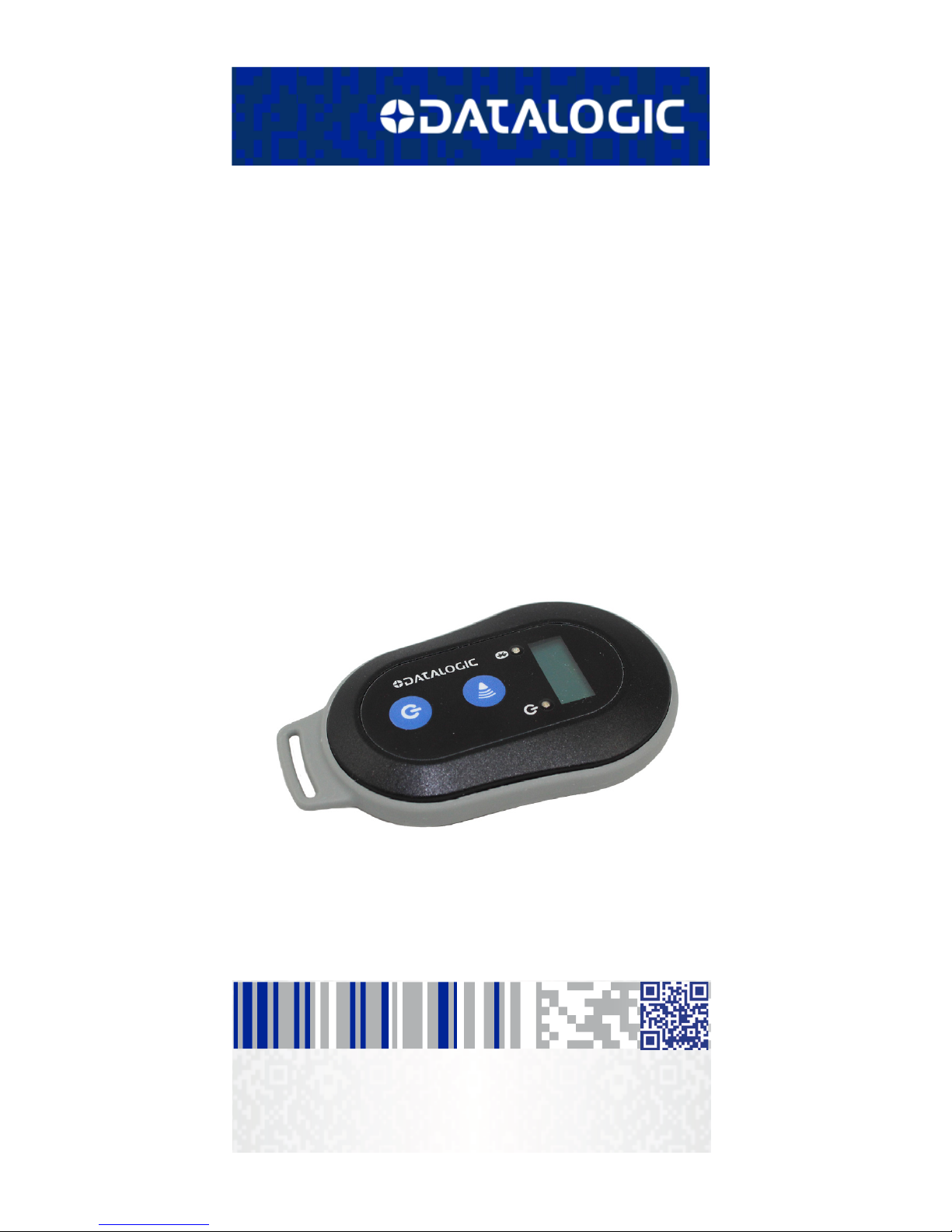
DLR-BT001-xx Family
RFID UHF Bluetooth® Pocket Reader
EU/US
Product Reference Guide
Page 2

Datalogic S.r.l.
Via San Vitalino 13
40012 Calderara di Reno (BO)
Italy
Telephone: +39 051 3147011
Fax: +39 051 3147288
©2017 Datalogic S.p.A. and/or its affiliates
• All rights reserved. • Without limiting the rights under copyright, no part of this documentation may be reproduced,
stored in or introduced into a retrieval system, or transmitted
in any form or by any means, or for any purpose, without the
express written permission of Datalogic S.p.A. and/or its affiliates ("Datalogic"). Owners of Datalogic products are hereby
granted a non-exclusive, revocable license to reproduce and
transmit this documentation for the purchaser's own internal
business purposes. Purchaser shall not remove or alter any
proprietary notices, including copyright notices, contained in
this documentation and shall ensure that all notices appear
on any reproductions of the documentation.
Should future revisions of this manual be published, you can
acquire printed versions by contacting your Datalogic representative.
Electronic versions may either be downloadable from the Datalogic website (www.datalogic.com) or provided on appropriate media. If you visit our website and would like to make
comments or suggestions about this or other Datalogic publications, please let us know via the "Contact Datalogic" page.
Disclaimer
Datalogic has taken reasonable measures to provide information in this manual that is complete and accurate, however,
Datalogic reserves the right to change any specification at any
time without prior notice.
Datalogic and the Datalogic logo are registered trademarks of
Datalogic S.p.A. in many countries, including the U.S.A. and
the E.U.
DLR-BT001-XX is a trademark of Datalogic S.p.A. and/or its
affiliates. The Bluetooth word mark and logos are owned by
Bluetooth SIG, Inc. and any use of such marks by Datalogic
Group companies is under license. All other trademarks and
brands are property of their respective owners.
Page 3

Product Reference Guide i
Table of Contents
RFID Reader DLR-BT001 .................................................... 1
General Information ........................................................................ 1
General Features ............................................................................. 2
Using the DLR-BT001 ..................................................................... 2
Front Panel Description ........................................................ 4
Acoustic and Vibration ..........................................................5
Charging the Battery ......................................................................5
USB Connector ........................................................................6
Not Removable Battery .........................................................6
Accessories ...................................................................................... 6
Disposal of the Product .................................................................. 7
Technical Specifications ................................................................. 8
Reader-Tag Link Profiles ................................................................ 9
Radiation Patterns ........................................................................10
Model – EU (ETSI) ........................................................ 10
Model – US (FCC) ......................................................... 11
Getting Started.................................................................. 13
Introduction ...................................................................................14
Using DLR-SW Profile ...................................................................15
Display Options in the DLR-SW Profile ......................................19
Reader-Host Communication Setup: Possible Cases ...............21
Options List in the HID Profile .....................................................29
FORMAT ....................................................................... 29
DISPLAY ....................................................................... 30
APPLEKB...................................................................... 30
Using BUFFER Profile....................................................... 31
Resetting the DLR-BT001-XX Reader ........................................32
DLR-BT001-XX Configuration
of Main Menu & Aux Menu.............................................. 33
Introduction ...................................................................................33
PROFILE ....................................................................... 34
BEEP............................................................................. 35
VIBRATE ....................................................................... 36
POWER......................................................................... 37
CLOCK........................................................................... 37
Firmware Upgrade ............................................................ 39
Datalogic Limited Factory Warranty ...........................................41
Services and Support ....................................................................44
Page 4

ii RFID Bluetooth® Pocket Reader DLRBT001
NOTES
Page 5
Product Reference Guide 1
RFID Reader DLR-BT001
General Information
The DLR-BT001-XX is a feature-rich hand-held UHF RFID
Reader. It is available in two different models to fit the different frequency standards in the EU and US regions.
The reader is compliant with UHF RFID ISO 18000-63 and
EPC Class 1 Gen 2 standards. The reference document is:
"EPC Radio-Frequency Identity Protocols Generation-2
UHF RFID", Protocols for Communications at 860MHz960MHz, Version 2.0.1 (April 23, 2015).
The DLR-BT001-XX has an integrated antenna suited for
short to medium range applications. Thanks to the Bluetooth® communication interface, it is a perfect UHF RFID
add-on for any Bluetooth® enabled host such as a PC, a
smartphone, a PDA or a tablet. The reader is compatible
with Windows XP/7/8/8.1, Windows CE/Mobile and
Android. A micro-USB connector conceived mainly for
power recharge purposes, is also a useful communication
interface.
The reader can also operate in “Buffer Mode”, allowing to
store EPC codes into the internal memory when the communication links (USB or Bluetooth®) are not available.
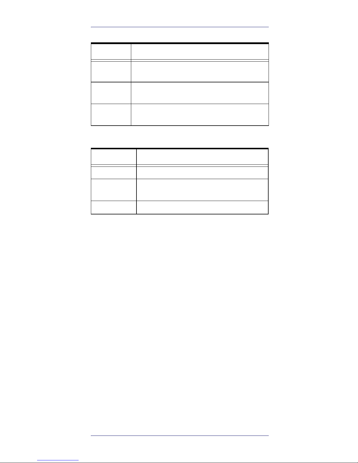
Table 1- Models P/N
MODEL P/N RF carrier freq
DLR-BT001-EU
865.6 ÷ 867.6 MHz
DLR-BT001-US
902.0 ÷ 928.0 MHz
WARNING
The battery is not initially fully charged.
Charge it before use. See
Charging the
Battery on page 5
.
Page 6

RFID Reader DLR-BT001
2 RFID Bluetooth® Pocket Reader DLRBT001
General Features
The DLR-BT001-XX supports a Bluetooth® native keyboard emulation allowing to interact directly with legacy
application, office automation SW or any other generic
solution requiring manual input. When paired to a smartphone or to a tablet, the Device is a cost-effective alternative to more expensive handheld devices. Designed for
mobile operators in indoor or outdoor
1
areas, DLR-BT001XX is ideal for in-store inventory management, field sales
mobility, service & maintenance applications.
The device easily performs the reading of a population of
UHF Tags being located in its proximity and preferably in
front of it.
When the Host / Reader Link is not available, the reader is
able to operate in "Buffer Profile", allowing the storage of
EPC codes into its internal memory for a later download.
Special attention has been given to minimize the current
consumption and extend battery duration by limiting the
active reading time.
A USB connection is mainly dedicated to battery charge,
but could act as an auxiliary virtual com port (VCP) useful
during setup, configuration and downloading actions.
Using the DLR-BT001
The DLR-BT001-XX is a hand-held UHF RFID reader with
integrated antenna. The reader can send EPC codes to a
PC, tablet or smartphone via USB or Bluetooth. The
reader’s front panel is the user interface.
1. Pay attention to the weather conditions because the
device is not waterproof.
Page 7
RFID Reader DLR-BT001
Product Reference Guide 3
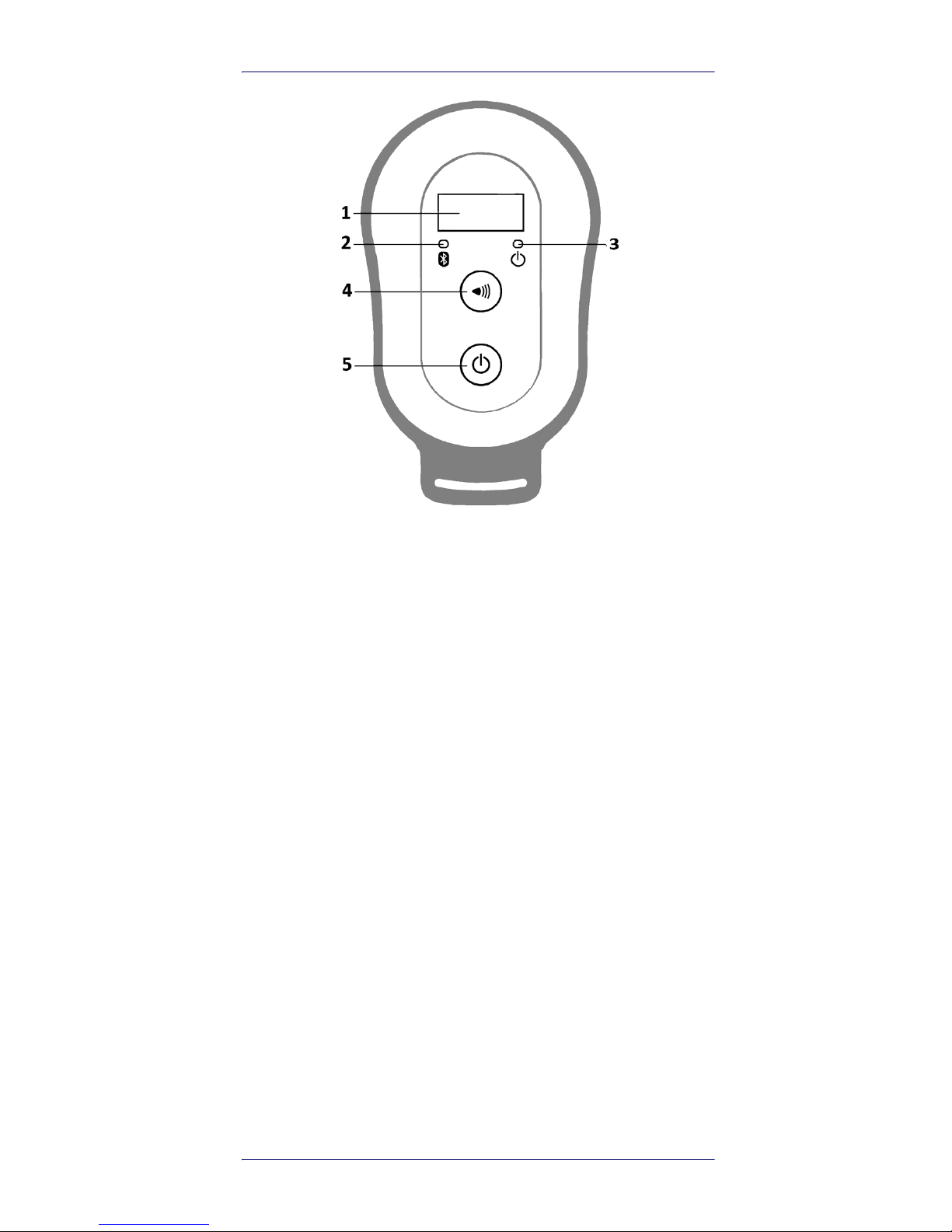
Figure 1. DLR-BT001-XX Front Panel
Page 8
RFID Reader DLR-BT001
4 RFID Bluetooth® Pocket Reader DLRBT001
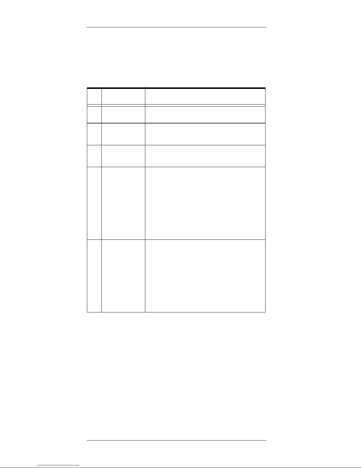
Front Panel Description
The front panel is illustrated in Figure 1. on page 3and its
five main features are described in the table below:
Table 2- Front Panel LEDs and Buttons
N° Name Description
1
Display LCD Alphanumeric Display (8 chars x 2 lines).
2
Link LED
Indicates the Bluetooth® and USB/charger
connection (refer to
Table 4 on page 5
).
3
Power LED
Indicates the reader status and battery level
(refer to
Table 3 on page 5
).
4
Trigger Button
In Inventory mode: press it shortly to perform a single inventory cycle (hold it down to
repeat multiple inventory cycles).
From initial ON state: press it within 2 seconds to enter the Main Menu Mode.
In Menu mode: quick press it to scroll. Hold
down for a few seconds to activate the
option displayed.
5
Power Button
From OFF: Press it to switch the reader ON.
From initial ON state: press it shortly to
enter the second Aux Menu Mode (Format Display Option settings).
From ON: hold down for more than 2 seconds to switch the reader OFF
a
.
In Menu modes: press to return to the Main
Menu.
a. Only in DLR-SW or HID profiles.
Page 9
RFID Reader DLR-BT001
Product Reference Guide 5
Table 3- Reader Power LED Status Table
Table 4- Reader Bluetooth LED Status Table
Acoustic and Vibration
Two events signaling resources complete the User Interface:
•Two tones Buzzer
•Vibrator.
Charging the Battery
The DLR-BT001-XX unit is supplied with a USB cable you
can connect to a PC with a USB host port or to a 5 V power
supply (with USB output).
When you put the reader in charge, the display lights up
and shows the blinking charge indicator. A fixed indication
"charge 100%" informs you when the charge is complete.
Status Description
Green
Reader is active and the battery charge is in the
range of 35÷100%.
Orange
Reader is active and the battery charge is in the
range of 15÷35%
Red
Reader is active and the battery charge is in the
range of 0÷15%
Status Description
OFF No Connection established
Orange
USB Cable connected (either to a PC or to the AC
adapter)
Blue Bluetooth® connected
Page 10
RFID Reader DLR-BT001
6 RFID Bluetooth® Pocket Reader DLRBT001
USB Connector
A micro USB Type B socket connector is located in the bottom side of DLR-BT001-XX. It can be used to connect the
reader to a USB host port or to a AC/DC battery charger.
Not Removable Battery
Due to its nature and dimensions, DLR-BT001 has a fixed
rechargeable battery. It is strictly forbidden to remove it
for charging or any other purpose. The charge will be performed using exclusively the micro USB connector.
Accessories
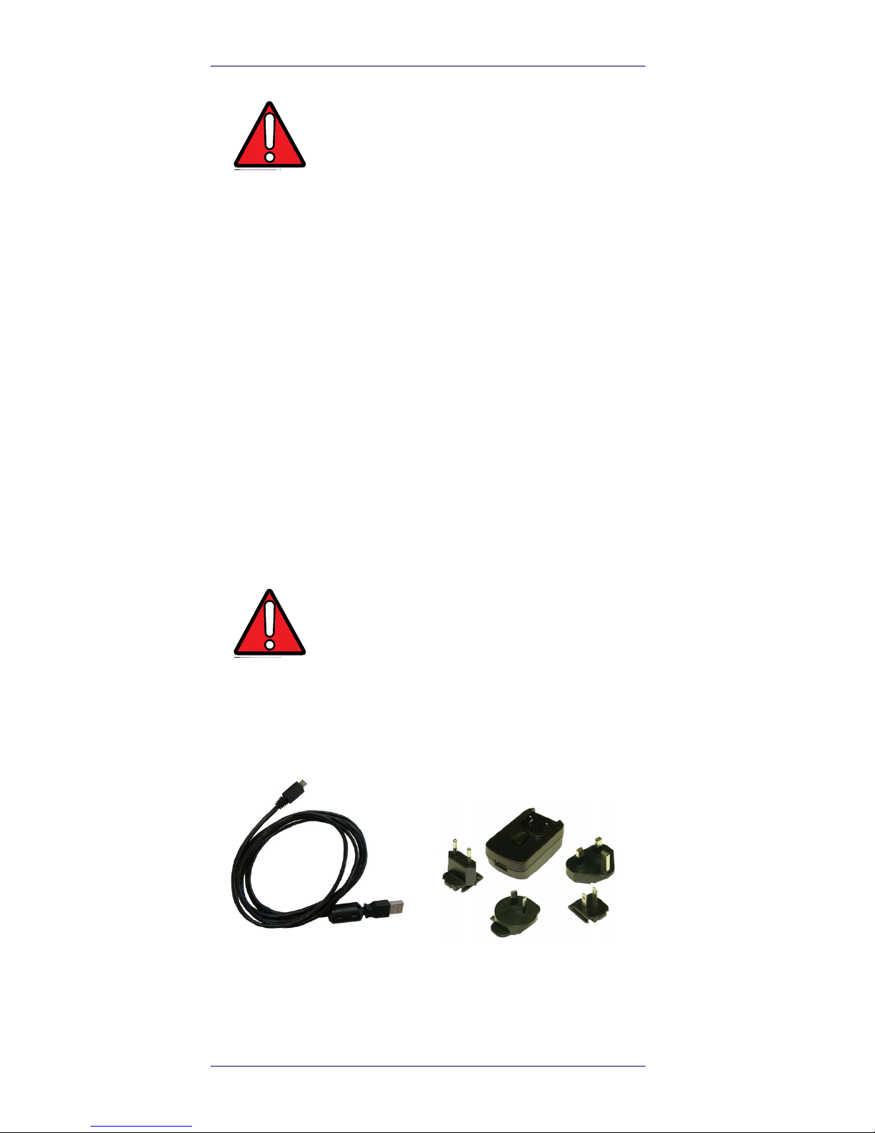
Figure 2. Set of Accessories (Delivered with DLR-BT001)
WARNING
If the battery is completely low, the display
may not turn on when the charger is
connected. In this case, leave the reader
connected to the charger for at least 5
minutes; then disconnect the USB cable and
perform the reset procedure described in
Resetting the DLR-BT001-XX Reader on
page 32
). Switch off the reader by pressing
the power button and then connect the USB
cable again.
WARNING
Any attempt to access or replace the battery
will cause an infringement of the warranty.
In case of battery malfunction, please call
Datalogic technical assistance.
No. 1 B to A Type Micro USB
cable
No. 1 Power supply
Page 11
RFID Reader DLR-BT001
Product Reference Guide 7
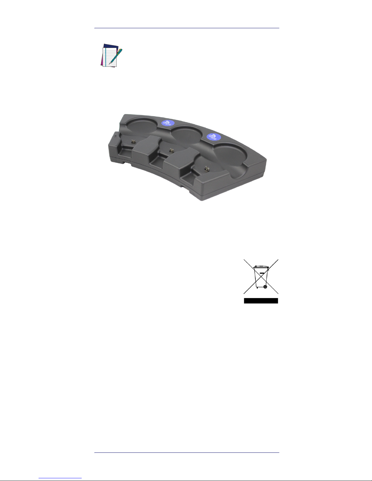
Figure 3. Multi Charger Unit or Docking Station
Disposal of the Product
Do not dispose the product in municipal or
household waste. Please check your local
regulations for disposal/recycle of electronic
products.
NOTE
An additional Power Supply unit named: “Multi
Battery Charger” with Code MBC-DLRBT001is
available, too (to be ordered separately). See Figure 3 below. For full details, refer to the MBCDLRBT001 PRG, downloadable from the Datalogic
Website.
Page 12
RFID Reader DLR-BT001
8 RFID Bluetooth® Pocket Reader DLRBT001
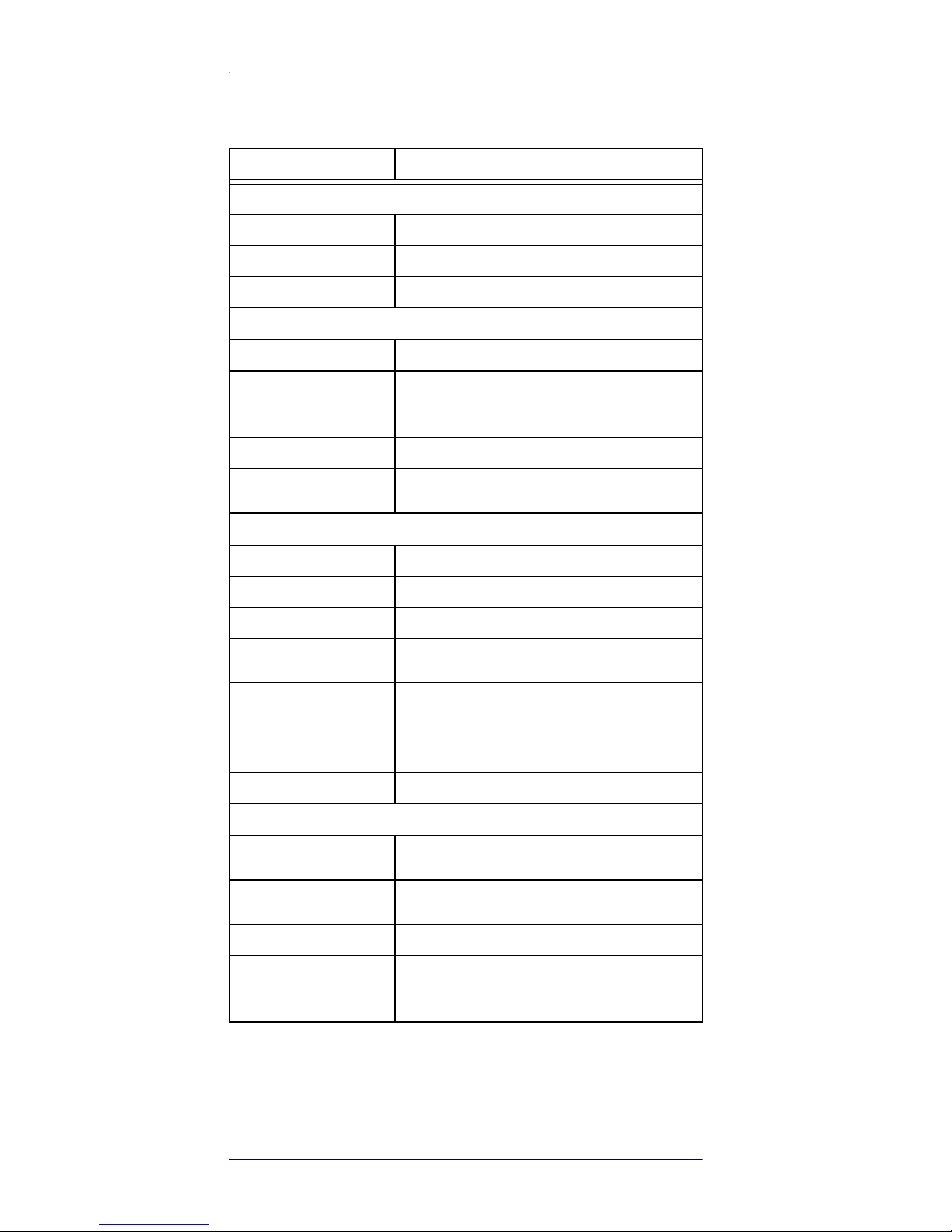
Technical Specifications
Item Description
Physical Characteristics
Reader Dimension
9.9 x 5.4 x 2.0 cm3 / 3.9 x 2.1 x 0.8 in
3
Length of USB Cable
1.5 m / 4.9 ft
Weight
57 g / 2.0 oz
Electrical Characteristics
Battery
Battery Type: Li-Ion 3.7V, 570 mAh
Battery Life
Operating: >12 hours with 40,000 tag readings;
Standby: 15 days
Battery Charging Time
2 hours (typical)
Internal Buffer Size
64kByte (equiv. to 5300 ASCII EPC codes or
2650 HEX codes)
Reader - Tag Link
Type
UHF - RFID
Antenna
Integrated linear (horizontal)
Standard Compliance
ISO 18000-6C/EPC C1G2
Frequency Range
865.60÷867.60 MHz - European standard
902.00÷928.00 MHz - US standard
RF Power
Programmable in 18 levels from 5 dBm
e.r.p.
(3 mW e.r.p.) to 22 dBm e.r.p. (150 mW
e.r.p.)
Reading Range
Up to 90 cm / 35.4 in
Reader - Host Link
Type
Bluetooth® (wireless)
USB (corded)
Bluetooth®
Class 2 with output power 4dBm e.i.r.p.
Bluetooth ver. 2.1 freq.2.4 Ghz.
USB
USB 2.0 Full Speed (12 Mbit/s) device port
Virtual COM Port
Baudrate: 115.200 kbps;
Databits: 8; Stopbits: 1
Parity: none; Flow control: none
Page 13
RFID Reader DLR-BT001
Product Reference Guide 9
Reader-Tag Link Profiles
The DLR-BT001-XX readers support different modulations
and return link profiles according to EPC Class1 Gen2 protocol V.2.0.
All profiles that have been tested for compliance with the
European and US regulations are reported in the following
table:
Table 5- DLR-BT001-XX Reader to Tag link profiles
Item Description
User Environment
Particulate and Water
Sealing
IP40
Operating
Temperature
0° to 45°C / 32° to 113°F
Storage Temperature
-20° to 60°C / -4° to140°F
P Regulation Modulation Return Link
0
ETSI – FCC PR–ASK; f=40kHz FM0; f = 40kHz
1
ETSI – FCC PR–ASK; f=40kHz Miller (M=4); f = 256kHz
2
ETSI – FCC PR–ASK; f=40kHz Miller (M=4); f = 320kHz
Page 14
RFID Reader DLR-BT001
10 RFID Bluetooth® Pocket Reader DLRBT001
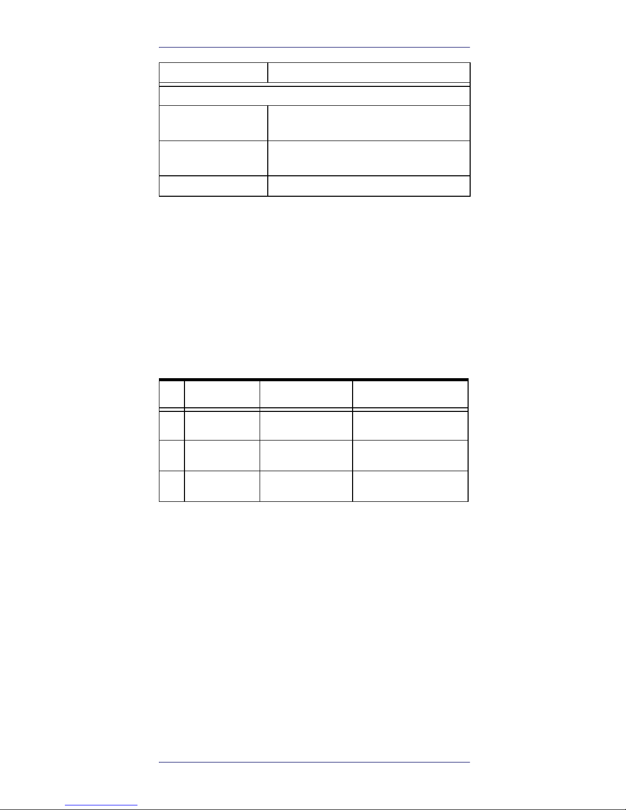
Radiation Patterns
The radiation patterns of DLR_BT001-XX are shown in the
following figures:
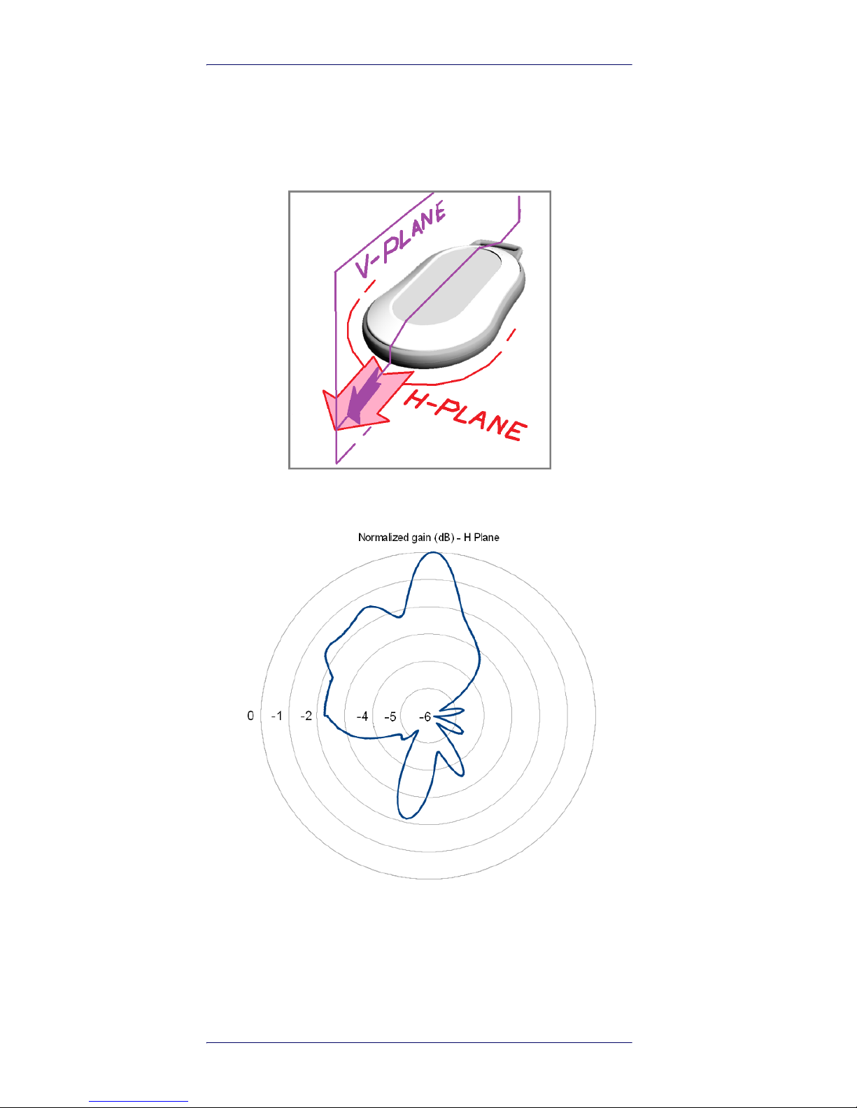
Model – EU (ETSI)
Figure 4. EU Radiation Pattern H Plane
Page 15
RFID Reader DLR-BT001
Product Reference Guide 11
Figure 5. EU Radiation Pattern V Plane
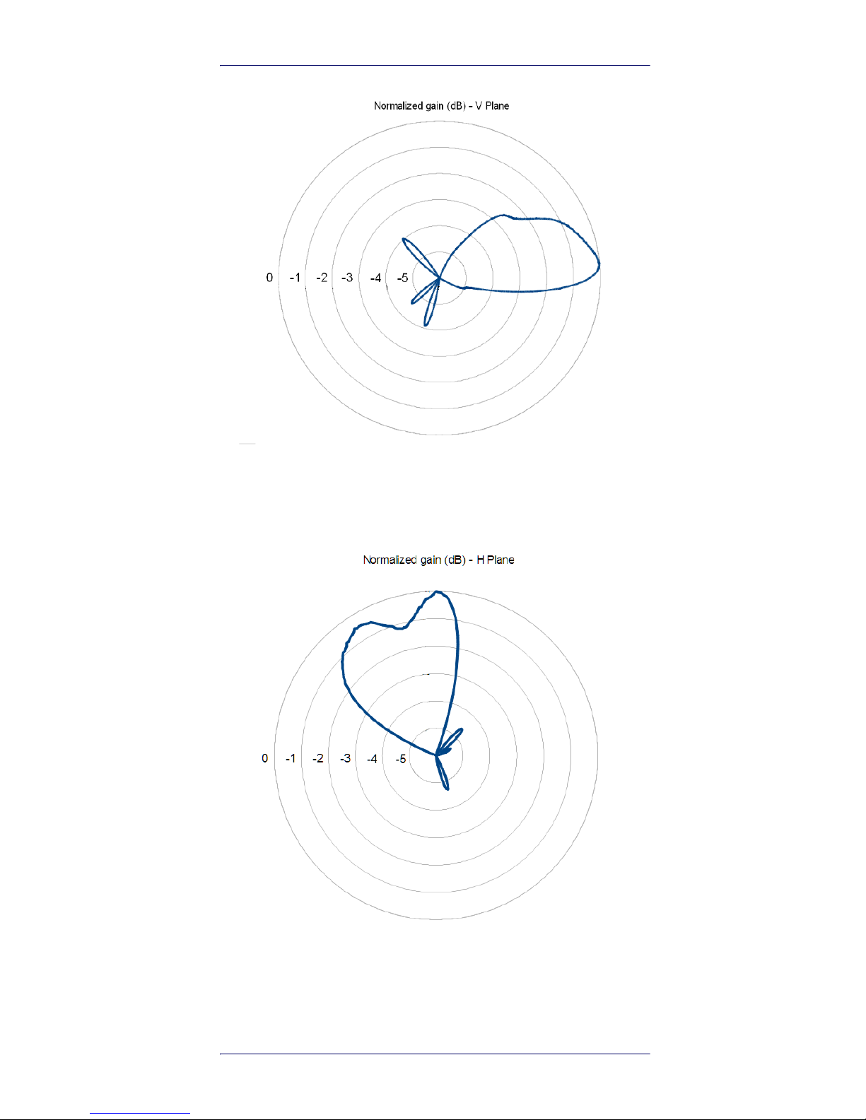
Model – US (FCC)
Figure 6. US Radiation Pattern H Plane
Page 16

RFID Reader DLR-BT001
12 RFID Bluetooth® Pocket Reader DLRBT001
Figure 7. US Radiation Pattern V Plane
Page 17

Product Reference Guide 13
Getting Started
The reader can be connected to almost all devices supporting the Bluetooth® HID profile (keyboard emulation):
tablets, smartphones, Windows-PC, Android devices, iOS,
etc.
To move the first steps and get familiar with the product
you will need:
• n. 1 DLR-BT001-XX UHF RFID reader (XX = EU or US)
with its own accessories (micro type B USB cable and
supply unit).
• n. 1 set of labels (few low cost passive UHF Tag
labels)
• n. 1 DLR-TL001 Temperature Logger Tag: a”semipassive” (battery-powered) unit communicating as a
Tag but having some more complex features and
data handling capabilities. It is not strictly necessary
for an elementary learning approach. Read the NOTE
below.
SW tools fully covering the needs for the matching
reader’s standard (ETSI/EU or FCC/US) and specific documentation (Quick Start Guide) can be found in the Datalogic website.
NOTE
The Temperature Logger Tag is a battery powered
element able to sample alone the temperature
history of the accompanying good/s. The data
exchange with the reader is more complex. This
kind of tag has a much wider memory, it is programmable (in particular its sampling time could
be customized and optimized to get an “as low as
possible power consumption”). The structure of
the antenna circuit interface to the UHF RFID
reader is the same as in the passive tags, working
with the same link profile. A sample is given in
Figure 8. on page 14
It is named “semi-passive” unit due to its merge
of the passive antenna circuit interface and the
low consumption active temperature processor.
Page 18

Getting Started
14 RFID Bluetooth® Pocket Reader DLRBT001
Figure 8. Temperature Logger Tag - DLR-TL001
Introduction
The Product Reference Guide will help you to get started
with your DLR-BT001-XX reader model.
The Reader has two communication interfaces: Bluetooth® and USB. Bluetooth® is the main interface and it
uses the SPP profile (Serial Port Profile or HID), while the
USB interface is mainly used for battery charging and
firmware updating.
The reader has a default configuration that enables the
Bluetooth® communication at power-on only with cable
disconnected. The unit is ready to accept connection
requests (discoverable) coming from most of the Bluetooth® enabled hosts.
At power on a DL–RFID logo is displayed for few seconds.
About communication protocol, the reader has three alter-
native profiles: DLR-SW, HID or BUFFER. They are selectable through a configuration menu.
The reader’s configuration menu is widely described in
DLR-BT001-XX Configuration of Main Menu & Aux Menu
on page 33. The HID profile is the reader’s factory default
profile:
• HID: choose this option to select the keyboard emulation protocol. For details on the use of the HID profile
please refer to Options List in the HID Profile on page
29.
• BUFFER: choose this option when host connection is
not available. The EPC data will be stored into the
reader's internal memory for a later download to the
Page 19

Getting Started
Product Reference Guide 15
host. When using BUFFER, please refer to chapter
Using BUFFER Profile on page 31.
•This guide helps you to get started with your reader
using the DLR-SW profile (over Bluetooth®, with
SPP).
The following table lists the allowed “Profiles – OpSys”
choices for DLR-BT001-XX:
Table 6- Compatibility between Profiles and primary OpSys
The following description is the first detailed communication setup case that uses a typical condition.
Using DLR-SW Profile
1. Download the proper SW controller from the DL
website: A DLR-SW RFID Software Tool Controller
for Android Application can be found in the DLRBT001-XX webpage by clicking on the Android APP
on the Google Play icon.
2. Launch DLR-SW RFID Software Tool Controller for
Android App. The following screen is displayed:
<OS - PROFILE> DLR-SW HID BUFFER
ANDROID (Tablet)
√√√
WINDOW (PC)
√√√
iOS (Ipad or Iphone)
-
√
-
Page 20

Getting Started
16 RFID Bluetooth® Pocket Reader DLRBT001
3. Click on “Add Reader”; the next screen lists the
allowed connection types:
4. Click on “Bluetooth” in the “Connection Type” window; the next screen asks for a confirmation:
Page 21

Getting Started
Product Reference Guide 17
5. Click on “yes” to accept the Bluetooth permission
request; the next screen displays the sensed
device(s)/reader(s):
6. Select your DLR-BT001 reader from the list of Bluetooth® devices; the next screen asks for a passkey
confirmation:
7. Confirm the passkey.
8. Once the connection is established, the Bluetooth®
blue led turns on, the Bluetooth® link goes active
and the screen displays the sensed reader’s name
DLR-BT001-XX. See the figure below:
Page 22

Getting Started
18 RFID Bluetooth® Pocket Reader DLRBT001
9. To start using your DLR-BT001-XX, click on the
reader line; the following screen invites you to start
a search/inventory cycle of the tags being reachable all around the reader.
10. Click on “Start Inventory”; A list of sensed tags is
shown, as in the example below:
Page 23

Getting Started
Product Reference Guide 19
The listed sensed tags are normally located in a short to
medium distance range (up to 50 cm from the reader).
The tags must be compatible with the reader’s protocol
specification. This is the case of the accompanying delivery tag samples.
Display Options in the DLR-SW
Profile
To enter the Display profile options, turn on the reader; the
display shows information on the currently active profile
(DLR-SW) and then the message "ready" informs you that
the reader is operating. Press quickly the power button to
enter the DLR-SW Display profile option.
Hold down the trigger button to enter the Display Option:
• CONTROL: Hold down the trigger button to enter the
CONTROL options:
- LOCAL: the DLR-BT001-xx display shows the
EPC of the read tags.
- REMOTE: the display is controlled by a PC, a
smartphone etc. using the function PrintScreen.
So with this option you can customize the information displayed by the reader about the read
tags (e.g., instead of the EPC you can display
messages such as "correct tag").
Use the function PrintScreen (for more information, visit the Datalogic RFID SDK Software
Page 24

Getting Started
20 RFID Bluetooth® Pocket Reader DLRBT001
Development Kit web page and download the
Datalogic RFID API Reference Manual) to customize the information displayed by the reader:
C# representation:
public void PrintScreen(
string Text,
string TerminalType
)
Parameters:
Name Description
Text An arbitrary ASCII string.
TerminalType
RFU parameter, default is 0
(VT100).
Page 25

Getting Started
Product Reference Guide 21
The currently active CONTROL is marked with an asterisk.
To activate a different CONTROL, scroll the CONTROL
options by pressing quickly the trigger button until LOCAL
or REMOTE is displayed. Hold down the trigger button for
a few seconds: the name of the chosen option will begin to
flash. Once activated, the device returns to the main
menu.
By default the CONTROL is set to LOCAL.
Reader-Host Communication
Setup: Possible Cases
The previous Setup example is one of the possible alternatives, but others setup are possible.
The communication between the reader and the host varies depending on:
•The Profile
• The Operating System and the selected Host running
it
The USB with VCP emulation can be used for the readerhost communication: VCP with USB is equivalent to SPP
with Bluetooth®.
The most frequent setup alternatives are reported in the
table below:
Table 7- DLR-BT001-XX – Communication Setups
CASE INTERFACE PROFILE OPERATING SYSTEMS
1 BT (/SPP) DLR-SW ANDROID (Tablet, PDA, etc)
2 BT (/SPP) DLR-SW WINDOW (PCs with BT)
3 USB (/VCP) DLR-SW WINDOW (PCs with USB)
4 BT HID (kb-emu) ANDROID (Tablet, PDA, etc)
5 BT HID (kb-emu) WINDOW (PCs with BT)
6 BT HID (kb-emu) iOS (iDev with BT)
Page 26

Getting Started
22 RFID Bluetooth® Pocket Reader DLRBT001
Case N° 1 BT – DLR-SW – ANDROID
This is the first setup example given before.
Case N° 2 BT – DLR-SW – WINDOW
In this example a Win 8 OS is intended to be running on a
PC:
1. Right click on the Bluetooth icon in the taskbar >
“Add a Bluetooth Device”:
2. Select the DLR-BT001-XX reader and click on “Pair”:
a passcode confirmation is asked:
Page 27

Getting Started
Product Reference Guide 23
3. Click “yes” to confirm the passcode.
In the case of a Win XP OS, when discovered by the host,
your DLR-BT001-XX reader can be identified by its Bluetooth® device name, then paired using the pass-key; both
parameters are provided here below:
• BT device name: “DLR-BT001“+ device serial number
• Pass-key: 1234
4. Once the connection is up, the Bluetooth® blue LED
turns on.
Now you can use the DL RFID Software Controller Application to control the reader. The application could be downloaded from the Datalogic website at the DLR-BT001-XX
web page. Check the latest version of DL RFID Software
Tool Controller for Windows software and install it. Refer
to the manuals downloadable from the website to complete the needed steps.
Case N° 3 USB – DLR-SW – WINDOW
The reader can be connected to a PC using the provided
USB cable and it could be detected by the PC as an emulated serial port (VCP). In order to correctly operate with
the reader you need to install a driver on the PC. Let’s
refer to a Win 8 Operating System.
1. Power ON the reader and plug the USB cable into
the DLR-BT001-XX USB port.
2. In order to connect your reader to the PC you need
to install the VCP (Virtual Com Port) drivers for your
specific operating system version. You can down-
Page 28

Getting Started
24 RFID Bluetooth® Pocket Reader DLRBT001
load VCP drivers for Windows based systems from
the Datalogic RFID Website, in the SW/FW section.
3. Open the System properties: go to “Control Panel “>
“All Control Panel Items” > “System” and click on the
option “Device Manager”.
4. After installing the driver, the reader is detected by
the PC (in the Device Manager window) as an emulated serial port (VCP).
Once the connection is up, the USB Yellow LED turns on.
Now you can use the DL RFID Software Tool Controller
Application to control the reader under the DLR-SW profile. The application could be downloaded from the Datalogic website, at the DLR-BT001-XX web page. Check for
the latest version of this application, download and install
it. Refer to the manuals downloadable from the website
to complete the needed steps.
Cases N° 2 & 3: DLR_SW for Windows - activation finish
up
Both USB and Bluetooth® interfaces create a virtual COM
port (VCP /SPP) on the host PC that can be used to connect to the reader by running a Windows type of the “DL
RFID Software Tool Controller” Application.
Page 29

Getting Started
Product Reference Guide 25
The activation of this version of DLR-SW profile is required
to connect the DLR-BT001-XX in the case of Windows O.S.
Follow the steps below to connect the reader using DLRSW Controller for Windows via Bluetooth® (or via USB connection):
1. Download from the DLR-BT001-XX web page the
latest SW version of the DL RFID Software Tool Controller for Windows software and install it.
2. Connect the DLR-BT001-XX reader to the PC using
either the Bluetooth® connection or the USB connection.
3. Right click on the Bluetooth® icon in the taskbar
>Open Settings (as for USB, please refer to the “System > Device Manager” path in the previous figure):
4. Look for the emulated serial COM port number in
the “Bluetooth Settings” (example: COM10) or, in
case of USB, under the “Device Manager” (example:
COM4).
5. Launch the application you downloaded at point 1.
6. On the application main window, click on “File” >
“Connect”; the connection dialog box will appear.
7. Select RS232 from the Connection Type combo box
and the right COM <port number> from the RS232
Port combo box.
8. Click on “Connect”.
Page 30

Getting Started
26 RFID Bluetooth® Pocket Reader DLRBT001
9. Now the application is ready to accept a command /
click on “Start Inventory” to display the information
of the detected tags on the main window.
For more information on the DL RFID Software Tool Controller for Windows application usage, please refer to the
relevant user manual: you can download it from the DLRBT001-XX webpage, Documents Section, or in the web
area named Manuals and Documents.
A DL RFID Software Tool Controller for Android application
is also available. For more information please refer to the
DL RFID Software Tool Controller for Android web page.
Case N° 4 BT – HID – ANDROID
This is the configuration case when using the HID (keyboard emulation protocol) Profile for a Bluetooth® link,
while the host is an ANDROID operated machine.
1. On your Android device, go to the Setting Box and
enable the Bluetooth®. A list of the Bluetooth®
available devices is shown:
2. Click on the selected DLR-BT001-XX reader and
complete the pairing/passkey-OK steps.
3. Once the connection goes up, the Bluetooth® blue
LED turns on.
4. Launch a Text Edit App (or any other App with keyboard input).
5. Start an “inventory cycle” by pressing the trigger
button.
Page 31

Getting Started
Product Reference Guide 27
6. On the text editing App window you will see the
EPCs of the tags:
Case N° 5 BT – HID – WINDOW
This is the configuration case when using the HID (keyboard emulation protocol) Profile for a Bluetooth® link,
while the host is operating under WINDOWS OS. As a
working example a WIN 8 version is considered.
The first 4 steps (up to “blue LED turns on”) are exactly the
same as in the Case N° 2 BT – DLR-SW – WINDOW on
page 22.
4. Once Bluetooth® link is established, blue LED turns
on.
5. Launch a text editing application (or any other application/ program accepting a keyboard input: Notepad is OK).
6. Start an “inventory cycle” by pressing the reader’s
trigger button.
7. On the text editing window you will get the tag
EPCs.
NOTE
When configured in HID profile and paired to a
device, the reader DLR-BT001-XX will automatically reconnect to the same device every time the
Bluetooth® link is active (Reader switched ON and
Bluetooth® activated on the host). This behavior
can be verified looking at the blue LED that, in this
case, automatically turns ON as soon as you
switch on the reader.
Page 32

Getting Started
28 RFID Bluetooth® Pocket Reader DLRBT001
Case N° 6 BT – HID – iOS
This is the configuration case when using the HID (keyboard emulation protocol) Profile for a Bluetooth® link,
and the host is an iOS operated machine.
1. On your iOS operated host go to Settings and enable
the Bluetooth®.
2. A list of the Bluetooth available devices is shown.
3. Click on the DLR-BT001-XX reader in the list you
want to link up. Perform pairing and passcode confirmation for it.
NOTE
When configured in HID profile and paired to a
device, the DLR-BT001-XX will automatically
reconnect to the same device every time the Bluetooth® link is active (Reader switched ON and
Bluetooth® activated on the host). This behavior
can be verified looking at the blue LED. In this
case, it automatically turns ON as soon as you
switch on the reader.
Page 33

Getting Started
Product Reference Guide 29
4. As soon as the connection is established the Bluetooth® blue LED turns on.
5. Launch a Text Editing App (or any other App accepting a keyboard input).
6. Start an inventory cycle by pressing the reader’s
trigger button.
7. On the text editing window you will find the EPCs of
the detected tags:
Options List in the HID Profile
To enter the HID profile options, turn on the reader, the
display shows information on the currently active profile
(HID) and then the message "ready" informs you that the
reader is operating. Press quickly the power button to
enter the HID profile options:
•FORMAT
•DISPLAY
• APPLEKB
FORMAT
In the HID profile you can set different EPC format, while
by using the DLR_SW profile it is not possible to change
the HEXADECIMAL EPC format.
• HEX: the RFID EPC string (96 bits long) is displayed as
24 hex characters (4 bits per character).
• ASCII: the RFID EPC string (96 bits long) is displayed
by 12 ASCII characters.
The currently active format is marked with an asterisk. By
default the EPC HID format is set to “HEX”.
To activate a different format, scroll the FORMAT options
by pressing quickly the trigger button until HEX or ASCII is
displayed. Hold down the trigger button for a few seconds,
Page 34

Getting Started
30 RFID Bluetooth® Pocket Reader DLRBT001
the chosen option will begin to flash. Once activated, the
device returns to the main menu.
DISPLAY
Hold down the trigger button to enter the Display Option:
1. SCROLL: Flowing text on display. To enable/disable
the display scroll, hold down the trigger button for a
few seconds. The chosen option will begin to flash.
Once activated, the device returns to the main
menu.
The currently active state is marked with an asterisk. By
default the display scroll is disabled and the display
shows the last 8 characters of the tag EPC.
If the display scroll is enabled, the flowing text on the display shows the whole EPC of the tag.
APPLEKB
Hold down the trigger button to send a request to iOS
device paired with the reader to open the virtual keyboard
on the iOS device.
Page 35

Product Reference Guide 31
Using BUFFER Profile
The Buffer profile can be used when the communication
links (USB or Bluetooth) are not available, for example in
case of temporary missing of bluetooth communication.
The operator can collects EPC codes, the reader store data
into the internal buffer. When the BT link is up, or a USB
cable is connected, the reader can send the buffered data
if requested by the host.
For details on the activation method please refer to PRO-
FILE on page 34.§
To perform the tag inventory, hold down the trigger button.
The display shows the number of read tags and information about memory used/total memory.
Example:
TAGS 018
02K/64K.
See DISPLAY on page 30§.
Now, the reader can be connected to the host through
USB cable or bluetooth.
Please refer to case nr.1 or case nr.2 for instructions to
connect bluetooth.
Please refer to case nr.3 for instructions to connect USB.
Download Data
When the reader is connected to the USB cable or Bluetooth to a PC or Android device, it is possible to download
buffered data using proprietary DL SDK (refer to: "DL RFID
API User Manual" and "DL RFID API Reference Manual").
Page 36

Using BUFFER Profile
32 RFID Bluetooth® Pocket Reader DLRBT001
Resetting the DLR-BT001-XX
Reader
Remind the Reader’s Front Panel at Figure 1. on page 3:
To reset the reader, press simultaneously power and trigger buttons for about six seconds, then release them.
The reader will restart and restore to the “Default State”.
WARNING
Note that the reader SHALL NOT be
connected to the USB port or to the battery
charger during this reset action, otherwise
the reader enters in the “firmware upgrade
state”.
If, by mistake, you enter the “firmware
upgrade state”, disconnect the USB cable
and repeat the reset procedure to restore
the normal reader operation.
Page 37

Product Reference Guide 33
DLR-BT001-XX Configuration
of Main Menu & Aux Menu
Introduction
To access the MAIN MENU, turn on the device (power) and
hold down the trigger button within two seconds. To scroll
the main menu, press quickly the trigger button.
The DLR_BT001’s configuration menu options are the following:
•PROFILE
• BEEP
•VIBRATE
•POWER
•CLOCK
To select a menu option, hold down the trigger button.
The complete structure of the DLR-BT001-XX reader’s
main menu is summarized in Figure 9. on page 34.
The menu and sub-menu items in the figure can be seen
on the double lines Reader’s Display during the Configuration Action / Cycle.
Page 38

DLR-BT001-XX Configuration of Main Menu & Aux Menu
34 RFID Bluetooth® Pocket Reader DLRBT001
Figure 9. Reader’s Configuration Menu Structure
PROFILE
The PROFILE menu is the first option of the main menu.
To select it, hold down the trigger button.
Press the trigger button quickly to scroll the PROFILE
options. The currently active profile is marked with an
asterisk.
The PROFILE submenu options are the following:
• DLR-SW: choose this option to select the DL RFID
Software Tool communication protocol. Select this
option to control the reader using the DL RFID Software Tool Controller Application or the SDK (Software
Development Kits) library. For details on the use of
the DLR-SW profile please refer to Using DLR-SW
Profile on page 15.
Page 39

DLR-BT001-XX Configuration of Main Menu & Aux Menu
Product Reference Guide 35
• HID: choose this option to select the keyboard emula-
tion protocol. For details on the use of the HID profile
please refer to Options List in the HID Profile on page
29.
• BUFFER: choose this option to select the stand-alone
mode. The reader stores EPC codes into the internal
memory when the communication links (Bluetooth®
or USB) are not available.
The DLR-SW and HID profiles require the presence of
a nearby host that controls the reader (pc, tablet),
while in the BUFFER profile the reader works in
stand-alone mode.
To return to the main menu, press the power button
quickly.
The currently active profile is marked with an asterisk.
You can activate only one profile at a time.
To activate an alternative profile, scroll the PROFILE
options by quickly pressing the trigger button, until the
desired profile is displayed. Hold down the trigger button
for a few seconds: the profile name will begin to flash.
Once activated, the device returns to the main menu.
When you turn on the reader, the display shows the cur-
rently active profile and then the message "ready" to
inform you that the reader is able to operate.
BEEP
Access the configuration menu as explained in Introduc-
tion on page 33. Press the trigger button quickly to scroll
the menu options.
The BEEP item is the second option of the menu. To select
it, hold down the trigger button.
The BEEP submenu options are the following:
• PWRUP: beep at the power on of the reader
• PWRDOWN: beep at the power off of the reader
• SCANTAG: beep at the identification of a tag
WARNING
Note that if the reader is in the HID profile
you must disconnect it from any connected
device before selecting another profile.
Page 40

DLR-BT001-XX Configuration of Main Menu & Aux Menu
36 RFID Bluetooth® Pocket Reader DLRBT001
To enable / disable the submenu options, scroll the BEEP
options menu by pressing quickly the trigger button until
the desired BEEP option is displayed and then hold down
the trigger button for a few seconds.
Scroll the enable and disable options by pressing quickly
the trigger button and hold down the trigger button for a
few seconds to activate one of them. The enable (or the
disable) option will begin to flash. Once activated, the
device will return to the main menu.
The active state is marked with an asterisk. By default, all
the BEEP options are disabled.
Note that you can enable or disable the beeper independently for any option so that the beeper can be active
simultaneously on more than one option. To return to the
main menu, quickly press power button.
VIBRATE
Access the configuration menu as explained in Introduc-
tion on page 33. Press the trigger button quickly to scroll
the menu options.
The VIBRATE item is the third option of the menu. To
select it, hold down the trigger button.
The VIBRATE sub-menu options are the following:
• PWRUP: vibration at the power on of the reader
• PWRDOWN: vibration at the power off of the reader
• SCANTAG: vibration at the identification of a tag
To enable / disable the submenu options, scroll the
VIBRATE options menu by pressing quickly the trigger
button until the desired VIBRATE option is displayed, then
hold down the trigger button for a few seconds.
Scroll the enable and disable options by pressing quickly
the trigger button and hold down the trigger button for a
few seconds for the activation of one of them. The enable
(or the disable) option will begin to flash. Once activated,
the device returns to the main menu.
The currently active state is marked with an asterisk.
By default, all the VIBRATE options are disabled.
Note that you can enable or disable the vibration inde-
pendently for any option so that the vibration can be
active simultaneously on more than one option. To return
to the main menu, press the power button quickly.
Page 41

DLR-BT001-XX Configuration of Main Menu & Aux Menu
Product Reference Guide 37
POWER
The POWER sub-menu allows to set the RF power level
emitted by the reader.
Note that, when the reader is configured under the DLRSW profile, the power could also be set by using the DL
RFID Software Tool Controller Application or the “Set-
Power” function of the library SDK (Software Development
Kits).
Access the configuration menu as explained in Introduc-
tion on page 33. Press the trigger button quickly to scroll
the menu options.
The POWER sub-menu is the fourth option of the menu.
To select it, hold down the trigger button.
The POWER sub-menu options are the following:
• 25 mW
• 50 mW
• 100 mW
• 200 mW
Press the trigger button quickly to scroll the POWER
options. To return to the main menu, press the power button quickly.
The currently active power is marked with an asterisk.
By default, the 200 mW power level is active.
You can activate only one power level at a time.
To activate a different power level, scroll the POWER
options by pressing quickly the trigger button until the
desired power level is displayed. Hold down the trigger
button for a few seconds: the power level option will begin
to flash. Once activated, the device returns to the main
menu.
CLOCK
The reader does not consider date and time until the first
setting by the user.
To access the CLOCK option, turn off the device and then
turn it on again (power button).
To scroll the menu options, the trigger button press
quickly (hold down the trigger button within two seconds
to enter in the main menu).
Page 42

DLR-BT001-XX Configuration of Main Menu & Aux Menu
38 RFID Bluetooth® Pocket Reader DLRBT001
The CLOCK menu is the last option of the menu. Hold
down the trigger button to select it and enter its submenu.
The CLOCK submenu options are the following:
• Date: the date is the first option of the clock sub-
menu. To set the date, hold down the trigger button
for a few seconds. The date is shown in the format
dd mm yy (e.g. 28 Oct 15). Press the trigger button
quickly to change the day value. Then hold down the
trigger button to save the day and move to the
month value. Press quickly the trigger button to
change the month value. Then hold down the trigger
button to save the month and move to the year
value. Press quickly the trigger button to change the
year value. Then hold down the trigger button to save
the year and hold down again to save the complete
date. The date begins to flash and the reader returns
to the main menu.
• Time: it is the second option of the clock submenu.
Scroll the CLOCK options menu by pressing quickly
the trigger button until the Time option is displayed
and then hold down the trigger button for a few seconds to set the time. The time is displayed in the 24hour format hh:mm (e.g. 14.32). Press the trigger
button quickly to change the hh value. Then hold
down the trigger button to save the hour value and
pass to the minutes value. Press the trigger button
quickly to change the “mm” value. Then hold down
the trigger button to save the minutes value and hold
down again to save the complete time. The time
begins to flash and the reader returns to the main
menu.
To return to the main menu, press the power button
quickly.
Page 43

Product Reference Guide 39
Firmware Upgrade
The DLR-BT001-XX firmware upgrade can be managed via
USB by using the SW Upgrade Program.
The Upgrade Tool is available for free at the DLR-BT001XX web page of the DL RFID Web Site, in the SW/FW section.
To upgrade the firmware, follow the steps below:
1. Connect the reader to the USB port of the PC.
2. Press simultaneously the trigger and the power
buttons for about six seconds.
3. Open the FW upgrade program.
4. Click on “Next”: the next screen will appear:
Page 44

Firmware Upgrade
40 RFID Bluetooth® Pocket Reader DLRBT001
5. In the window you will see the message “Found 1
device” (if the message is “No device connected”
repeat the points 2, 3, 4 and 5).
6. Select the FW image file to be used. Click on
“Browse”.
7. Click on “Upgrade Firmware” and wait for the
upgrade process to be completed.
8. At the end of the procedure, as the upgrade has
been successfully performed, you will see the messages reported in the image below:
Now the module is ready for normal operation.
Page 45

Firmware Upgrade
Product Reference Guide 41
Datalogic Limited Factory Warranty
Warranty Coverage
Datalogic warrants to Customer that Datalogic's products will be
free from defects in materials and workmanship for a period of
one year from product shipment. Datalogic hardware products
are warranted against defects in material and workmanship under normal and proper use. The liability of Datalogic under this
warranty is limited to furnishing the labor and parts necessary to
remedy any defect covered by this warranty and restore the
product to its normal operating condition. Repair or replacement
of product during the warranty does not extend the original warranty term. Products are sold on the basis of specifications applicable at the time of manufacture and Datalogic has no obligation
to modify or update products once sold.
If Datalogic determines that a product has defects in material or
workmanship, Datalogic shall, at its sole option repair or replace
the product without additional charge for parts and labor, or credit or refund the defective products duly returned to Datalogic. To
perform repairs, Datalogic may use new or reconditioned parts,
components, subassemblies or products that have been tested
as meeting applicable specifications for equivalent new material
and products. Customer will allow Datalogic to scrap all parts removed from the repaired product. The warranty period shall extend from the date of shipment from Datalogic for the duration
published by Datalogic for the product at the time of purchase
(Warranty period). Datalogic warrants repaired hardware devices
against defects in workmanship and materials on the repaired
assembly for a 90 day period starting from the date of shipment
of the repaired product from Datalogic or until the expiration of
the original warranty period, whichever is longer. Datalogic does
not guarantee, and it is not responsible for, the maintenance of,
damage to, or loss of configurations, data, and applications on the
repaired units and at its sole discretion can return the units in the
“factory default” configuration or with any software or firmware
update available at the time of the repair (other than the firmware or software installed during the manufacture of the product). Customer accepts responsibility to maintain a back up copy
of its software and data.
Warranty Claims Process
In order to obtain service under the Factory Warranty, Customer
must notify Datalogic of the claimed defect before the expiration
of the applicable Warranty period and obtain from Datalogic a return authorization number (RMA) for return of the product to a
designated Datalogic service center. If Datalogic determines Customer’s claim is valid, Datalogic will repair or replace product
without additional charge for parts and labor. Customer shall be
responsible for packaging and shipping the product to the designated Datalogic service center, with shipping charges prepaid.
Datalogic shall pay for the return of the product to Customer if
the shipment is to a location within the country in which the Datalogic service center is located. Customer shall be responsible
for paying all shipping charges, duties, taxes, and any other
Page 46

Firmware Upgrade
42 RFID Bluetooth® Pocket Reader DLRBT001
charges for products returned to any other locations. Failure to
follow the applicable RMA policy, may result in a processing fee.
Customer shall be responsible for return shipment expenses for
products which Datalogic, at its sole discretion, determines are
not defective or eligible for warranty repair.
Warranty Exclusions
The Datalogic Factory Warranty shall not apply to:
(i) any product which has been damaged, modified, altered,
repaired or upgraded by other than Datalogic service personnel or its authorized representatives;
(ii) any claimed defect, failure or damage which Datalogic
determines was caused by faulty operations, improper
use, abuse, misuse, wear and tear, negligence, improper
storage or use of parts or accessories not approved or
supplied by Datalogic;
(iii) any claimed defect or damage caused by the use of prod-
uct with any other instrument, equipment or apparatus;
(iv) any claimed defect or damage caused by the failure to
provide proper maintenance, including but not limited to
cleaning the upper window in accordance with product
manual;
(v) any defect or damage caused by natural or man-made
disaster such as but not limited to fire, water damage,
floods, other natural disasters, vandalism or abusive
events that would cause internal and external component damage or destruction of the whole unit, consumable items;
(vi) any damage or malfunctioning caused by non-restoring
action as for example firmware or software upgrades,
software or hardware reconfigurations etc.;
(vii) the replacement of upper window/cartridge due to
scratching, stains or other degradation and/or
(viii) any consumable or equivalent (e.g., cables, power supply,
batteries, keypads, touch screen, triggers etc.).
No Assignment
Customer may not assign or otherwise transfer its rights or obligations under this warranty except to a purchaser or transferee
of product. No attempted assignment or transfer in violation of
this provision shall be valid or binding upon Datalogic.
DATALOGIC'S LIMITED WARRANTY IS IN LIEU OF ALL OTHER
WARRANTIES, EXPRESS OR IMPLIED, ORAL OR WRITTEN, STATUTORY OR OTHERWISE, INCLUDING, WITHOUT LIMITATION, ANY
IMPLIED WARRANTIES OF MERCHANTABILITY, FITNESS FOR A
PARTICULAR PURPOSE, OR NONINFRINGEMENT. DATALOGIC
SHALL NOT BE LIABLE FOR ANY DAMAGES SUSTAINED BY CUSTOMER ARISING FROM DELAYS IN THE REPLACEMENT OR REPAIR OF PRODUCTS UNDER THE ABOVE. THE REMEDY SET
FORTH IN THIS WARRANTY STATEMENT IS THE CUSTOMER’S
SOLE AND EXCLUSIVE REMEDY FOR WARRANTY CLAIMS. UNDER
NO CIRCUMSTANCES WILL DATALOGIC BE LIABLE TO CUSTOMER
OR ANY THIRD PARTY FOR ANY LOST PROFITS, OR ANY INCIDENTAL, CONSEQUENTIAL INDIRECT, SPECIAL OR CONTINGENT DAMAGES REGARDLESS OF WHETHER DATALOGIC HAD ADVANCE
Page 47

Firmware Upgrade
Product Reference Guide 43
NOTICE OF THE POSSIBILITY OF SUCH DAMAGES.
Risk of Loss
Customer shall bear risk of loss or damage for product in transit
to Datalogic. Datalogic shall assume risk of loss or damage for
product in Datalogic’s possession. In the absence of specific written instructions for the return of product to Customer, Datalogic
will select the carrier, but Datalogic shall not thereby assume any
liability in connection with the return shipment.
Page 48

Firmware Upgrade
44 RFID Bluetooth® Pocket Reader DLRBT001
Services and Support
Datalogic provides several services as well as technical
support through its website. Log on to www.datalogic.
com and click on the links indicated for further information.
Products
Search through the links to arrive at your product page
where you can download specific Manuals
.
Service & Support
• Technical Support
- Product documentation and programming guides and Technical Support Department in
the world
• Service Programs - Warranty Extensions and Mainte-
nance Agreements
• Repair Services - Flat Rate Repairs and Return Material
Authorization (RMA) Repairs
• Downloads – Manuals & Documentation, Data Sheets,
Product Catalogues, etc.
Contact Us
• Information Request Form and Sales & Service Network
Page 49

©2017 Datalogic S.p.A. and/or its affiliates. All rights
reserved. Datalogic and the Datalogic logo are registered
trademarks of Datalogic S.p.A. in many countries, including
the U.S.A. and the E.U.
Datalogic S.r.l.
Via San Vitalino 13 | Calderara di Reno (BO) |40012 | Italy
Telephone: +39 051 3147011
|
Fax: +39 051 3147288
www.datalogic.com
820078614 (Rev A) February 2017
 Loading...