

Page 1

Page 2

Tally Dascom 2610
I
Important Safety Instructions (English)
Read the following instructions thoroughly before starting up your printer.
Never carry out maintenance or repair work yourself. Always contact a qualified service technician.
Keep this Operator’s Manual in a place which is easily accessible at all times.
Place the printer on a solid and even base so that it cannot fall.
Never place the printer in the vicinity of inflammable gas or explosive substances.
Ensure the printer is connected to a socket with the correct mains voltage.
Always disconnect the printer from the mains before opening the device to perform maintenance work
or remedy errors.
Do not expose the printer to high temperatures, direct sunlight or dust.
Keep all liquids away from the printer.
Protect the printer from shock, impact and vibration.
Make sure that the printer and computer are switched off before connecting the data cable.
The print head will become very hot during printing; avoid contact with the print head after printing has
finished.
Do not perform any operation or action in any way other than those provided in this manual. When in
doubt, contact your dealer or your customer support.
The device and mains-socket must all times be easily accessible.
Page 3

Tally Dascom 2610
II
Wichtige Sicherheitshinweise (German)
Lesen Sie bitte diese Sicherheitshinweise durch, bevor sie den Drucker in Betrieb nehmen.
Führen Sie Wartungsarbeiten und Reparaturen keinesfalls selbst aus, sondern verständigen Sie immer
einen qualifizierten Servicetechniker.
Bewahren Sie diese Dokumentation an einem jederzeit zugänglichen Ort auf.
Den Drucker auf stabilem und ebenem Untergrund so aufstellen, dass er nicht zu Boden fallen kann.
Stellen Sie den Drucker keinesfalls in der Nähe von leicht entzündlichen Gasen oder explosiven Stoffen
auf.
Den Drucker nur an eine Steckdose mit der richtigen Spannung anschließen.
Wenn Sie den Drucker vom Netz trennen wollen, den Drucker ausschalten und immer den Netzstecker
an der Steckdose ziehen.
Den Drucker weder hohen Temperaturen noch direktem Sonnenlicht und Staub aussetzen.
Keine Flüssigkeiten mit dem Drucker in Berührung bringen.
Den Drucker keinen Erschütterungen, Stößen oder Vibrationen aussetzen.
Sicherstellen, dass der Drucker und der Computer ausgeschaltet sind, bevor das Datenkabel
angeschlossen wird.
Der Druckkopf wird während des Druckens heiß. Vor dem Berühren deshalb einige Zeit abkühlen lassen.
Weichen Sie bei der Bedienung des Druckers nicht von den Anweisungen in der Dokumentation ab.
Bei Unklarheiten wenden Sie sich bitte an Ihren Händler oder Ihren Kundendienst.
Maschinenlärminformations – Verordnung – 3.GPSGV, der höchste Schalldruckpegel beträgt 70 dB(A)
oder weniger gemäß EN ISO 7779.
Das Gerät und die Netzsteckdose müssen jeder Zeit leicht zugänglich sein.
Page 4

Tally Dascom 2610
III
Consignes importantes de sécurité (French)
Lire attentivement les instructions suivantes avant de mettre l’imprimante en service.
Ne jamais effectuer soi-même les travaux d’entretien et de réparations. Contacter toujours un dépanneur
qualifié.
Placer l’imprimante sur un support stable de façon à ce qu’elle ne puisse pas tomber.
Ne jamais placer l’imprimante à proximité de sources de gaz aisément inflammables ou de substances
explosives.
Ne connecter l’imprimante à une prise que lorsque la tension est correcte.
Pour déconnecter l’imprimante de l’alimentation principale, mettre l’imprimante hors tension et toujours
débrancher le connecteur secteur de la prise murale.
Ne pas exposer l’imprimante à des températures élevées, à la lumière directe du soleil ou à la poussière.
Ne pas mettre l’imprimante en contact avec des liquides.
Ne pas exposer l’imprimante à des chocs, impacts ou vibrations.
S’assurer que l’imprimante et l’ordinateur sont hors tension avant de connecter le câble de données.
La tête d’impression est brûlante pendant l’impression. C’est pourquoi laissez-la refroidir quelques
instants avant d’y toucher.
N'exécutez aucune opération ni action d'une autre manière que celle indiquée dans ce manuel. En cas
de doute, veuillez contacter votre distributeur ou service après-vente.
Le dispositif et la prise principale doivent toujours être accessibles facilement.
Page 5

Tally Dascom 2610
IV
Indicazioni di sicurezza importanti (Italian)
Prima di mettere in funzione la stampante, leggere attentamente le seguenti indicazioni.
Non eseguire mai da sé gli interventi di manutenzione e riparazione, ma rivolgersi sempre a un tecnico
di assistenza qualificato.
Conservare le presenti istruzioni per l’uso in un luogo sempre accessibile.
Collocare la stampante su una superficie stabile, per evitare che cada a terra.
Non collocare la stampante in prossimità di gas facilmente infiammabili o di sostanze esplosive.
Collegare la stampante a una presa di corrente con tensione adeguata.
Per scollegare la stampante dalla rete di alimentazione, spegnere la stampante e disinserire sempre il
connettore di rete dalla presa.
Non esporre la stampante ad elevate temperature né alla luce solare diretta e alla polvere.
Evitare il contatto della stampante con liquidi.
Non esporre la stampante a colpi, scosse o vibrazioni.
Verificare che la stampante e il computer siano spenti prima di collegare il cavo di trasmissione dati.
Durante la stampa, la testina si surriscal-da notevolmente. Prima di toccarla, se necessario opportuno
quindi lasciarla raffreddare qualche istante.
Non eseguire alcuna operazione o azione se non nella maniera descritta nel presente manuale. In caso
di dubbio, contattare il rivenditore o dalla società incaricata dell’assistenza.
Il dispositivo e la presa di corrente devono essere sempre facilmente accessibili.
Page 6

Tally Dascom 2610
V
Instrucciones de seguridad importantes (Spanish)
Lea las siguientes instrucciones con esmero antes de poner la impresora en servicio.
Nunca lleve a cabo trabajos de mantenimiento o reparación Ud. mismo, sino consulte a un técnico de
servicio calificado.
Guarde las presentes instrucciones de servicio en un lugar de fácil acceso en cualquier momento.
Ponga la impresora sobre un base estable de manera que no pueda caer al suelo.
Nunca coloque la impresora en la vecindad de gases de fácil inflamabilidad o sunstancias explosivas.
Asegure conectar la impresora sólo a un enchufe con un voltaje correcto.
Cuando quiera desconectar la impresora de la red, apague la impresora y siempre tire la clavija de
alimentación del enchufe.
No exponga la impresora a temperaturas altas, a la luz solar directa y al polvo.
No ponga la impresora en contacto con fluidos.
Nunca exponga la impresora a sacudidas, choques o vibraciones.
Asegúrese de que la impresora y el ordenador estén apagdos antes de conectar el cable de datos.
La cabeza de impresión se pone muy caliente durante la impresión. Por lo tanto, deje enfriarlo algún
tiempo antes de tocarla.
No permita que se realice cualquier operación o acción de una forma diferente a lo que se señala en el
manual. En caso de duda, póngase en contacto con su comerciante o con su servicio post-venta.
El dispositivo y la toma de corriente deben estar ubicados de forma que sea fácil acceder a ellos.
Page 7

Tally Dascom 2610
VI
Правила по технике безопасности. (Russian)
Прочитайте, пожалуйста, инструкцию по технике безопасности перед включением в работу принтера.
Не выполняйте технические работы и ремонт техники самостоятельно, но сообщайте о
неисправностях квалифицированным сервисным техникам.
Данная инструкция должна быть всегда доступна каждому пользователю.
Установите принтер на ровном и стабильном месте так, чтобы он не смог упасть на пол.
Ни в коем случае не ставьте принтер вблизи легко воспламеняющихся газов и взрывчатых
веществ.
Включайте принтер в розетку только с соответствующим напряжением.
Если Вы хотите отключить принтер от напряжения, сначала выключите принтер сам и затем
выньте штекер из розетки.
Берегите принтер от нагревания, от попадания на него прямых солнечных лучей и пыли.
Не допускайте попадания жидкости на принтер.
Нельзя подвергать принтер тряске, ударам и вибрации.
Убедитесь, что принтер и компьютер выключены, только после этого соедините принтер с
компьютером.
Печатающая головка нагревается во время работы принтера. Поэтому подождите какое-то время,
прежде чем дотронуться до нее.
Пользуйтесь принтером так, как это написано в документации. Если у Вас возникают неясности,
обращайтесь с вопросами к Вашим продавцам или в сервисный центр.
Устройство и розетка должны быть всегда легко доступна.
Page 8

Tally Dascom 2610
VII
Instruções Importantes sobre Segurança (Portuguese)
Leia as instruções de segurança antes de usar a impressora.
Consulte sempre um técnico qualificado para executar uma reparação .
Coloque a impressora sobre uma base sólida e nivelada, para que ela não sofra quedas.
Jamais instale a impressora nas proximidades de lugares onde haja gás inflamável ou substâncias
explosivas.
Assegure-se de conectar a impressora à tomada elétrica com a voltagem apro-priada.
Quando desligar a impressora da rede, desligue sempre a impressora e retire o cabo da tomada.
Não exponha a impressora a temperaturas altas ou luz solar direta.
Não aproxime substâncias líquidas da impressora.
Proteja a impressora de choques, impactos e vibrações.
Desligue a impressora e o computador antes de conectar o cabo da rede.
A cabeça da impressora pode ficar muito quente . Portanto, espere algum tempo antes de tocá-la.
Não faça nenhuma operação ou ação além das recomendadas neste manual. Em caso de dúvida,
contate seu revendedor ou companhia de serviço.
A impressora e a tomada devem ser facilmente em todos os momentos acessíveis.
Page 9

Tally Dascom 2610
VIII
Önemli
Güv enlik Talimatları (Turkish)
Lütfen,
yazıcıyı iş
Bakım ve
servis
Yazıcıyı, üzerinden
Yazıcıyı kesinlikle
letime geçirmeden
tamir çalışmalarını kesinlikle
-teknisyenine haber verin.
yakınına koymayın.
Yazıcı akım
Yazıcıyı
Yazıcıyı
Yazıcı
Yazıcı hiçbir sarsıntıya, darbeye
Veri kablosu bağlanmadan
kablosunu
şebeke
ağından ayırmak istediğinizde, yazıcıyı kapatın
ne yüksek
hiçbir sıvı maddeyle
olmalısınız.
Yazıcının başı
soğumasını
Yazıcının işletimi
basma
bekleyin.
ve
görün en hususlarda
Cihaz ve elektrik prizinin her zaman kolayca erişilebilir olması gerekir.
önce bu
yere düşmesi
ve
hiçb ir
surette
sadece
ısılı
ne de
doğrudan
temasta
önce hem
esnasında
kullanımında
lütfen
imâlatçınıza
güv enlik talimatlarını bütünüyle
ve
hiçbir
surette kendi
mümkün olmayacak
kolayca yanabilecek
doğru gerilime
sahip bir prize takın.
güneş
ışığına
olmamalıdır.
veya titreşime
yazıcının
yüksek
bu
dokümantasyondaki talimatların
mâruz
hem de
ısıya ulaşıyor.
veya
müşteri hizmetleri servis
sabit ve düz bir zemine yerleştirin.
gaz veya
ve toza
kalmamalıdır.
bilgisayarın
Bu yüzden lütfen
dikkatle okuyun.
başınıza yapmayın; her
patlayıcı maddeler içeren
ve
ağ-fişini
mâruz
kapalı
her zaman
kalan
mekânlarda bulundurun.
olduklarından
dokunmadan
hiç
dışına çıkmayın.
iniz
e başvurun.
zaman kalifiye
nesnelerin
prizden
çıkartın.
emin
önce kısa süre
Sorunlu
bir
uzman
Page 10

Tally Dascom 2610
IX
TRADEMARK ACKNOWLEDGEMENTS
“IBM” is a trademark of International Business Machines Corporation.
“EPSON” is a trademark of Epson America Incorporated.
“DEC” is a trademark of Digital Equipment Corporation.
“Centronics” is a trademark of Centronics Data Computer Corporation.
“DOS” is a trademark of Microsoft Corporation.
“SAP” is a trademark of SAP AG.
“Windows”, “Windows 7”,”Windows 8”, “Windows 95”, “Windows 98“, “Windows NT”, “Windows 2000”, “Windows
2003/2008/2013 Server”, “Windows XP” and “Windows Vista” are trademarks of Microsoft Corporation.
All other product names and company names appearing in this manual are the registered trademarks or
trademarks of the individual companies.
Page 11

Tally Dascom 2610
TABLE OF CONTENTS
1 Printer at a glance .................................................................................................................................. 1
1.1 Unpacking the printer ..................................................................................................................... 1
1.2 Remove transport locks ................................................................................................................. 1
1.3 Prepare your printer ....................................................................................................................... 2
1.4 Parts description ............................................................................................................................ 4
2 Installation .............................................................................................................................................. 5
2.1 Placing the printer .......................................................................................................................... 5
2.2 Connecting the printer .................................................................................................................... 5
2.2.1 Parallel interface (IEEE 1284) ............................................................................................. 6
2.2.2 USB 2.0 (Full Speed) ........................................................................................................... 6
2.2.3 Ethernet ............................................................................................................................... 6
2.2.4 Serial Interface (RS-232C) as option .................................................................................. 7
2.2.5 Connecting the power .......................................................................................................... 7
2.2.6 Switch on the printer ............................................................................................................ 7
2.3 Installing the ribbon cartridge ......................................................................................................... 8
3 Installing the paper ............................................................................................................................... 10
3.1 Adjusting the print gap for various form thicknesses ................................................................... 10
3.2 Paper path introduction ................................................................................................................. 11
3.2.1 Cut sheet paper handling (front friction only) ..................................................................... 11
3.2.2 Fanfold paper handling ...................................................................................................... 12
3.2.3 Top-Of-Form adjustment .................................................................................................... 16
4 Control Panel Operation ........................................................................................................................... 17
4.1 Operation of the LED Panel .............................................................................................................. 17
4.1.1 Keys and Indicators ............................................................................................................... 17
4.1.2 Online Operations .............................................................................................................. 19
4.1.3 Offline Operations .............................................................................................................. 20
4.1.4 Power-On Operations ........................................................................................................ 22
4.2 Operation of the LCD Panel .............................................................................................................. 23
4.2.1 The LC display ................................................................................................................... 23
4.2.2 Online mode ...................................................................................................................... 24
4.2.3 Offline mode ....................................................................................................................... 24
4.2.4 Setup mode ....................................................................................................................... 25
4.2.5 Power on functions ............................................................................................................ 25
5 Setting parameters for the printer ............................................................................................................... 26
5.1 Setting the parameters through the LED Panel ........................................................................... 26
5.1.1 Fine tuning the TOF and Tear positions ............................................................................ 26
5.1.2 Select a font ....................................................................................................................... 27
5.1.3 Settings within Menu.......................................................................................................... 28
5.2 Setting the parameters through the LCD Panel
5.2.1 Enabling access to menu mode ........................................................................................ 29
5.2.2 Menu configurations .......................................................................................................... 30
5.2.3 Menu handling ................................................................................................................... 32
5.2.4 Selecting the LC display language .................................................................................... 33
5.3 Menu structure ............................................................................................................................. 34
5.4 Full list parameters setting ........................................................................................................... 35
5.4.1 Menu Configuration list ...................................................................................................... 35
5.4.2 Advanced Menu ................................................................................................................. 42
5.5 Display messages ........................................................................................................................ 46
5.5.1 Messages LED Panel ........................................................................................................ 46
5.5.2 Messages LCD Panel ........................................................................................................ 47
6 Web Panel and Internal Ethernet Interface .......................................................................................... 48
6.1 Summary ...................................................................................................................................... 48
6.1.1 Introduction ........................................................................................................................ 48
6.1.2 Supported Environments ................................................................................................... 48
6.1.3 Network Interface and Cabling .......................................................................................... 48
6.1.4 Connecting the Printer ....................................................................................................... 48
........................................................................... 29
1
Page 12

Tally Dascom 2610
6.1.5 Network Interface Status ................................................................................................... 48
6.2 IP Configuration ........................................................................................................................... 49
6.2.1 Network IP Configuration ................................................................................................... 49
6.2.2 Assigning the IP Address ................................................................................................... 49
6.3 WebPanel ..................................................................................................................................... 51
6.3.1 Introduction ........................................................................................................................ 51
6.3.2 Web Browser ..................................................................................................................... 51
6.3.3 Access to WebPanel & Control Tool .................................................................................. 52
6.3.4 Printer Status ..................................................................................................................... 53
6.3.5 Printer Configuration .......................................................................................................... 54
6.3.6 Printer Actions .................................................................................................................... 57
6.3.7 Load Configuration ............................................................................................................ 58
6.3.8 Save Configuration ............................................................................................................ 59
6.3.9 Retrieve Configuration From Printer .................................................................................. 59
6.3.10 Send Configuration to Printer .......................................................................................... 60
6.3.11 Report .............................................................................................................................. 62
6.3.12 Reset Printer .................................................................................................................... 62
6.3.13 Panel Lock On/Off ........................................................................................................... 62
6.3.14 Download Firmware ......................................................................................................... 62
6.3.15 TallyCom Status ............................................................................................................... 65
6.3.16 Advanced Configuration .................................................................................................. 66
6.3.17 General ............................................................................................................................ 67
6.3.18 TCP/IP ............................................................................................................................. 68
6.3.19 SNMP ............................................................................................................................... 69
6.3.20 Password ......................................................................................................................... 70
6.3.21 User Name ....................................................................................................................... 70
6.3.22 Resetting Password ......................................................................................................... 70
6.3.23 Email Notification ............................................................................................................. 71
6.3.24 Logical Printers ................................................................................................................ 73
6.3.25 String Replacement Example Plain Text ......................................................................... 74
6.3.26 Logout of TallyCom .......................................................................................................... 75
6.3.27 Restart TallyCom ............................................................................................................. 75
6.3.28 Virtual Control Panel ........................................................................................................ 76
7 Addendum............................................................................................................................................... 77
7.1 Character Set ............................................................................................................................... 77
7.2 Control Codes Summary .............................................................................................................. 82
7.2.1 PJL commands .................................................................................................................. 91
7.2.2 Barcode .............................................................................................................................. 91
7.2.3 List of available MTPL barcodes ....................................................................................... 92
7.2.4 US Postnet barcode........................................................................................................... 92
7.2.5 Royal Mail Customer barcode ........................................................................................... 93
7.2.6 KIX barcode ....................................................................................................................... 93
7.2.7 USPS Intelligent Mail barcode ........................................................................................... 93
7.2.8 LC printing.......................................................................................................................... 93
7.2.9 List of additional control Codes ......................................................................................... 95
7.3 Interfaces Specifications .............................................................................................................. 96
7.3.1 Parallel I/O IEEE 1284 ....................................................................................................... 97
7.3.2 Ethernet I/O 10/100 Mulitprotocol ...................................................................................... 98
7.3.3 USB 2.0 I/O – Full Speed .................................................................................................. 99
7.3.4 Optional Serial Interface RS232C ................................................................................... 100
8 Options and accessories ......................................................................................................................... 105
8.1 Options ....................................................................................................................................... 105
8.2 Consumables ............................................................................................................................. 106
8.3 Accessories ................................................................................................................................ 106
9 General Specifications ......................................................................................................................... 107
9.1 Printer Specifications ................................................................................................................. 107
9.2 Non-Scalable Fonts, Code Pages and National Character Sets ................................................ 111
9.3 Paper Specifications ................................................................................................................... 113
2
Page 13

Tally Dascom 2610
9.3.1 Standard Tractor (Front, Rear and Pull position) – narrow and wide versions ................ 113
9.3.2 Front Feed / Manual Insertion – Narrow and wide versions ............................................ 114
9.3.3 Paper Weights .................................................................................................................. 114
10 Maintenance ..................................................................................................................................... 115
10.1 Cleaning .................................................................................................................................... 115
10.1.1 Cleaning and Vacuuming the Printer .............................................................................. 115
10.1.2 Cleaning the Paper Rollers ............................................................................................. 115
10.2 Troubleshooting
10.2.1 Print Quality Problems and Solutions ............................................................................. 116
10.2.2 Paper Handling Problems and Solutions ....................................................................... 117
10.2.3 Operating Problems and Solutions ................................................................................. 117
FCC STATEMENT ................................................................................................................................. 119
DASCOM REPRESENTATIVES .......................................................................................................... 120
........................................................................................................................ 116
Symbols used Important information is highlighted in this manual by two
symbols.
CAUTION highlights information which must be observed in
order to prevent injuries to user and damage to the printer
.
NOTE highlights general or additional information about a
specific topic
.
3
Page 14

Tally Dascom 2610
1 Printer at a glance
1.1 Unpacking the printer
Besides this manual, the package will contain: a power cord, a ribbon cartridge, a tractor, a CD
and 6 pieces of U-wire paper support.
1.2 Remove transport locks
1
Page 15

Tally Dascom 2610
1.3 Prepare your printer
Front View
Rear View
2
Page 16

Tally Dascom 2610
For Fanfold
For Cut Sheets
3
Page 17
Tally Dascom 2610
1
Control Panel
LED: The 2-line LED with 4 keys panel indicates the
operating status and allows simple settings of the printer;
LCD: A LCD display and two keys indicates the operating
status and allows simple settings of the printer.
2
Latch
Sliding it down unfolds the cut sheet support.
3
Front Cover
Unlocking the front cover unfolds the cut sheets support.
4
Power Switch
Turns on and off the printer.
5
Hand Wheel
Turn the knob to load or clear the paper. It should be
inserted the full way until you can hears some sort of
“Click”.
6
Paper Support
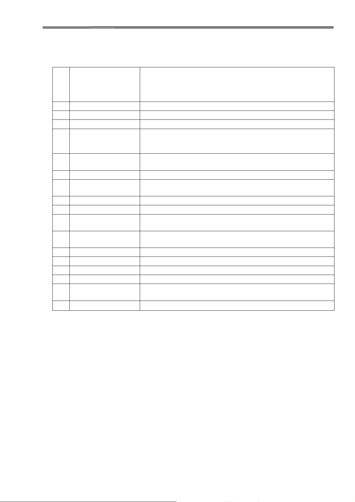
At slanted position, it stacks cut sheets; at flat position, it
separates fanfold printouts from incoming forms.
7
Top Covers 1&2
Protect the internal parts and reduce the noise.
8
Head Gap Lever
Adjusts the gap between the print head and various
form thickness.
9
Paper Path Lever
Selects various paper sources.
10
Upper Friction
Guides the form when cut sheets or fanfold forms are used.
11
Power Socket
A power cord is plugged into the socket to supply the
power.
12
Interfaces
The interface cable of the host computer is plugged into
one of the interfaces.
13
Mute Cover Latch
You must open it before you open the top cover 1.
14
Print Head
Utilizes 24 needles to strike on ink ribbon and paper.
15
Ribbon Cartridge
Holds the ink ribbon fabric.
16
Tractors
Holds and transports fanfold forms.
17
Paper Guides
Left/Right
Sliding the guides varies the form width and the left
margin on a cut sheet.
18
Cut Sheet Support
A flat surface supports a sheet or multi-part form.
1.4 Parts description
4
Page 18
Tally Dascom 2610
2 Installation
2.1 Placing the printer
Place the printer on a solid, flat, stable surface such that the printer sits firmly and cannot
move. Select an environment with sufficient ventilation, easy access to the control panel and
paper input areas as well as the printed output.
When selecting the printer location, observe the following additional requirements:
1) Never place the printer near to any flammable gas or explosive
substances.
2) Do not expose the printer to direct sunlight. If you cannot avoid
placing the printer near a window, protect it from the sunlight with a
curtain.
3) When connecting a computer to the printer, make sure the maximum
recommended cable length is not exceeded.
4) Ensure sufficient distance between the printer and any heating
devices/radiators.
5) Avoid exposing the printer to extreme temperature or air humidity
fluctuations. Above all, avoid dusty environments.
2.2 Connecting the printer
This printer is configured with a Parallel, USB and Ethernet interface as standard. An optional
Serial interface can be installed additionally.
5
Page 19

Tally Dascom 2610
2.2.1 Parallel interface (IEEE 1284)
Make sure that the printer and the computer are switched off and connect the parallel cable
between the printer and the computer. Lock the connector with the 2 clips on the printer
interface connector; tighten up the 2 screws on the other end connecting to the computer.
2.2.2 USB 2.0 (Full Speed)
Plug in the USB cable to the printer and the computer.
2.2.3 Ethernet
6
Page 20

Tally Dascom 2610
2.2.4 Serial Interface (RS-232C) as option
2.2.5 Connecting the power
Plug in the power cord to the printer power socket as shown in the diagram.
Connect the printer to the correct voltage power source.
The socket-outlet shall be installed near the equipment and shall
be easily accessible.
2.2.6 Switch on the printer
Switch on the printer as shown in the diagram.
7
Page 21

Tally Dascom 2610
2.3 Installing the ribbon cartridge
1) Switch off the power.
2) Unfold the top cover and follow the steps 1.2.3.4 in the below picture.
3) Flip the upper friction assembly
8
Page 22

Tally Dascom 2610
4) Insert the ribbon cartridge till it is tightly locked in position.
5) Insert the ribbon fabric in between the print head and ribbon mask.
6) Turn the knob on the left hand side several times in order to tighten the fabric, and the
fabric will slide downwards into the correct position between printhead and ribbon mask
after the moving.
7) Restore the upper friction assembly to its original position.
Print head may be hot, please move the printhead by moving the carriage.
9
Page 23
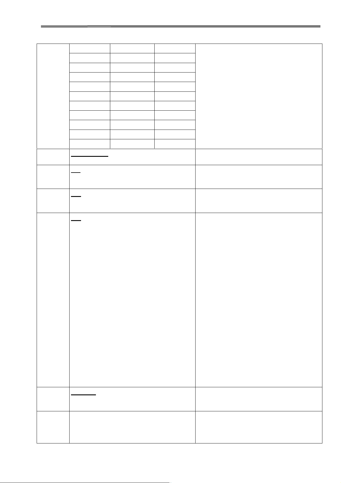
Tally Dascom 2610
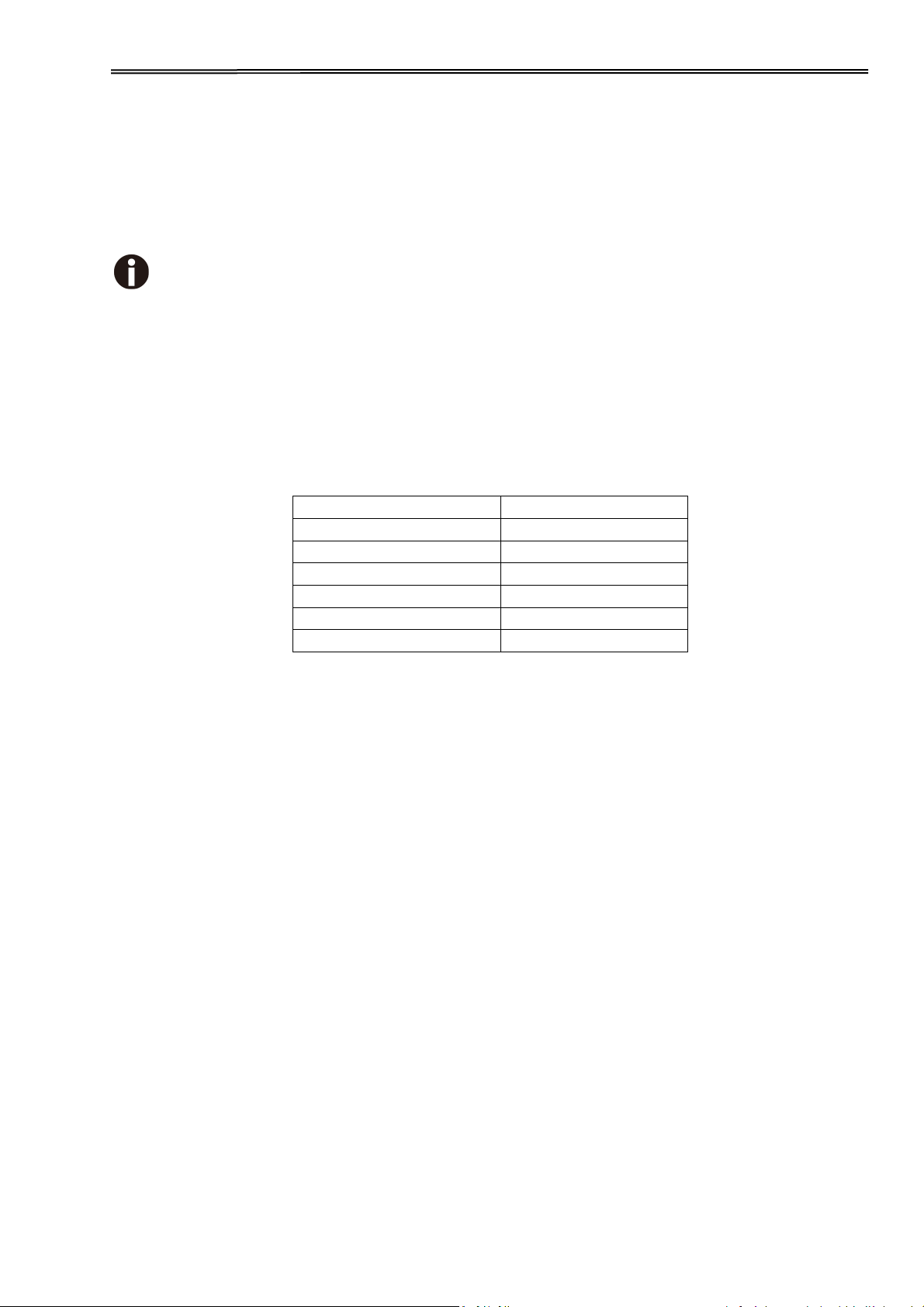
Paper type
Lever position
1-part
1
Original + 1 copy
2
Original + 2 copies
3
Original + 3 copies
4
Original + 4 copies
5
Original + 5 copies
6
3 Installing the paper
The printer can handle either single sheets or continuous forms. The printer is able to print up
to 5 copies (original plus 5).
To ensure the print quality and protect the print head, set a proper print gap by the
gap lever (see 3.1) for the form thickness and do not load folded, damaged,
wrinkled, or curled paper.
3.1 Adjusting the print gap for various form thicknesses
The print gap lever is on the left side of the printer inside the top cover.
Take care to adjust the print gap lever to a suitable position whenever you change the number
of copies being printed. Using the wrong print gap may cause print head damage or paper
jams.
The recommended gap lever position for different form thickness is:
The position “Ribbon” only is suitable for loading the ribbon. When the lever is set higher than
appropriate it will result in poor print. The ribbon and head life will be shortened.
10
Page 24

Tally Dascom 2610
3.2 Paper path introduction
3.2.1 Cut sheet paper handling (front friction only)
1) Place the paper path lever to the cut sheet position.
2) Unlock the front cover with the latch to unfold the cut sheet support.
3) Adjust the gap lever if necessary; see 3.1.
4) It is recommended to align the left paper guide exactly to the mark > I <. This marks the left
edge of the stationery. Slide the right guide to the position of the right edge of the stationery.
5) Insert the stationery straightly all the way into the guided slot until it stops.
6) Press the load key to feed the paper to the correct print position, automatically. The
printer clears the Paper End condition and goes into the ready or online state.
11
Page 25
Tally Dascom 2610
3.2.2 Fanfold paper handling
3.2.2.1 Front push tractors for fanfold
1) Close the front cover if previously opened. Switch the paper path lever to one of the
desired tractor positions.
2) Move the paper path lever to the desired position.
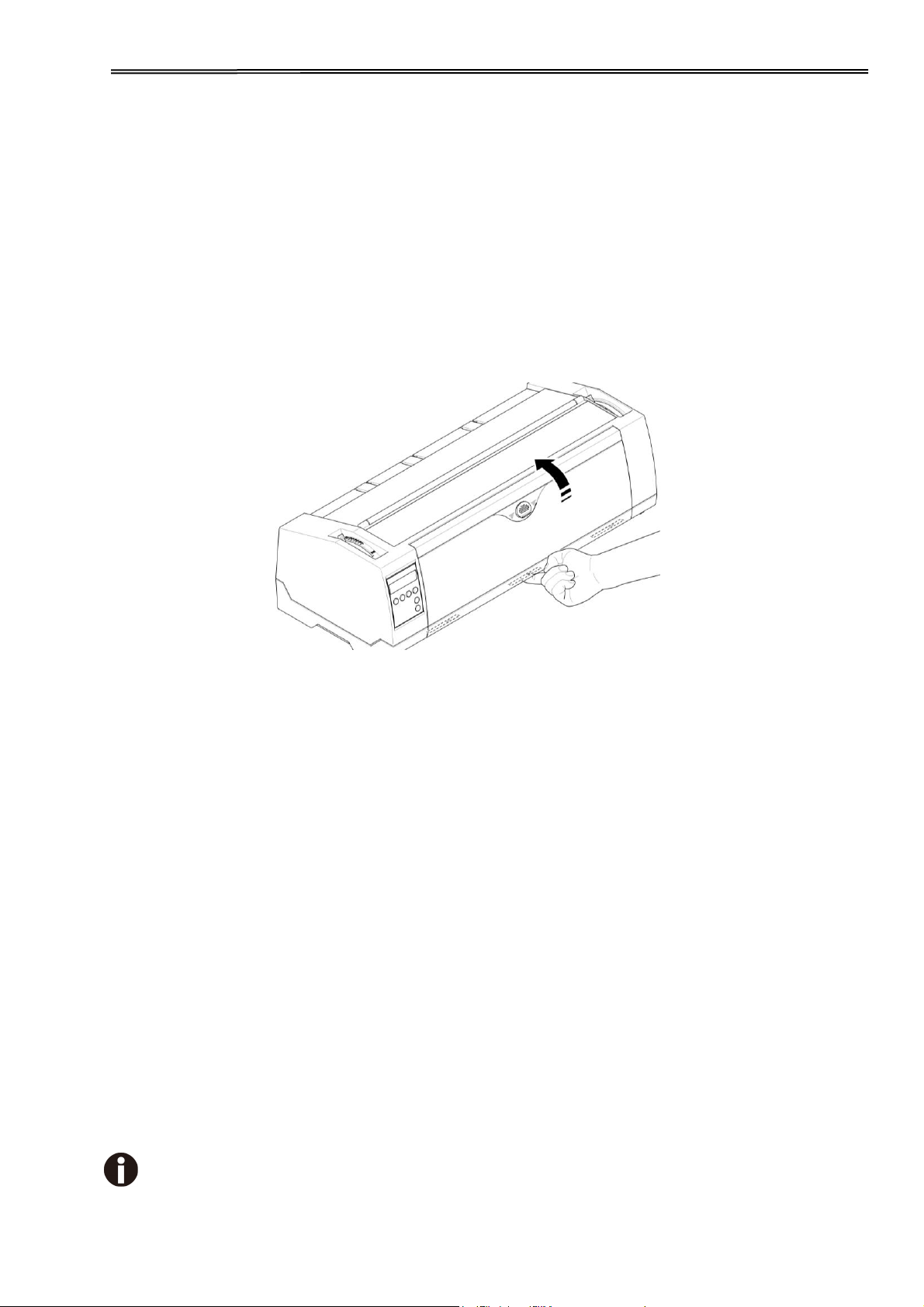
3) Adjust the head gap lever if necessary.
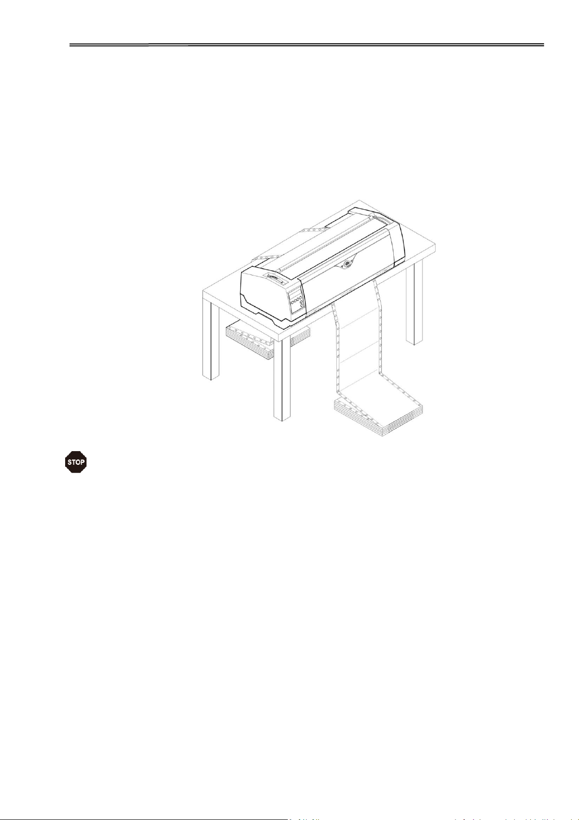
4) Open the front cover by tilting the cover from bottom to the top, and make sure it’s locked in
place (see below pictures).
Lock the front cover in the way that is shown in the pictures.
Make sure the front cover is locked.
12
Page 26

Tally Dascom 2610
5) If you do not need to adjust the left margin go to the next step. Open the right and left
tractor flaps, insert fanfold paper into the left-hand tractor, and make sure that at least
three paper transport holes are positioned on the tractor pins, close the tractor flap,
open the latch lever and align the tractor so that the first printing position on the
paper matches the IIIIXIIII mark on the printer housing, then lock the lever again.
6) Align the right-hand tractor to the width of the paper and insert the paper (Make sure that it
is inserted by the same length as on the left-hand tractor in order to avoid any paper jam).
Then close the tractor flap and slide the tractor to the right until the paper is slightly
tensioned, then lock the tractor.
7) Lower the front cover, switch the printer on.
For LCD: The active paper source (TrFront) appears in the display, the paper will
automatically load when the printer is in online mode and receives data from the
computer. Also, you can press the load key (key 4) only to load paper before
starting the printout.
For LED: The paper will automatically load when the printer is in online mode and
receives data from the computer. Also, you can press the load key (key 2) only to
load paper before starting the printout.
13
Page 27

Tally Dascom 2610
3.2.2.2 Rear tractors for fanfold
14
Page 28

Tally Dascom 2610
3.2.2.3 Top pull tractors for fanfold
For the steps ② and ③, please refer to the 2.3
15
Page 29

Tally Dascom 2610
3.2.3 Top-Of-Form adjustment
For pull tractor (PullTr), follow the steps below to adjust the first print position:
1) Remove Paper from printer.
2) Power on the printer.
3) Lift the Top Cover so you can see the transparent ribbon guide in front of the
print head.
4) Install the paper into the pull tractor.
5) Move the paper with the hand wheel so the perforation of the fanfold paper
lies exactly at the top of the transparent ribbon guide.
6) Close the Top Cover.
7) Press the Load key on the panel.
8) The printer now moves the paper to the correct first print position on a page (TOF).
16
Page 30

Tally Dascom 2610
4 Control Panel Operation
General functions for the keys are clearly designated on the Panel label. Some other special settings
need pressing multiple switches simultaneously or holding some keys when powering on the printer.
This Chapter will describe the functions of the keys and display (LEDs or LCD) on the Panel.
4.1 Operation of the LED Panel
4.1.1 Keys and Indicators
On the Panel, there are four keys, each with its name from left to right:【Online】,【Load/Eject】,
【Speed】and【Tear】. The names of five indicators from left to right are:【Online】,【Tractor】,
【Speed】,【Paper Out】and【Power/Error】above.
Please refer to the below diagram for the Panel layout:
Below describes the function of each key/indicator:
◆ Indicators
1)【Online】lights up to indicate online and turns off to indicate off-line.
2)【Tractor】lights up to indicate utilizing tractors and turns off to indicate front friction state.
3)【Speed】Speed lights up to indicate higher print speed or is off if printing in higher quality based on
selected Font.
4)【Paper Out】lights up to indicate out-of-paper warning and turns off to indicate paper loaded.
5)【Power/Error】normally lights up to indicate power on state. Please refer to 5.
Error Indications on LED for the description on flashing of this indicator.
17
Page 31

Tally Dascom 2610
◆ Keys
1)【Online】
a) Every press on this switch toggles the status between Online and Offline. When the printer is
Online, it receives data from the host; while it is Offline, it stops the printing and signals the host to
stop sending data.
b) Press the key【Online】for the below operations:
Before and after special setup: Most of the special setup requires Offline operation. A
press on【Online】key brings the printer Offline to carry out the special setup; after that,
pressing【Online】brings the printer back online.
Halt the printing for error recovery: Pressing【Online】brings the printer Offline for error
recoveries like paper jam and so on. After the recovery, press【Online】to continue the
printing.
2)【Load/Eject】
If paper is already loaded:
Single sheet - - > The printer ejects the paper;
Tractor front and rear - - > The printer moves the paper in to Park position.
If paper is not loaded:
Transport the paper to the first print position (TOF).
3)【Speed】
Toggles between high speed and high quality print depending on menu settings.
4)【Tear】
When fanfold stationery are installed in an active tractor path, a press of this key advances the
perforation of the stationery to the cutting edge of the tear-bar. This key is invalid for cut sheets
and Top Pull Tractor.
18
Page 32

Tally Dascom 2610
Function
Name
Switch
Operation
Function Description
Offline
{S1}
LED light ON: Online; LED light OFF: Offline;
Load/Eject
{S2}
Load: Load the paper from active paper path to first print
position.
Eject: Either park the fanfold paper or eject cut sheet
paper.
Tear Off
{S4}
This is valid for tractor mode only. It feeds the form to the
tear-off position. After tearing off the form, printing starts on the
next TOF (top of form) by:
pressing S4 once, or
receiving print data from the host.
4.1.2 Online Operations
19
Page 33

Tally Dascom 2610
Function
Name
Switch
Operation
Function Description.
Online
{S1}
LED light ON: Online; LED light OFF: Offline.
Load/Eject
{S2}
Load: Load the paper from active paper path to first print
position.
Eject: Either park the fanfold paper or eject cut sheet paper.
Speed
{S3}
Toggle Between HS-Draft /Draft or NLQ/LQ.
LF/FF
{S4}
Brief press: Linefeed, Longer hold: Formfeed.
Setup Menu
[S2] +[S3]
Enter Printer Setup Menu.
Clear Buffer
and Reset
[S1] +[S2]
Clears the print buffer.
Initializes the printer to power on configuration.
4.1.3 Offline Operations
20
Page 34

Tally Dascom 2610
Detailed descriptions of the above functions:
◆ Speed
If LQ font is currently set in the configuration, lighting up of the【Speed】LED forces NLQ font
printouts; turning off【Speed】indicates LQ printouts.
If Draft is currently set in the configuration, lighting up of the【Speed】LED forces HS Draft printouts;
turning off【Speed】indicates Draft printouts.
◆ Setup Menu
See Chapter 5 for details.
◆ Clear Buffer and Reset
The printer has high capacity storage (buffer) to store the data from the host computer. Sometimes it is
required to halt the printing to clear a fault. Resuming the printing at this point may cause erratic
printouts because some of the un-processed data in the buffer may be truncated. Therefore, it is
recommended clearing the buffer after the recovery with following procedures: (Turning off the printer
is an alternative)
1) Terminate the print job in the host.
2) Press the【Online】key to bring the printer off-line. The printing will stop, but un-processed data still
resides in the buffer.
3) Hold【Online】and 【Load/Eject】keys simultaneously. The buffer will be cleared and the printer will
automatically warm boot.
4) Probably you need to repeat step 2-3 times as the print job in the host spooler may be very large.
21
Page 35

Tally Dascom 2610
Function Name
Switch Operation
Function Description
Technical Setup
[S1]
Start Technical Setup / Advanced Menu
(This also includes Self Test Mode).
Menu Unlock
[S2]+[S3]
Override Menu Lock Function if Menu is
locked.
Status Page
[S4]
Print Status Page.
Load Defaults
[S1]+[S2]+ [S3]+[S4]
Load Default Settings.
4.1.4 Power-On Operations
Detail descriptions of the above functions:
◆ Technical Setup
See Chapter 5 for details.
◆ Menu Unlock
Pressing【Load/Eject】and【Speed】keys simultaneously overrides. Menu unlock function if menu is
locked.
◆ Status Page
Print the setup of the printer (Menu).
◆ Load Defaults
Print the setup of the menu and the parameters.
22
Page 36

Tally Dascom 2610
4.2 Operation of the LCD Panel
◆ The Online mode is the printer’s normal operating mode. Data from your computer can be
received and printed.
◆ In the Offline mode the link between printer and computer is interrupted, i.e. no data can
be received and printed.
◆ In the Setup mode you can either select the printer menu or carry out the quick-switch
function. The quick-switch option was included so that you can change the most important
parameters (for example adjustments, character density, font, paper path, adjustments
directly without having to enter them via the menu. The settings for the parameters character
density and font are lost when the printer is switched off. They can be selected permanently in
the menu mode of the printer.
◆ In the Menu mode further printer settings (line spacing, size of the interface buffer etc.) can
be altered and saved permanently.
4.2.1 The LC display
The LC display tells you all the important printer settings and informs you which functions are
currently assigned to which keys.
The upper line informs you that the printer is either in online or offline mode (in the example
below the printer is in the Online mode), and the selected paper path (below: TrFront = tractor
front mode).
23
Page 37

Tally Dascom 2610
4.2.2 Online mode
After switching on, the printer is automatically set to online mode.
Only in this mode can it receive data from the computer.
■
Online key: Toggle between Online and Offline mode.
Tear key (4): Activates the tear function when fanfold paper
■
is loaded.
If Load is displayed above this key, no paper is loaded
in the printer or the paper is in park position. In this case the
display switches between Online and Park Position. Press
the key to feed paper to the printing position.
■
Setup key: Sets the printer to setup mode.
4.2.3 Offline mode
Only in this mode is it possible to perform step, line, or form feeds from the control panel,
however, data cannot be received.
■ Park key (1)
If fanfold paper is loaded in the printer, it is fed to the
park position or the tear position. If a single sheet is
loaded, it is ejected.
■ key (2)
Each press: Paper is transported upwards step by step.
Holding: Continuous transport upwards.
■ key (3)
Each press: Paper is transported downwards step by step.
Holding: Continuous transport downwards.
■ LF/FF (4)
Paper in the printer:
Each press: performs a line feed (LF).
Holding: performs a form feed (FF).
■ Load key (4)
No paper in the printer: The press on this key loads the
paper to the first print position.
■ Setup key: Sets the printer to setup mode.
■ Online key: Sets the printer to online mode.
24
Page 38

Tally Dascom 2610
4.2.4 Setup mode
In this mode, the following settings are available:
■ Setup key: Sets the printer to setup mode, in which the
following settings can be selected.
■ Menu key (1): Other menu settings. Access may be
disabled by menu settings (see note below).
■ Adjust key (2): Sets the Tear position and first printing line
(TOF). If you have the PullTr (Pull - Tractor) selected Adjust
is not available.
■ Char key (4): Sets the font and the number of characters per
inch temporarily.
Access to the other menu settings (Menu) may be disabled by the manufacturer.
Proceed as follows to release this lock temporarily.
1) Switch off the printer for approx. 5 seconds.
2) Switch the printer on again keeping the Setup key pressed.
4.2.5 Power on functions
If you keep one of the following keys pressed during power-on until the printer has completed
initialization, the corresponding function is activated:
◆ If you keep the Online key depressed while turning on the printer, you enter the printer’s
advanced menu mode. The advanced menu mode is described in the section 5.4.2 of this
manual.
◆ If you keep the Setup key depressed while turning on the printer, you regain access to the
printer menu if you had locked it before with the help of the Menu Lock function.
◆ If all four function keys (keys 1 to 4) are depressed simultaneously while turning on the
power, all printer settings are reset to the default values, except the Forml (Form length)
setting in advanced menu mode.
◆ Holding Function key 4 while turning on the printer prints out the parameter settings.
25
Page 39

Tally Dascom 2610
5 Setting parameters for the printer
(Programming via the control panel)
Apart from being able to control your printer via the applications software you use, you can
also program the printer directly. There are two programming options you can use:
◆ Programming via the control panel.
◆ Programming via the interface using Escape sequences or control codes.
Settings made by escape sequences have priority over settings made in menu
mode; therefore they will override these.
Programming via the interface gives you far greater freedom for designing your printed pages,
however, it is also a more sophisticated method and requires some experience with
programming languages and printer control systems.
All programming via the interface is lost after you turn off the printer, whereas the
programming carried out using the control panel is saved and stored even after you turn off
the printer.
5.1 Setting the parameters through the LED Panel
This chapter describes the handing of the operator’s panel without optional display.
Firstly bring the printer Offline. Pressing【Load/Eject】and【Speed】keys simultaneously
activates the parameters setting operation.
5.1.1 Fine tuning the TOF and Tear positions
Below describes how to set TOF demonstrating the general procedures of parameters
configuration via an LED panel (This procedure is valid for front (TrFront) and rear tractor
(TrRear) only):
1) First load fanfold paper in one of the tractors and bring the printer Offline. Pressing
【Load/Eject】and【Speed】keys simultaneously activates the parameters setting
operation. The printer prints out 2 lines of key assignments valid for the parameter setting
operation.
Key 1 Key 2 Key 3 Key 4
Menu Adjust Char
2) Press【Load/Eject】(i.e. Key 2 in the listed assignment) to enter the operation. The
printer then lists the below line.
TOF Tear
3) “TOF”sets the first printing position from the top edge of the page. “Tear” sets the
desired perforation position. Press【Speed】(i.e. Key 3) to activate the TOF setting. The
printer responds with the below line.
FormAdj 12/72” * Set < > Exit
4) The printer feeds the form to a position where the bottom edge of the first printing line
(TOF) is aligned with the tear edge of the printer. Press【Load/Eject】or【Speed】to
26
Page 40

Tally Dascom 2610
increment or decrement the TOF value. After adjustment, press Key 1 (Set) to save the
change.
Set the Tear position in the same way. Move the perforation of the stationery
exacly to the Tear Edge.
5.1.2 Select a font
Below example demonstrates how to select Roman LQ font type under the Char setting.
1) First, load fanfold paper to one of the tractors and bring the printer Offline. Pressing
【Load/Eject】and【Speed】keys simultaneously activates the parameters setting
operation. The printer prints out 2 lines of key assignments valid for the parameter
setting operation.
Key 1 Key 2 Key 3 Key 4
Menu Adjust Char
2) Press【Tear】(i.e. Key 4 in the listed assignment) to enter the Character setting. The
printer then lists the below line:
Font CPI
3) “Font” allows selecting desired font type and “CPI” allows setting desired character pitch.
Press【Load/Eject】(i.e. Key 2) to enter the Font submenu. The printer responds with the
below line:
HS-Draft * Set < > Exit
4) HS-Draft * indicates the current selection. Set means to save the change. < selects the
previous item. > selects the next item. Exit exits the menu. Here, press【Speed】(i.e. Key
3) to show the next font. Keep pressing【Speed】until the print shows Roman:
Roman LQ Set < > Exit
5) Press【Online】to save the change of font type to Roman. The printer sounds the
buzzer and prints the below line to confirm successful change.
Roman LQ * Set < > Exit
Modify the CPI in a similar way if desired (these two are only temporarily stored).
27
Page 41

Tally Dascom 2610
5.1.3 Settings within Menu
Below example demonstrates how to select an Emulation within the Menu.
1) First load fanfold paper to one of the tractor and bring the printer Offline. Pressing
【Load/Eject】and【Speed】keys simultaneously activates the parameters setting
operation. The printer prints out 2 lines of key assignments valid for the parameter setting
operation.
Key 1 Key 2 Key 3 Key 4
Menu Adjust Char
2) Press【Online】(i.e. Key 1) to get into Menu operation. The printer prints:
Back Print Menu Next
3) Press【Tear】(i.e. Key 4) repeatedly till “Emulation” appears on the printout:
Back ESCChar Emulation Next
4) Press【Speed】(i.e. Key 3) to get into emulation configuration. The printer prints:
Epson LQ-2550 * Set < > Exit
5) Epson LQ-2550 * indicates the current emulation is LQ-2550. Set means to save the
change. < selects the previous item. > selects the next item. Exit leaves the menu. Press
【Speed】(i.e. Key 3) to show the next emulation:
Epson LQ-2170 Set < > Exit
6) Press 【Online】 (i.e. Key 1) to save the selection of Epson LQ-2170 emulation. The printer
sounds the buzzer and prints the below line to confirm successful change.
Epson LQ-2170 * Set < > Exit
See 5.4.1 for a full list of valid settings.
28
Page 42

Tally Dascom 2610
5.2 Setting the parameters through the LCD Panel
This chapter describes the handling of the operator’s panel with optional display.
5.2.1 Enabling access to menu mode
The menu can be locked by default to protect it from accidental or unauthorized access.
Proceed as follows to release this lock temporarily.
1) Switch off the printer for approx. 5 seconds.
2) Switch the printer on again keeping the Setup key pressed.
Calling up the menu
You can access the menu in the following way:
Press the Setup key. The printer switches to Setup
mode. (The Setup mode can be selected both in the
Online and Offline mode)
To access the printer menu, press the key directly
underneath the word Menu (1).
29
Page 43

Tally Dascom 2610
5.2.2 Menu configurations
Every printer is shipped with factory default settings. Basic settings such as emulation,
character size, form length etc., which many applications make use of, are set. At the end of
this chapter you will find a menu printout which shows you the printer’s default settings.
Your printer allows you to set and use five independent menu configurations. If one of your
applications, for example, requires an IBM printer while another program works better with an
EPSON printer, you can set an IBM emulation configuration with the desired settings, and set
the second configuration as an EPSON emulation.
The active menu is always the one you used last. When you switch on the printer for the very
first time, menu no. 1 is loaded. Menu no.1 only remains active until you load another menu.
The last active menu is stored even after the printer is switched off and is reloaded
automatically when the printer is switched on again.
For example, to change from menu no. 1 to menu no. 3:
Press Setup key.
Press Menu (1) key.
Press Menu (3) key.
Now the following message appears in the LC display:
Now press the < (2) or > (3) key repeatedly until Load Menu=3
appears.
Then select menu no. 3 as the current setting using the Set key
(1). The currently active setting is marked with an asterisk (*).
If changing menus it is possible that the printer initializes due to different
emulation settings.
30
Page 44

Tally Dascom 2610
Menu Printout
31
Page 45

Tally Dascom 2610
5.2.3 Menu handling
You can navigate in the current menu using the four function and selection keys arranged
below the LC display field. Each function and parameter displayed in the LCD is executed or
selected by the corresponding key below, respectively. Usually two parameter groups are
combined at one level. In the following example, these are the LPI and Skip parameter
groups.
If you do not wish to change one of the two parameters you can either press the Next key (to
access the two following parameter groups in the menu), or you can press the Back key (to
access the two previous parameter groups in the menu).
If you want to change a setting, (e.g. the line density), then press the LPI key (LPI = lines per
inch) to access the actual parameter level.
The currently valid setting is marked by an asterisk (in the example below the current
setting is 6 lpi). With the < and > keys you can view the other parameters available for
this setting.
Example:
Save settings
Once the desired parameter is displayed on the LC display, you can save it by pressing the Set
key. The parameter is then set and the printer automatically displays the parameter groups
again. With the Exit key you can leave the sublevel without saving your changes.
32
Page 46

Tally Dascom 2610
5.2.4 Selecting the LC display language
This section describes how to make settings in the menu, using the selection of the national
language as an example.
In this user guide all LC display messages are shown in English language. Your printer offers
also the possibility to show the display messages in German, French, Italian, Spanish or
Turkish language. This example shows how to change from the English language to the
German language. The same procedure applies to the other languages (French, Italian,
Spanish and Turkish).
Select the Setup mode by pressing the Setup key.
Setup mode and Menu mode may be disabled. Hold
down the Setup key while switching on the printer to
enable menu mode. If you want to enable access to this
mode permanently, you need to change the appropriate
setting in the menu.
Press the next key (4) several times until the display indicates
Language.
Press the Language key (3).
The display now changes to Parameter mode and indicates
English in the top line.
The lower line displays Set and Exit. The two arrows < (2)
and > (3) represent the symbols for parameter selection
(“<” indicates descending and “>” ascending). Press the <
(2) or > (3) key until the desired language is displayed, in
our example German.
Save your selection by pressing the Set key (1). An acoustic
signal verifies this action.
You can exit Parameter mode without saving a setting by
pressing the Exit key (4), the old setting is retained.
After saving your setting (Set), the display in our example
Ges.Men indicates the following text:
This setting is retained even after switching off
your printer.
Terminating Setup mode press either
the Setup key to change into Offline mode or the
Online key to change to Online mode.
33
Page 47

Tally Dascom 2610
MENU
Back→
←Next
Print
Menu
Reset
Font
CPI
LPI
Skip
ESCChar
Emulate
Bidir
I/O
Serial
1)
Interf.
Buffer
ETH-INT
Baud
1)
Format
1)
Special
1) 2)
Protocol
1)
DTR
1)
CG-Tab
CharSet
Paper
Single
Tr Front
Tr Rear
Pull Tr
Auto Tear
Barcode
Barmode
FFmode
LeftMrg
RightMrg
Country
Sl.Zero
Auto-CR
Auto-LF
MenLock
Language
Width
Eject
Quietm
5.3 Menu structure
The menu structure of your printer may be slightly different from the example shown here,
depending on the printer software.
1) Only with optional serial interface
2) Only if ENQ/STX, ETX/ACK or ACK/NAK protocol is selected
34
Page 48

Tally Dascom 2610
Menu
Valid Settings
Function
Adjust
TOF Tear
Setting the tear position.
Setting the first printing line (TOF).
Print
Print the menu settings.
Menu
Load Menu=1
Load Menu=2 Load Menu=3
Load Menu=4 Load Menu=5
A menu is loaded, you can choose
between five menus.
Reset
Reset Menu Yes No
Press the No (1) or Yes (2) key to select
the desired setting.
All manually altered settings in the current
menu are lost when it is reset to the
default settings.
We therefore recommend that you print
out the menu first.
Quietm
Off
On
Switches between normal and quiet mode
printing. For all printing
modes, the print-out is made with the
bidirectional method in quiet mode
printing. In the first step the first row of
pins is activated, during the second step
the second row is used.
Font
HS-Draft
Draft
Roman NLQ
This parameter selects the character style
and its quality permanently.
Roman LQ
Roman PS NLQ
Roman PS LQ
CourierNLQ
Sans Serif NLQ
Sans Serif LQ
Courier LQ
S Serif PS NLQ
S Serif PS LQ
5.4 Full list parameters setting
In order to meet individual requirements of printer functionality, users may modify the
printer configuration settings accordingly as follows: start by pressing [Load/Eject] +
[Speed] in offline mode. The printer will enter Main Menu settings setup mode. Follow the
instructions printed on how to do the required setting changes. When a new setting is
saved, it becomes effective, even when printer is power cycled.
5.4.1 Menu Configuration list
35
Page 49

Tally Dascom 2610
Prestige NLQ
Prestige LQ
Script NLQ
Script LQ
OCR-B NLQ
OCR-B LQ
OCR-A NLQ
OCR-A LQ
Orator NLQ
Courier I NLQ
Courier I LQ
Orator LQ
Souvenir NLQ
Courier I PS NLQ
Gothic NLQ
Souvenir LQ
Courier I PS LQ
Gothic LQ
CPI
10 CPI, 12 CPI, 15 CPI, 17.1 CPI, 20
CPI, 5 CPI, 6 CPI, 7.5 CPI, 8.6 CPI.
Sets the characters per inch (character
pitch). The higher parameter the smaller
character spacing.
LPI
6 LPI, 8 LPI, 12 LPI, 2 LPI, 3 LPI, 4 LPI.
Sets the lines per inch (line density). The
higher parameter the smaller line spacing
(random LPI can be selected via the ESC
sequences).
Skip
Skip=0.0 Inch,
Skip=0.5 Inch, Skip=1.0 Inch,
Skip=1.5 Inch, Skip=2.0 Inch,
Skip=2.5 Inch, Skip=3.0 Inch,
Skip=3.5 Inch.
Skips the perforation; 7 different values
(in inches) can be defined.
ESCChar
ESC ESC+$$
Selects the start signal for control
sequences. Setting ESC: Only character
Escape can be used. Setting ESC+$$:
Character Escape or alternatively two
$ characters ($$) can be used.
Emulate
Epson LQ-2550
Epson LQ-2170
IBM Propr. XL24 Epson FX
IBM ProXL24+AGM MTPL
Selects the emulation. When a printer
understands the control set written for
another printer type, it is said to emulate
the other printer.
Bidir
Bidir=On Bidir=Off
Setting On: Printer prints in both
directions (bidirectional).
Setting Off: Printer prints only in one
direction (from left to right).
I/O
Serial
Baud
Baud=9600
Baud=19200
Baud=600
Baud=1200
Baud=2400
Baud=4800
Selects the data transmission rate (baud
rate) (baud=bit per second).
36
Page 50

Tally Dascom 2610
Format
8Bit No 1Stop
8Bit No 2Stop
8Bit Even 1Stop
8Bit Odd 1Stop
8Bit Mark 1Stop
8Bit Spc 1Stop
7Bit No 2Stop
7Bit Even 1Stop
7Bit Odd 1Stop
7Bit Odd 2Stop
7Bit Mark 1Stop
7Bit Spc 1Stop
7Bit Mark 2Stop
7Bit Spc 2Stop
This parameter serves to define the
number of data bits, the parity check for
received data bytes and the number of
stop bits per data byte.
Protocol
XON/XOFF
Robust-
XON/XOFF
ENQ/STX
ETX/ACK
ACK/NAK
This parameter serves to select the type
of protocol, i.e. a certain set of rules and
procedures for ensuring error-free data
exchanges between computer and
printer.
DTR
DTR=DTR
DTR=Ready
Defines the conductor to which the DTR
signal is connected
(DTR=Data Terminal Ready).
Interf.
Interf.=Share
Interf.=Parallel
Interf.=Serial
Selects the interface. Printer is
configured either for parallel. Ethernet or
optional serial connection or in automatic
change for the parallel or the optional
serial interface (Shared).
Buffer
Buffer=0 KB
Buffer=32 KB
Buffer=64 KB
Buffer=96 KB
Buffer=128 KB
Buffer=160KB
Buffer=192KB
Buffer=224KB
Buffer=256KB
Selects the size of the interface buffer.
37
Page 51

Tally Dascom 2610
ETH-INT
IP-Addr
Octets 1-4
0 to 255
Input of the IP address of the printer
This menu level offers the possibility to
set the IP address, which is divided into
four digit groups (octet 1 to 4).
Gateway
Octets 1-4
0 to 255
Input of the Gateway address of the
printer.
Subnet
Octets 1-4
0 to 255
Input of the Subnet mask address of the
printer.
IP Get M
DHCP BOOTP
Static
Selects the way of administrating the IP
address.
Banner
Off On
Specifies whether a banner page is to be
printed out, when using the LPD/LPR
protocol.
EthSpeed
Auto-Sense
The transmission speed is detected
automatically.
10Mbit Half
Sets the transmission speed to 10 MBit
half duplex per second.
10Mbit Full
Sets the transmission speed to 10 MBit
full duplex per second.
100Mbit Half
Sets the transmission speed to 100 MBit
half duplex per second.
100Mbit Full
Sets the transmission speed to 100 MBit
full duplex per second.
CG-Tab
Graphic DLL Italic
Only available for Epson
LQ-2550/LQ-2170 emulation. Either the
Epson character set Italics or the IBM
graphics character set or a DLL
(download) character set, as defined
before, can be activated in the code
range from hex. A0 to hex. FE.
CharSet
Extended Standard
Selects the IBM standard characters or
the extended IBM characters.
Country
E-USASCII
E-France
E-German
Selects the national character set. These
character sets can be used according to
the selected emulation.
E-UK
E-Denmark I
E-Sweden
E-Italy
E-Spain I
E-Japan
E-Norway
E-Denmark II
E-Spain II
E-L.America
E-Korea
E-Legal
ISO8859-1
ISO8859-1 SAP
ISO8859-2
ISO8859-5
ISO8859-7
ISO8859-9
ISO8859-15
ELOT-928
BRASCII
Abicomp
Roman8
US-ASCII
French
German
Italian
Swedish
Norwegian
Spanish
Portuguese
Greek DEC
Cro-ASCII
38
Page 52
Tally Dascom 2610
Coax/Twinax
Table 437
New-437
Table 737
775 Baltic
Table 850
New-Dig 850
Table 851
Table 852
Table 857
Table 858
Table 860
Table 861
Old-Code 860
Table 863
Flarro 863
Table 865
865 Hebrew
Table 866
866 Bulgaria
866 Ukraine
866 Kazakhst
Kamenicky
Mazovia
Siemens Turk
DEC Turkish
Table 1250
Table 1251
Table 1252
Table 1253
Table 1254
Table 1257
Sl.Zero
Sl.Zero=Off Sl.Zero=On
Selects if normal zero (0) or the slashed
zero (Ø) is printed.
AutoCR
On Off
Switches the automatic carriage return
on or off after receiving the signal LF (line
feed).
AutoLF
Off On
Switches the automatic line feed (LF) on
or off after receiving the signal CR
(carriage return).
Menlock
Off Menu All
With MenLock=Off, all functions and
settings are accessible without restriction
in Online, Offline and Setup mode.
If MenLock=Menu is activated, all
functions and settings are still accessible
in Online and Offline mode, however, in
Setup mode you can only access the
parameter groups Adjust (setting the print
head gap [Head], top of form [TOF] and
tear position [Tear]), Paperway (setting
the paper path), Font (setting the font)
and the character spacing (CPI), while
access to Menu mode (Menu key) is
disabled.
If you select MenLock=All, you can
access the Online/Offline, Load/Park,
Paper and Paper Feed (LineFeed/Form
Feed, / ) functions in Online and Offline
mode while Setup mode is disabled.
In this case, the Setup menu can only be
called up by holding the key Setup while
switching on the printer.
Language
English German French Italian
Spanish Turkish
The menu can be shown in six
languages.
Paper
Single TrFront TrRear PullTr
Selects the paper parameters Formlen
(form length), FormAdj (first printing
position/TOF) separately for each paper
source in the current menu.
39
Page 53

Tally Dascom 2610
Formlen
Lines
=6 – 132
Default 6LPI = 66
Single:3—22 inches
TrFront、TrRear 、
PullTr:1—22 inches
Sets the form length via line formats.
Please note that the adjustment in Lines
depends on the selected LPI. For
example 8 LPI at a selected line number
of 96 lines results in a form length of 12
inches (96lines/[8lines/inch]) = 12 inches.
The selectable range is between 3 and
21 inches, i.e. for 2 LPI from 6 to 42 lines
and for 12 LPI from 24 to 262 lines.
If the form length is set it will not be
changed by changing the LPI later on.
Standard
No format
DIN A3 (420 mm)
DIN A4 (297 mm)
DIN A5 (210 mm)
DIN B5 (250 mm)
DIN B6 (176 mm)
DIN C6 (162 mm)
Executive 10.5"
Letter 11"
Fanfold 12”
Legal 14"
Selects the form length by standard
formats. Using Standard, different paper
formats can be selected directly, e.g. DIN
A4, Legal, Letter.
The Menu indicates No format if a value
is selected by the Line function or ESC
sequences, which does not correspond
to a standard format.
FormAdj
FormAdj=0 -220/72”
Default 12/72”
Sets the first print position of a form in
n/72 inch, separately adjustable for each
paper path.
Autotear
ViewTear =Off
View=1s/3s/6s
Tear=1s/3s/6s
Tear at TOF
The auto tear function or the auto view
function can be selected as desired.
When auto view is switched on, the last
printed text is visible. As soon as data is
received the paper moves to the “normal”
print position. After printing the printer
waits for the given interval to bring the
paper once more to the auto view
position.
The paper is in the tear off position when
auto tear is switched on, the perforation
of the positioned at the tear off edge of
the printer. If data is received, the paper
returns to the normal print position. After
printing, the printer waits for the given
interval to bring the paper once more to
the tear off position. If the tear off edge
does is not aligned with the perforation of
the paper then this can be corrected.
40
Page 54

Tally Dascom 2610
Width
Width=13.6Inch
Width=8Inch
Width=13.2Inch
Selects the line length in inches. With the
setting of 8 Inch, the printer operates like
a printer with a width of only 8 inches.
Eject
Eject=Top
Eject=Front
This is valid for single sheet mode only. It
controls the exit direction of the friction
sheet paper.
Barcode
Off On
With this function selected it is possible
to print different barcodes and LCP
(Large Character Printing).
Barmode
Unsecured
Secured
Allows printing of normal characters on
the left and right of the barcode.
FFmode
Off On
Specifies whether a form feed is to be
performed when the paper reaches the
top print line.
LeftMrg
Wide: LeftMrg=0 - 134/10”
Narrow: LeftMrg=0 - 78/10”
The left print margin can be set to a fixed
value.
RightMrg
Wide: RightMrg=2 - 136/10”
Narrow: RightMrg=2 - 80/10”
The right print margin can be set to a
fixed value.
41
Page 55

Tally Dascom 2610
Advanced
Menu
Valid Settings
Function
ASCII80
8 inch wide print of test pattern
To check operational readiness, your
printer contains a self-test routine which
allows testing of the printer
configuration, the print quality and
correct operation of your printer.
ASCII136
13.6 inch wide print of test pattern
(only 2610)
H-Dump
With the interface test
(Hex-Dump/H-Dump) you can test data
transmission from the computer to the
printer. During this test, the data from the
computer is printed out in two columns.
The text in the left column is printed in
hexadecimal format and in the right
column in ASCII format.
Hvy Form
HvyForm=ON
HvyForm=OFF
If you set HvyForm=ON, the printer
prints the same line twice at double
strike. This setting ensures that copy
paper produces optimum results.
Formlen
12” 11”
The Formlen function allows you to set
the basic (default) form length to meet
your requirements. 11 inches are usual
in the USA, as opposed to 12 inches in
Europe.
Paphand
PLM
On Off
This item’s full name is Paper Load
Mode. It is located beneath the already
existing menu item “Paphand”(Paper
Handling).
This setting enables(on)/disables(off) a
horizontal carriage movement in order to
flatten the paper so it finds its way into
the upper friction.
However the movement is determined
by the menu items Pagewid & Widthcon.
If Widthcon=Off
2600: The movement of carriage goes
all the way = 8”
2610: The movement of carriage goes
all the way = 13.6”
If Widthcon=On
2600/2610: The movement of carriage
goes rightmost to Pagewid Position.
This function is ON by default and is
valid for Rear Tractor only.
Pagewid
2610: 20—136 /10”
2600: 20—80 /10”
Parameter “Pagewid”. This item’s full
name is Pagewidth.
It is located beneath the already existing
5.4.2 Advanced Menu
42
Page 56

Tally Dascom 2610
menu item “Paphand” (Paper Handling).
This setting tells the printer logic the
width of the installed paper and is valid
for all paper ways.
By default this parameter is maximum
width.
2600: 80 Characters (80/10”)
2610: 136 Characters (136/10”)
The value can be changed in 1/10” in a
range between 20 and 136 (80).
Physlm
Physlm=0 - 30/10”
Permanent (physical) setting of the left
margin. This parameter cannot be
changed by emulation dependent
margin settings. Margin setting values
entered by ESC sequences are added to
the Physlm.
Widthcon
Off On
Parameter “Widthcon”. This item’s full
name is Width Control.
It is located beneath the already existing
menu item “Paphand” (Paper Handling).
This setting enables (on) / disables (off)
the possibility to define the position of
the carriage during loading
& ejecting paper.
If Off
2600: the carriage’s position is 4”
2610: the carriage’s position is 5.3”
If On
2600/2610:Half of Value defined in
Pagewid
This function is OFF by default and is
valid for all paper ways.
CX-bid
CX-bid=ON
CX-bid=OFF
CX-bid=ON sets the parallel interface of
the printer to bidirectional mode (IEEE
1284, Nibble mode), e.g. for Windows
Plug & Play.
CX-bid=OFF sets the interface to
compatibility mode in order to ensure
reliable operation with special external
boxes.
Wrap
Wrap=On
Wrap=Off
Wrap=On: If more characters than can
be printed are transmitted per line, the
characters which cannot be printed on
this line are printed at the beginning of
next line.
Wrap=Off: If more characters than can
be printed are transmitted per line, the
characters which cannot be printed on
this line are cut off.
43
Page 57

Tally Dascom 2610
Sound
Sound=On
Sound=Off
When Sound=On, a beep is generated
every second to notify that paper is
empty.
Pap.back
Pap.back=normal
Pap.back=dark
Pap.back=normal is the standard for
normal paper.
Pap.back=dark can be set to process
paper with a grey back.
Paper with a completely black back side
cannot be used if the ink is
carbon-based. However, the printer can
handle aniline- based black paper
(undefined colors).
APW
APW=Off
APW=On
If APW=On, the printer is in the standard
mode and truncates all data located
beyond the right-hand and left-hand
paper edge. These print data are lost.
When you select APW=Off, the printer
does not prevent undesirable printing on
the platen.
The printer determines the paper width
by means of an optical sensor in the
print head module. The print head
carriage moves once across the
maximum possible printable area of the
paper and stores the width measured in
this process. The measuring process
varies, depending on the paper source
selected.
The measurement is made.
� after power-on and before the first
print job;
� after paper end and before the
subsequent print job;
� after changing the paper source (e.g.
from Tractor 1 to Tractor 2).
When you submit a print job which
exceeds the paper width, the following
message appears in the display:
Paper Width Error – Press Online
The print job is stopped at the measured
paper-end position after printing the first
line.
You can now either cancel the print job
or load suitable paper. In the latter case,
the printer will resume the print job upon
pressing the Online key.
If you press the Online key without
having changed the paper, another
line is printed until reaching the
measured paper-end position.
The sensor interprets dark areas with
44
Page 58

Tally Dascom 2610
a width of 13 mm or more as the
right-hand paper edge.
If the sensor does not detect any
black area, the maximum possible
printing width is used as the printable
area.
SerialN
factory set
With the SerialN function you have the
possibility to change the 12 digit serial
number of the printer. The number can
be written with any ASCII character
between hex 20 and hex 7E.
LED Panel: The Serial Number cannot
be set via menu instead you need to use
the WebPanel.
AssetN
10 digits empty
With the AssetN function you have the
possibility to change the 10 digit asset
number of the printer. The number can
be written with any ASCII character
between hex 20 and hex 7E.
LED Panel: The Asset Number cannot
be set via menu instead you need to use
the WebPanel.
GrSpeed
GrSpeed=Normal
GrSpeed=High
This parameter allows improved Graphic
Speed independently to the driver. It
affects only the print speed of graphic
printouts at 180 x 180 dpi.
Jobcntl
Jobcntl=On
Jobcntl=Off
This parameter activates the printer
language PJL (Printer Job Language) in
connection with the internal Ethernet
interface (ETH-INT) or the external
TallyCom III interface (ETH-EXT).
UltraDr
UltraDr=on
UltraDr=off
Ultra Draft=on, speeds up 17.1 and 20
cpi. Precondition is HS-Draft needs to be
activated.
45
Page 59

Tally Dascom 2610
LED Messages Error/Power ON
Online
Tractor
Speed
Pap.Out
Power/Err.
Hardware Alarm
blink
blink
blink
blink
blink
Switch Paper lever
(intermediate beep)
Off
normal
normal
blink
blink
Paper Width Error
blink
off
blink
blink
blink
EEPROM Error
blink
blink
off
blink
blink
Serial Interface Error
blink
blink
blink
off
blink
“Printhead Hot” Message
blink
off
off
blink
blink
“Check Ribbon” Message
blink
off
off
off
blink
Serial Boot Mode
on
on
off
on
Off
Parallel Boot Mode
on
off
off
on
off
RAM Error
off
on
on
on
off
Missing FPGA
off
on
on
on
on
Monitor Mode for ROM
Debugger
on
on
on
off
off
Wrong Header (temporary)
on
off
off
off
off
Sensor Controller (ST8) Error
off
off
on
on
off
Firmware Download Is
Running
One lit LED is moving around in a circle, the others
are off
5.5 Display messages
If the printer detects an internal fault or user error or if it expects you to do something, a
message will appear in the LC display (LED’s display message reference below table 5.6.1).
It also displays the status during an operation (e.g. Initializing). Below you will find a list of
messages with brief descriptions of each message.
5.5.1 Messages LED Panel
If one of the messages cannot be removed by power cycling the printer call your
service.
46
Page 60
Tally Dascom 2610
LCD Messages Meaning
Eject error
The printer cannot eject the paper/advance it to
park position.
Hardware Alarm
Internal hardware error, contact your dealer or
service technician.
Head hot
The print head is too hot. The printer will reduce
its print speed.
Initializing
This message appears during the printer’s
initializing phase after switching on the printer.
Load error
The printer fails to load the paper.
Loading default
Factory defined parameters will be reloaded in all
available menus after switching on the printer.
Load paper from
The printer has detected paper end during
operation/printer was switched on with no paper
loaded.
Parity error
A parity error during data transmission is
indicated.
Park position
Printer was switched on with no paper loaded.
Press any key
The user is requested to press any key.
Selftest
After power-on, the printer executes a short
hardware self-test.
Tear Paper off
The user is requested to tear off paper which has
been advanced to the tear.
Switch Paper Lever
Choose correct paper path. Turn paper lever
5.5.2 Messages LCD Panel
47
Page 61

Tally Dascom 2610
6 Web Panel and Internal Ethernet Interface
6.1 Summary
6.1.1 Introduction
It is assumed you have the following:
◆ A working knowledge of your network system and related utilities.
◆ Access to the supervisor or administrator account as a network administrator.
6.1.2 Supported Environments
The built-in network interface supports the following platforms and protocols:
◆ Microsoft® Windows® NT 4.0, 2000, XP,7,8, Server 2003/2008/2012
◆ Linux – Red Hat®, SuSE®
◆ Unix® – Sun Solaris®, HP-UX®, IBM AIX®
◆ TCP/IP, HTTP, LPR/LPD
6.1.3 Network Interface and Cabling
The printer requires:
◆ Ethernet 10Base-TX or 100Base-TX interface.
◆ Category 5e or 6 Ethernet cable with RJ-45 socket connectors.
6.1.4 Connecting the Printer
Connect the Ethernet cable to the network interface port RJ-45 connector on the rear center
of the printer.
6.1.5 Network Interface Status
There are two status lights (LEDs) next to the RJ-45 connector on the rear panel.
◆ Right green light (Link Status) is solid: This shows the printer is connected to the network.
◆ Right green light is blinking: Shows network activity.
◆ Left yellow light (Duplex Status) is solid: Shows network interface is in full duplex mode.
Unless the link status light is green, the printer will not be able to connect to the
Network.
48
Page 62

Tally Dascom 2610
6.2 IP Configuration
6.2.1 Network IP Configuration
The network interface of the printer requires an IP address.
There are several ways to assign an IP address to the printer:
◆ DHCP (A Dynamic Host Configuration Protocol server assigned IP address.)
◆ Static (An IP address obtained from your network administrator added to the printer
manually.)
◆ BOOTP (Bootstrap Protocol server assigned IP address.)
6.2.2 Assigning the IP Address
If the printer menu is locked, please see the 4.2.5.
1. Automatic DHCP IP address assignment:
◆ Press <Setup>, then <Menu>.
◆ Press <Next> until the I/O selection appears. Select <I/O>.
◆ Press <Next> until the ETH-INT selection appears. Select <ETH-INT>.
◆ Press <Next> until the IP Get M selection appears. Select <IP Get M> Select <DHCP>.
◆ Verify that your printer was assigned an IP address by printing the “Current Settings”
configuration page or in the operator panel menu.
1) At power-up, the printer network interface broadcasts a DHCP request for an IP address.
If a DHCP server is present, the request will be processed, and an IP address will be
returned to the printer network interface. Upon receipt of the IP address, the printer
accepts and uses this new IP address (and subnet mask, and default gateway, if any).
2) Once an IP address has been assigned, the printer network interface will no longer
broadcast DHCP requests. The printer will broadcast a DHCP request each time you turn
on the printer.
3) The DHCP server may grant a temporary IP address, called a temporary lease or
temporary reservation, which expires later, or may grant a permanent or unlimited time
lease or reservation, which does not expire.
4) Devices such as the printer that are granted a temporary lease will be notified before the
lease expires and asked if they would like to extend the lease. The printer network
interface will continue extending its lease indefinitely (unless prohibited by your DHCP
server configuration), and thus maintain a consistent IP address.
5)
If the printer is not turned on or is not connected to the network when the DHCP server is
sending requests to extend the lease, the lease will not be extended. The DHCP server
will cancel the lease and may assign the IP address to another device. Therefore, it is
highly recommended to explicitly specify the printer lease as permanent or unlimited in
your DHCP server configuration.
49
Page 63

Tally Dascom 2610
2. Static assignment using the operator panel:
◆ Press < Setup >, then < Menu >.
◆ Press < Next > until the I/O selection appears. Select < I/O >.
◆ Press < Next > until the ETH-INT selection appears. Select < ETH-INT >, then< IP Addr >
◆ Enter the value for Octet 1by pressing < OCTET 1 >. Use the forward and backward
arrows to increment/decrement the number. When finished with each entry press
< Set > which will set the currently displayed value. To exit out without changing the value
press < Exit >. Enter the Octet 2 value in the same way, pressing < OCTET 2 >. To get to
Octet 3 and Octet 4, select < Next > and then select <OCTET 3> and < OCTET 4 >.
◆ Enter the default Gateway and Subnet mask in the same way. < Gateway > is available
from the screen you are returned to. Press < Next > to select < Subnet >.
◆ Enter the IP address get method under the selection <IP Get M>. Select <Static>.
3. BOOTP IP address assignment:
◆ Press <Setup>, then <Menu>.
◆ Press <Next> until the I/O selection appears. Select <I/O>.
◆ Press <Next> until the ETH-INT selection appears. Select <ETH-INT>.
◆ Press <Next> until the IP Get M selection appears. Select <IP Get M> Select <BOOTP>
◆ Obtain the Ethernet MAC address by printing the “Current Settings” configuration page,
Turn off printer.
◆ Configure your BOOTP server with desired IP address and MAC address.
◆ Turn on printer.
◆ Verify that the printer network interface received an IP address by printing the “Current
Settings” configuration page or in the operator panel menu.
50
Page 64

Tally Dascom 2610
6.3 WebPanel
6.3.1 Introduction
WebPanel is an intuitive browser interface that allows you to remotely manage your network
attached printer. From WebPanel, you can do virtually everything you can do from the printer's
control panel.
In addition, WebPanel provides full access to all of the TallyCom networking features. Before
using WebPanel, you must configure your printer with an IP address, using one of the three
methods discussed in the Assigning the IP Address section above.
The screenshots that are used in this document to demonstrate the functionality
may vary depending on the printer model.
6.3.2 Web Browser
WebPanel is accessed from the printer through a web browser, i.e.Internet Explorer, Firefox,
etc. The browser needs to be configured with cache and history empty, and the browser set
up to check for new pages every time, to insure that connections to WebPanel will produce
the latest data.
WebPanel does not work through a proxy server. Therefore, the web browser must be setup
to NOT use the Proxy Server for local IP addresses.
Disclaimer: Dascom WebPanel runs in conjunction with third party software, notably web
browsers, which are designed to run independently of the Dascom software. Dascom cannot
control the third party output or how it behaves from release to release. The above browser
versions have been tested with WebPanel and while there is full functionality, there
will undoubtedly be visual differences and anomalies between products and versions with
which Dascom has no control.
51
Page 65

Tally Dascom 2610
6.3.3 Access to WebPanel & Control Tool
6.3.3.1 Access to WebPanel
Once an IP address has been set up, you can access WebPanel by typing the printer's IP
address into your browser address box.
The current status of your printer is displayed on the right hand side of the screen. This is
refreshed every 20 seconds, whenever you refresh the page or click Printer Status. The left
side allows you to query the printer, configure it and access network options.
If you try to access the printer after power on the printer it may last up to one
minute until the printer is visible in the network.
52
Page 66

Tally Dascom 2610
6.3.3.2 Access to Config Tool
The software interface for is shown as below. Click “Connect” to select the related interface.
(After the Configuration Tool is connected, the operation interface is similar to the WebPanel,
thus the operation instruction not be started again).
6.3.4 Printer Status
Selecting this option refreshes the status display. Displayed on this page are:
◆ Processing state
◆ Loaded menu
◆ Error state
◆ Firmware level
◆ Serial number
◆ Asset number
◆ Panel lock status
Options to change the Online / Offline state, network configuration and the virtual control
panel for your printer are all accessed from this page.
53
Page 67

Tally Dascom 2610
6.3.5 Printer Configuration
Selecting this option allows you to configure specific parameters in the printer. When one of
these menu options is selected, a new page will load showing the options which can be
viewed or modified.
54
Page 68

Tally Dascom 2610
Example 1
Changing the dropdown menu option.
In this example, we are modifying the selected font to a different font. Select “Font”. A new
page appears.
Select the Font dropdown menu and choose the new font. Select “Send”.
1) Changes are not applied until “Send” is selected.
2) To reset the changed value to the prior value, select “Refresh” instead of “Send”.
3) To return to the prior page without applying the change, select “Back”.
55
Page 69

Tally Dascom 2610
Example 2
Changing an entered value menu option.
In this example, we are modifying the selected form length to a different form length. Select
“Forms”. A new page appears:
Select the Form Length field by highlighting the contents of the box and enter the new form
length.
The acceptable parameters are listed to the right of the field. Select “Send”.
1) Changes are not applied until “Send” is selected.
2) If the entered value is out of range of the acceptable parameters, the previous value will be
re-instated.
3) To reset the changed value to the prior value, select “Refresh” instead of “Send”. To return
to the prior page without applying the change, select “Back”.
4) The default name is “conf.cfg”, but it can be renamed. Saving the file to disk. This will allow
it to be transferred to other printers using the “Send Configuration To Printer” option on the
actions web page.
56
Page 70

Tally Dascom 2610
6.3.6 Printer Actions
Selecting the Printer Actions link will produce a page with a list of actions that can be
performed on the printer.
57
Page 71

Tally Dascom 2610
6.3.7 Load Configuration
Loads the settings stored in a menu into the printer as the current settings. When the Load
Configuration link is selected, the following page will be displayed:
Select a menu and confirm your selection by selecting the Send button.
58
Page 72

Tally Dascom 2610
6.3.8 Save Configuration
You can save selected printer settings in up to 5 independent menus.
When the Save Configuration link is selected, the following page will be displayed:
Select a menu. Select send.
6.3.9 Retrieve Configuration From Printer
Selecting this option will save all the printer settings of all menus in a file. Uploading this file to
other printers will clone the printer menu settings to the other printer.
When this option is selected, the following will appear (note that the actual image will be
browser specific):
59
Page 73

Tally Dascom 2610
6.3.10 Send Configuration to Printer
Selecting this option will upload a Configuration File of another printer (see “Retrieve
Configuration From Printer”). The complete configuration of this source printer will be
transferred to your printer.
To upload the configuration file, first click “Send Configuration To Printer”. The following page
will be displayed:
60
Page 74

Tally Dascom 2610
Use the “Browse” button to find the file to upload. Once the file is selected, click on the “Send”
button. It is important to note the warning on this page. There is some delay while the file is
transmitted so it is important not to resend or click on the “Send” button until the process is
complete.
If the process is successful, the printer will reboot and the following page will be displayed:
Since the printer will reboot with successful completion of this action, the user
will have to reconnect to the printer through the browser.
61
Page 75

Tally Dascom 2610
6.3.11 Report
Selecting the report link will open up a separate browser window and a report of the printer
settings will appear. This functionality is the same as pressing the “Print” option on the
control panel of the printer.
6.3.12 Reset Printer
This link does a hard reset of the printer, similar to cycling power. There is no user feedback
as to success since the printer is rebooting. Since the printer will reboot with successful
completion of this action, the user will have to reconnect to the printer through the browser.
6.3.13 Panel Lock On/Off
This link toggles the panel lock feature of the printer. This option affects the physical control
panel on the printer as well as the virtual panel in WebPanel. The state of the option is
displayed in the printer status page on the right of the display.
6.3.14 Download Firmware
Through this link it is possible to download firmware updates to the printer. When this link is
selected, the follow page will appear:
62
Page 76

Tally Dascom 2610
After following the directions on this page, select the “Continue“ link and the following page
is displayed:
Using the “Browse” button, find the firmware file to download. Once the file is selected, click
on the “Send” button. It is important to note the warning on this page. There will be some
delay while the file is transmitted so it is important NOT to resend or click on the “Send” button
until the process is complete.
63
Page 77

Tally Dascom 2610
If the process is successful, the printer will reboot and the following page will be displayed:
Since the printer will reboot with successful completion of this action, the user will have to
reconnect to the printer through the browser.
64
Page 78

Tally Dascom 2610
6.3.15 TallyCom Status
Selecting this link will replace the information in the Printer Status area with networking
information on the printer.
The Name, Contact and Location information is set up from the General link within the
Advanced Configuration page.
65
Page 79

Tally Dascom 2610
6.3.16 Advanced Configuration
The Advanced Configuration page allows the user to set up and modify network
connectivity information as well as setting up the password, email notification and logical
printers. From this page it is also possible to Logout of TallyCom and restart TallyCom. The
Administration page looks like this:
66
Page 80

Tally Dascom 2610
6.3.17 General
The General page sets up the timers and the labels for name, contact and location of the
printer.
The Print Server Name is by default and can be changed accordingly. This name
used for entering into Name Server (DNS/DHCP).
67
Page 81

Tally Dascom 2610
6.3.18 TCP/IP
The TCP/IP Page allows the user to modify the existing TCP/IP information for the printer.
After changing the particular parameters, it is necessary to restart TallyCom from the
Advanced Configuration page. If the IP Address is changed and the Send button selected
you will disconnect from the current session and will need to reconnect at the new IP
Address.
68
Page 82

Tally Dascom 2610
6.3.19 SNMP
The SNMP page allows the user to set the Community Name and the Access. The page
looks like this:
69
Page 83

Tally Dascom 2610
6.3.20 Password
The Password page allows the user to set a password which would limit access to certain
configuration and action links in WebPanel. The maximum number of characters for the
password is 7. The default password is no password at all (“null“). However, “adm” is also
acceptable as the default password to be compatible with the external TallyCom Ⅲ pocket
NICs (Options), which use this as the default password. If this or no password at all (“null“) is
set as the password, all of the web pages are accessible by everyone. If any other password
is set, the first time a user accesses a password protected page, a window will open asking
for verification with user and password information. Once the password has been
successfully recognized, all password protected pages will be available. Once the password
is recognized, a timer is set, based on the Password Timer value set in the General web
page. If there is inactivity in the browser which lasts beyond the timer time, the password will
have to be reentered to access the protected pages.
The password page looks like this:
6.3.21 User Name
The default user name is “adm” and cannot be changed.
6.3.22 Resetting Password
In order to reset password the printer needs to be defaulted. See “Loading Default”.
70
Page 84

Tally Dascom 2610
6.3.23 Email Notification
With the email notification link the user will be able to set up and receive email notices for
error and status conditions of the printer. Up to 4 email addresses can be set.
The page looks like this:
The user must set up the SMTP Mail Server as well as one or more users. The Reply
address can be left as is unless there is reason to have to mail to the Reply address.
To activate the mail notification:
Select which notifications are to be sent out.
Click on the check box(es) on the right of the desired notification(s) for the particular
user(s).
Confirm your settings by clicking the Send button.
There is also a test mail option which sends a test email to “User 1” and is activated by
checking the box and clicking on the “Save” button.
71
Page 85

Tally Dascom 2610
The “Configure” link at the end of each line of notification options allows the user to set
up the message information for the email as well as selecting other pertinent information
to be added to the email. In addition, the timer can be set which determines when the
email notification is sent out.
The page looks like this:
In this example, the Online message is set to “Printer is Online”, and information on
Description, Location, and Printer Name will be added to the email. In this example, the event
timer is set for 10 seconds after the event occurs and will be sent only once, unless the printer
is rebooted or the state changes. If the timer is set to 0, no email message will be sent,
regardless of whether the user box has been selected. Selecting the “Save” button will set
these values.
72
Page 86

Tally Dascom 2610
6.3.24 Logical Printers
The logical printers page will add text or commands to the beginning and ending of print jobs.
This is done by pre and post strings, defined in each of the logical printers. For entering
binary data in these strings, the backslash character is used followed by 2 hexadecimal
digits.
Examples of this are \1b for an escape character, \0a for linefeed and \\ for backslash.
Selecting the Logical Printers link gives the following page which lists seven possible logical
printers plus Raw Port, which is port 9100:
73
Page 87

Tally Dascom 2610
When selecting one of the logical printers under the Description column, the following page is
displayed:
In this example if the Enable checkbox is checked, the pre-string of “Beginning to print job”
followed by a CR/LF will print at the beginning of every job sent to this LPR Queue. At the
end of the print job, the message “End of job” with a formfeed will print. Unchecking the
Enable checkbox will not send the pre or post strings. The LPD Queue Name is the name of
the print queue that comes from the host. The Description can be changed by the user and
does not have to match the LPD Queue Name.
6.3.25 String Replacement Example Plain Text
Original Text / New Text
String Replacement Example Commands /\1B[8419t/\1B[4196t/
Control codes are entered with a back slash “\”.
In this example the Formlength of A4 (8419”/720) represented by “1B[8419t” is being
replaced by the string “1B[4196t” (4196”/720) which results in A5.
Multiple strings are separated by a semicolon “;”.
74
Page 88

Tally Dascom 2610
6.3.26 Logout of TallyCom
The Logout link disconnects the browser session from the printer. Clicking on the “Home”
link reestablishes the connection.
6.3.27 Restart TallyCom
Selecting this link will reboot the printer and disconnect the current printer connection. It is
used to reset certain TCP/IP variables that were set in the General and TCP/IP pages. Once
TallyCom has restarted, those new setting will take effect. When this link is selected, the
follow page is displayed, giving the user the option to continue or not.
75
Page 89

Tally Dascom 2610
6.3.28 Virtual Control Panel
The Virtual Control Panel link is in the Printer Status area of the web page. This control
panel is a visual representation of the actual control panel on the printer. It allows the user to
remotely read and set panel information as if they were standing at the control panel. The
functionality of the virtual panel is identical to the physical LCD panel.
Before using the virtual panel, it is important to configure the browser to allow popup
windows from the printer, otherwise the panel will not display. Once the browser is
configured, the page will look similar to this:
The Virtual Control Panel will be the active window. This window will show the current error
state and display the contents of the printer’s LCD display. Selecting the buttons on the
display will behave the same as if selecting the buttons on the printer itself. The LCD
information on the virtual panel refreshes every 15 seconds. The physical panel, virtual panel
and Online Status in the Printer Status are all active, so there may be some synchronization
delay issues if a user presses a button on the physical printer or the Online Status in the
Printer Status area. The Panel Lock feature affects the virtual panel in the same way as the
physical panel. The only functional difference between the physical and virtual panel is that in
the virtual panel, the LF/FF option will always do a FF.
To close the virtual panel, click on the X in the upper right of the window.
1) This feature needs the browser to allow pop ups.
2) The LED version unit does not support this function.
76
Page 90

Tally Dascom 2610
7 Addendum
7.1 Character Set
standard character set 1
standard character set 2
77
Page 91

Tally Dascom 2610
IBM character set 1
IBM character set 2
78
Page 92

Tally Dascom 2610
OCR-A character set 1
OCR-A character set 2
79
Page 93

Tally Dascom 2610
OCR-B character set 1
OCR-B character set 2
80
Page 94

Tally Dascom 2610
Country
Basic Command
USA
<ESC>“R”CHR$(0)
FRANCE
<ESC>“R”CHR$(1)
GERMANY
<ESC>“R”CHR$(2)
UK
<ESC>“R”CHR$(3)
DENMARK 1
<ESC>“R”CHR$(4)
SWEDEN
<ESC>“R”CHR$(5)
ITALY
<ESC>“R”CHR$(6)
SPAIN 1
<ESC>“R”CHR$(7)
JAPAN
<ESC>“R”CHR$(8)
NORWAY
<ESC>“R”CHR$(9)
DENMARK 2
<ESC>“R”CHR$(10)
SPAIN 2
<ESC>“R”CHR$(11)
LATINAMERICA
<ESC>“R”CHR$(12)
DENMARK/NORWAY
<ESC>“R”CHR$(13)
CHINA
<ESC>“R”CHR$(16)
International Character Set Commands
International character sets:
81
Page 95

Tally Dascom 2610
MTPL
IBM
XL24
IBM
AGM
Epson
LQ-2550
Epson
LQ-2170
Code
Function
√ √
√ √
<BEL>
Signal tone
√ √ √ √ √
<BS>
Control character BS (Backspace)
√ √
<CAN>
Deleting a data line
√ √ √ √ √
<CR>
Control character CR (Carriage return)
√
<CSI>
Start character for MTPL sequences, corr. ESC [
√ √
<DC1>
Selecting the printer
√ √
<DC2>
Condensed printing OFF (set by <Sl> or <ESC><Sl>)
√ √
<DC3>
Deselecting the printer
√ √
<DC4>
Double-wide printing OFF (set by <SO> or <ESC><SO>)
√ √
*
√ √
<DEL>
Delete line. Epson: Delete last character
√ √ √ √ √
<ESC>
Start character for programming sequence
√ √ √ √
<ESC>!<n>
Print mode selection
√ √ √
<ESC>#
Bit 8 = unchanged
√ √
<ESC>$<n1><n2>
Perform absolute horizontal step
√ √
<ESC>%<0><0>
Select ROM character generator
√ √
<ESC>%<1><0>
Select download generator
√
* * * *
<ESC>%1<n1><n2>
Graphics print with 180 dpi/HQ
√
* * * *
<ESC>%2<n1><n2>
Graphics print with 360 dpi/HQ
√
* * * *
<ESC>%3<n1> <n2>
Graphics print with 60 dpi
√
* * * *
<ESC>%4<n1> <n2>
Graphics print with 120 dpi
√
* * * *
<ESC>%5<n1> <n2>
Graphics print with 80 dpi
√
* * * *
<ESC>%7<n1> <n2>
Graphics print with 240 dpi
√
* * * *
<ESC>%8<n1> <n2>
Graphics print with 72 dpi
√
* * * *
<ESC>%9<n1><n2>
Graphics print with 90 dpi
√ √
<ESC>&<s><x><y>..
Define download character
√
* * * *
<ESC>(&
Character set ISO 8859-2
√
* * * *
<ESC>(*
Character set ISO 8859-5
√
* * * *
<ESC>(+
Character set ISO 8859-1 SAP
7.2 Control Codes Summary
The following table shows sequences marked by a √ if they are available in the various
emulations. The MTPL sequences can be used within all emulation modes. The corresponding
sequences are marked by a *.
I
f you want to learn more about control codes, we recommendto download
the Programmer’s Application Manual from our internet support pages.
82
Page 96

Tally Dascom 2610
MTPL
IBM
XL24
IBM
AGM
Epson
LQ-2550
Epson
LQ-2170
Code
Function
√
* * * *
<ESC>(.
Character set ISO 8859-9
√
* * * *
<ESC>(/
Character set ISO 8859-15
√
* * * *
<ESC>(<
Character set Cro ASCII
√
<ESC>(c
Defining the page format
√
<ESC>(v
Relative vertical printing position
√
<ESC>(t
Assigning a character table
√
* * * *
<ESC>(m
Character set BRASCII
√
* * * *
<ESC>(n
Character set Abicomp
√
* * * *
<ESC>(p
Windows character set 1250 (Latin2)
√
* * * *
<ESC>(q
Windows character set 1251 (Cyrillic)
√
* * * *
<ESC>(r
Windows character set 1252 (Latin1)
√
* * * *
<ESC>(t
Windows character set 1254 (Turkish)
√
* * * *
<ESC>(`
Character set Norwegian
√
<ESC>(^<n1><n2><d1><dn>
Print data as characters
√
* * * *
<ESC>(A
Character set UK-ASCII
√
* * * *
<ESC>(B
Character set US-ASCII
√
<ESC>(B<n1>-<n8>
Barcode Setup and print
√
<ESC>(C
Defining the page length
√
* * * *
<ESC>(MI>F
Assign character set G0
√
<ESC>(G
Selecting graphics mode
√
* * * *
<ESC>(H
Character set Swedish-Finnish
√
* * * *
<ESC>(K
Character set German
√
* * * *
<ESC>(L
Character set Portuguese
√
* * * *
<ESC>(R
Character set French
√
<ESC>(U
Setting positioning units in n/3600 inch
√
<ESC>(V
Absolute vertical printing position
√
* * * *
<ESC>(Y
Character set Italian
√
* * * *
<ESC>(Z
Character set Spanish
√
* * * *
<ESC>)MI>F
Assign character set G1
√ √ √
<ESC>*<0><n1> <n2>
Set graphics print to 60 dpi
√ √ √
<ESC>*<1><n1> <n2>
Set graphics print to 120 dpi
√ √ √
<ESC>*<2><n1> <n2>
Set graphics print to 120 dpi
√ √ √
<ESC>*<3><n1> <n2>
Set graphics print to 240 dpi
√ √ √
<ESC>*<32><n1> <n2>
Set graphics print to 60 dpi
√ √ √
<ESC>*<33><n1> <n2>
Set graphics print to 120 dpi
√ √ √
<ESC>*<38><n1> <n2>
Set graphics print to 90 dpi
√ √ √
<ESC>*<39><n1> <n2>
Set graphics print to 180 dpi
83
Page 97

Tally Dascom 2610
MTPL
IBM
XL24
IBM
AGM
Epson
LQ-2550
Epson
LQ-2170
Code
Function
√ √ √
<ESC>*<4><n1> <n2>
Set graphics print to 80 dpi
√ √ √
<ESC>*<40><n1> <n2>
Set graphics print to 360 dpi
√
* * * *
<ESC>*MI>F
Assign character set G2
√ √ √
<ESC>-<n>
Underlining ON/OFF
√
<ESC>/<m>
Select vertical tab channels
√
<ESC>.
Printing raster graphics
√ √
<ESC>:
Condensed printing 12 cpi ON
√ √
<ESC>:<0><n><m>
Copy ROM character set
√ √
<ESC><
Unidirectional printing for 1 line
√ √
<ESC>=
Set bit 8 = 0
√ √
<ESC>=<C1><C2>...
Load font/character set
√ √
<ESC>>
Set bit 8 = 1
√ √
<ESC>?<s><n>
Reload a graphics mode
√ √
<ESC>@
Initialize printer
√
* * * *
<ESC>[
MTPL start character for programming
sequence
√
* * * *
<ESC>[:y
Right justification and centering OFF
√
* * * *
<ESC>[=z
Bold ON
√
* * * *
<ESC>[>z
Bold OFF
√
* * * *
<ESC>[?1~
MTPL command set
√
* * * *
<ESC>[?10~
Barcode interpretation OFF
√
* * * *
<ESC>[?11~
Start barcode interpretation
√
* * * *
<ESC>[?4~
MTPL + IBM Proprinter-24 command set
√
* * * *
<ESC>[?5~
MTPL + Epson FX-command set
√
* * * *
<ESC>[?50h
Selecting character sets with 256 characters
√
* * * *
<ESC>[?50l
Selecting character sets with 94 characters
√
*
* *
<ESC>[?51h
Proportional fonts automatic NLQ and LQ
√
*
* *
<ESC>[?51l
Proportional fonts in draft mode possible
√
* * * *
<ESC>[?52h
Font selection (ESC[10...19m]) possible only
for NLQ and LQ
√
* * * *
<ESC>[?52l
Font selection (ESC[10...19m]) Draft
√
* * * *
<ESC>[?53h
Extended character set
√
* * * *
<ESC>[?53l
Standard character set
√
* * * *
<ESC>[?6~
MTPL + EPSON LQ-2550 command set
√
* * *
*
<ESC>[?8~
MTPL + EPSON LQ-2170 command set
√
* * * *
<ESC>[?7h
Line overrun = CR + LF
84
Page 98

Tally Dascom 2610
MTPL
IBM
XL24
IBM
AGM
Epson
LQ-2550
Epson
LQ-2170
Code
Function
√
* * * *
<ESC>[?7l
Line overrun = Truncating data outside of the printing area
√
* * * *
<ESC>[?<n>~
Change emulation
√ √
<ESC>[@<n1> <n2>...
Set double height
√ √
<ESC>[\<n1> <n2>...
Change vertical base units
√
* * * *
<ESC>[0;;n{
Select single sheet operation
√
* * * *
<ESC>[0;0r
Clear top and bottom margin
√
* * * *
<ESC>[0;0s
Clear left and right margin
√
* * * *
<ESC>[0g
Clear horizontal tab at the current print head position
√
* * * *
<ESC>[0m
Clear all selected fonts
√
* * * *
<ESC>[0m
Reset color (reserved)
√
* * * *
<ESC>[0 SP I
Measuring unit decipoint
√
* * * *
<ESC>[0 SP K
Set horizontal pitch to 10 cpi
√
* * * *
<ESC>[0 SP L
Set vertical spacing to 6 lpi
√
* * * *
<ESC>[0 SP X
LQ print quality
√
* * * *
<ESC>[0w
Set 5 cpi
√
* * * *
<ESC>[0y
Selecting Draft printing quality
√
* * * *
<ESC>[0z
Superscript ON
√
* * * *
<ESC>[10m
Font 0 Default: Draft
√
* * * *
<ESC>[10y
Right and center adjustment OFF
√
* * * *
<ESC>[10z
Microscript ON
√
* * * *
<ESC>[11e
Set PUM (absolute measuring unit) to OFF
√
* * * *
<ESC>[11h
Set PUM (absolute measuring unit) to ON
√
* * * *
<ESC>[11m
Font 1 Default: Courier NLQ
√
* * * *
<ESC>[11w
Set 20 cpi
√
* * * *
<ESC>[11y
Select print quality HS-Draft
√
* * * *
<ESC>[12m
Font 2 Default: Courier LQ
√
* * * *
<ESC>[12 SP K
Set horizontal pitch to 12 cpi
√
* * * *
<ESC>[12w
Set horizontal pitch to 10 cpi
√
* * * *
<ESC>[12y
Select print quality LQ
√
* * * *
<ESC>[12z
Double height ON (top portion)
√
* * * *
<ESC>[13m
Font 3 Default: Sans Serif NLQ
√
* * * *
<ESC>[13y
Select print quality LQ
√
* * * *
<ESC>[13z
Double height ON (lower portion)
√
* * * *
<ESC>[14m
Font 4 Default: Sans Serif LQ
√
* * * *
<ESC>[15m
Font 5 Default: Roman LQ
√
* * * *
<ESC>[15 SP K
Set horizontal pitch to 15 cpi
85
Page 99

Tally Dascom 2610
MTPL
IBM
XL24
IBM
AGM
Epson
LQ-2550
Epson
LQ-2170
Code
Function
√
* * * *
<ESC>[16m
Font 6 Default: Script LQ
√
* * * *
<ESC>[17m
Font 7 Default: Prestige LQ
√
* * * *
<ESC>[18m
Font 8 Default: OCR-B LQ
√
* * * *
<ESC>[19m
Font 9 Default: OCR-A LQ
√
* * * *
<ESC>[1 g
Clear vertical tab at current position
√
* * * *
<ESC> [ 1 SP k
Printout in Royal Mail customer barcode
√
* * * *
<ESC>[1 SP L
Set vertical spacing to 4 lpi
√
* * * *
<ESC>[1 SP p
Initiate US Postnet Barcode
√
* * * *
<ESC>[1 SP X
Print quality NLQ
√
* * * *
<ESC>[1w
Set 6 cpi
√
* * * *
<ESC>[1y
Print quality NLQ
√
* * * *
<ESC>[1z
Subscript ON
√
* * * *
<ESC>[21{
ASF-1: Select feeder front
√
* * * *
<ESC>[22{
ASF-2: Select feeder rear
√
* * * *
<ESC>[21m
Double underlining
√
* * * *
<ESC>[23m
Italics OFF
√
* * * *
<ESC>[24m
Underline OFF
√
* * * *
<ESC>[26m
Proportional font ON
√
* * * *
<ESC>[2g
Clear all horizontal tabs in the current line
√
* * * *
<ESC>[2J
Print page
√
* * * *
<ESC>[2 SP l
Measuring unit decipoint
√
* * * *
<ESC> [ 2 SP k
Printout in Kix barcode
√
* * * *
<ESC>[2 SP L
Set vertical spacing to 3 lpi
√
* * * *
<ESC>[2 SP X
Print quality Draft
√
* * * *
<ESC>[2w
Set 7.5 cpi
√
* * * *
<ESC>[2y
Proportional font ON
√
* * * *
<ESC>[2z
Double height OFF
√
* * * *
<ESC>[2z
Superscript, subscript and microscript OFF
√
* * * *
<ESC>[30m
Black
√
* * * *
<ESC>[<n>m
Color; n = 31…36
√
* * * *
<ESC>[3g
Clear all horizontal tabs
√
* * * *
<ESC>[3m
Italics ON
√
* * * *
<ESC>[3 SP L
Set vertical spacing to 12 lpi
√
* * * *
<ESC>[3w
Set 8.6 cpi
√
* * * *
<ESC>[3z
Line density 6 lpi (= line spacing 1/6 inch)
√
* * * *
<ESC>[4g
Clear all vertical tabs
86
Page 100
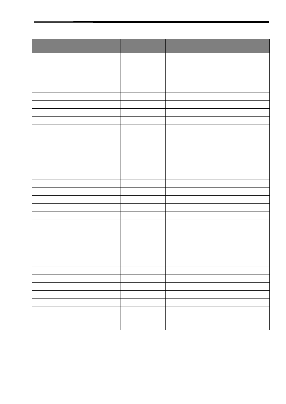
Tally Dascom 2610
MTPL
IBM
XL24
IBM
AGM
Epson
LQ-2550
Epson
LQ-2170
Code
Function
√
* * * *
<ESC>[4m
Underline ON
√
* * * *
<ESC>[4 SP L
Set vertical spacing to 8 lpi
√
* * * *
<ESC>[4w
Set 10 cpi
√
* * * *
<ESC>[4y
Selecting NLQ printing quality at 10 cpi
√
* * * *
<ESC>[4z
Line density 8 lpi (= line spacing 1/8 inch)
√
* * * *
<ESC>[5{
Select fanfold paper mode tractor 1
√
* * * *
<ESC>[6{
Select fanfold paper mode tractor 2
√
* * * *
<ESC>[50m
Proportional font OFF
√
* * * *
<ESC>[50{
Page at print position
√
* * * *
<ESC>[51{
Page at tear off position (perforation)
√
* * * *
<ESC>[52{
Page at view position
√
* * * *
<ESC>[53m
Overlining ON
√
* * * *
<ESC>[55m
Overlining OFF
√
* * * *
<ESC>[5n
Request status report
√
* * * *
<ESC>[5w
Set 12 cpi
√
* * * *
<ESC>[5y
NLQ with 12 cpi
√
* * * *
<ESC>[5z
Graphics normal
√
* * * *
<ESC>[6~
Initialize the printer
√
* * * *
<ESC>[6 SP K
Set horizontal pitch to 6 cpi
√
* * * *
<ESC>[6w
Set 15 cpi
√
* * * *
<ESC>[6z
Graphics inverted
√
* * * *
<ESC>[7w
Set 17.1 cpi
√
* * * *
<ESC>[7y
Proportional font OFF
√
* * * *
<ESC>[7z
Bit 8 = unchanged
√
* * * *
<ESC>[8w
Reset double stroke
√
* * * *
<ESC>[8y
Right justification ON
√
* * * *
<ESC>[8z
Set bit 8 = 0
√
* * * *
<ESC>[9 SP L
Set vertical spacing to 2 lpi
√
* * * *
<ESC>[9w
Set double stroke
√
* * * *
<ESC>[9y
Centering ON
√
* * * *
<ESC>[9z
Set bit 8 = 1
√
<ESC>[g<n1> <n2><0>
Set graphics print to 60 dpi
√
<ESC>[g<n1> <n2><1>
Set graphics print to 120 dpi
√
<ESC>[g<n1> <n2><11>
Set graphics print to 180 dpi
√
<ESC>[g<n1> <n2><12>
Set graphics print to 360 dpi
87
 Loading...