

Page 1
Data sheet
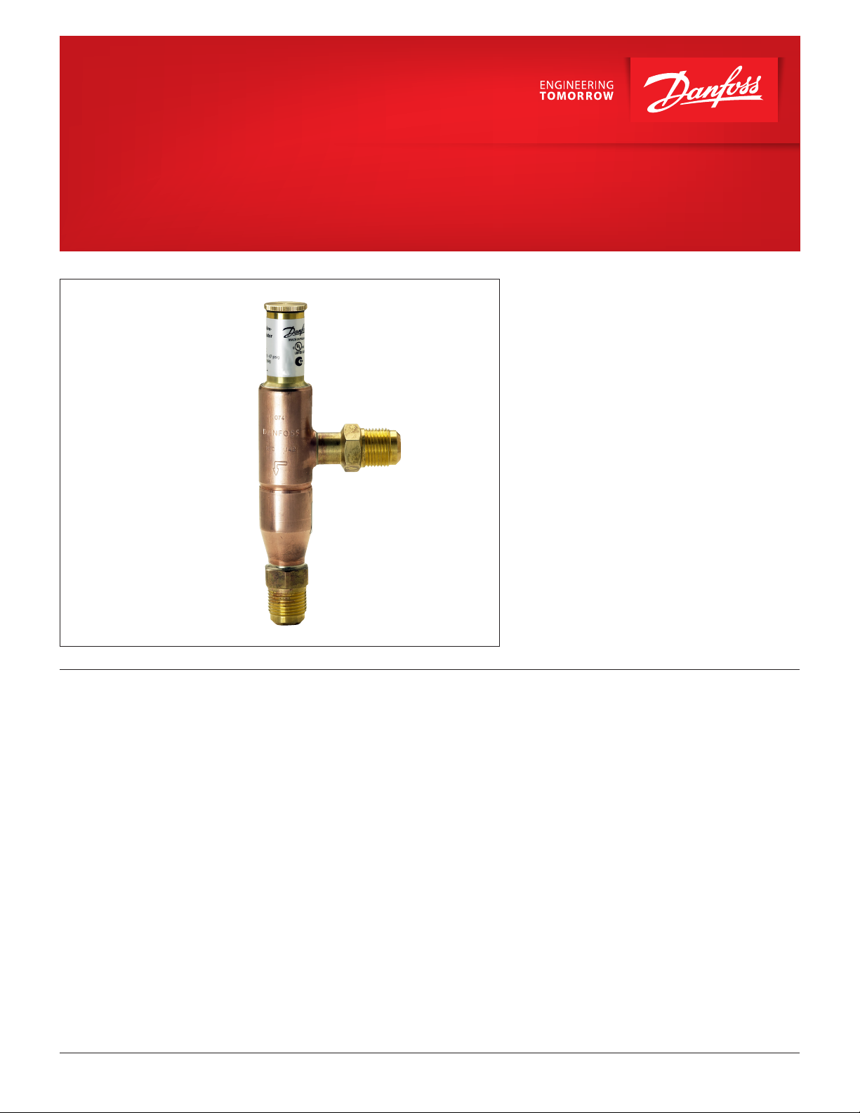
Hot gas bypass regulator
Type KVC
KVC hot gas bypass regulator are used to adapt
compressor capacity to actual evaporator load by
supplying a replacement capacity in form of
hot / cool gas.
It is installed in a bypass line between the high and
low pressure sides of the refrigeration system and
is designed for direct gas injection into the suction
line.
Features • Accurate, adjustable pressure regulation
• Wide capacity and operating range
• Pulsation damping design
• Stainless steel bellows
© Danfoss | DCS (rm) | 2020.10
• Compact angle design for easy installation
• ”Hermetic” brazed construction
• Available with are or ODF solder connections
• May be used in the following EX range: Category
3 (Zone 2)
DKRCC.PD.HE0.A7.22 | 1
Page 2
Data sheet | Hot gas bypass regulator, type KVC
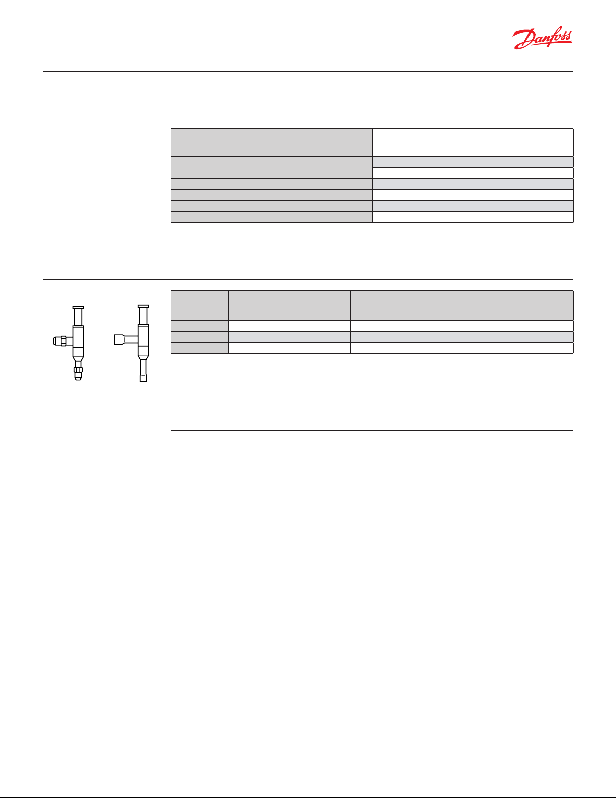
Approvals
Technical data
Metric conversions:
1 psi = 0.07 bar
5
⁄9 (t
°F - 32) = t
1
1 TR = 3.5 kW
°C
2
Ordering
UL LISTED, le SA7200
EAC
Refrigerants
Regulating range
Maximum working pressure MWP = 406 psig
Maximum test pressure Pe = 450 psig
Medium temperature range -49 – 266 °F
Maximum P-band 29 psi
This product is approved for R290, R454A, R454C,
R455A, R600, R600a, R1234ze(E), R1234yf, R1270
by ignition source assessment in accordance with
standard EN ISO80079-36. Flare connections are
R22, R134a, R290, R404A, R407A, R407C, R407F, R407H, R448A,
R449A, R449B, R450A, R452A, R454A, R454C, R455A, R507A, R513A,
R515B, R516A, R600, R600a, R1234ze(E), R1234yf, R1270
Pe = 3.00 – 87.00 psig
Factory setting = 29 psig
For complete list of approved refrigerants, visit
www.products.danfoss.com and search for
individual code numbers, where refrigerants are
listed as part of technical data.
only approved for A1 and A2L refrigerants.
Rated capacity 1)
= 77 °F
l
[TR]
Type
KVC 12 2.14 1.36 2.02 2.31
KVC 15 4.17 2.65 3.93 4.50
KVC 22 5.35 3.41 5.04 5.78 – –
1
) Rated capacity is based on:
Suction gas temperature ts = 14 °F
Condensing temperature t
Oset ∆p = 10 psi
2
) KVC are delivered without are nuts. Separate are nuts can be supplied:
1⁄2 in code no 011L1103
5⁄8 in code no 011L1167
R22 R134a R404A/R507 R407C [in] [in]
Flare
connection 2)
1
⁄2 034L0141
5
⁄8 034L0142
Code no.
Solder
connection
1
⁄2 034L0143
5
⁄8 034L0147
7
⁄8 034L0144
Code no.
Note:
The connection dimensions chosen must not be
too small, as gas velocities in excess of 130 ft / s at
the inlet of the regulator can result in ow noise.
If the temperature in the discharge gas line is too
high according to the compressor specications, it
is recommanded to install a liquid injection valve in
a bypass from the liquid line to the suction line.
© Danfoss | DCS (rm) | 2020.10
DKRCC.PD.HE0.A7.22 | 2
Page 3
Data sheet | Hot gas bypass regulator, type KVC
Replacement capacity
Metric conversions:
1 psi = 0.07 bar
5
⁄9 (t
°F - 32) = t
1
1 TR = 3.5 kW
1 in = 25.4 mm
°C
2
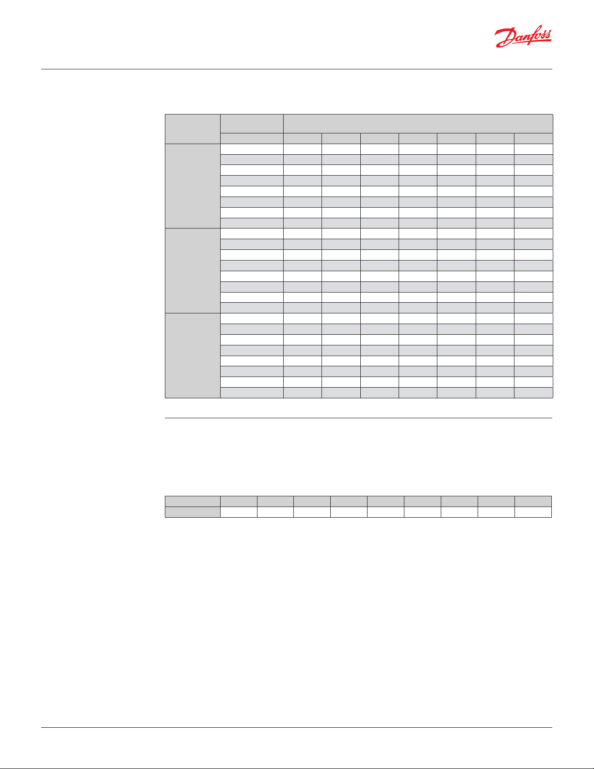
Maximum regulator capacity Qe 1)
Type
KVC 12
KVC 15
KVC 22
1
) The capacities are based on: Condensing temperature tl = 77 °F
Oset ∆p
[psi] -50 -40 -25 -10 10 30 50
1.5 – 0.68 0.70 0.71 0.73 0.75 0.77
2.0 – 0.93 0.95 0.97 1.00 1.03 1.05
3.0 – 1.33 1.36 1.39 1.43 1.47 1.51
5.0 – 1.75 1.79 1.83 1.88 1.93 1.98
7.5 – 1.93 1.97 2.01 2.07 2.12 2.18
10.0 – 2.00 2.04 2.08 2.14 2.20 2.26
15.0 – 2.19 2.24 2.28 2.35 2.41 2.48
20.0 – 2.62 2.67 2.72 2.80 2.87 2.94
1.5 – 1.01 1.03 1.06 1.09 1.12 1.15
2.0 – 1.20 1.23 1.25 1.29 1.32 1.35
3.0 – 1.73 1.77 1.80 1.85 1.90 1.95
5.0 – 2.64 2.69 2.75 2.83 2.90 2.98
7.5 – 3.39 3.46 3.54 3.63 3.73 3.83
10.0 – 3.90 3.98 4.06 4.17 4.28 4.39
15.0 – 4.76 4.66 4.75 4.88 5.01 5.14
20.0 – 5.05 5.16 5.27 5.42 5.57 5.72
1.5 – 1.09 1.12 1.14 1.17 1.21 1.24
2.0 – 1.38 1.41 1.44 1.48 1.52 1.56
3.0 – 1.89 1.93 1.97 2.02 2.07 2.12
5.0 – 2.88 2.94 3.00 3.08 3.16 3.24
7.5 – 4.02 4.11 4.19 4.31 4.43 4.54
10.0 – 4.98 5.09 5.20 5.35 5.50 5.64
15.0 – 6.35 6.49 6.63 6.82 7.01 7.20
20.0 – 7.10 7.25 7.40 7.60 7.79 7.99
Regulator capacity Q
1
) [TR] suction gas temperature ts after
e
pressure / temperature reduction [°F]
R22
Correction factors for condensing temperature tl.
When liquid temperature tl is other than 77 °F,
adjust the table capacities by multiplying them
by the appropriate correction factor found in the
following table.
Correction factors for condensing temperature t
tl [°F] 50 59 68 77 86 95 104 113 122
R22 0.9 0.93 0.96 1.00 1.05 1.1 1.13 1.18 1.24
System capacity × correction factor = table capacity
l
© Danfoss | DCS (rm) | 2020.10
DKRCC.PD.HE0.A7.22 | 3
Page 4

Data sheet | Hot gas bypass regulator, type KVC
Replacement capacity
(continued)
Metric conversions:
1 psi = 0.07 bar
5
⁄9 (t
°F - 32) = t
1
1 TR = 3.5 kW
1 in = 25.4 mm
°C
2
Maximum regulator capacity Qe 1)
Type
KVC 12
KVC 15
KVC 22
1
) The capacities are based on: Condensing temperature tl = 77 °F
Oset ∆p
[psi] -50 -40 -25 -10 10 30 50
1.5 – – 0.41 0.43 0.46 0.48 0.50
2.0 – – 0.58 0.60 0.62 0.66 0.70
3.0 – – 0.83 0.86 0.91 0.95 1.00
5.0 – – 1.09 1.14 1.20 1.25 1.31
7.5 – – 1.20 1.25 1.31 1.37 1.44
10.0 – – 1.25 1.30 1.36 1.42 1.49
15.0 – – 1.36 1.42 1.49 1.56 1.63
20.0 – – 1.62 1.69 1.78 1.86 1.94
1.5 – – 0.62 0.65 0.68 0.72 0.76
2.0 – – 0.74 0.78 0.82 0.86 0.90
3.0 – – 1.08 1.13 1.18 1.24 1.28
5.0 – – 1.64 1.72 1.79 1.87 1.96
7.5 – – 2.12 2.21 2.30 2.41 2.51
10.0 – – 2.45 2.54 2.65 2.77 2.88
15.0 – – 2.87 2.96 3.11 3.25 3.40
20.0 – – 3.13 3.26 3.44 3.61 3.79
1.5 – – 0.67 0.70 0.73 0.78 0.82
2.0 – – 0.86 0.90 0.94 0.97 1.02
3.0 – – 1.18 1.22 1.28 1.33 1.39
5.0 – – 1.80 1.86 1.96 2.04 2.12
7.5 – – 2.52 2.62 2.74 2.87 2.99
10.0 – – 3.13 3.25 3.41 3.55 3.71
15.0 – – 4.00 4.15 4.34 4.54 4.74
20.0 – – 4.43 4.61 4.82 5.05 5.28
Regulator capacity Q
1
) [TR] suction gas temperature ts after
e
pressure / temperature reduction [°F]
R134 a
Correction factors for condensing temperature tl.
When liquid temperature tl is other than 77 °F,
adjust the table capacities by multiplying them
by the appropriate correction factor found in the
following table.
Correction factors for condensing temperature t
tl [°F] 50 59 68 77 86 95 104 113 122
R134a 0.88 0.92 0.96 1.00 1.05 1.1 1.16 1.23 1.31
System capacity × correction factor = table capacity
l
© Danfoss | DCS (rm) | 2020.10
DKRCC.PD.HE0.A7.22 | 4
Page 5

Data sheet | Hot gas bypass regulator, type KVC
Replacement capacity
(continued)
Metric conversions:
1 psi = 0.07 bar
5
⁄9 (t
°F - 32) = t
1
1 TR = 3.5 kW
1 in = 25.4 mm
°C
2
Maximum regulator capacity Qe 1)
Type
KVC 12
KVC 15
KVC 22
1
) The capacities are based on: Condensing temperature tl = 77 °F
Oset ∆p
[psi] -50 -40 -25 -10 10 30 50
1.5 0.57 0.58 0.62 0.64 0.67 0.70 0.74
2.0 0.79 0.81 0.85 0.88 0.92 0.97 1.01
3.0 1.16 1.19 1.23 1.28 1.34 1.40 1.46
5.0 1.54 1.58 1.64 1.69 1.77 1.85 1.93
7.5 1.68 1.73 1.79 1.86 1.96 2.05 2.13
10.0 1.74 1.78 1.85 1.93 2.02 2.11 2.21
15.0 1.89 1.94 2.01 2.10 2.20 2.31 2.41
20.0 2.27 2.33 2.42 2.51 2.62 2.74 2.85
1.5 0.86 0.89 0.92 0.96 1.01 1.06 1.10
2.0 1.05 1.07 1.11 1.16 1.21 1.27 1.32
3.0 1.51 1.55 1.61 1.66 1.74 1.82 1.90
5.0 2.29 2.34 2.44 2.53 2.65 2.77 2.89
7.5 2.94 3.01 3.14 3.26 3.42 3.58 3.74
10.0 3.38 3.47 3.61 3.75 3.93 4.11 4.30
15.0 3.95 4.06 4.22 4.39 4.61 4.82 5.04
20.0 4.36 4.48 4.66 4.85 5.09 5.34 5.58
1.5 0.92 0.96 0.99 1.02 1.08 1.12 1.18
2.0 1.19 1.22 1.27 1.31 1.38 1.44 1.51
3.0 1.71 1.75 1.83 1.89 1.98 2.08 2.17
5.0 2.63 2.71 2.81 2.92 3.06 3.20 3.34
7.5 3.58 3.67 3.82 3.96 4.17 4.35 4.54
10.0 4.33 4.46 4.63 4.81 5.04 5.28 5.51
15.0 5.49 5.64 5.86 6.08 6.39 6.69 6.99
20.0 6.31 6.49 6.74 7.01 7.35 7.70 8.04
Regulator capacity Q
1
) [TR] suction gas temperature ts after
e
pressure / temperature reduction [°F]
R404A/R507
Correction factors for condensing temperature tl.
When liquid temperature tl is other than 77 °F,
adjust the table capacities by multiplying them
by the appropriate correction factor found in the
following table.
Correction factors for condensing temperature t
tl [°F] 50 59 68 77 86 95 104 113 122
R404A/R507 0.84 0.89 0.94 1.00 1.07 1.06 1.26 1.4 1.57
System capacity × correction factor = table capacity
l
© Danfoss | DCS (rm) | 2020.10
DKRCC.PD.HE0.A7.22 | 5
Page 6

Data sheet | Hot gas bypass regulator, type KVC
Replacement capacity
(continued)
Metric conversions:
1 psi = 0.07 bar
5
⁄9 (t
°F - 32) = t
1
1 TR = 3.5 kW
1 in = 25.4 mm
°C
2
Maximum regulator capacity Qe 1)
Type
KVC 12
KVC 15
KVC 22
1
) The capacities are based on: Condensing temperature tl = 77 °F
Oset ∆p
[psi] -50 -40 -25 -10 10 30 50
1.5 – 0.73 0.76 0.77 0.79 0.81 0.83
2.0 – 1.00 1.03 1.05 1.08 1.11 1.13
3.0 – 1.44 1.47 1.50 1.54 1.59 1.63
5.0 – 1.89 1.93 1.98 2.03 2.08 2.14
7.5 – 2.08 2.13 2.17 2.24 2.29 2.35
10.0 – 2.16 2.20 2.25 2.31 2.38 2.44
15.0 – 2.37 2.42 2.46 2.54 2.60 2.68
20.0 – 2.83 2.88 2.94 3.02 3.10 3.18
1.5 – 1.09 1.11 1.14 1.18 1.21 1.24
2.0 – 1.30 1.33 1.35 1.39 1.43 1.46
3.0 – 1.87 1.91 1.94 2.00 2.05 2.11
5.0 – 2.85 2.91 2.97 3.06 3.13 3.22
7.5 – 3.66 3.74 3.82 3.92 4.03 4.14
10.0 – 4.21 4.30 4.38 4.50 4.62 4.74
15.0 – 4.92 5.03 5.13 5.27 5.41 5.55
20.0 – 5.45 5.57 5.69 5.85 6.02 6.18
1.5 – 1.18 1.21 1.23 1.26 1.31 1.34
2.0 – 1.49 1.52 1.56 1.60 1.64 1.68
3.0 – 2.04 2.08 2.13 2.18 2.24 2.29
5.0 – 3.11 3.18 3.24 3.33 3.41 3.50
7.5 – 4.34 4.44 4.53 4.65 4.78 4.90
10.0 – 5.38 5.50 5.62 5.78 5.94 6.09
15.0 – 6.86 7.01 7.16 7.37 7.57 7.78
20.0 – 7.67 7.83 7.99 8.21 8.41 8.63
Regulator capacity Q
1
) [TR] suction gas temperature ts after
e
pressure / temperature reduction [°F]
R407C
Correction factors for condensing temperature tl.
When liquid temperature tl is other than 77 °F,
adjust the table capacities by multiplying them
by the appropriate correction factor found in the
following table.
Correction factors for condensing temperature t
tl [°F] 50 59 68 77 86 95 104 113 122
R407C 0.88 0.91 0.95 1.00 1.05 1.11 1.18 1.26 1.35
System capacity × correction factor = table capacity
l
© Danfoss | DCS (rm) | 2020.10
DKRCC.PD.HE0.A7.22 | 6
Page 7

Data sheet | Hot gas bypass regulator, type KVC
Sizing
Metric conversions:
1 psi = 0.07 bar
5
⁄9 (t
°F - 32) = t
1
1 TR = 3.5 kW
1 in = 25.4 mm
°C
2
Valve selection
Example
For optimum performance, it is important to select
a KVC valve according to system conditions and
application.
The following data must be used when sizing a KVC
valve:
Note:
When selecting the appropriate valve, it may be
necessary to convert the actual capacity using a
correction factor for condensing temperature.
This is due to dierences between the table rated
conditions and the design conditions.
The following example illustrates how this is done.
Step 1:
Determine the correction factor for the
condensing temperature tl.
• Refrigerant: HCFC, HFC and HC
• Suction temperature at maximum
compressor / evaporator load ts in [°F] / [psig]
• Minimum suction temperature ts in [°F] / [psig]
• Compressor capacity in [TR]
• Evaporating load in [TR]
• Condensing temperature tl in [°F]
• Connection type: are or solder
• Connection size [in]
Conditions:
• Refrigerant type: R134a
• Suction temperature at maximum
compressor / evaporator load ts: 0 °F ~ 7 psi.
• Minimum suction temperature ts: 10 °F ~ 12 psi.
• Compressor capacity at 10 °F: 4.4 TR
• Evaporating load at 10 °F: 2.85 TR
• Condensing temperature tl: 95 °F
• Connection type: solder
• Connection size: 5⁄8 in
From the correction factors table (see below)
a condensing temperature of 95 °F, R134a
corresponds to a factor of 1.1.
Correction factors for condensing temperature t
tl [°F] 50 59 68 77 86 95 104 113 122
R 134a 0.88 0.92 0.96 1.00 1.05 1.1 1.16 1.23 1.31
R22 0.9 0.93 0.96 1.00 1.05 1.1 1.13 1.18 1.24
R404A/R507 0.84 0.89 0.94 1.00 1.07 1.16 1.26 1.4 1.57
R407C 0.88 0.91 0.95 1.00 1.05 1.11 1.18 1.26 1.35
l
Step 2:
The required replacement capacity is dened as
the (compressor capacity – the evaporator load)
divided by the correction factor is equal:
(4.4-2.85) / 1.1 = 1,41 TR
Step 3:
Now select the appropriate capacity table
and choose the column for minimum suction
temperature ts = 10 °F.
KVC 15 delivers 1.79 TR at an oset of 5 psi.
Based on the required connection size of
5
⁄8 in ODF, the KVC 15 is the proper selection for this
example.
Using the corrected replacement capacity, select
a valve that provides an equivalent or greater
capacity than required.
From the correction factors table (see below) a
condensing temperature of
95 °F, R134a corresponds to a factor of 1.1.
Step 4:
KVC 15, 5⁄8 in ODF
Code no 034L0147.
© Danfoss | DCS (rm) | 2020.10
DKRCC.PD.HE0.A7.22 | 7
Page 8

Data sheet | Hot gas bypass regulator, type KVC
Design / Function KVC
Hot gas bypass regulator type KVC opens on a fall in
pressure on the outlet side, i.e. when the pressure in
the evaporator reaches the set value.
Type KVC regulates on outlet pressure (suction
pressure) only. Pressure variations on the inlet side
of the regulator do not aect the degree of opening
as the valve is equipped with equalization bellows (6).
The bellows has an eective area corresponding to
that of the valve seat neutralizing any aect to the
setting.
1. Protective cap
2. Gasket
3. Setting screw
4. Main spring
5. Valve body
6. Equalization bellows
7. Valve plate
8. Valve seat
9. Damping device
P-band and Oset
Capacity
The regulator is also equipped with a damping
device (9) providing protection against pulsations
which can normally arise in a refrigeration system.
The damping device helps to ensure long life
for the regulator without impairing regulation
accuracy.
Danfoss
34L182.11
© Danfoss | DCS (rm) | 2020.10
Oset
P-band
Proportional band:
The proportional band or P-band is dened as the
amount of pressure required to move the valve
plate from closed to full open position.
If the setting is 80 psig and the p-band is 29 psi,
the pressure at which the valve gives maximum
capacity will be 51 psig.
Setting
[bar]
Oset:
The oset is dened as the permissible pressure
variation in suction line pressure (temperature).
It is calculated as the dierence between the
required working pressure and the minimum
allowable pressure.
The oset is always a part of the P-band.
Example with R 404A:
A suction temperature ahead of the compressor
of 25 °F ~ 61 psig is required, and the temperature
must not drop below 14 °F ~ 48 psig.
The oset will then be 13 psi.
DKRCC.PD.HE0.A7.22 | 8
Page 9

Danf
already on order pro
All trademarks in this material are property of the respec
Dimensions and weights KVC
Type
Connection
Flare
Solder
ODF
NV
NV
1
H
2
H
1
B
2
1
C
solder
øD
[in] [in] [in] [in] [in] [in] [in] [in] [in] [lbs]
KVC 12
Metric conversions
1 in = 25.4 mm
1 lb = 0.454 kg
oss can accept no responsibility for possible errors in catalogues, brochures and other printed material. Danfoss reserves the right to alter its products without notice. This also applies to products
vided that such alterations can be made without subsequential changes being necessary eady agreed.
KVC 15
KVC 22 –
tive companies. Danfoss and the Danfoss logotype are trademarks of Danfoss A/S. All rights reserved.
1
⁄2
5
⁄8
1
⁄2
5
⁄8
7
8
/
3
⁄4
15
⁄16
15
⁄16 7.047 3.898 2.520 0.394 1.181 0.88
15
⁄16 7.047 3.898 2.520 0.472 1.181 0.88
– – 7.047 3.898 2.520 0.669 1.181 0.88
Net
weight
© Danfoss | DCS (rm) | 2020.10
DKRCC.PD.HE0.A7.22 | 9
 Loading...