

Page 1
Data sheet
Actuators for modulating or 3-point control
AMV(E) 413, AMV(E) 613, 633 - with safety function
AMV(E) 410, AMV(E) 610 - without safety function
Description / Application
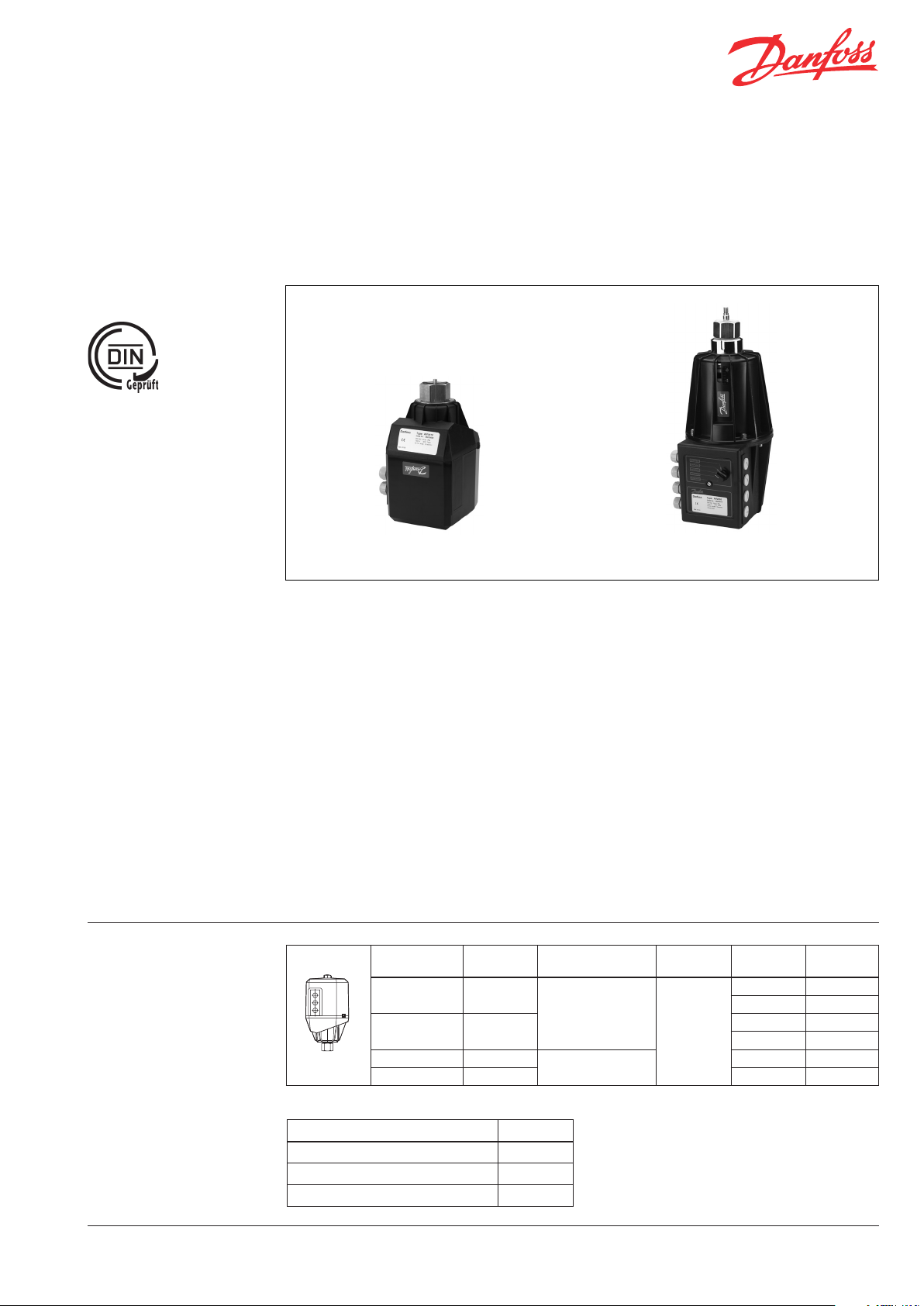
AMV 410, 413 AMV(-H) 610, 613, 633
AME 410, 413 AME(-H) 610, 613, 633
Ordering
AMV(E) 410, 413 is an electrical actuator with
synchronous motor and gear.
AMV(E) 610, 613, 633 is an electrohydraulic
actuator with a hydraulic pump and magnetic
valves.
The actuators can be used in connection with
the following valves:
- two way: VFG 2 (21), VFG 25, VFU 2 (NC),
VFGS 2 (Steam), DN 15 - 250
- combination valve: AFQM (flow controller
with integrated valve), DN 40 - 125
The Danfoss controller ECL or other controllers
can be applied, using either three point step
signal or modulated signal. The actuators are
applied mainly in heating and district heating
systems for water and steam up to 350 °C.
Type
AMV 410 -
AMV 413 x
AME 410 -
AME 413 x 2 082G0613
Safety
function
Supply voltage
step signal/ 230 V~
0(2) - 10 V dc/ 24V~
The actuators fullfil following demands:
- Design-tested acc. to DIN EN 60 730
- DIN EN 50081-2 and DIN EN 50082-2
- Type-tested acc. to DIN 32730 (safety
function): Types: AMV(E) 413, 613, 633
Main data:
Nominal voltage:
- 230 V / 50 Hz and 24 V / 50 Hz
Input signal:
- Three-point control signal
- Modulate control signal
Manual adjustment:
- Electrical
- Mechanical
Additional equipment:
- End switch
- Potentiometer
Control input/
Three point
0(4) - 20 mA dc
Pos. time
(s/mm)
15
0(4) - 20 mA / 0(2) - 10 V
End
switch
- 082G0608
1 082G0609
- 082G0611
1 082G0612
2 082G0610
Code No.
Accessories for AMV 410/413
Type Code No.
Auxiliary Switch 082G0695
Potentiometer 5 kOhm 082G0696
Potentiometer 1 kOhm 082G1535
DEN-SMT/SI VD.AA .O3.02 © Danfoss 04/2011 1
Page 2
Data sheet AMV: 3-point control AME: Modulating control
Ordering (continuous)
Technical data
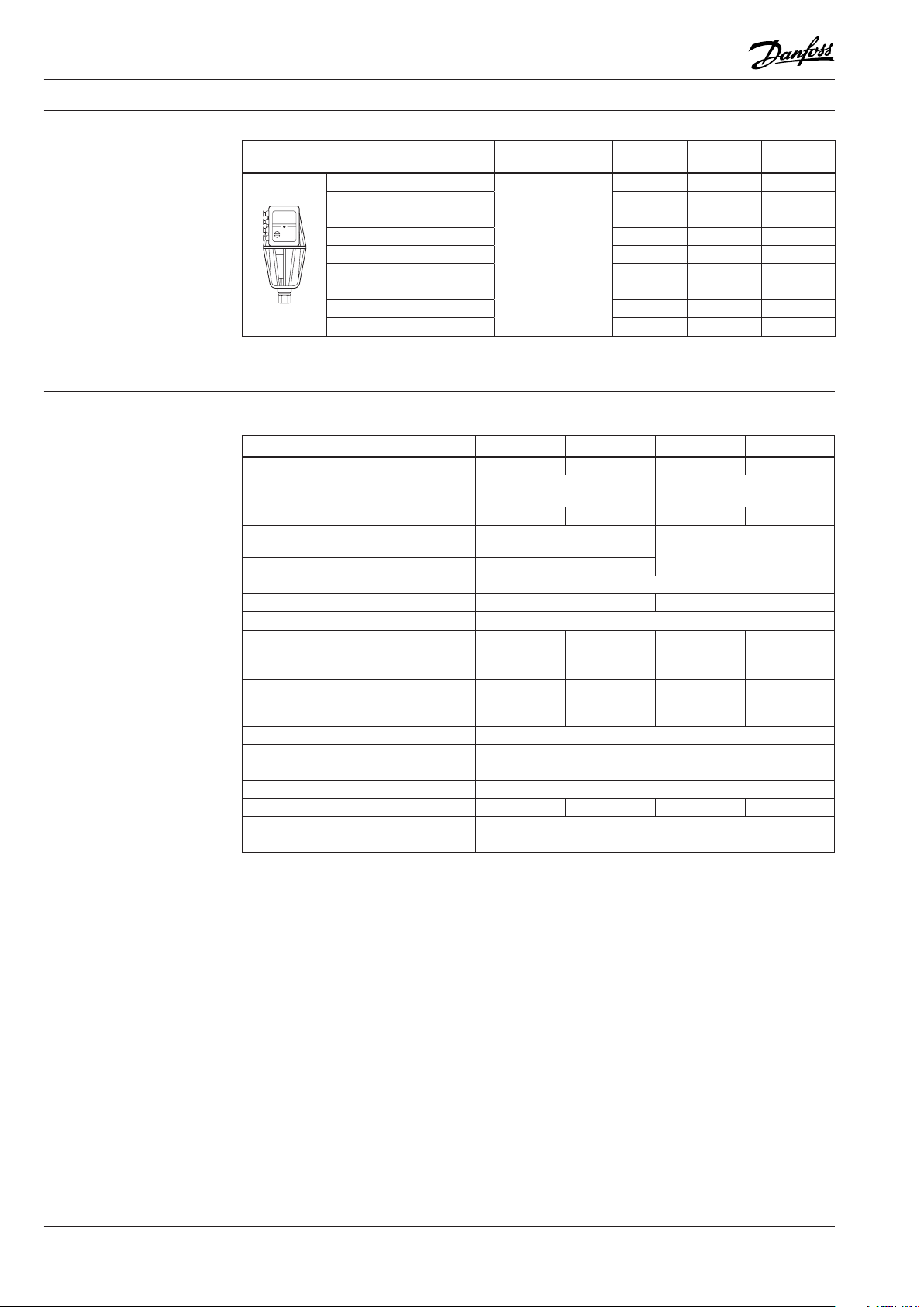
Type
AMV 610 -
Safety
function
Control input/
Supply voltage
Pos. time
(s/mm)
End
switch
Code No.
15 2 082G0614
AMV 613 x 15 2 082G0616
AMV 613-Y60
AMV 633 x 4 2 082G0618
AMV-H 613
1)
x 15 2 082G0617
Three point
step signal/ 230 V~
2)
x 15 2 082G0621
AME 610 - 15 2 082G0615
AME 613 x
AME 633 x 4 2 082G0620
1)
AME-H 613
Valve stroke Y60 for higher kvs D N 150 - 250
2)
Version with mechanical adjustment and safety function, not type tested acc. DIN 32 730
2)
x 15 2 082G0622
0(4) - 20 mA dc
0(2) - 10 V dc/ 230V~
15 2 082G0619
Actuators AMV / AME 410, 413
Actuator type AMV 413 AMV 410 AME 413 AME 410
Safety function
Power supply/frequency
Power consumption VA 10 4 12 6
Input signal
Output signal positioning stroke -
Stroke mm 20
End switches (2 pieces) 230 V, 1A 24 V, 1A
Positioning time s/mm 15
Approx. positioning time with
safety return function
Positioning force N 800 1000 800 1000
Power failure response
Protection code EN 60 529 IP 54
Max. ambient temperature
Max. storage temperature -40 to +70
Manual positioning Electrical
Weight kg 2.8 2.1 2.8 2.1
Body material Polyamide, glass fiber reinforced
Union nut / connection and materials Brass / steel
1)
Effective direction: stem to drive out, i.e. valve to close.
2)
Effective direction can be adapted to requirements.
3)
If the valve is mounted with the actuator hanging IP 52
1)
s/mm
stroke
°C
x - x -
230 V, +10 to - 15 %
50/60 Hz
Three-point step signal
230 V / 50 Hz
24 V, +10 to - 15 %
50/60 Hz
0(4) - 20 mA dc
0(2) - 10 V dc
0.5 to 1 - 0.5 to 1 -
Safety return
function, stem
to drive out
Stem remains
in last position
Safety return
function, stem
to drive out
3)
-10 to +50
2)
Stem remains
in last position
2 VD.AA .O3.02 © Danfoss 04/2011 DEN-SMT/SI
Page 3
Data sheet AMV: 3-point control AME: Modulating control
Technical data (continuous)
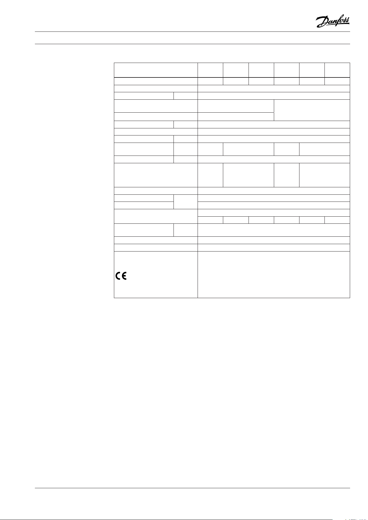
Actuators AMV(-H) / AME(-H) 610, 613, 633
Actuator type AMV 610 AMV 613
Safety function
1)
- x x - x x
Power supply/frequency 230 V, +10 to - 15 %, 50/60 Hz
Power consumption VA 15
Input signal
Three-point step signal
230 V / 50 Hz
Output signal positioning stroke 0(4) - 20 mA dc
Stroke mm 30
End switches (2 pieces) Change-over switch, alternating voltage max. 250 V, 1A
Positioning time s/mm 15 (4 - version AMV / AME 633)
Approx. positioning time
with safety return function
s/mm
stroke
- 0.5 to 1 - 0.5 to 1
Positioning force N 1200
Stem
Power failure response
remains
in last
position
stem to drive out
Protection code EN 60 529 IP 54
Max. ambient temperature
Max. storage temperature -40 to +70
Manual positioning
Weight
°C
- - mechanic. - - mechanic.
kg 4
Body material Polyamide, glass fiber reinforced, ABS
Union nut / connection and materials Brass / steel
In accordance with following directives:
Low Voltage Directive 73/23/EEC and 93/68/EEC, EN 60730/2/14
EMC - Directive 89/336/EEC, 92/31/EEC, 93/68/EEC, EN 50081-1
- Confirmation
DIN 32730
DIN EN 50081-2
DIN EN 50082-2
DIN EN 60730
DIN EN 61010-1
1) Effective direc tion: stem to drive out, i.e. val ve to close.
2) Effective direc tion can be adapted to requir ements.
AMV-H 613
AMV 633
Safety return
function,
AME 610 AME 613
Stem
remains
in last
position
-10 to +50
Electrical
0(4) - 20 mA dc
0(2) - 10 V dc
Safety return
function,
stem to drive out
AME-H
AME 633
2)
DEN-SMT/SI VD.AA .O3.02 © Danfoss 04/2011 3
Page 4

Data sheet AMV: 3-point control AME: Modulating control
Installation position
Type Hotwater Steam
AMV / AME
410, 413
AMV / AME
610, 613, 630, 633
Independent of
temperature and
nominal diameter
nominal diameter up to DN 80
up to 120 °C,
Dimensions
125
AMV / AME 410 AMV / AME 413 AMV / AME 610, 613, 633
4 VD.AA .O3.02 © Danfoss 04/2011 DEN-SMT/SI
Page 5

Data sheet AMV: 3-point control AME: Modulating control
Design
AMV / AME 410, 413
1 Display of direction of motion
2 Electrical manual adjustment
by push-button
3 Stroke indicator
AMV / AME 610, 613, 633
1 Electrical manual adjustment
by rotary switch
2 Stroke indicator
3 Union nut
Manual adjusting
1
2
3
AMV / AME 410, 413 AMV / AME 610, 613, 633
1
2
3
Electrical operation
AMV / AME
410, 413
Electrical operation
AMV(-H) / AME(-H)
610, 613, 633
Mechanical operation
AMV(-H) / AME(-H)
610, 613
DEN-SMT/SI VD.AA .O3.02 © Danfoss 04/2011 5
Page 6

Data sheet AMV: 3-point control AME: Modulating control
Power supply
230 V AC
with connection of STB/SDW
remove jumper
to from
controller
open
close
open
stroke
close
open
close
Wiring / Connection diagramm
AMV 410 AMV 413
with connection of STB/SDW
remove jumper
Power supply
230 V AC
AME 410, 413
open
close
open
stroke
close
open
close
to from
controller
GND.
0(2) - 10V oder
0(4) - 20m A
+ U – I
AUSG . EING.
STB
STW
SD B
ZU AUF
GRENZK. GRENZK.
PE 24V AC
0(4) - 20 mA DC
0(2) - 10 V DC
0(4) - 20 mA DC
0(2) - 10 V DC
At connection of STB, STW, SDB
remove jumper
24 V AC
PE
Valve
“CLOSE”
extend stem
Valve
“OPEN”
stem raised
Input
Output stroke
Power supply
Limit contacts
maks. 24 V
6 VD.AA .O3.02 © Danfoss 04/2011 DEN-SMT/SI
Page 7

Data sheet AMV: 3-point control AME: Modulating control
– mA 20
1
19
16
18
15
17
14
9
13
11
8
10
7
12
5
4
6
3
2
L
+ mA
Open
Close
PE
L
L
L
PE
N
Manual switch
Open
Close
Valve stroke
0/4 - 20 mA
External control
pot. freie Kontakte
Limit contacts for position “CLOSE”
Limit contacts for position “OPEN”
Safety pressure limiter
Safety temperature limiter
Power supply
L/N/PE ~ 230 V/ 50 Hz
Open
Stop
Aut o
Stop
Close
Br .
Br .
Wiring / Connection
diagramm (continuous)
AMV 610, 613, 633
DEN-SMT/SI VD.AA .O3.02 © Danfoss 04/2011 7
AME 610, 613, 633
Output stroke
0(4) - 20 nA
0(2) - 10 V
GND Input
0(4) - 20 nA
0(2) - 10 V
OPEN
End switches
CLOSE
at connection of STB, STW, SDB
remove jumper
N
L
Power supply
230 V AC
PE
Page 8

Data sheet AMV: 3-point control AME: Modulating control
Actuator - valve
combinations
AMV / AME 410, 413
Valve type
DN 15 - 80 15 - 65 15 - 80 40, 50 65, 80
Medium Hot water Steam Hot water
Max.
temp.
(°C)
PN 16, 25, 40 25
Remark
VFG 2
VFG 21
VFG 25
200 (VFG 2)
150 (VFG 21)
200 (VFG 25)
VFU 2 VFGS 2 AFQM 6 AFQM
200 350 150 150
NC valve,
actuator with
safety function
with extension
piece ZF4,
ZF5
Flow control with integrated
control valve
AMV(-H) / AME(-H) 610, 613, 633
Valve type
DN 15 - 250 15 - 125 15 - 250 65 - 125
Medium Hot water Steam Hot water
Max.temp.
(°C)
PN 16, 25, 40 25
Remark
VFG 2
VFG 21
VFG 25
200 200 350 150
VFU 2 VFGS 2 AFQM
NC valve,
actuator with
safety function
with extension
piece ZF4, ZF5
Flow control with integrated
control valve
8 VD.AA .O3.02 Produce d by Danfoss A/S © 04/ 2011
 Loading...